Embed Size (px)
Citation preview
Chapter
7Managing a Cisco Internetwork
ThE FOLLOWING ICND1 ExAM TOPICS ARE COVERED IN ThIS ChAPTER:
u1 LAN Switching Technologies
u■ Verify network status and switch operation using basic
utilities such as ping, telnet, and ssh
u1 IP Routing Technologies
u■ Configure and verify utilizing the CLI to set basic Router
configuration
u■ Cisco IOS commands to perform basic router setup
u■ Verify router configuration and network connectivity
u■ Cisco IOS commands to review basic router information
and network connectivity
u1 IP Services
u■ Configure and verify DHCP (IOS Router)
u■ configuring router interfaces to use DHCP
u■ DHCP options
u■ excluded addresses
u■ lease time
u■ Configure and verify NTP as a client
Here in Chapter 7, I’m going to show you how to manage Cisco routers and switches on an internetwork. You’ll find out how to manage Cisco devices by using the copy command with a TFTP
host and how to configure DHCP and NTP, plus you’ll get a survey of the Cisco Discovery Protocol (CDP). I’ll also show you how to resolve hostnames.
I’ll wrap up the chapter by guiding you through some important Cisco IOS troubleshooting techniques to ensure that you’re well equipped with these key skills.
To find up-to-the minute updates for this chapter, please see www.lammle.com/forum or the book’s web page at www.sybex.com.
The Internal Components of a Cisco Router and SwitchUnless you happen to be really savvy about the inner and outer workings of all your car’s systems and its machinery and how all of that technology works together, you’ll take it to someone who does know how to keep it maintained, figure out what’s wrong when it stops running, and get it up and running again. It’s the same deal with Cisco networking devices—you need to know all about their major components, pieces, and parts as well as what they all do and why and how they all work together to make a network work. The more solid your knowledge, the more expert you are about these things and the better equipped you’ll be to configure and troubleshoot a Cisco internetwork. Toward that goal, study Table 7.1 for an introductory description of a Cisco router’s major components.
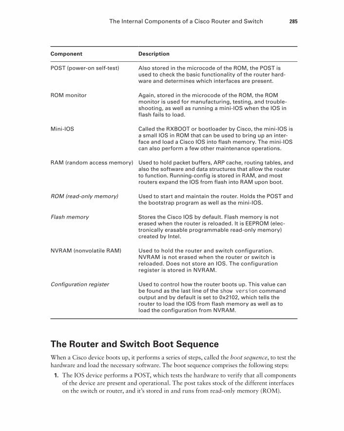
TA B LE 7.1 Cisco router components
Component Description
Bootstrap Stored in the microcode of the ROM, the bootstrap is used to bring a router up during initialization. It boots the router up and then loads the IOS.
The Internal Components of a Cisco Router and Switch 285
Component Description
POST (power-on self-test) Also stored in the microcode of the ROM, the POST is used to check the basic functionality of the router hard-ware and determines which interfaces are present.
ROM monitor Again, stored in the microcode of the ROM, the ROM monitor is used for manufacturing, testing, and trouble-shooting, as well as running a mini-IOS when the IOS in flash fails to load.
Mini-IOS Called the RXBOOT or bootloader by Cisco, the mini-IOS is a small IOS in ROM that can be used to bring up an inter-face and load a Cisco IOS into flash memory. The mini-IOS can also perform a few other maintenance operations.
RAM (random access memory) Used to hold packet buffers, ARP cache, routing tables, and also the software and data structures that allow the router to function. Running-config is stored in RAM, and most routers expand the IOS from flash into RAM upon boot.
ROM (read-only memory) Used to start and maintain the router. Holds the POST and the bootstrap program as well as the mini-IOS.
Flash memory Stores the Cisco IOS by default. Flash memory is not erased when the router is reloaded. It is EEPROM (elec-tronically erasable programmable read-only memory) created by Intel.
NVRAM (nonvolatile RAM) Used to hold the router and switch configuration. NVRAM is not erased when the router or switch is reloaded. Does not store an IOS. The configuration register is stored in NVRAM.
Configuration register Used to control how the router boots up. This value can be found as the last line of the show version command output and by default is set to 0x2102, which tells the router to load the IOS from flash memory as well as to load the configuration from NVRAM.
The Router and Switch Boot SequenceWhen a Cisco device boots up, it performs a series of steps, called the boot sequence, to test the hardware and load the necessary software. The boot sequence comprises the following steps:
1. The IOS device performs a POST, which tests the hardware to verify that all components of the device are present and operational. The post takes stock of the different interfaces on the switch or router, and it’s stored in and runs from read-only memory (ROM).
286 Chapter 7 u Managing a Cisco Internetwork
2. The bootstrap in ROM then locates and loads the Cisco IOS software by executing programs responsible for finding where each IOS program is located. Once they are found, it then loads the proper files. By default, the IOS software is loaded from flash memory in all Cisco devices.
The default order of an IOS loading from a Cisco device begins with flash, then TFTP server, and finally, ROM.
3. The IOS software then looks for a valid configuration file stored in NVRAM. This file is called startup-config and will be present only if an administrator has copied the running-config file into NVRAM.
4. If a startup-config file is found in NVRAM, the router or switch will copy it, place it in RAM, and name the file the running-config. The device will use this file to run, and the router/switch should now be operational. If no startup-config file is found in NVRAM, the router/switch reacts by broadcasting out any interface that detects carrier detect (CD) to locate a TFTP host in its search for a configuration. When that fails, which it typically does, the device will begin the setup mode configuration process. Most people don’t even realize the device has attempted this process!
Backing Up and Restoring the Cisco ConfigurationAny changes that you make to the configuration are stored in the running-config file. And if you don’t enter a copy run start command after you make a change to running-config, that change will totally disappear if the device reboots or gets powered down. As always, backups are good, so you’ll want to make another backup of the configuration information just in case the router or switch completely dies on you. Even if your machine is healthy and happy, it’s good to have a backup for reference and documentation reasons!
Next, I’ll cover how to copy the configuration of a router to a TFTP server as well as how to restore that configuration.
Backing Up the Cisco ConfigurationTo copy the configuration from an IOS device to a TFTP server, you can use either the copy running-config tftp or the copy startup-config tftp command. Either one will back up the router configuration that’s currently running in DRAM or one that’s stored in NVRAM.
Backing Up and Restoring the Cisco Configuration 287
Verifying the Current ConfigurationTo verify the configuration in DRAM, use the show running-config command (sh run for short) like this:
Router#show running-configBuilding configuration...
Current configuration : 855 bytes!version 15.0
The current configuration information indicates that the router is running version 15.0 of the IOS.
Verifying the Stored ConfigurationNext, you should check the configuration stored in NVRAM. To see this, use the show startup-config command (sh start for short) like this:
Router#sh startUsing 855 out of 524288 bytes!! Last configuration change at 04:49:14 UTC Fri Mar 5 1993!version 15.0
The first line shows you how much room your backup configuration is taking up. Here, we can see that NVRAM is about 524 KB and that only 855 bytes of it are being used. But memory is easier to reveal via the show version command when you’re using an ISR router.
If you’re not sure that the files are the same and the running-config file is what you want to go with, then use the copy running-config startup-config command. This will help you ensure that both files are in fact the same. I’ll guide you through this in the next section.
Copying the Current Configuration to NVRAMBy copying running-config to NVRAM as a backup, as shown in the following output, you ensure that your running-config will always be reloaded if the router gets rebooted. Starting in the 12.0 IOS, you’ll be prompted for the filename you want to use:
Router#copy running-config startup-configDestination filename [startup-config]?[enter]Building configuration...[OK]
288 Chapter 7 u Managing a Cisco Internetwork
The reason the filename prompt appears is that there are now so many options you can use when using the copy command—check it out:
Router#copy running-config ? flash: Copy to flash: file system ftp: Copy to ftp: file system http: Copy to http: file system https: Copy to https: file system null: Copy to null: file system nvram: Copy to nvram: file system rcp: Copy to rcp: file system running-config Update (merge with) current system configuration scp: Copy to scp: file system startup-config Copy to startup configuration syslog: Copy to syslog: file system system: Copy to system: file system tftp: Copy to tftp: file system tmpsys: Copy to tmpsys: file system
We’ll go over the copy command in more detail in the Sybex ICND2 Study Guide.
Copying the Configuration to a TFTP ServerOnce the file is copied to NVRAM, you can make a second backup to a TFTP server by using the copy running-config tftp command, or copy run tftp for short. I’m going to set the hostname to Todd before I run this command:
Todd#copy running-config tftpAddress or name of remote host []? 10.10.10.254Destination filename [todd-confg]?!!776 bytes copied in 0.800 secs (970 bytes/sec)
If you have a hostname already configured, the command will automatically use the hostname plus the extension -confg as the name of the file.
Restoring the Cisco ConfigurationWhat do you do if you’ve changed your running-config file and want to restore the configu-ration to the version in the startup-config file? The easiest way to get this done is to use the copy startup-config running-config command, or copy start run for short, but this will work only if you copied running-config into NVRAM before you made any changes! Of course, a reload of the device will work too!
If you did copy the configuration to a TFTP server as a second backup, you can restore the configuration using the copy tftp running-config command (copy tftp run for short), or
Backing Up and Restoring the Cisco Configuration 289
the copy tftp startup-config command (copy tftp start for short), as shown in the out-put below. Just so you know, the old command we used to use for this is config net:
Todd#copy tftp running-configAddress or name of remote host []?10.10.10.254Source filename []?todd-confgDestination filename[running-config]?[enter]Accessing tftp://10.10.10.254/todd-confg...Loading todd-confg from 10.10.10.254 (via FastEthernet0/0):!![OK - 776 bytes]776 bytes copied in 9.212 secs (84 bytes/sec)Todd#*Mar 7 17:53:34.071: %SYS-5-CONFIG_I: Configured from tftp://10.10.10.254/todd-confg by console
Okay, here we can see that the configuration file is an ASCII text file, meaning that before you copy the configuration stored on a TFTP server back to a router, you can make changes to the file with any text editor.
Remember that when you copy or merge a configuration from a TFTP server to a freshly erased and rebooted router’s RAM, the interfaces are shut down by default and you must manually enable each interface with the no shutdown command.
Erasing the ConfigurationTo delete the startup-config file on a Cisco router or switch, use the command erase startup-config, like this:
Todd#erase startup-configErasing the nvram filesystem will remove all configuration files! Continue? [confirm][enter][OK]Erase of nvram: complete*Mar 7 17:56:20.407: %SYS-7-NV_BLOCK_INIT: Initialized the geometry of nvramTodd#reloadSystem configuration has been modified. Save? [yes/no]:nProceed with reload? [confirm][enter] *Mar 7 17:56:31.059: %SYS-5-RELOAD: Reload requested by console. Reload Reason: Reload Command.
290 Chapter 7 u Managing a Cisco Internetwork
This command deletes the contents of NVRAM on the switch and router. If you type reload while in privileged mode and say no to saving changes, the switch or router will reload and come up into setup mode.
Configuring DHCPWe went over DHCP in Chapter 3, “Introduction to TCP/IP”, where I described how it works and what happens when there’s a conflict. At this point, you’re ready to learn how to configure DHCP on Cisco’s IOS as well as how to configure a DHCP forwarder for when your hosts don’t live on the same LAN as the DHCP server. Do you remember the four-way handshake hosts used to get an address from a server? If not, now would be a really great time to head back to Chapter 3 and thoroughly review that before moving on with this!
To configure a DHCP server for your hosts, you need the following information at minimum:
Network and mask for each LAN Network ID, also called a scope. All addresses in a subnet can be leased to hosts by default.
Reserved/excluded addresses Reserved addresses for printers, servers, routers, etc. These addresses will not be handed out to hosts. I usually reserve the first address of each subnet for the router, but you don’t have to do this.
Default router This is the router’s address for each LAN.
DNS address A list of DNS server addresses provided to hosts so they can resolve names.
Here are your configuration steps:
1. Exclude the addresses you want to reserve. The reason you do this step first is because as soon as you set a network ID, the DHCP service will start responding to client requests.
2. Create your pool for each LAN using a unique name.
3. Choose the network ID and subnet mask for the DHCP pool that the server will use to provide addresses to hosts.
4. Add the address used for the default gateway of the subnet.
5. Provide the DNS server address(es).
6. If you don’t want to use the default lease time of 24 hours, you need to set the lease time in days, hours, and minutes.
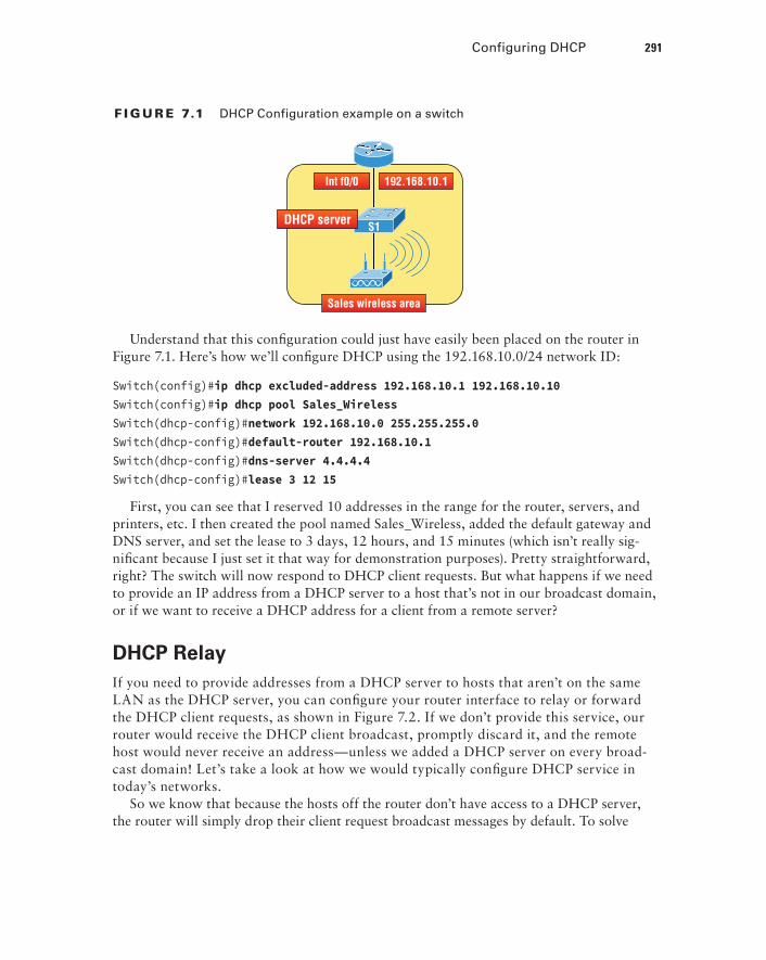
I’ll configure the switch in Figure 7.1 to be the DHCP server for the Sales Wireless LAN.
Visit ccna .gg/ch7/b for a companion MicroNugget from CBT Nuggets.
Configuring DHCP 291
F I Gu R E 7.1 DHCP Configuration example on a switch
Int f0/0 192.168.10.1
S1
Sales wireless area
DHCP server
Understand that this configuration could just have easily been placed on the router in Figure 7.1. Here’s how we’ll configure DHCP using the 192.168.10.0/24 network ID:
Switch(config)#ip dhcp excluded-address 192.168.10.1 192.168.10.10Switch(config)#ip dhcp pool Sales_WirelessSwitch(dhcp-config)#network 192.168.10.0 255.255.255.0Switch(dhcp-config)#default-router 192.168.10.1Switch(dhcp-config)#dns-server 4.4.4.4Switch(dhcp-config)#lease 3 12 15
First, you can see that I reserved 10 addresses in the range for the router, servers, and printers, etc. I then created the pool named Sales_Wireless, added the default gateway and DNS server, and set the lease to 3 days, 12 hours, and 15 minutes (which isn’t really sig-nificant because I just set it that way for demonstration purposes). Pretty straightforward, right? The switch will now respond to DHCP client requests. But what happens if we need to provide an IP address from a DHCP server to a host that’s not in our broadcast domain, or if we want to receive a DHCP address for a client from a remote server?
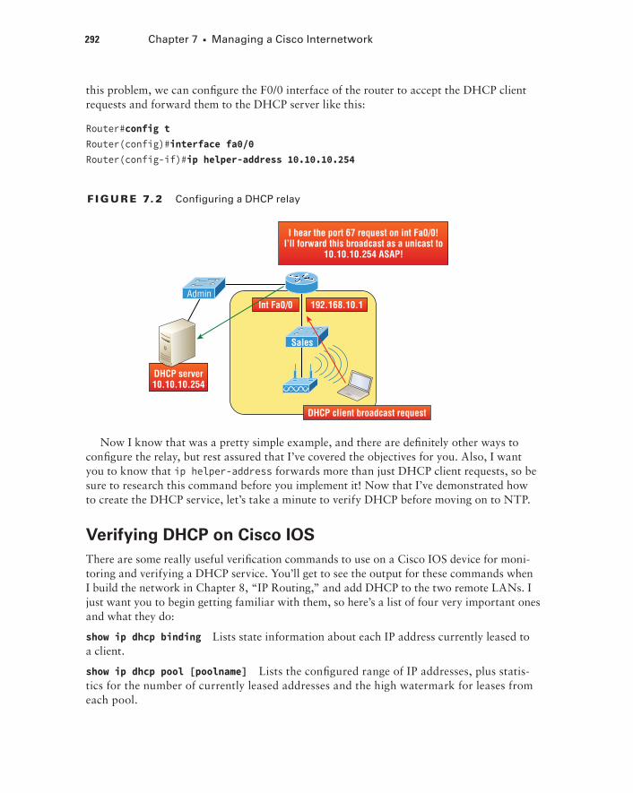
DHCP RelayIf you need to provide addresses from a DHCP server to hosts that aren’t on the same LAN as the DHCP server, you can configure your router interface to relay or forward the DHCP client requests, as shown in Figure 7.2. If we don’t provide this service, our router would receive the DHCP client broadcast, promptly discard it, and the remote host would never receive an address—unless we added a DHCP server on every broad-cast domain! Let’s take a look at how we would typically configure DHCP service in today’s networks.
So we know that because the hosts off the router don’t have access to a DHCP server, the router will simply drop their client request broadcast messages by default. To solve
292 Chapter 7 u Managing a Cisco Internetwork
this problem, we can configure the F0/0 interface of the router to accept the DHCP client requests and forward them to the DHCP server like this:
Router#config tRouter(config)#interface fa0/0Router(config-if)#ip helper-address 10.10.10.254
F I Gu R E 7. 2 Configuring a DHCP relay
Int Fa0/0 192.168.10.1
I hear the port 67 request on int Fa0/0!I’ll forward this broadcast as a unicast to
10.10.10.254 ASAP!
Sales
Admin
DHCP client broadcast request
DHCP server10.10.10.254
Now I know that was a pretty simple example, and there are definitely other ways to configure the relay, but rest assured that I’ve covered the objectives for you. Also, I want you to know that ip helper-address forwards more than just DHCP client requests, so be sure to research this command before you implement it! Now that I’ve demonstrated how to create the DHCP service, let’s take a minute to verify DHCP before moving on to NTP.
Verifying DHCP on Cisco IOSThere are some really useful verification commands to use on a Cisco IOS device for moni-toring and verifying a DHCP service. You’ll get to see the output for these commands when I build the network in Chapter 8, “IP Routing,” and add DHCP to the two remote LANs. I just want you to begin getting familiar with them, so here’s a list of four very important ones and what they do:
show ip dhcp binding Lists state information about each IP address currently leased to a client.
show ip dhcp pool [poolname] Lists the configured range of IP addresses, plus statis-tics for the number of currently leased addresses and the high watermark for leases from each pool.
Network Time Protocol (NTP) 293
show ip dhcp server statistics Lists DHCP server statistics—a lot of them!
show ip dhcp conflict If someone statically configures an IP address on a LAN and the DHCP server hands out that same address, you’ll end up with a duplicate address. This isn’t good, which is why this command is so helpful!
Again, no worries because we’ll cover these vital commands thoroughly in the next chapter.
Network Time Protocol (NTP)Network Time Protocol provides pretty much what it describes: time to all your network devices. To be more precise, NTP synchronizes clocks of computer systems over packet-switched, variable-latency data networks.
Typically you’ll have an NTP server that connects through the Internet to an atomic clock. This time can then be synchronized through the network to keep all routers, switches, servers, etc. receiving the same time information.
Correct network time within the network is important:
uu Correct time allows the tracking of events in the network in the correct order.
uu Clock synchronization is critical for the correct interpretation of events within the syslog data.
uu Clock synchronization is critical for digital certificates.
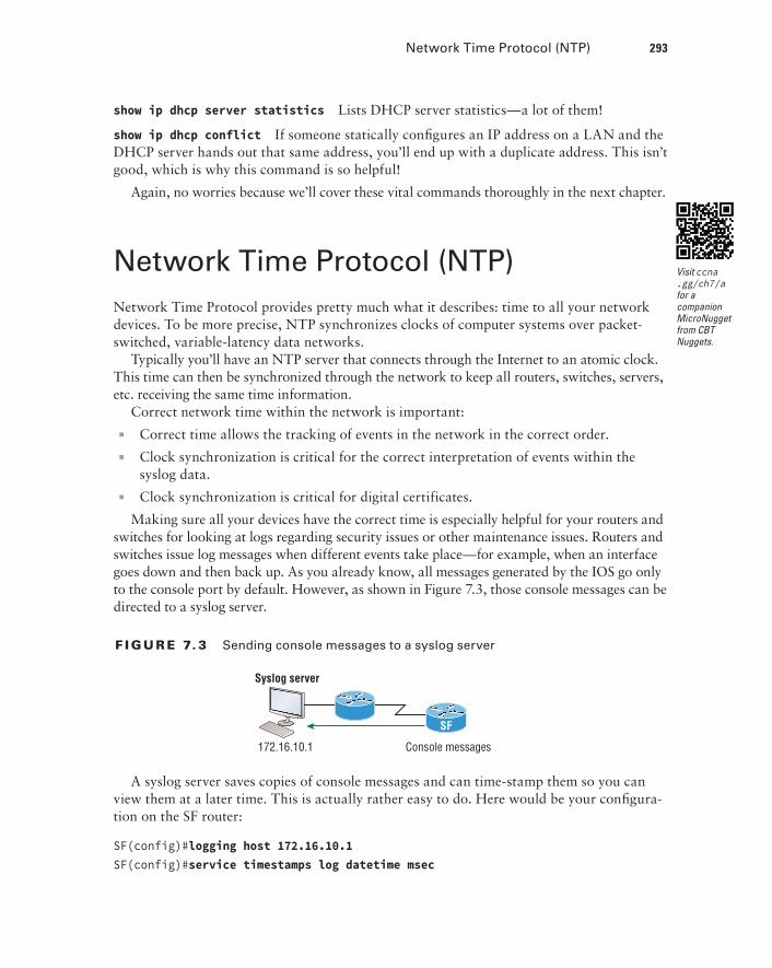
Making sure all your devices have the correct time is especially helpful for your routers and switches for looking at logs regarding security issues or other maintenance issues. Routers and switches issue log messages when different events take place—for example, when an interface goes down and then back up. As you already know, all messages generated by the IOS go only to the console port by default. However, as shown in Figure 7.3, those console messages can be directed to a syslog server.
F I Gu R E 7. 3 Sending console messages to a syslog server
Syslog server
172.16.10.1 Console messages
SF
A syslog server saves copies of console messages and can time-stamp them so you can view them at a later time. This is actually rather easy to do. Here would be your configura-tion on the SF router:
SF(config)#logging host 172.16.10.1SF(config)#service timestamps log datetime msec
Visit ccna .gg/ch7/a for a companion MicroNugget from CBT Nuggets.
294 Chapter 7 u Managing a Cisco Internetwork
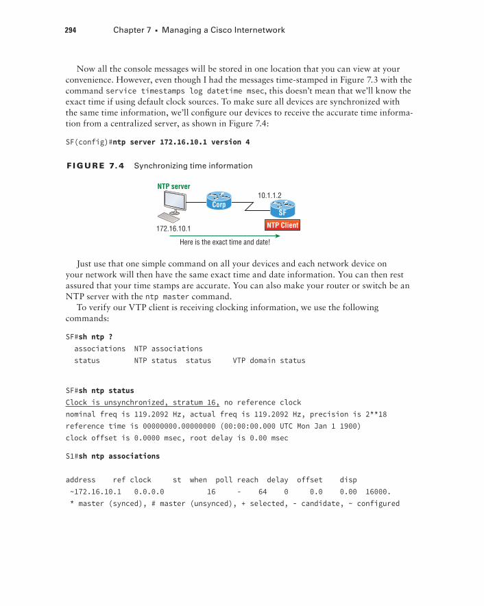
Now all the console messages will be stored in one location that you can view at your convenience. However, even though I had the messages time-stamped in Figure 7.3 with the command service timestamps log datetime msec, this doesn’t mean that we’ll know the exact time if using default clock sources. To make sure all devices are synchronized with the same time information, we’ll configure our devices to receive the accurate time informa-tion from a centralized server, as shown in Figure 7.4:
SF(config)#ntp server 172.16.10.1 version 4
F I Gu R E 7. 4 Synchronizing time information
NTP Client
Here is the exact time and date!
172.16.10.1
10.1.1.2NTP server
CorpSF
Just use that one simple command on all your devices and each network device on your network will then have the same exact time and date information. You can then rest assured that your time stamps are accurate. You can also make your router or switch be an NTP server with the ntp master command.
To verify our VTP client is receiving clocking information, we use the following commands:
SF#sh ntp ? associations NTP associations status NTP status status VTP domain status
SF#sh ntp statusClock is unsynchronized, stratum 16, no reference clocknominal freq is 119.2092 Hz, actual freq is 119.2092 Hz, precision is 2**18reference time is 00000000.00000000 (00:00:00.000 UTC Mon Jan 1 1900)clock offset is 0.0000 msec, root delay is 0.00 msec
S1#sh ntp associations
address ref clock st when poll reach delay offset disp ~172.16.10.1 0.0.0.0 16 - 64 0 0.0 0.00 16000. * master (synced), # master (unsynced), + selected, - candidate, ~ configured
Using Cisco Discovery Protocol (CDP) 295
You can see in the example that the NTP client in SF is not synchronized with the server by using the show ntp status command. The stratum value is a number from 1 to 15, and a lower stratum value indicates a higher NTP priority; 16 means there is no clocking received.
There are many other configurations of an NTP client that are available, such as authentication of NTP so a router or switch isn’t fooled into changing the time of an attack, for example.
Using Cisco Discovery Protocol (CDP)Cisco Discovery Protocol (CDP) is a proprietary protocol designed by Cisco to help adminis-trators collect information about locally attached devices. Armed with CDP, you can gather hardware and protocol information about neighbor devices, which is crucial information to have when troubleshooting and documenting the network.
Let’s start by exploring the CDP timer and CDP commands we’ll need to verify our network.
Getting CDP Timers and Holdtime InformationThe show cdp command (sh cdp for short) gives you information about two CDP global parameters that can be configured on Cisco devices:
uu CDP timer delimits how often CDP packets are transmitted out all active interfaces.
uu CDP holdtime delimits the amount of time that the device will hold packets received from neighbor devices.
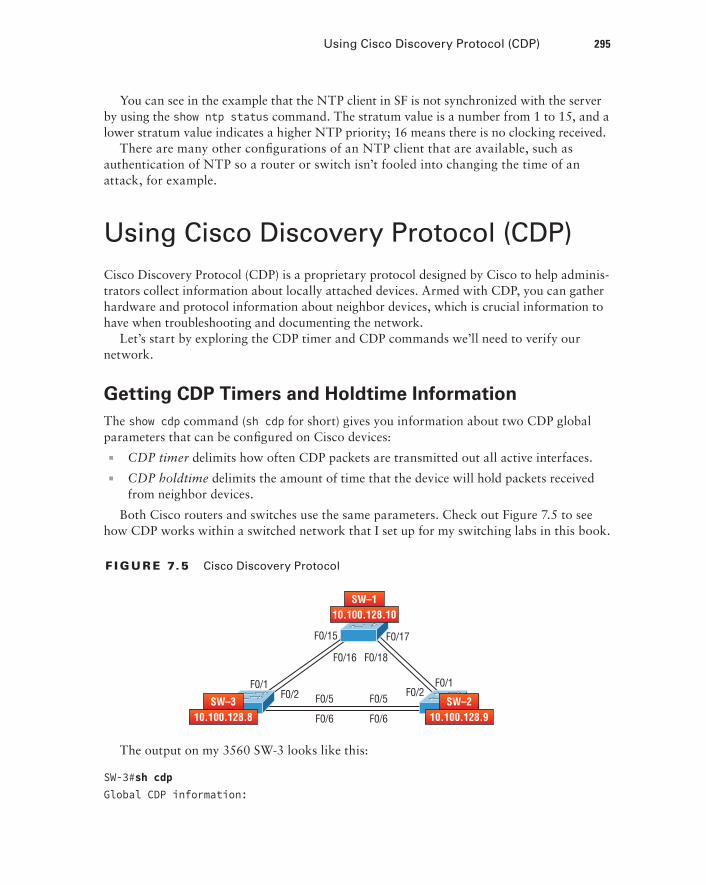
Both Cisco routers and switches use the same parameters. Check out Figure 7.5 to see how CDP works within a switched network that I set up for my switching labs in this book.
F I Gu R E 7.5 Cisco Discovery Protocol
F0/1F0/2
F0/16 F0/18
F0/15 F0/17
F0/5F0/5
F0/6F0/6
F0/2F0/1
10.100.128.9SW–2
10.100.128.10SW–1
10.100.128.8SW–3
The output on my 3560 SW-3 looks like this:
SW-3#sh cdpGlobal CDP information:
296 Chapter 7 u Managing a Cisco Internetwork
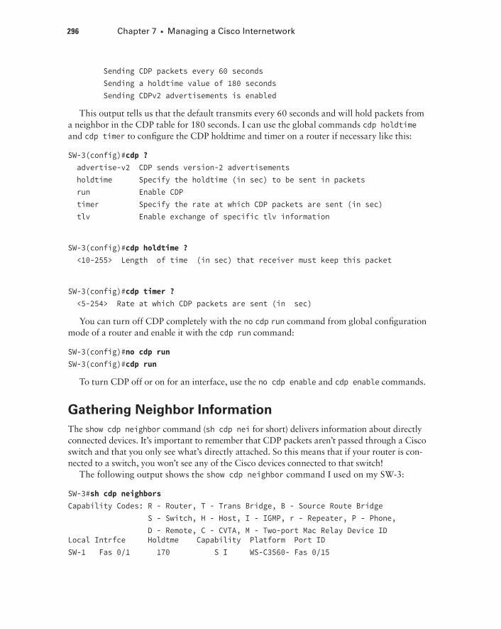
Sending CDP packets every 60 seconds Sending a holdtime value of 180 seconds Sending CDPv2 advertisements is enabled
This output tells us that the default transmits every 60 seconds and will hold packets from a neighbor in the CDP table for 180 seconds. I can use the global commands cdp holdtime and cdp timer to configure the CDP holdtime and timer on a router if necessary like this:
SW-3(config)#cdp ? advertise-v2 CDP sends version-2 advertisements holdtime Specify the holdtime (in sec) to be sent in packets run Enable CDP timer Specify the rate at which CDP packets are sent (in sec) tlv Enable exchange of specific tlv information
SW-3(config)#cdp holdtime ? <10-255> Length of time (in sec) that receiver must keep this packet
SW-3(config)#cdp timer ? <5-254> Rate at which CDP packets are sent (in sec)
You can turn off CDP completely with the no cdp run command from global configuration mode of a router and enable it with the cdp run command:
SW-3(config)#no cdp runSW-3(config)#cdp run
To turn CDP off or on for an interface, use the no cdp enable and cdp enable commands.
Gathering Neighbor InformationThe show cdp neighbor command (sh cdp nei for short) delivers information about directly connected devices. It’s important to remember that CDP packets aren’t passed through a Cisco switch and that you only see what’s directly attached. So this means that if your router is con-nected to a switch, you won’t see any of the Cisco devices connected to that switch!
The following output shows the show cdp neighbor command I used on my SW-3:
SW-3#sh cdp neighborsCapability Codes: R - Router, T - Trans Bridge, B - Source Route Bridge S - Switch, H - Host, I - IGMP, r - Repeater, P - Phone, D - Remote, C - CVTA, M - Two-port Mac Relay Device ID Local Intrfce Holdtme Capability Platform Port IDSW-1 Fas 0/1 170 S I WS-C3560- Fas 0/15
Using Cisco Discovery Protocol (CDP) 297
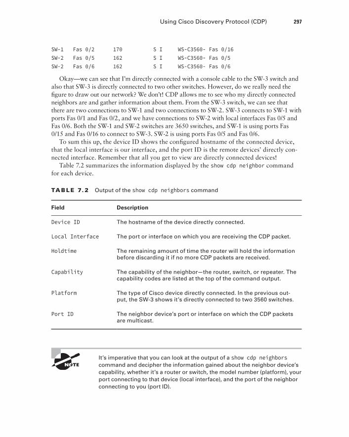
SW-1 Fas 0/2 170 S I WS-C3560- Fas 0/16SW-2 Fas 0/5 162 S I WS-C3560- Fas 0/5SW-2 Fas 0/6 162 S I WS-C3560- Fas 0/6
Okay—we can see that I’m directly connected with a console cable to the SW-3 switch and also that SW-3 is directly connected to two other switches. However, do we really need the figure to draw out our network? We don’t! CDP allows me to see who my directly connected neighbors are and gather information about them. From the SW-3 switch, we can see that there are two connections to SW-1 and two connections to SW-2. SW-3 connects to SW-1 with ports Fas 0/1 and Fas 0/2, and we have connections to SW-2 with local interfaces Fas 0/5 and Fas 0/6. Both the SW-1 and SW-2 switches are 3650 switches, and SW-1 is using ports Fas 0/15 and Fas 0/16 to connect to SW-3. SW-2 is using ports Fas 0/5 and Fas 0/6.
To sum this up, the device ID shows the configured hostname of the connected device, that the local interface is our interface, and the port ID is the remote devices’ directly con-nected interface. Remember that all you get to view are directly connected devices!
Table 7.2 summarizes the information displayed by the show cdp neighbor command for each device.
TA B LE 7. 2 Output of the show cdp neighbors command
Field Description
Device ID The hostname of the device directly connected.
Local Interface The port or interface on which you are receiving the CDP packet.
Holdtime The remaining amount of time the router will hold the information before discarding it if no more CDP packets are received.
Capability The capability of the neighbor—the router, switch, or repeater. The capability codes are listed at the top of the command output.
Platform The type of Cisco device directly connected. In the previous out-put, the SW-3 shows it’s directly connected to two 3560 switches.
Port ID The neighbor device’s port or interface on which the CDP packets are multicast.
It’s imperative that you can look at the output of a show cdp neighbors command and decipher the information gained about the neighbor device’s capability, whether it’s a router or switch, the model number (platform), your port connecting to that device (local interface), and the port of the neighbor connecting to you (port ID).
298 Chapter 7 u Managing a Cisco Internetwork
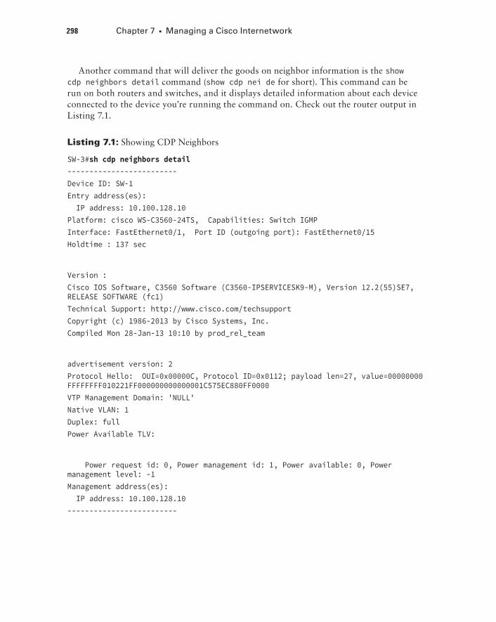
Another command that will deliver the goods on neighbor information is the show cdp neighbors detail command (show cdp nei de for short). This command can be run on both routers and switches, and it displays detailed information about each device connected to the device you’re running the command on. Check out the router output in Listing 7.1.
Listing 7.1: Showing CDP Neighbors
SW-3#sh cdp neighbors detail-------------------------Device ID: SW-1Entry address(es): IP address: 10.100.128.10Platform: cisco WS-C3560-24TS, Capabilities: Switch IGMPInterface: FastEthernet0/1, Port ID (outgoing port): FastEthernet0/15Holdtime : 137 sec
Version :Cisco IOS Software, C3560 Software (C3560-IPSERVICESK9-M), Version 12.2(55)SE7, RELEASE SOFTWARE (fc1)Technical Support: http://www.cisco.com/techsupportCopyright (c) 1986-2013 by Cisco Systems, Inc.Compiled Mon 28-Jan-13 10:10 by prod_rel_team
advertisement version: 2Protocol Hello: OUI=0x00000C, Protocol ID=0x0112; payload len=27, value=00000000FFFFFFFF010221FF000000000000001C575EC880FF0000VTP Management Domain: 'NULL'Native VLAN: 1Duplex: fullPower Available TLV:
Power request id: 0, Power management id: 1, Power available: 0, Power management level: -1Management address(es): IP address: 10.100.128.10-------------------------
Using Cisco Discovery Protocol (CDP) 299
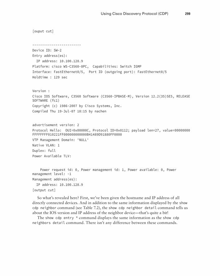
[ouput cut]
-------------------------Device ID: SW-2Entry address(es): IP address: 10.100.128.9Platform: cisco WS-C3560-8PC, Capabilities: Switch IGMPInterface: FastEthernet0/5, Port ID (outgoing port): FastEthernet0/5Holdtime : 129 sec
Version :Cisco IOS Software, C3560 Software (C3560-IPBASE-M), Version 12.2(35)SE5, RELEASE SOFTWARE (fc1)Copyright (c) 1986-2007 by Cisco Systems, Inc.Compiled Thu 19-Jul-07 18:15 by nachen
advertisement version: 2Protocol Hello: OUI=0x00000C, Protocol ID=0x0112; payload len=27, value=00000000FFFFFFFF010221FF000000000000B41489D91880FF0000VTP Management Domain: 'NULL'Native VLAN: 1Duplex: fullPower Available TLV:
Power request id: 0, Power management id: 1, Power available: 0, Power management level: -1Management address(es): IP address: 10.100.128.9[output cut]
So what’s revealed here? First, we’ve been given the hostname and IP address of all directly connected devices. And in addition to the same information displayed by the show cdp neighbor command (see Table 7.2), the show cdp neighbor detail command tells us about the IOS version and IP address of the neighbor device—that’s quite a bit!
The show cdp entry * command displays the same information as the show cdp neighbors detail command. There isn’t any difference between these commands.
300 Chapter 7 u Managing a Cisco Internetwork
CDP Can Save Lives!
Karen has just been hired as a senior network consultant at a large hospital in Dallas, Texas, so she’s expected to be able to take care of any problem that rears its ugly head. As if that weren’t enough pressure, she also has to worry about the horrid possibility that people won’t receive correct health care solutions—even the correct medications—if the network goes down. Talk about a potential life-or-death situation!
But Karen is confident and begins her job optimistically. Of course, it’s not long before the network reveals that it has a few problems. Unfazed, she asks one of the junior administra-tors for a network map so she can troubleshoot the network. This person tells her that the old senior administrator, who she replaced, had them with him and now no one can find them. The sky begins to darken!
Doctors are calling every couple of minutes because they can’t get the necessary infor-mation they need to take care of their patients. What should she do?
It’s CDP to the rescue! And it’s a gift that this hospital happens to be running Cisco routers and switches exclusively, because CDP is enabled by default on all Cisco devices. Karen is also in luck because the disgruntled former administrator didn’t turn off CDP on any devices before he left!
So all Karen has to do now is to use the show cdp neighbor detail command to find all the information she needs about each device to help draw out the hospital network, bringing it back up to speed so the personnel who rely upon it can get on to the important business of saving lives!
The only snag for you nailing this in your own network is if you don’t know the passwords of all those devices. Your only hope then is to somehow find out the access passwords or to perform password recovery on them.
So, use CDP—you never know when you may end up saving someone’s life.
By the way, this is a true story!
Documenting a Network Topology Using CDPWith that moving real-life scenario in mind, I’m now going to show you how to document a sample network by using CDP. You’ll learn to determine the appropriate router types, inter-face types, and IP addresses of various interfaces using only CDP commands and the show running-config command. And you can only console into the Lab_A router to document
Using Cisco Discovery Protocol (CDP) 301
the network. You’ll have to assign any remote routers the next IP address in each range. We’ll use a different figure for this example—Figure 7.6— to help us to complete the neces-sary documentation.
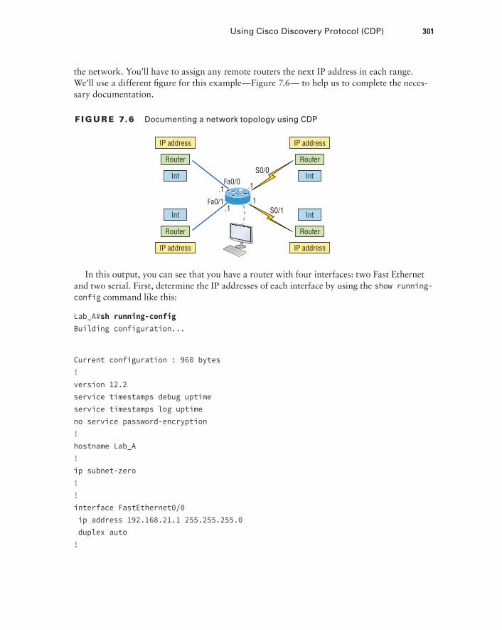
F I Gu R E 7.6 Documenting a network topology using CDP
.1
Int
Router
IP address
Int
Router
IP address
Int
Router
IP address
Int
Router
IP address
Fa0/0
Fa0/1S0/1
S0/0
.1
.1.1
In this output, you can see that you have a router with four interfaces: two Fast Ethernet and two serial. First, determine the IP addresses of each interface by using the show running-config command like this:
Lab_A#sh running-configBuilding configuration...
Current configuration : 960 bytes!version 12.2service timestamps debug uptimeservice timestamps log uptimeno service password-encryption!hostname Lab_A!ip subnet-zero!!interface FastEthernet0/0 ip address 192.168.21.1 255.255.255.0 duplex auto!
302 Chapter 7 u Managing a Cisco Internetwork
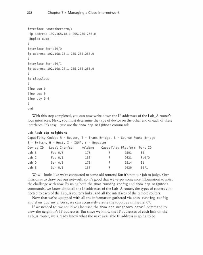
interface FastEthernet0/1 ip address 192.168.18.1 255.255.255.0 duplex auto!interface Serial0/0ip address 192.168.23.1 255.255.255.0!interface Serial0/1ip address 192.168.28.1 255.255.255.0!ip classless!line con 0line aux 0line vty 0 4!end
With this step completed, you can now write down the IP addresses of the Lab_A router’s four interfaces. Next, you must determine the type of device on the other end of each of these interfaces. It’s easy—just use the show cdp neighbors command:
Lab_A#sh cdp neighborsCapability Codes: R - Router, T - Trans Bridge, B - Source Route BridgeS - Switch, H - Host, I - IGMP, r - RepeaterDevice ID Local Intrfce Holdtme Capability Platform Port IDLab_B Fas 0/0 178 R 2501 E0Lab_C Fas 0/1 137 R 2621 Fa0/0Lab_D Ser 0/0 178 R 2514 S1Lab_E Ser 0/1 137 R 2620 S0/1
Wow—looks like we’re connected to some old routers! But it’s not our job to judge. Our mission is to draw out our network, so it’s good that we’ve got some nice information to meet the challenge with now. By using both the show running-config and show cdp neighbors commands, we know about all the IP addresses of the Lab_A router, the types of routers con-nected to each of the Lab_A router’s links, and all the interfaces of the remote routers.
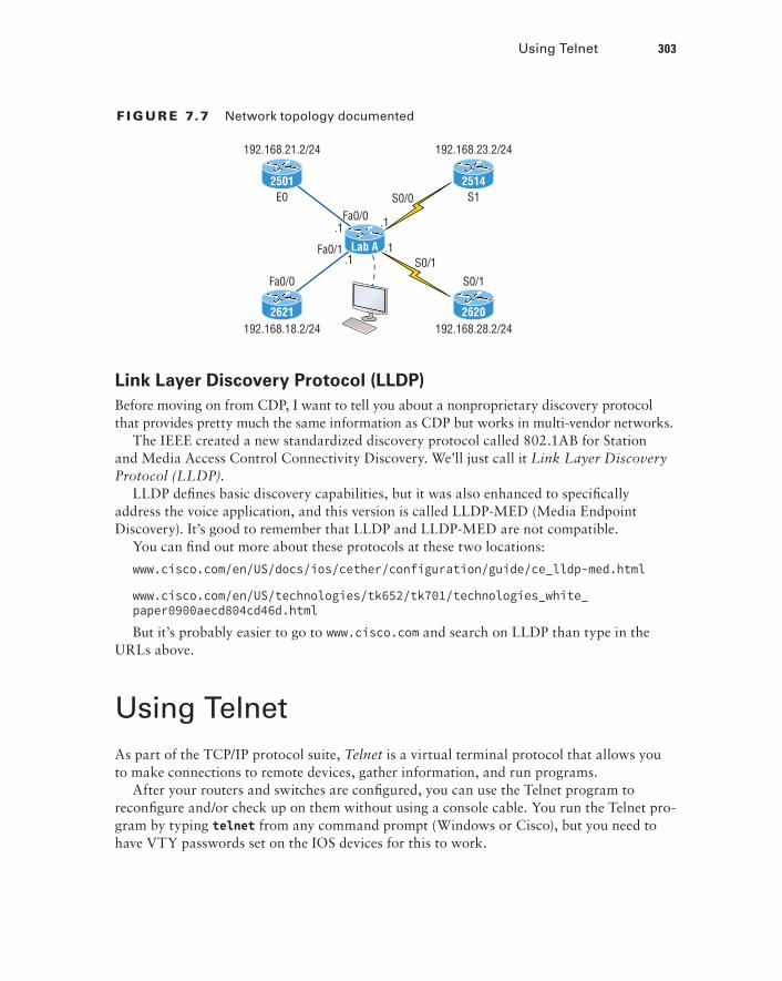
Now that we’re equipped with all the information gathered via show running-config and show cdp neighbors, we can accurately create the topology in Figure 7.7.
If we needed to, we could’ve also used the show cdp neighbors detail command to view the neighbor’s IP addresses. But since we know the IP addresses of each link on the Lab_A router, we already know what the next available IP address is going to be.
Using Telnet 303
F I Gu R E 7.7 Network topology documented
.1Fa0/0
Fa0/1S0/1
S0/0
.1
.1.1
192.168.21.2/24 192.168.23.2/24
E0 S1
192.168.18.2/24 192.168.28.2/24
Fa0/0 S0/1
Lab A
2501 2514
2621 2620
Link Layer Discovery Protocol (LLDP)Before moving on from CDP, I want to tell you about a nonproprietary discovery protocol that provides pretty much the same information as CDP but works in multi-vendor networks.
The IEEE created a new standardized discovery protocol called 802.1AB for Station and Media Access Control Connectivity Discovery. We’ll just call it Link Layer Discovery Protocol (LLDP).
LLDP defines basic discovery capabilities, but it was also enhanced to specifically address the voice application, and this version is called LLDP-MED (Media Endpoint Discovery). It’s good to remember that LLDP and LLDP-MED are not compatible.
You can find out more about these protocols at these two locations:
www.cisco.com/en/US/docs/ios/cether/configuration/guide/ce_lldp-med.html
www.cisco.com/en/US/technologies/tk652/tk701/technologies_white_paper0900aecd804cd46d.html
But it’s probably easier to go to www.cisco.com and search on LLDP than type in the URLs above.
Using TelnetAs part of the TCP/IP protocol suite, Telnet is a virtual terminal protocol that allows you to make connections to remote devices, gather information, and run programs.
After your routers and switches are configured, you can use the Telnet program to reconfigure and/or check up on them without using a console cable. You run the Telnet pro-gram by typing telnet from any command prompt (Windows or Cisco), but you need to have VTY passwords set on the IOS devices for this to work.
304 Chapter 7 u Managing a Cisco Internetwork
Remember, you can’t use CDP to gather information about routers and switches that aren’t directly connected to your device. But you can use the Telnet application to connect to your neighbor devices and then run CDP on those remote devices to get information on them.
You can issue the telnet command from any router or switch prompt. Below, I’m trying to telnet from switch 1 to switch 3:
SW-1#telnet 10.100.128.8Trying 10.100.128.8 ... Open
Password required, but none set
[Connection to 10.100.128.8 closed by foreign host]
Oops—clearly, I didn’t set my passwords—how embarrassing! Remember that the VTY ports are default configured as login, meaning that we have to either set the VTY passwords or use the no login command. If you need to review the process of setting passwords, take a quick look back in Chapter 6, “Cisco’s Internetworking Operating System (IOS).”
If you can’t telnet into a device, it could be that the password on the remote device hasn’t been set. It’s also quite possible that an access control list is filtering the Telnet session.
On a Cisco device, you don’t need to use the telnet command; you can just type in an IP address from a command prompt and the router will assume that you want to telnet to the device. Here’s how that looks using just the IP address:
SW-1#10.100.128.8Trying 10.100.128.8... Open
Password required, but none set
[Connection to 10.100.128.8 closed by foreign host]SW-1#
Now would be a great time to set those VTY passwords on the SW-3 that I want to telnet into. Here’s what I did on the switch named SW-3:
SW-3(config)#line vty 0 15SW-3(config-line)#loginSW-3(config-line)#password telnetSW-3(config-line)#loginSW-3(config-line)#^Z
Using Telnet 305
Now let’s try this again. This time, I’m connecting to SW-3 from the SW-1 console:
SW-1#10.100.128.8Trying 10.100.128.8 ... Open
User Access Verification
Password:SW-3>
Remember that the VTY password is the user-mode password, not the enable-mode password. Watch what happens when I try to go into privileged mode after telnetting into the switch:
SW-3>en% No password setSW-3>
It’s totally slamming the door in my face, which happens to be a really nice security fea-ture! After all, you don’t want just anyone telnetting into your device and typing the enable command to get into privileged mode now, do you? You’ve got to set your enable-mode pass-word or enable secret password to use Telnet to configure remote devices.
When you telnet into a remote device, you won’t see console messages by default. For example, you will not see debugging output. To allow console messages to be sent to your Telnet session, use the terminal monitor command.
Using the next group of examples, I’ll show you how to telnet into multiple devices simultaneously as well as how to use hostnames instead of IP addresses.
Telnetting into Multiple Devices SimultaneouslyIf you telnet to a router or switch, you can end the connection by typing exit at any time. But what if you want to keep your connection to a remote device going while still coming back to your original router console? To do that, you can press the Ctrl+Shift+6 key combi-nation, release it, and then press X.
Here’s an example of connecting to multiple devices from my SW-1 console:
SW-1#10.100.128.8Trying 10.100.128.8... Open
306 Chapter 7 u Managing a Cisco Internetwork
User Access Verification
Password:SW-3>Ctrl+Shift+6SW-1#
Here you can see that I telnetted to SW-1 and then typed the password to enter user mode. Next, I pressed Ctrl+Shift+6, then X, but you won’t see any of that because it doesn’t show on the screen output. Notice that my command prompt now has me back at the SW-1 switch.
Now let’s run through some verification commands.
Checking Telnet ConnectionsIf you want to view the connections from your router or switch to a remote device, just use the show sessions command. In this case, I’ve telnetted into both the SW-3 and SW-2 switches from SW1:
SW-1#sh sessionsConn Host Address Byte Idle Conn Name 1 10.100.128.9 10.100.128.9 0 10.100.128.9* 2 10.100.128.8 10.100.128.8 0 10.100.128.8SW-1#
See that asterisk (*) next to connection 2? It means that session 2 was the last session I connected to. You can return to your last session by pressing Enter twice. You can also return to any session by typing the number of the connection and then Enter.
Checking Telnet UsersYou can reveal all active consoles and VTY ports in use on your router with the show users command:
SW-1#sh users Line User Host(s) Idle Location* 0 con 0 10.100.128.9 00:00:01 10.100.128.8 00:01:06
In the command’s output, con represents the local console, and we can see that the con-sole session is connected to two remote IP addresses—in other words, two devices.
Closing Telnet SessionsYou can end Telnet sessions a few different ways. Typing exit or disconnect are probably the two quickest and easiest.
Resolving Hostnames 307
To end a session from a remote device, use the exit command:
SW-3>exit[Connection to 10.100.128.8 closed by foreign host]SW-1#
To end a session from a local device, use the disconnect command:
SW-1#sh sessionConn Host Address Byte Idle Conn Name *2 10.100.128.9 10.100.128.9 0 10.100.128.9SW-1#disconnect ? <2-2> The number of an active network connection qdm Disconnect QDM web-based clients ssh Disconnect an active SSH connectionSW-1#disconnect 2Closing connection to 10.100.128.9 [confirm][enter]
In this example, I used session number 2 because that was the connection I wanted to conclude. As demonstrated, you can use the show sessions command to see the connec-tion number.
Resolving HostnamesIf you want to use a hostname instead of an IP address to connect to a remote device, the device that you’re using to make the connection must be able to translate the hostname to an IP address.
There are two ways to resolve hostnames to IP addresses. The first is by building a host table on each router, and the second is to build a Domain Name System (DNS) server. The latter method is similar to creating a dynamic host table assuming that you’re dealing with dynamic DNS.
Building a Host TableAn important factor to remember is that although a host table provides name resolution, it does that only on the specific router that it was built upon. The command you use to build a host table on a router looks this:
ip host host_name [tcp_port_number] ip_address
The default is TCP port number 23, but you can create a session using Telnet with a different TCP port number if you want. You can also assign up to eight IP addresses to a hostname.
308 Chapter 7 u Managing a Cisco Internetwork
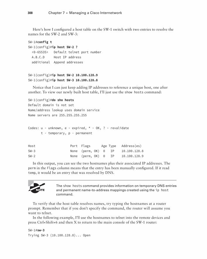
Here’s how I configured a host table on the SW-1 switch with two entries to resolve the names for the SW-2 and SW-3:
SW-1#config tSW-1(config)#ip host SW-2 ? <0-65535> Default telnet port number A.B.C.D Host IP address additional Append addresses
SW-1(config)#ip host SW-2 10.100.128.9SW-1(config)#ip host SW-3 10.100.128.8
Notice that I can just keep adding IP addresses to reference a unique host, one after another. To view our newly built host table, I’ll just use the show hosts command:
SW-1(config)#do sho hostsDefault domain is not setName/address lookup uses domain serviceName servers are 255.255.255.255
Codes: u - unknown, e - expired, * - OK, ? - revalidate t - temporary, p - permanent
Host Port Flags Age Type Address(es)SW-3 None (perm, OK) 0 IP 10.100.128.8SW-2 None (perm, OK) 0 IP 10.100.128.9
In this output, you can see the two hostnames plus their associated IP addresses. The perm in the Flags column means that the entry has been manually configured. If it read temp, it would be an entry that was resolved by DNS.
The show hosts command provides information on temporary DNS entries and permanent name-to-address mappings created using the ip host command.
To verify that the host table resolves names, try typing the hostnames at a router prompt. Remember that if you don’t specify the command, the router will assume you want to telnet.
In the following example, I’ll use the hostnames to telnet into the remote devices and press Ctrl+Shift+6 and then X to return to the main console of the SW-1 router:
SW-1#sw-3Trying SW-3 (10.100.128.8)... Open
Resolving Hostnames 309
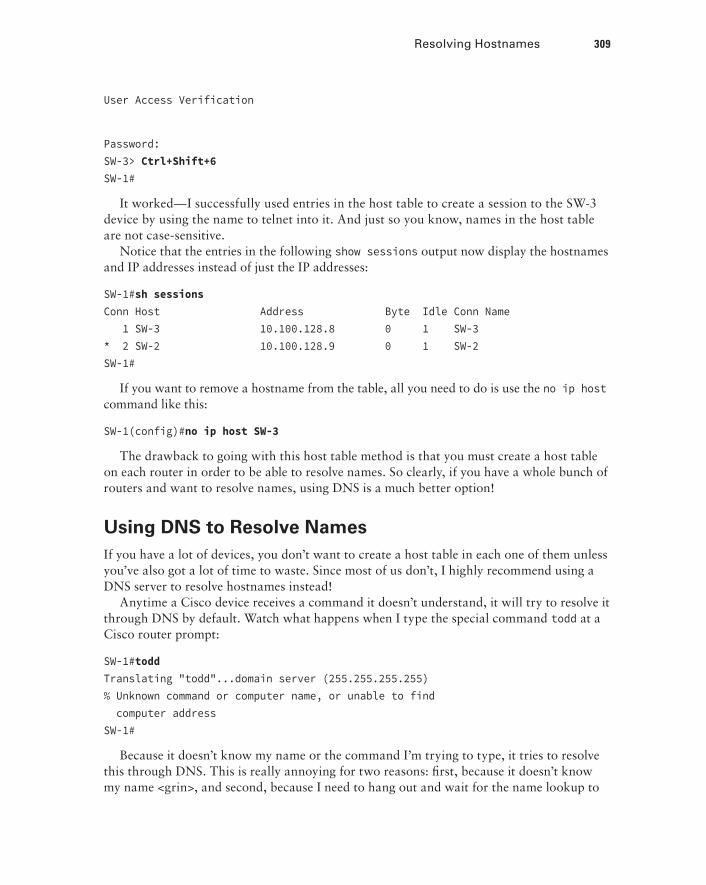
User Access Verification
Password:SW-3> Ctrl+Shift+6SW-1#
It worked—I successfully used entries in the host table to create a session to the SW-3 device by using the name to telnet into it. And just so you know, names in the host table are not case-sensitive.
Notice that the entries in the following show sessions output now display the hostnames and IP addresses instead of just the IP addresses:
SW-1#sh sessionsConn Host Address Byte Idle Conn Name 1 SW-3 10.100.128.8 0 1 SW-3* 2 SW-2 10.100.128.9 0 1 SW-2SW-1#
If you want to remove a hostname from the table, all you need to do is use the no ip host command like this:
SW-1(config)#no ip host SW-3
The drawback to going with this host table method is that you must create a host table on each router in order to be able to resolve names. So clearly, if you have a whole bunch of routers and want to resolve names, using DNS is a much better option!
Using DNS to Resolve NamesIf you have a lot of devices, you don’t want to create a host table in each one of them unless you’ve also got a lot of time to waste. Since most of us don’t, I highly recommend using a DNS server to resolve hostnames instead!
Anytime a Cisco device receives a command it doesn’t understand, it will try to resolve it through DNS by default. Watch what happens when I type the special command todd at a Cisco router prompt:
SW-1#toddTranslating "todd"...domain server (255.255.255.255)% Unknown command or computer name, or unable to find computer addressSW-1#
Because it doesn’t know my name or the command I’m trying to type, it tries to resolve this through DNS. This is really annoying for two reasons: first, because it doesn’t know my name <grin>, and second, because I need to hang out and wait for the name lookup to
310 Chapter 7 u Managing a Cisco Internetwork
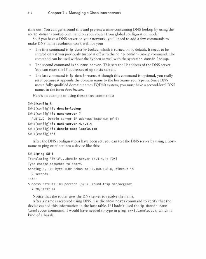
time out. You can get around this and prevent a time-consuming DNS lookup by using the no ip domain-lookup command on your router from global configuration mode.
So if you have a DNS server on your network, you’ll need to add a few commands to make DNS name resolution work well for you:
uu The first command is ip domain-lookup, which is turned on by default. It needs to be entered only if you previously turned it off with the no ip domain-lookup command. The command can be used without the hyphen as well with the syntax ip domain lookup.
uu The second command is ip name-server. This sets the IP address of the DNS server. You can enter the IP addresses of up to six servers.
uu The last command is ip domain-name. Although this command is optional, you really set it because it appends the domain name to the hostname you type in. Since DNS uses a fully qualified domain name (FQDN) system, you must have a second-level DNS name, in the form domain.com.
Here’s an example of using these three commands:
SW-1#config tSW-1(config)#ip domain-lookupSW-1(config)#ip name-server ? A.B.C.D Domain server IP address (maximum of 6)SW-1(config)#ip name-server 4.4.4.4SW-1(config)#ip domain-name lammle.comSW-1(config)#^Z
After the DNS configurations have been set, you can test the DNS server by using a host-name to ping or telnet into a device like this:
SW-1#ping SW-3Translating "SW-3"...domain server (4.4.4.4) [OK]Type escape sequence to abort.Sending 5, 100-byte ICMP Echos to 10.100.128.8, timeout is 2 seconds:!!!!!Success rate is 100 percent (5/5), round-trip min/avg/max = 28/31/32 ms
Notice that the router uses the DNS server to resolve the name.After a name is resolved using DNS, use the show hosts command to verify that the
device cached this information in the host table. If I hadn’t used the ip domain-name lammle.com command, I would have needed to type in ping sw-3.lammle.com, which is kind of a hassle.
Checking Network Connectivity and Troubleshooting 311
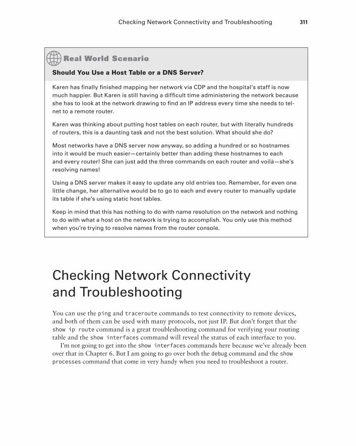
Should You use a host Table or a DNS Server?
Karen has finally finished mapping her network via CDP and the hospital’s staff is now much happier. But Karen is still having a difficult time administering the network because she has to look at the network drawing to find an IP address every time she needs to tel-net to a remote router.
Karen was thinking about putting host tables on each router, but with literally hundreds of routers, this is a daunting task and not the best solution. What should she do?
Most networks have a DNS server now anyway, so adding a hundred or so hostnames into it would be much easier—certainly better than adding these hostnames to each and every router! She can just add the three commands on each router and voilà—she’s resolving names!
Using a DNS server makes it easy to update any old entries too. Remember, for even one little change, her alternative would be to go to each and every router to manually update its table if she’s using static host tables.
Keep in mind that this has nothing to do with name resolution on the network and nothing to do with what a host on the network is trying to accomplish. You only use this method when you’re trying to resolve names from the router console.
Checking Network Connectivity and TroubleshootingYou can use the ping and traceroute commands to test connectivity to remote devices, and both of them can be used with many protocols, not just IP. But don’t forget that the show ip route command is a great troubleshooting command for verifying your routing table and the show interfaces command will reveal the status of each interface to you.
I’m not going to get into the show interfaces commands here because we’ve already been over that in Chapter 6. But I am going to go over both the debug command and the show processes command that come in very handy when you need to troubleshoot a router.
312 Chapter 7 u Managing a Cisco Internetwork
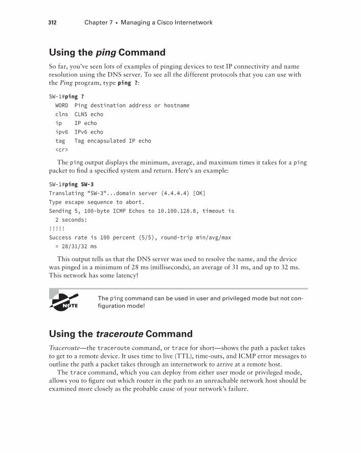
Using the ping CommandSo far, you’ve seen lots of examples of pinging devices to test IP connectivity and name resolution using the DNS server. To see all the different protocols that you can use with the Ping program, type ping ?:
SW-1#ping ? WORD Ping destination address or hostname clns CLNS echo ip IP echo ipv6 IPv6 echo tag Tag encapsulated IP echo <cr>
The ping output displays the minimum, average, and maximum times it takes for a ping packet to find a specified system and return. Here’s an example:
SW-1#ping SW-3Translating "SW-3"...domain server (4.4.4.4) [OK]Type escape sequence to abort.Sending 5, 100-byte ICMP Echos to 10.100.128.8, timeout is 2 seconds:!!!!!Success rate is 100 percent (5/5), round-trip min/avg/max = 28/31/32 ms
This output tells us that the DNS server was used to resolve the name, and the device was pinged in a minimum of 28 ms (milliseconds), an average of 31 ms, and up to 32 ms. This network has some latency!
The ping command can be used in user and privileged mode but not con-figuration mode!
Using the traceroute CommandTraceroute—the traceroute command, or trace for short—shows the path a packet takes to get to a remote device. It uses time to live (TTL), time-outs, and ICMP error messages to outline the path a packet takes through an internetwork to arrive at a remote host.
The trace command, which you can deploy from either user mode or privileged mode, allows you to figure out which router in the path to an unreachable network host should be examined more closely as the probable cause of your network’s failure.
Checking Network Connectivity and Troubleshooting 313
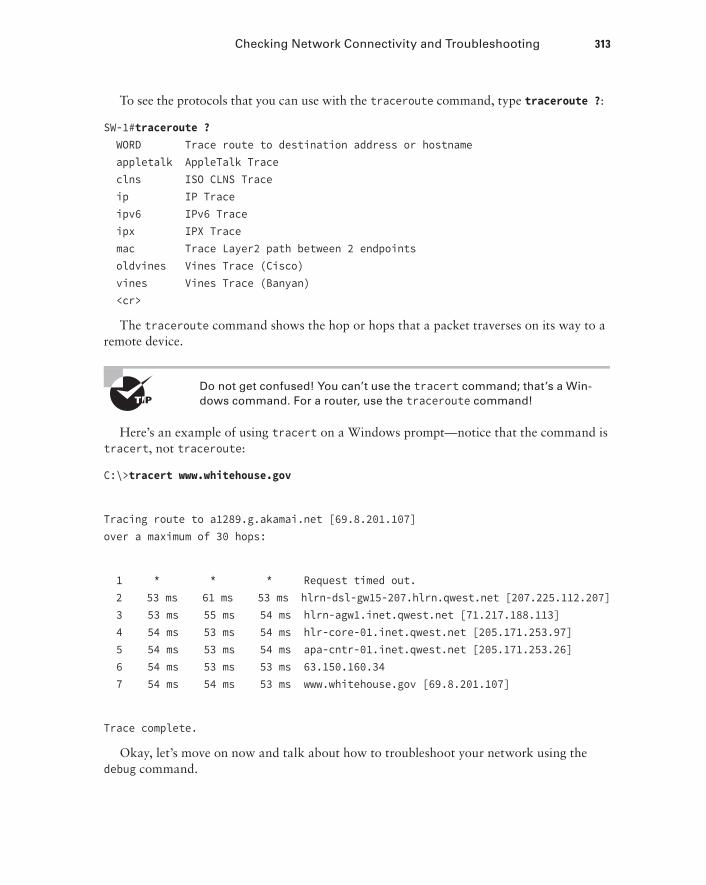
To see the protocols that you can use with the traceroute command, type traceroute ?:
SW-1#traceroute ? WORD Trace route to destination address or hostname appletalk AppleTalk Trace clns ISO CLNS Trace ip IP Trace ipv6 IPv6 Trace ipx IPX Trace mac Trace Layer2 path between 2 endpoints oldvines Vines Trace (Cisco) vines Vines Trace (Banyan) <cr>
The traceroute command shows the hop or hops that a packet traverses on its way to a remote device.
Do not get confused! You can’t use the tracert command; that’s a Win-dows command. For a router, use the traceroute command!
Here’s an example of using tracert on a Windows prompt—notice that the command is tracert, not traceroute:
C:\>tracert www.whitehouse.gov
Tracing route to a1289.g.akamai.net [69.8.201.107]over a maximum of 30 hops:
1 * * * Request timed out. 2 53 ms 61 ms 53 ms hlrn-dsl-gw15-207.hlrn.qwest.net [207.225.112.207] 3 53 ms 55 ms 54 ms hlrn-agw1.inet.qwest.net [71.217.188.113] 4 54 ms 53 ms 54 ms hlr-core-01.inet.qwest.net [205.171.253.97] 5 54 ms 53 ms 54 ms apa-cntr-01.inet.qwest.net [205.171.253.26] 6 54 ms 53 ms 53 ms 63.150.160.34 7 54 ms 54 ms 53 ms www.whitehouse.gov [69.8.201.107]
Trace complete.
Okay, let’s move on now and talk about how to troubleshoot your network using the debug command.
314 Chapter 7 u Managing a Cisco Internetwork
DebuggingDebug is a useful troubleshooting command that’s available from the privileged exec mode of Cisco IOS. It’s used to display information about various router operations and the related traffic generated or received by the router, plus any error messages.
Even though it’s a helpful, informative tool, there are a few important facts that you need to know about it. Debug is regarded as a very high-overhead task because it can consume a huge amount of resources and the router is forced to process-switch the packets being debugged. So you don’t just use debug as a monitoring tool—it’s meant to be used for a short period of time and only as a troubleshooting tool. It’s highly useful for discovering some truly significant facts about both working and faulty software and/or hardware components, but remember to limit its use as the beneficial troubleshooting tool it’s designed to be.
Because debugging output takes priority over other network traffic, and because the debug all command generates more output than any other debug command, it can severely diminish the router’s performance—even render it unusable! Because of this, it’s nearly always best to use more specific debug commands.
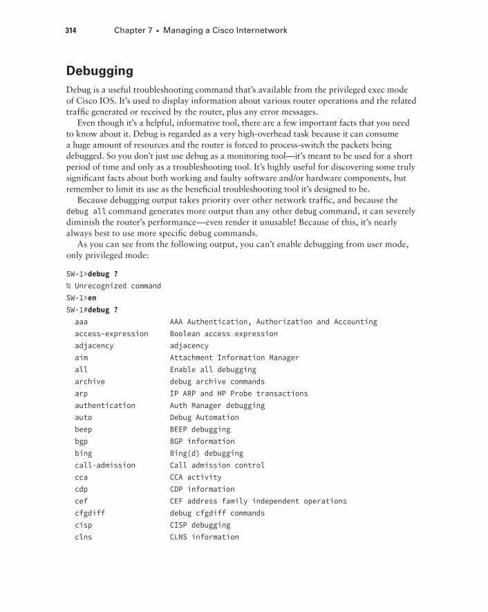
As you can see from the following output, you can’t enable debugging from user mode, only privileged mode:
SW-1>debug ?% Unrecognized commandSW-1>enSW-1#debug ? aaa AAA Authentication, Authorization and Accounting access-expression Boolean access expression adjacency adjacency aim Attachment Information Manager all Enable all debugging archive debug archive commands arp IP ARP and HP Probe transactions authentication Auth Manager debugging auto Debug Automation beep BEEP debugging bgp BGP information bing Bing(d) debugging call-admission Call admission control cca CCA activity cdp CDP information cef CEF address family independent operations cfgdiff debug cfgdiff commands cisp CISP debugging clns CLNS information
Checking Network Connectivity and Troubleshooting 315
cluster Cluster information cmdhd Command Handler cns CNS agents condition Condition configuration Debug Configuration behavior[output cut]
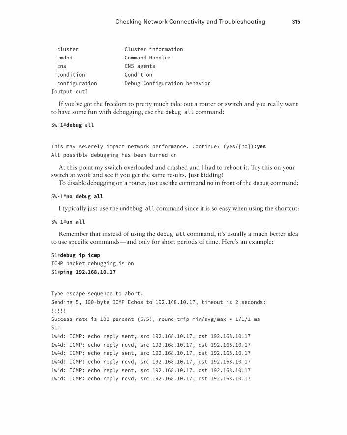
If you’ve got the freedom to pretty much take out a router or switch and you really want to have some fun with debugging, use the debug all command:
Sw-1#debug all
This may severely impact network performance. Continue? (yes/[no]):yesAll possible debugging has been turned on
At this point my switch overloaded and crashed and I had to reboot it. Try this on your switch at work and see if you get the same results. Just kidding!
To disable debugging on a router, just use the command no in front of the debug command:
SW-1#no debug all
I typically just use the undebug all command since it is so easy when using the shortcut:
SW-1#un all
Remember that instead of using the debug all command, it’s usually a much better idea to use specific commands—and only for short periods of time. Here’s an example:
S1#debug ip icmpICMP packet debugging is onS1#ping 192.168.10.17
Type escape sequence to abort.Sending 5, 100-byte ICMP Echos to 192.168.10.17, timeout is 2 seconds:!!!!!Success rate is 100 percent (5/5), round-trip min/avg/max = 1/1/1 msS1#1w4d: ICMP: echo reply sent, src 192.168.10.17, dst 192.168.10.171w4d: ICMP: echo reply rcvd, src 192.168.10.17, dst 192.168.10.171w4d: ICMP: echo reply sent, src 192.168.10.17, dst 192.168.10.171w4d: ICMP: echo reply rcvd, src 192.168.10.17, dst 192.168.10.171w4d: ICMP: echo reply sent, src 192.168.10.17, dst 192.168.10.171w4d: ICMP: echo reply rcvd, src 192.168.10.17, dst 192.168.10.17
316 Chapter 7 u Managing a Cisco Internetwork
1w4d: ICMP: echo reply sent, src 192.168.10.17, dst 192.168.10.171w4d: ICMP: echo reply rcvd, src 192.168.10.17, dst 192.168.10.171w4d: ICMP: echo reply sent, src 192.168.10.17, dst 192.168.10.171w4d: ICMP: echo reply rcvd, src 192.168.10.17, dst 192.168.10.17SW-1#un all
I’m sure you can see that the debug command is one powerful command. And because of this, I’m also sure you realize that before you use any of the debugging commands, you should make sure you check the CPU utilization capacity of your router. This is important because in most cases, you don’t want to negatively impact the device’s ability to process the packets on your internetwork. You can determine a specific router’s CPU utilization information by using the show processes command.
Remember, when you telnet into a remote device, you will not see console messages by default! For example, you will not see debugging output. To allow console messages to be sent to your Telnet session, use the terminal monitor command.
Using the show processes CommandAs I’ve said, you’ve really got to be careful when using the debug command on your devices. If your router’s CPU utilization is consistently at 50 percent or more, it’s probably not a good idea to type in the debug all command unless you want to see what a router looks like when it crashes!
So what other approaches can you use? Well, the show processes (or show processes cpu) is a good tool for determining a given router’s CPU utilization. Plus, it’ll give you a list of active processes along with their corresponding process ID, priority, scheduler test (status), CPU time used, number of times invoked, and so on. Lots of great stuff! Plus, this command is super handy when you want to evaluate your router’s performance and CPU utilization and are otherwise tempted to reach for the debug command!
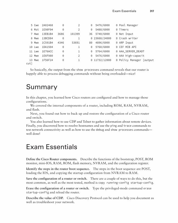
Okay—what do you see in the following output? The first line shows the CPU utilization output for the last 5 seconds, 1 minute, and 5 minutes. The output provides 5%/0% in front of the CPU utilization for the last 5 seconds: The first number equals the total utilization, and the second one indicates the utilization due to interrupt routines. Take a look:
SW-1#sh processesCPU utilization for five seconds: 5%/0%; one minute: 7%; five minutes: 8% PID QTy PC Runtime(ms) Invoked uSecs Stacks TTY Process 1 Cwe 29EBC58 0 22 0 5236/6000 0 Chunk Manager 2 Csp 1B9CF10 241 206881 1 2516/3000 0 Load Meter 3 Hwe 1F108D0 0 1 0 8768/9000 0 Connection Mgr 4 Lst 29FA5C4 9437909 454026 20787 5540/6000 0 Check heaps
Exam Essentials 317
5 Cwe 2A02468 0 2 0 5476/6000 0 Pool Manager 6 Mst 1E98F04 0 2 0 5488/6000 0 Timers 7 Hwe 13EB1B4 3686 101399 36 5740/6000 0 Net Input 8 Mwe 13BCD84 0 1 0 23668/24000 0 Crash writer 9 Mwe 1C591B4 4346 53691 80 4896/6000 0 ARP Input 10 Lwe 1DA1504 0 1 0 5760/6000 0 CEF MIB API 11 Lwe 1E76ACC 0 1 0 5764/6000 0 AAA_SERVER_DEADT 12 Mwe 1E6F980 0 2 0 5476/6000 0 AAA high-capacit 13 Mwe 1F56F24 0 1 0 11732/12000 0 Policy Manager [output cut]
So basically, the output from the show processes command reveals that our router is happily able to process debugging commands without being overloaded—nice!
SummaryIn this chapter, you learned how Cisco routers are configured and how to manage those configurations.
We covered the internal components of a router, including ROM, RAM, NVRAM, and flash.
Next, you found out how to back up and restore the configuration of a Cisco router and switch.
You also learned how to use CDP and Telnet to gather information about remote devices. Finally, you discovered how to resolve hostnames and use the ping and trace commands to test network connectivity as well as how to use the debug and show processes commands—well done!
Exam Essentials
Define the Cisco Router components. Describe the functions of the bootstrap, POST, ROM monitor, mini-IOS, RAM, ROM, flash memory, NVRAM, and the configuration register.
Identify the steps in the router boot sequence. The steps in the boot sequence are POST, loading the IOS, and copying the startup configuration from NVRAM to RAM.
Save the configuration of a router or switch. There are a couple of ways to do this, but the most common, as well as the most tested, method is copy running-config startup-config.
Erase the configuration of a router or switch. Type the privileged-mode command erase startup-config and reload the router.
Describe the value of CDP. Cisco Discovery Protocol can be used to help you document as well as troubleshoot your network.
318 Chapter 7 u Managing a Cisco Internetwork
List the information provided by the output of the show cdp neighbors command. The show cdp neighbors command provides the following information: device ID, local inter-face, holdtime, capability, platform, and port ID (remote interface).
Understand how to establish a Telnet session with multiple routers simultaneously. If you telnet to a router or switch, you can end the connection by typing exit at any time. However, if you want to keep your connection to a remote device but still come back to your original router console, you can press the Ctrl+Shift+6 key combination, release it, and then press X.
Identify current Telnet sessions. The command show sessions will provide you with infor-mation about all the currently active sessions your router has with other routers.
Build a static host table on a router. By using the global configuration command ip host host_name ip_address, you can build a static host table on your router. You can apply multiple IP addresses against the same host entry.
Verify the host table on a router. You can verify the host table with the show hosts command.
Describe the function of the ping command. Packet Internet Groper (ping) uses ICMP echo requests and ICMP echo replies to verify an active IP address on a network.
Ping a valid host ID from the correct prompt. You can ping an IP address from a router’s user mode or privileged mode but not from configuration mode, unless you use the do command. You must ping a valid address, such as 1.1.1.1.
Written Lab 7 319
Written Lab 7In this section, you’ll complete the following labs to make sure you’ve got the information and concepts contained within them fully dialed in:
Lab 7.1: IOS Management
Lab 7.2: Router Memory
The answers to these labs can be found in Appendix A, “Answers to Written Labs.”
Written Lab 7.1: IOS ManagementWrite the answers to the following questions:
1. What is the command to copy the startup-config file to DRAM?
2. What command can you use to see the neighbor router’s IP address from your router prompt?
3. What command can you use to see the hostname, local interface, platform, and remote port of a neighbor router?
4. What keystrokes can you use to telnet into multiple devices simultaneously?
5. What command will show you your active Telnet connections to neighbor and remote devices?
6. What command can you use to merge a backup configuration with the configuration in RAM?
7. What protocol can be used on a network to synchronize clock and date information?
8. What command is used by a router to forward a DHCP client request to a remote DHCP server?
9. What command enables your switch or router to receive clock and date information and synchronize with the NTP server?
10. Which NTP verification command will show the reference master for the client?
Written Lab 7.2: Router MemoryIdentify the location in a router where each of the following files is stored by default.
1. Cisco IOS
2. Bootstrap
3. Startup configuration
4. POST routine
5. Running configuration
320 Chapter 7 u Managing a Cisco Internetwork
6. ARP cache
7. Mini IOS
8. ROM Monitor
9. Routing tables
10. Packet buffers
Hands-on LabsTo complete the labs in this section, you need at least one router or switch (three would be best) and at least one PC running as a TFTP server. TFTP server software must be installed and running on the PC. For this lab, it is also assumed that your PC and the Cisco devices are connected together with a switch and that all interfaces (PC NIC and router interfaces) are in the same subnet. You can alternately connect the PC directly to the router or connect the routers directly to one another (use a crossover cable in that case). Remember that the labs listed here were created for use with real routers but can easily be used with LammleSim IOS Version or Cisco’s Packet Tracer program. Last, although it doesn’t matter if you are using a switch or router in these labs, I’m just going to use my routers, but feel free to use your switch to go through these labs!
Here is a list of the labs in this chapter:
Lab 7.1: Backing Up the Router Configuration
Lab 7.2: Using the Cisco Discovery Protocol (CDP)
Lab 7.3: Using Telnet
Lab 7.4: Resolving Hostnames
Hands-on Lab 7.1: Backing Up the Router ConfigurationIn this lab, you’ll back up the router configuration:
1. Log into your router and go into privileged mode by typing en or enable.
2. Ping the TFTP server to make sure you have IP connectivity.
3. From RouterB, type copy run tftp.
4. When prompted, type the IP address of the TFTP server (for example, 172.16.30.2) and press Enter.
5. By default, the router will prompt you for a filename. The hostname of the router is fol-lowed by the suffix -confg (yes, I spelled that correctly). You can use any name you want.
Name of configuration file to write [RouterB-confg]?
Hands-on Labs 321
Press Enter to accept the default name.
Write file RouterB-confg on host 172.16.30.2? [confirm]
Press Enter to confirm.
Hands-on Lab 7.2: Using the Cisco Discovery Protocol (CDP)CDP is an important objective for the Cisco exams. Please go through this lab and use CDP as much as possible during your studies.
1. Log into your router and go into privileged mode by typing en or enable.
2. From the router, type sh cdp and press Enter. You should see that CDP packets are being sent out to all active interfaces every 60 seconds and the holdtime is 180 seconds (these are the defaults).
3. To change the CDP update frequency to 90 seconds, type cdp timer 90 in global configuration mode.
Router#config tEnter configuration commands, one per line. End with CNTL/Z.Router(config)#cdp timer ? <5-900> Rate at which CDP packets are sent (in sec)Router(config)#cdp timer 90
4. Verify that your CDP timer frequency has changed by using the command show cdp in privileged mode.
Router#sh cdpGlobal CDP information:Sending CDP packets every 90 secondsSending a holdtime value of 180 seconds
5. Now use CDP to gather information about neighbor routers. You can get the list of available commands by typing sh cdp ?.
Router#sh cdp ? entry Information for specific neighbor entry interface CDP interface status and configuration neighbors CDP neighbor entries
322 Chapter 7 u Managing a Cisco Internetwork
traffic CDP statistics <cr>
6. Type sh cdp int to see the interface information plus the default encapsulation used by the interface. It also shows the CDP timer information.
7. Type sh cdp entry * to see complete CDP information received from all devices.
8. Type show cdp neighbors to gather information about all connected neighbors. (You should know the specific information output by this command.)
9. Type show cdp neighbors detail. Notice that it produces the same output as show cdp entry *.
Hands-on Lab 7.3: Using TelnetSecure Shell was covered in Chapter 6, which is what you should use for remote access into a Cisco device. However, the Cisco objectives cover telnet configuration, so let’s do a lab on telnet!
1. Log into your router and go into privileged mode by typing en or enable.
2. From RouterA, telnet into your remote router (RouterB) by typing telnet ip_address from the command prompt. Type exit to disconnect.
3. Now type in RouterB’s IP address from RouterA’s command prompt. Notice that the router automatically tries to telnet to the IP address you specified. You can use the telnet command or just type in the IP address.
4. From RouterB, press Ctrl+Shift+6 and then X to return to RouterA’s command prompt. Now telnet into your third router, RouterC. Press Ctrl+Shift+6 and then X to return to RouterA.
5. From RouterA, type show sessions. Notice your two sessions. You can press the number displayed to the left of the session and press Enter twice to return to that ses-sion. The asterisk shows the default session. You can press Enter twice to return to that session.
6. Go to the session for your RouterB. Type show users. This shows the console connec-tion and the remote connection. You can use the disconnect command to clear the session or just type exit from the prompt to close your session with RouterB.
7. Go to RouterC’s console port by typing show sessions on the first router and using the connection number to return to RouterC. Type show user and notice the connec-tion to your first router, RouterA.
8. Type clear line line_number to disconnect the Telnet session.
Hands-on Labs 323
Hands-on Lab 7.4: Resolving HostnamesIt’s best to use a DNS server for name resolution, but you can also create a local hosts table to resolve names. Let’s take a look.
1. Log into your router and go into privileged mode by typing en or enable.
2. From RouterA, type todd and press Enter at the command prompt. Notice the error you receive and the delay. The router is trying to resolve the hostname to an IP address by looking for a DNS server. You can turn this feature off by using the no ip domain-lookup command from global configuration mode.
3. To build a host table, you use the ip host command. From RouterA, add a host table entry for RouterB and RouterC by entering the following commands:
ip host routerb ip_addressip host routerc ip_address
Here is an example:
ip host routerb 172.16.20.2ip host routerc 172.16.40.2
4. Test your host table by typing ping routerb from the privileged mode prompt (not the config prompt).
RouterA#ping routerbType escape sequence to abort.Sending 5, 100-byte ICMP Echos to 172.16.20.2, timeout is 2 seconds:!!!!!Success rate is 100 percent (5/5), round-trip min/avg/max = 4/4/4 ms
5. Test your host table by typing ping routerc.
RouterA#ping routercType escape sequence to abort.Sending 5, 100-byte ICMP Echos to 172.16.40.2, timeout is 2 seconds:!!!!!Success rate is 100 percent (5/5), round-trip min/avg/max = 4/6/8 ms
324 Chapter 7 u Managing a Cisco Internetwork
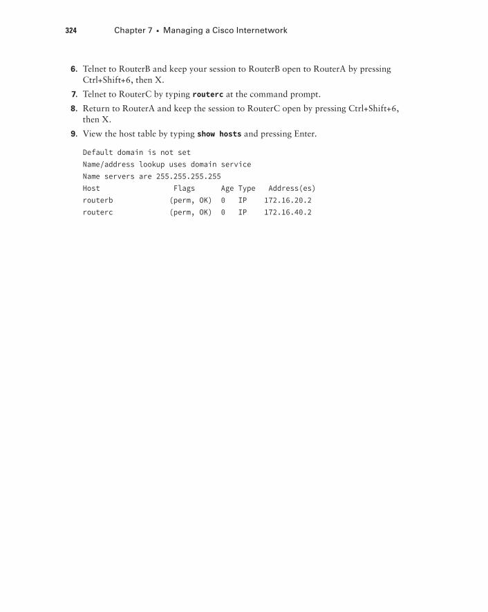
6. Telnet to RouterB and keep your session to RouterB open to RouterA by pressing Ctrl+Shift+6, then X.
7. Telnet to RouterC by typing routerc at the command prompt.
8. Return to RouterA and keep the session to RouterC open by pressing Ctrl+Shift+6, then X.
9. View the host table by typing show hosts and pressing Enter.
Default domain is not setName/address lookup uses domain serviceName servers are 255.255.255.255Host Flags Age Type Address(es)routerb (perm, OK) 0 IP 172.16.20.2routerc (perm, OK) 0 IP 172.16.40.2
Review Questions 325
Review Questions
The following questions are designed to test your understanding of this chapter’s material. For more information on how to get additional questions, please see this book’s introduction.
The answers to these questions can be found in Appendix B, “Answers to Chapter Review Questions.”
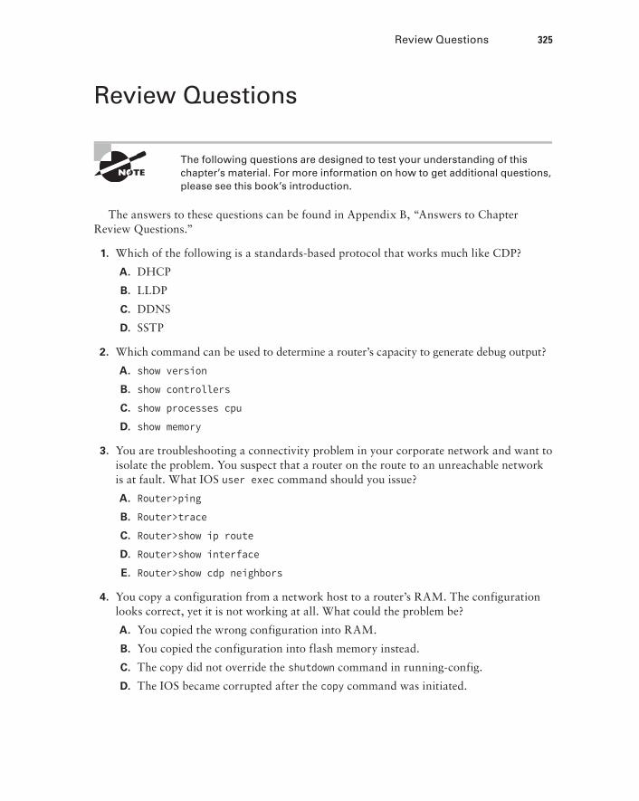
1. Which of the following is a standards-based protocol that works much like CDP?
A. DHCP
B. LLDP
C. DDNS
D. SSTP
2. Which command can be used to determine a router’s capacity to generate debug output?
A. show version
B. show controllers
C. show processes cpu
D. show memory
3. You are troubleshooting a connectivity problem in your corporate network and want to isolate the problem. You suspect that a router on the route to an unreachable network is at fault. What IOS user exec command should you issue?
A. Router>ping
B. Router>trace
C. Router>show ip route
D. Router>show interface
E. Router>show cdp neighbors
4. You copy a configuration from a network host to a router’s RAM. The configuration looks correct, yet it is not working at all. What could the problem be?
A. You copied the wrong configuration into RAM.
B. You copied the configuration into flash memory instead.
C. The copy did not override the shutdown command in running-config.
D. The IOS became corrupted after the copy command was initiated.
326 Chapter 7 u Managing a Cisco Internetwork
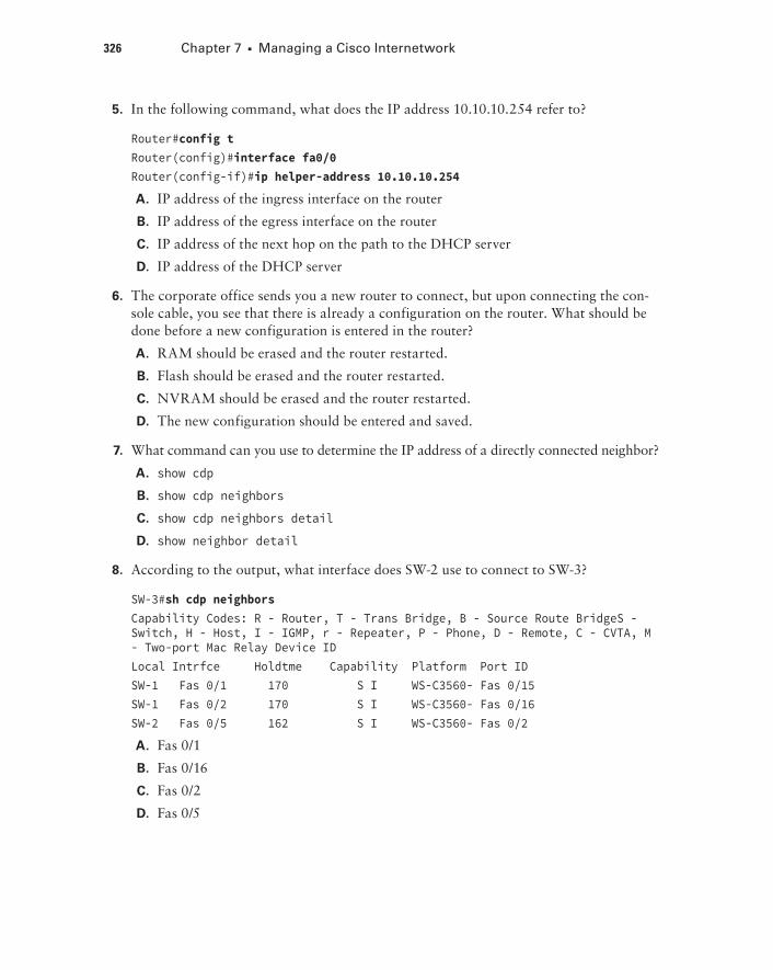
5. In the following command, what does the IP address 10.10.10.254 refer to?
Router#config tRouter(config)#interface fa0/0Router(config-if)#ip helper-address 10.10.10.254
A. IP address of the ingress interface on the router
B. IP address of the egress interface on the router
C. IP address of the next hop on the path to the DHCP server
D. IP address of the DHCP server
6. The corporate office sends you a new router to connect, but upon connecting the con-sole cable, you see that there is already a configuration on the router. What should be done before a new configuration is entered in the router?
A. RAM should be erased and the router restarted.
B. Flash should be erased and the router restarted.
C. NVRAM should be erased and the router restarted.
D. The new configuration should be entered and saved.
7. What command can you use to determine the IP address of a directly connected neighbor?
A. show cdp
B. show cdp neighbors
C. show cdp neighbors detail
D. show neighbor detail
8. According to the output, what interface does SW-2 use to connect to SW-3?
SW-3#sh cdp neighbors Capability Codes: R - Router, T - Trans Bridge, B - Source Route BridgeS - Switch, H - Host, I - IGMP, r - Repeater, P - Phone, D - Remote, C - CVTA, M - Two-port Mac Relay Device IDLocal Intrfce Holdtme Capability Platform Port IDSW-1 Fas 0/1 170 S I WS-C3560- Fas 0/15SW-1 Fas 0/2 170 S I WS-C3560- Fas 0/16SW-2 Fas 0/5 162 S I WS-C3560- Fas 0/2
A. Fas 0/1
B. Fas 0/16
C. Fas 0/2
D. Fas 0/5
Review Questions 327
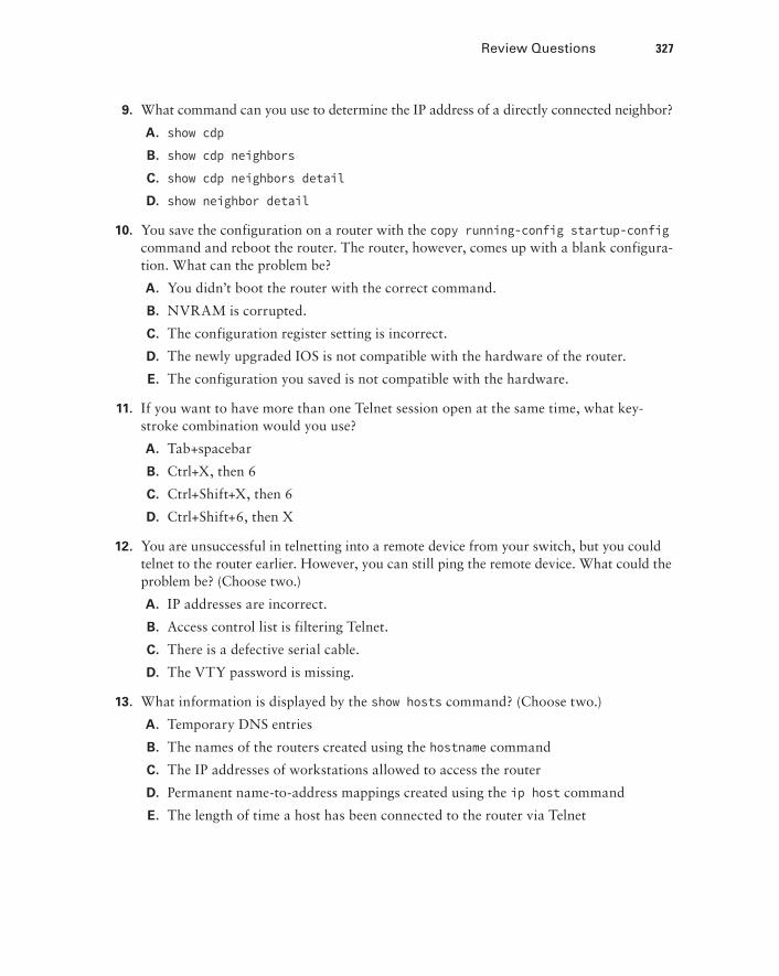
9. What command can you use to determine the IP address of a directly connected neighbor?
A. show cdp
B. show cdp neighbors
C. show cdp neighbors detail
D. show neighbor detail
10. You save the configuration on a router with the copy running-config startup-config command and reboot the router. The router, however, comes up with a blank configura-tion. What can the problem be?
A. You didn’t boot the router with the correct command.
B. NVRAM is corrupted.
C. The configuration register setting is incorrect.
D. The newly upgraded IOS is not compatible with the hardware of the router.
E. The configuration you saved is not compatible with the hardware.
11. If you want to have more than one Telnet session open at the same time, what key-stroke combination would you use?
A. Tab+spacebar
B. Ctrl+X, then 6
C. Ctrl+Shift+X, then 6
D. Ctrl+Shift+6, then X
12. You are unsuccessful in telnetting into a remote device from your switch, but you could telnet to the router earlier. However, you can still ping the remote device. What could the problem be? (Choose two.)
A. IP addresses are incorrect.
B. Access control list is filtering Telnet.
C. There is a defective serial cable.
D. The VTY password is missing.
13. What information is displayed by the show hosts command? (Choose two.)
A. Temporary DNS entries
B. The names of the routers created using the hostname command
C. The IP addresses of workstations allowed to access the router
D. Permanent name-to-address mappings created using the ip host command
E. The length of time a host has been connected to the router via Telnet
328 Chapter 7 u Managing a Cisco Internetwork
14. Which three commands can be used to check LAN connectivity problems on a switch? (Choose three.)
A. show interfaces
B. show ip route
C. tracert
D. ping
E. dns lookups
15. You telnet to a router and make your necessary changes; now you want to end the Telnet session. What command do you type in?
A. close
B. disable
C. disconnect
D. exit
16. You telnet into a remote device and type debug ip icmp, but no output from the debug command is seen. What could the problem be?
A. You must type the show ip icmp command first.
B. IP addressing on the network is incorrect.
C. You must use the terminal monitor command.
D. Debug output is sent only to the console.
17. You need to view console messages on a device to which you have connected through telnet. The command you need to execute to see these is ___________.
18. You need to gather the IP address of a remote switch that is located in Hawaii. What can you do to find the address?
A. Fly to Hawaii, console into the switch, then relax and have a drink with an umbrella in it.
B. Issue the show ip route command on the router connected to the switch.
C. Issue the show cdp neighbor command on the router connected to the switch.
D. Issue the show ip arp command on the router connected to the switch.
E. Issue the show cdp neighbors detail command on the router connected to the switch.
Review Questions 329
19. You need to configure all your routers and switches so they synchronize their clocks from one time source. What command will you type for each device?
A. clock synchronization ip_address
B. ntp master ip_address
C. sync ntp ip_address
D. ntp server ip_address version number
20. What two commands can you use to verify your NTP client?
A. show ntp server
B. show ntp status
C. show vtp status
D. show ntp associations
E. show clock source