Embed Size (px)
Citation preview

THE FORCE IS WITHIN

Carrier is a part of UTC Building & Industrial Systems, a unit of United Technologies
Corp.(UTC), a leading provider to the aerospace and building systems industries worldwide.
UTC was ranked at 151st position in Fortune 500 list of global corporations in 2014.
Built on Dr. Willis Carrier’s invention of modern air conditioning in 1902, Carrier’s research,
expertise and innovation have resulted in market leading solutions. We recognize the vital
importance of maintaining a responsible balance between the comfort we create today and the
world we live in tomorrow. Millions of people trust Carrier’s leadership in delivering efficient
solutions. To know more, please visit http://www.carrier.com.
Dr. Willis Carrier
Snapshots of Carrier India manufacturing facility
Over the years, Carrier India has significantly contributed in promoting sustainability. Carrier is the only
company in the world to be a founding member of the Green Building Councils of the U.S., Argentina,
China, India, Singapore and France. In fact, Carrier was instrumental in launching the U.S. Green
Building Council® (USGBC) in 1993 and was the first company in the world to join the organization.
It invests in R&D resources to advance energy efficiency, ozone layer protection and low global
warming technologies in its products. Carrier’s AdvanTE3C Solutions Center is a natural evolution
of Carrier's approach to sustainability and supports customers around the world in developing
strategic, energy-efficient and custom-engineered building solutions.
ACE(Achieving Competitive Excellence) is our proprietary operating system to ensure world-class
quality in our products and processes. With its relentless focus on increasing efficiency and reducing
waste, ACE is integral to the company's performance model.The company’s facilities worldwide are
using the operating system to improve quality and customer satisfaction while lowering cost.
Carrier’s presence in India dates back to 1986, when Carrier India was established. In the year 1988, the first
manufacturing facility was commissioned in Gurgaon, Haryana. Spread in an area of 19 acres, this state-of-the-art facility
consists of highly automated manufacturing unit, an excellent R&D Center and an advanced Quality Clinic. Currently,
products manufactured in this facility include Cassettes, Ducted Splits, Package Units, Air Cooled & Water Cooled Screw
Chillers, Air Cooled & Water Cooled Reciprocating Chillers, Fan Coil Units, Air Handling Units, Refrigeration products and
Fire & Security products.
Carrier’s efforts in promoting sustainability can be quantifiably measured by means of the Carrier
CO2NSERVATION Meter, which meticulously calculates the avoided greenhouse emissions with the help
of Carrier products, globally since 2000. To know more about the Carrier CO2NSERVATION Meter, please
visit http://www.naturalleader.com.
Carrier India
Our comprehensive Environment, Health & Safety (EH&S) program establishes a framework and provides tools for
implementing our EH&S practices into our business & culture. The Carrier Gurgaon facility holds a distinctive record of
delivering over 17 million man hours without a lost work day incident, clearly citing the measures of safety followed here.
Carrier India has 14 sales and service offices, more than 800 sales and service channel partners - throughout the country,
ensuring efficient solutions and quality services at customer’s doorstep. To know more visit http://www.carrierindia.com.

CARRIER STRENGTH:Progressing All Technologies SimultaneouslyThe main Carrier objective is to achieve the optimal balance between technological progress -
synonymous with performance - and environmental care - the guarantee for our future.
Carrier's strategy for the development of new products concentrates on three essential aspects:
- Minimising their impact on the environment
- Increasing their reliability and durability
- Raising the energy efficiency in response to latest regulations
The Aquaforce range is available in 22 models from 278 to 1518 kW and offers the best solution
for any individual projects and site requirements.

2
Environmentally sound
HFC-134a refrigerant
- Refrigerant of the HFC group with zero ozone depletion potential.
Leak-tight refrigerant circuit
- Reduction of leaks as no capillary tubes and flare connections are used.
- Verification of pressure transducers and temperature sensors without trans-
ferring refrigerant charge.
Absolute reliability
Easy and fast installation
Victaulic connections simplify the onsite installation
Simplified electrical connections
- Main disconnect switch with high trip capacity.
- Transformer to supply the integrated control circuit (400/24V).
Fast commissioning
- Factory charged refrigerant and oil
- Systematic factory operation test before shipment.
- Quick-test function for step-by-step verification of the instruments, expansion
devices, fans and compressors.
Screw compressors
- Industrial-type screw compressors with oversized bearings and motor cooled
by suction gas.
- All compressor components are easily accessible on site minimizing down-time.
- Electronic motor protection against overloads and power supply faults (loss
of phase, phase reversal).
Evaporator
- Thermal insulation with aluminium cladding (option) for perfect resistance
against outside aggression(mechanical and UV protection).
Exceptional endurance tests
- Partnerships with specialised laboratories and use of limit simulation tools
(finite element calculation) for the design of critical components.
- Transport simulation test in the laboratory on a vibrating table. The test is
based on a military standard and equivalent to 4000 km by truck.
- Salt mist corrosion resistance test in the laboratory for increased corrosion
resistance.
- Capable to operate at 55oC outdoor air temperature based on chilled water
temperature
Quiet operation
Compressors
- Discharge dampers integrated in the oil separator (Carrier patent).
- Acoustic compressor and oil separator enclosures (option) reduce the radiated noise.
Condenser section
- Condenser coils in V-shape with an open angle, allows quieter air flow across
the coil.
- Low-noise Flying Bird fans (Carrier patent) enjoy quieter operation and never
generate intrusive low-frequency noise.
- Rigid fan mounting prevents start-up noise (Carrier patent).
Economical operation
- Average Full Load COP of 3.2 at nominal conditions and average integrated
part load value (IPLV) of 4.4.
- New twin-rotor screw compressor equipped with a high efficiency motor and a va-
riable capacity valve that permits exact matching of the cooling capacity to the load.
- Flooded multi-pipe evaporator to increase the heat exchange efficiency, confi-
gured with aluminium cladding (option) to improve thermal insulation and
prevent energy loss.
- Electronic expansion device allows operation at a lower condensing pressure and
improved utilization of the evaporator heat exchange surface (superheat control).
- Economizer system with electronic expansion device permits a considerable
increase in cooling capacity and contributes to optimised energy efficiency of
the chiller installation.
Cooler aluminium protective cladding
(Optional)
New twin screw CARRIER compressor
Economizer system
a
Compressor ON
Compressor OFF
Adjustable control deadband
LWT
Set point
Made in state-of-the-art Carrier India facility
Safe operation
- Overload and lock rotor protection
- Reversal/ phase losing protection
- Protection of the compressor motor against high temperature
- High pressure switch for compressor protection
- Low current and short circuit protection
- High pressure safety valve installed on oil separator
Safety valve on the evaporator shell
- Flow switch installed on the water box
Features and Benefits
Patented Flying Bird IV axial flow low noise fan

3
Environmentally sound
HFC-134a refrigerant
- Refrigerant of the HFC group with zero ozone depletion potential.
Leak-tight refrigerant circuit
- Reduction of leaks as no capillary tubes and flare connections are used.
- Verification of pressure transducers and temperature sensors without trans-
ferring refrigerant charge.
Absolute reliability
Easy and fast installation
Victaulic connections simplify the onsite installation
Simplified electrical connections
- Main disconnect switch with high trip capacity.
- Transformer to supply the integrated control circuit (400/24V).
Fast commissioning
- Factory charged refrigerant and oil
- Systematic factory operation test before shipment.
- Quick-test function for step-by-step verification of the instruments, expansion
devices, fans and compressors.
Screw compressors
- Industrial-type screw compressors with oversized bearings and motor cooled
by suction gas.
- All compressor components are easily accessible on site minimizing down-time.
- Electronic motor protection against overloads and power supply faults (loss
of phase, phase reversal).
Evaporator
- Thermal insulation with aluminium cladding (option) for perfect resistance
against outside aggression(mechanical and UV protection).
Exceptional endurance tests
- Partnerships with specialised laboratories and use of limit simulation tools
(finite element calculation) for the design of critical components.
- Transport simulation test in the laboratory on a vibrating table. The test is
based on a military standard and equivalent to 4000 km by truck.
- Salt mist corrosion resistance test in the laboratory for increased corrosion
resistance.
- Capable to operate at 55oC outdoor air temperature based on chilled water
temperature
Quiet operation
Compressors
- Discharge dampers integrated in the oil separator (Carrier patent).
- Acoustic compressor and oil separator enclosures (option) reduce the radiated noise.
Condenser section
- Condenser coils in V-shape with an open angle, allows quieter air flow across
the coil.
- Low-noise Flying Bird fans (Carrier patent) enjoy quieter operation and never
generate intrusive low-frequency noise.
- Rigid fan mounting prevents start-up noise (Carrier patent).
Economical operation
- Average Full Load COP of 3.2 at nominal conditions and average integrated
part load value (IPLV) of 4.4.
- New twin-rotor screw compressor equipped with a high efficiency motor and a va-
riable capacity valve that permits exact matching of the cooling capacity to the load.
- Flooded multi-pipe evaporator to increase the heat exchange efficiency, confi-
gured with aluminium cladding (option) to improve thermal insulation and
prevent energy loss.
- Electronic expansion device allows operation at a lower condensing pressure and
improved utilization of the evaporator heat exchange surface (superheat control).
- Economizer system with electronic expansion device permits a considerable
increase in cooling capacity and contributes to optimised energy efficiency of
the chiller installation.
Cooler aluminium protective cladding
(Optional)
New twin screw CARRIER compressor
Economizer system
a
Compressor ON
Compressor OFF
Adjustable control deadband
LWT
Set point
Made in state-of-the-art Carrier India facility
Safe operation
- Overload and lock rotor protection
- Reversal/ phase losing protection
- Protection of the compressor motor against high temperature
- High pressure switch for compressor protection
- Low current and short circuit protection
- High pressure safety valve installed on oil separator
Safety valve on the evaporator shell
- Flow switch installed on the water box
Features and Benefits
Patented Flying Bird IV axial flow low noise fan

4
Pro-Dialog Plus Control
Pro-Dialog Plus combines advanced control logic with simple operation. The control system monitors all operation parameters all the time and precisely manages the operation of compressors, electronic expansion devices, fans for optimized energy efficiency.
User-friendly interface- The new backlighted LCD interface includes a manual control potentiometer to ensure legibility under any lighting conditions. The information is in clear text and can be displayed in English.- Unit uses intuitive tree-structure menus, similar to the internet navigators. They are user-friendly and permit quick access to the principal operating parameters: number of compressors operating, suction/discharge pressure, compressor operating hours, set point, air temperature, entering/leaving water temperature.- Large touch screen user interface offers intuitive access to the operating parameters. The information is in clear text and can be displayed in English.
Advanced control function- Unit provides different control mode including LOCAL/REMOTE/CCN.- Remote control function including: Unit ON/OFF, dual set point control, 2-level demand limit control, user safety interlock, water pump operation control, operation indication, circuit alarm and alert etc.- Automatic reset of leaving water temperature based on return water temperature or outside air temperature to ensure optimized energy efficiency.- Control algorithm prevents excessive compressor cycling and permits reduction of the water quantity in the hydronic circuit (Carrier patent).- Automatic compressor unloading in case of abnormally high condensing pressure. If an abnomal incident occurs (e.g. fouled condenser coil, fan failure), Aquaforce continues to operate, but at reduced capacity.
Powerful Diagnostics- A quick test of all unit components and control points to verify the correct operation of every switch, circuit breaker, contactor etc. at the start of the chiller.- Real-time monitoring of all the operation parameters, and alarm when necessary.- Control system is facilitated with RS485 serial communication port for remote diagnosis or special diagnostic tools.
Sufficient safety measures- Password protection in case of mishandling.- Unit is protected against: Loss of refrigerant charge, reverse rotation, low chilled water temperature, low oil pressure (per compressor), current imbalance, compressor thermal overload, excessive air temperature, high pressure, electrical overload, loss of phase.
Group control- Master/slave control of two chillers connected to automatically balance operating times, and also automatically conduct change-over in case of a unit fault.- Communication with other Building Management System (BMS) by selecting BacNet/J-Bus/LonTalk gateway.
Pro-Dialog Plus interface Pro-Dialog Plus with touch screen

5
No.
002B
003A
005
015
020A
Advantages
Improved corrosion resistance, recommended for heavy marine and
industrial environments
Improved corrosion resistance, recommended for light marine
environments
For low temperature applications such as ice storage, cold stores or process
cooling etc.
Low operating noise
Improved electrical box protection, recommended for dusty / sandy
environments
Evaporator Water Pressure Drop
10
20 30 40 50 60 70 80 90 100
20
30
40
50
60
70
80
90
100
01
Water flow rate l/s
Wate
r pre
ssure
dro
p, kP
a
②
① 652/712/762②③
③
1052/1152/1252
1312/1392
1
23
Options & accessoriesOptions
Blygold PoluAL
Gold Fin
Medium brine*
Low noise
IP54
Description
Coil with factory-appliedBlygold PoluAL treatment
Fin made of pre-treatedaluminium (polyurethane
and epoxy)
Leaving water temperature downto -6 °C
Compressor sound enclosure
IP 54 electrical box protection
10
20
30
40
50
60
70
80
90
100
10 20 30 40 50 60 70 80 90 100
0702
0752
0852
0902
1002
1352
1502
Water flow rate, l/s
Pre
ssure
dro
p,
kP
a
1
1
2
3
4
5
6
7
2 3 764 5
10
20
30
40
50
60
70
80
90
100
10 20 30 40 50
0282/0342
0452
0442/0482
0502
Water flow rate, l/s
Pre
ssure
dro
p,
kP
a
1
2
3
4
5 0602
1 2 3
4 5
* Available with select models–30XA0452/0502/0602/0702/0752/0852/0902/1002/1352/1502

6
Technical Specifications
Unit with Cu/Al condenser coil
* Nominal conditions - evaporator entering/leaving water temperature 12/7oC, outdoor air temperature 35oC; Evaporator fouling factor 0.018m2K/kW
30XA 0282 0342 0442 0452 0482 0502 0602 0652 0702 0712 0752
nominal cooling capacity* kW 278 328 444 452 493 503 619 644 674 697 729
Compressor input power kW 78.8 90.5 133.7 129.8 143.3 141.3 175.3 190.4 188.8 205 213.5
Fan and control power kW 8.4 9.8 11.8 11.8 14.6 14.0 16.8 15.6 19.0 16.9 20.2
COP 3.19 3.27 3.05 3.19 3.12 3.24 3.22 3.13 3.24 3.15 3.12
Refrigerant HFC-134a
Circuit A kg 97 102 113 85 119 102 102 180 100 185 129
Circuit B kg - - - 56 - 56 88 - 95 - 88
Circuit C kg - - - - - - - - - - -
Compressor Semi-hermetic screw compressor
Circuit A 1 1 1 1 1 1 1 1 1 1 1
Circuit B - - - 1 - 1 1 - 1 - 1
Circuit C - - - - - - - - - - -
Minimum capacity % 30 30 30 15 30 15 15 30 15 30 15
Control Pro-Dialog Plus, electronic expansion valve (EXV)
Condenser Cu/Al heat exchanger
Fans Axial Flying Bird with rotating shround
Quantity 5 6 7 8 8 9 11 10 12 11 13
Total air flow m3/s 22.6 27.1 31.6 36.1 36.1 40.6 49.7 45.1 54.2 49.7 58.7
Fan speed rpm 950 950 950 950 950 950 950 950 950 950 950
Evaporator Flooded multi-pipe
Water content l 49 54 76 70 77 77 79 78 94 78 99
Nominal water flow l/s 13.3 15.6 21.2 21.5 23.5 24.0 29.5 31 32.1 33 34.8
Nominal water pressure drop kPa 22 29 34 38 41 36 46 33 37 43 38
Max. water-side pressure without hydronic module kPa 1000 1000 1000 1000 1000 1000 1000 1000 1000 1000 1000
Water connection Victaulic
Nominal Diameter DN 125 125 125 125 125 125 125 150 150 150 150
Electrical data
Nominal power supply 400V-3Ph-50Hz
Start-up method Star-delta start
Control power supply 24V via internal transformer
Nominal unit current drawCircuit A+B A 147 173 262 238 273 264 320 336 346 363 404
Circuit C A - - - - - - - - - - -
Maximum unit current drawCircuit A+B A 180 229 314 316 367 350 423 415 457 452 512
Circuit C A - - - - - - - - - - -
Maximum start-up currentCircuit A+B A 275 308 504 510 587 510 583 629 616 629 782
Circuit C A - - - - - - - - - - -
Unit length m 3.6 3.6 4.8 4.8 4.8 6.0 7.2 6.0 7.2 7.2 8.4
Unit width m 2.3 22.3 2.3 2.3 2.3 2.3 2.3 2.3 2.3 2.3 2.3
Unit height m 2.3 22.3 2.3 2.3 2.3 2.3 2.3 2.3 2.3 2.3 2.3
Unit weight kg 3523 3820 4571 4823 4900 5393 6392 5250 6544 5916 7331
Operating weight kg 3578 3875 4641 4900 4984 5470 6480 5328 6640 5994 7430

7
Technical Specifications
30XA 0762 0852 0902 1002 1052 1152 1252 1312 1392 1352 1502
Nominal cooling capacity* kW 737 833 906 988 1089 1134 1254 1325 1382 1449 1518
Compressor input power kW 215.4 238.8 261.4 288.2 318 332 373 395 415 435.4 436.8
Fan and control power kW 18.2 23.0 24.9 26.7 27.4 29.1 30.4 31.2 31.2 30.8 40.3
COP 3.16 3.18 3.16 3.14 3.16 3.15 3.11 3.11 3.10 3.11 3.18
Refrigerant HFC-134a
Circuit A kg 195 130 129 140 180 180 190 185 185 112 140
Circuit B kg – 95 103 129 110 114 114 180 185 98 129
Circuit C kg – – - - - - - - - 117 130
Compressor Semi-hermetic screw compressor
Circuit A 1 1 1 1 1 1 1 1 1 1 1
Circuit B – 1 1 1 1 1 1 1 1 1 1
Circuit C – – - - - - - - - 1 1
Minimum capacity % 30 15 15 15 15 15 15 15 15 10 10
Control Pro-Dialog Plus, electronic expansion valve (EXV)
Condenser Cu/Al heat exchanger
Fans Axial Flying Bird with rotating shround
Quantity 12 14 15 16 17 18 19 20 20 20 24
Total air flow m3/s 54.2 63.2 67.7 72.2 76.7 81.3 85.8 90.3 90.3 90.3 108.3
Fan speed rpm 950 950 950 950 950 950 950 950 950 950 950
Evaporator Flooded multi-pipe
Water content l 78 119 130 140 144 144 144 156 156 224 240
Nominal water flow l/s 35 39.7 43.2 47.1 52 54 60 63 66 69.1 72.4
Nominal water pressure drop kPa 51.4 39 38 36 41 45 57 53 60 45 48
Max. water-side pressure without hydronic module kPa 1000 1000 1000 1000 1000 1000 1000 1000 1000 1000 1000
Water connection Victaulic
Nominal Diameter DN 150 150 150 200 150 150 150 150 150 200/150 200/150
Electrical data
Nominal power supply 400V-3Ph-50Hz
Start-up method Star-delta start
Control power supply 24V via internal transformer
Nominal unit current drawCircuit A+B A 383 446 516 546 568 590 658 697 730 537 546
Circuit C A – – - - - - - - - 275 273
Maximum unit current drawCircuit A+B A 479 596 635 734 722 769 830 864 884 678 734
Circuit C A – – - - - - - - - 364 367
Maximum start-up currentCircuit A+B A 629 815 905 954 1044 1044 1111 1122 1122 901 954
Circuit C A – – - - - - - - - 587 587
Unit length m 7.2 8.4 9.6 9.6 10.8 10.8 12.0 12.0 12.0 12.0 14.4
Unit width m 2.3 2.3 2.3 2.3 2.3 2.3 2.3 2.3 2.3 2.3 2.3
Unit height m 2.3 2.3 2.3 2.3 2.3 2.3 2.3 2.3 2.3 2.3 2.3
Unit weight kg 6002 7749 8487 8723 9108 9188 9723 10344 10344 11831 13156
Operating weight kg 6080 7870 8620 8870 9252 9332 9867 10500 10500 12060 13400
* Nominal conditions - evaporator entering/leaving water temperature 12/7oC, outdoor air temperature 35oC Evaporator fouling factor 0.018m2K/kW
Unit with Cu/Al condenser coil
8
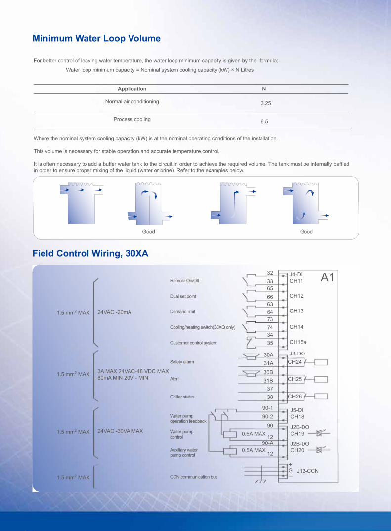
Remote On/Off
Dual set point
Demand limit
Cooling/heating switch(30XQ only)
Customer control system
Safety alarm
Alert
Chiller status
Water pump
Water pump
Auxiliary water
CCN communication bus
operation feedback
pump control
control
For better control of leaving water temperature, the water loop minimum capacity is given by the formula:
Water loop minimum capacity = Nominal system cooling capacity (kW) × N Litres
Normal air conditioning
N
Bad Bad
3.25
Field Control Wiring, 30XA
Minimum Water Loop Volume
Application
Process cooling
Where the nominal system cooling capacity (kW) is at the nominal operating conditions of the installation.
This volume is necessary for stable operation and accurate temperature control.
It is often necessary to add a buffer water tank to the circuit in order to achieve the required volume. The tank must be internally baffled in order to ensure proper mixing of the liquid (water or brine). Refer to the examples below.
Good Good
6.5

9
Operating Range, 30XA
Note: A glycol/water solution or evaporator anti-freeze protection must be used if the air temperature is below 0°C or leaving water temperature is below 4oC.* Max 55°C during part load operation, based on chilled water temperature.
Cooling mode
Evaporator Min.temperature Max.temperature
Entering water temperature (at start) - 45˚C
Entering water temperature (during operation) 6.8˚C 21˚C
Leaving water temperature (during operation) 3.3˚C 15˚C
Condenser Min.temperature Max.temperature
Outdoor air temperature -10˚C 55˚C*

1800 3000 3545
For more details, please contact our Carrier India sales office: Factory & Corporate Office: Carrier Airconditioning & Refrigeration Ltd, Kherki Daula Post, Narsingpur, Gurgaon 122004, Tel: 0124-4825500Sales Offices:– Delhi/NCR: 0124–2706000 Ghaziabad: 0120-4183260 Lucknow: 0522-4158703/4158710 Chandigarh: 0172-5007549/ 5007550 Jaipur: 0141-4109080 Indore: 0731-4070378 Mumbai: 022-61700700 Ahmedabad: 079-44820400 Pune: 020-67045100 Kolkata: 033-40524354 Chennai: 044-66448888 Bangalore: 080-43442000 Hyderabad: 040-41100222 Cochin: 0484-4029001/0
CIN: U74999HR1992FLC036104/ Website: www.carrierindia.com/ E-mail: [email protected]
This catalogue provides certain general information and is intended for general guidance only and Carrier is not liable for any damage arising out of the use of the catalogueThe Manufacturer reserves the right to change any product specification without prior notice