Embed Size (px)
Citation preview
40
The goals of these developmental efforts were (and still are) to improve efficiency and maximize electrical power output while minimizing power system weight, all the while striving for the highest level of safety.
41Photo Credit
Advanced Isotope Power Systems Expanding RPS Boundaries3A
s RTG technology continued its evolution through the 1970s and 1980s, development of advanced isotope power systems remained an important goal within DOE and NASA. �e goals of these developmental efforts were (and still are) to improve
efficiency while minimizing power system mass, all the while striving for the highest level of safety. With these goals in mind, the agencies sought to take advantage of advancements in materials, power conversion technolo-gies, and fabrication and production techniques. In so doing, their efforts served to expand the knowledge base of RPS technology and provided a platform from which future development efforts might build.
A Modular RTG
�roughout the 1980s, development and production of the new GPHS-RTG for the Galileo and Ulysses missions were the primary focus for DOE. With its modular heat source and improved power conversion system, the GPHS-RTG was a marked improvement over the MHW and SNAP-19 RTGs, especially in terms of specific power. Soon, however, RTG visionaries began to evaluate the viability of a variation of the design that would bring modularity to the converter level as well as the heat source level.
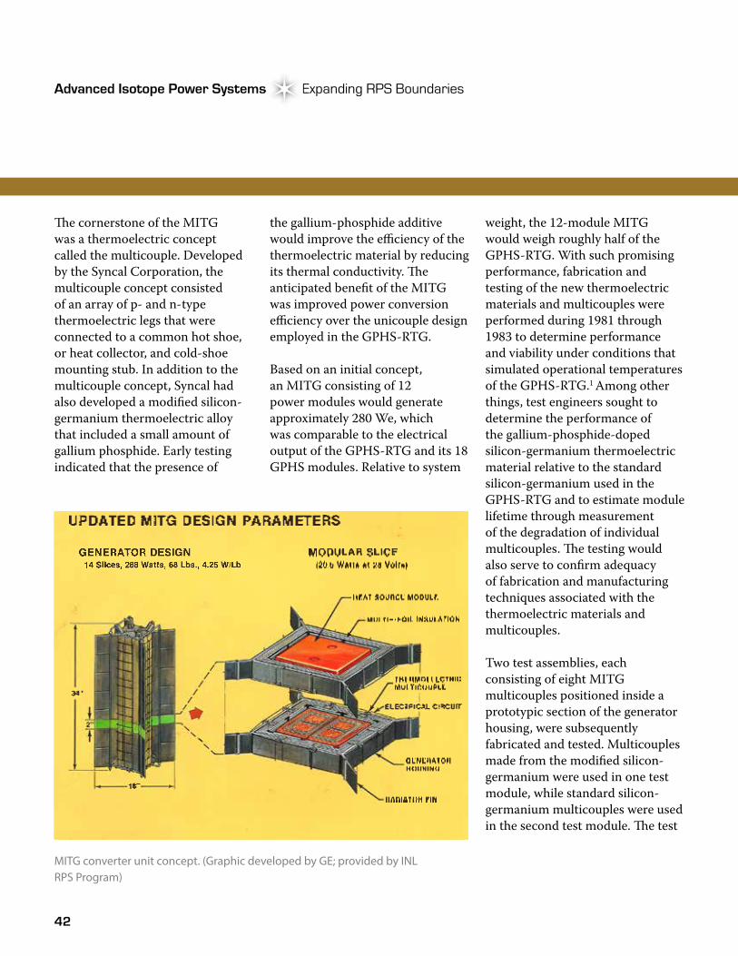
In 1980, DOE contracted with Fairchild Space and Electronics Company to develop and analyze a new RTG design based on advanced materials and fabrication techniques, as well as the new GPHS that was under development by LANL, Fairchild, and GE. �e RTG concept subsequently developed by Fairchild was called the modular isotopic thermoelectric generator (MITG). As conceived, the MITG concept included a single GPHS module surrounded axially by eight multicouples, as well as a standardized section of thermal insulation, housing, radiator fins, and electrical circuit. With a projected electrical power output of approximately 20 watts, individual MITG units could be combined to create an RTG that would be scalable over a range of power levels. Power-level increments of less than 20 watts would be accommodated by adjusting the size of the heat rejection fins located on the outside of the generator housing.1
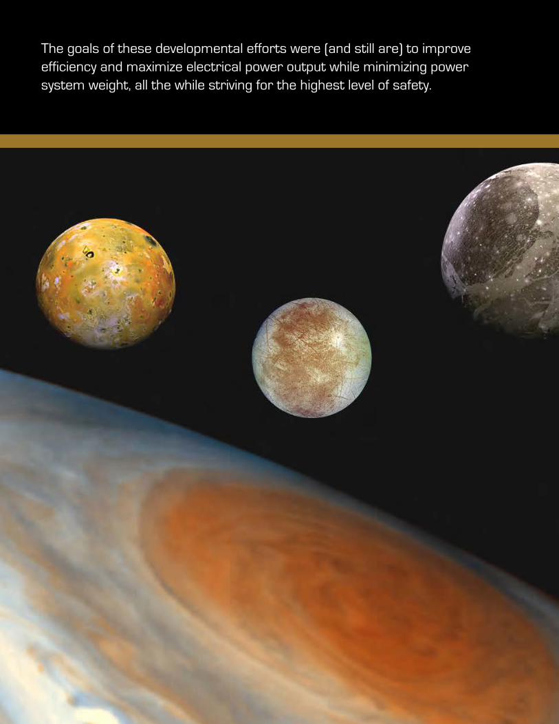
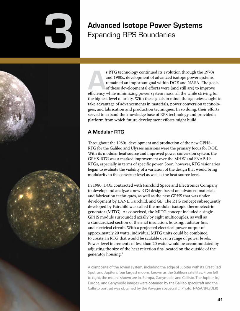
A composite of the Jovian system, including the edge of Jupiter with its Great Red Spot, and Jupiter’s four largest moons, known as the Galilean satellites. From left to right, the moons shown are Io, Europa, Ganymede, and Callisto. The Jupiter, Io, Europa, and Ganymede images were obtained by the Galileo spacecraft and the Callisto portrait was obtained by the Voyager spacecraft. (Photo: NASA/JPL/DLR)
42
Advanced Isotope Power Systems Expanding RPS BoundariesAdvanced Isotope Power Systems
�e cornerstone of the MITG was a thermoelectric concept called the multicouple. Developed by the Syncal Corporation, the multicouple concept consisted of an array of p- and n-type thermoelectric legs that were connected to a common hot shoe, or heat collector, and cold-shoe mounting stub. In addition to the multicouple concept, Syncal had also developed a modified silicon-germanium thermoelectric alloy that included a small amount of gallium phosphide. Early testing indicated that the presence of
the gallium-phosphide additive would improve the efficiency of the thermoelectric material by reducing its thermal conductivity. �e anticipated benefit of the MITG was improved power conversion efficiency over the unicouple design employed in the GPHS-RTG.
Based on an initial concept, an MITG consisting of 12 power modules would generate approximately 280 We, which was comparable to the electrical output of the GPHS-RTG and its 18 GPHS modules. Relative to system
weight, the 12-module MITG would weigh roughly half of the GPHS-RTG. With such promising performance, fabrication and testing of the new thermoelectric materials and multicouples were performed during 1981 through 1983 to determine performance and viability under conditions that simulated operational temperatures of the GPHS-RTG.1 Among other things, test engineers sought to determine the performance of the gallium-phosphide-doped silicon-germanium thermoelectric material relative to the standard silicon-germanium used in the GPHS-RTG and to estimate module lifetime through measurement of the degradation of individual multicouples. �e testing would also serve to confirm adequacy of fabrication and manufacturing techniques associated with the thermoelectric materials and multicouples.
Two test assemblies, each consisting of eight MITG multicouples positioned inside a prototypic section of the generator housing, were subsequently fabricated and tested. Multicouples made from the modified silicon-germanium were used in one test module, while standard silicon-germanium multicouples were used in the second test module. �e test
MITG converter unit concept. (Graphic developed by GE; provided by INL RPS Program)
43
Atomic Power in Space II Chapter 3Atomic Power in Space II Chapter 3
assemblies were heated electrically using a heater that was enclosed in an insulated graphite box having the same outer dimensions as a GPHS module.
�e tests served their purpose, as a number of issues were subsequently identified. For example, crack formation was observed in the multicouples. Subsequent investigation revealed the cause of the cracking to be thermal stresses occurring at the joints of the thermocouple array and the hot and cold shoes. �e multicouple was subsequently redesigned to incorporate stress-relief features at the problem areas.2, 3 In addition to the stress-cracking problem, independent testing of the gallium-phosphide-doped silicon-germanium thermoelectric material, performed at DOE’s request, revealed material efficiencies that were lower than those previously reported (although they were higher than those of the standard silicon germanium alloy). Lessons learned from the testing were incorporated into a revised MITG design as well as fabrication and manufacturing processes. With improvements underway, DOE decided to test the MITG technology in a ground demonstration system as part of a follow-on modular (MOD) RTG development program (MOD-RTG). �e MITG program ended in September 1983.4
MOD-RTG
Managed for DOE by GE, the goal of the MOD-RTG program was to develop a ground demonstration system to test the modular RTG concept. Beginning in October 1983, a three-year plan was developed to fabricate and test an electrically heated MOD-RTG demonstration unit based on six GPHS converter units.5 By mid-1985, GE (with the help of Fairchild) had completed a reference flight design and a ground demonstration system design. With a single thermoelectric multicouple device designed to produce 19 We from one GPHS module, the reference design consisted of 18 GPHS modules and 144 thermoelectric multicouples to produce 340 We.6 With a projected specific power of approximately 7.9 We/kilogram (based on a weight of approximately 42 kilograms [92 pounds]), the MOD-RTG reference flight design was significantly higher than the 5.4 We/kilogram GPHS-RTG. Fabrication of a ground demonstration system began in the summer of 1985.
Although initially optimistic, the MOD-RTG project soon found itself facing problems similar to the MITG effort. Multicouple testing revealed continued performance issues, including mechanical and electrical shorting problems, material issues associated with
the gallium phosphide, and thermoelectric degradation faster than expected. In its attempt to address the thermoelectric issues, DOE suspended fabrication of the ground demonstration system in mid-1986. Efforts to address the multicouple performance issues stretched into a multi-year task and were the primary focus of project efforts through 1992 when the project was finally terminated. In spite of the difficulties encountered and technical challenges that remained at the time of project termination, the nine-year MOD-RTG effort did see some significant accomplishments, including the development of reproducible manufacturing processes for multicouple fabrication, resolution of mechanical and electrical-shorting problems that had been identified early in the project, and an understanding of the degradation mechanisms associated with the multicouples. Although follow-on work was recommended, DOE priorities shifted to production of the GPHS-RTGs for the Cassini mission slated for flight in 1997.7
44
Advanced Isotope Power Systems Expanding RPS BoundariesAdvanced Isotope Power Systems
Taking Energy From Heat
Thermodynamic cycles are the basis for many common technologies, including refrigeration, car engines, and aircraft jet engines. A thermodynamic cycle is a process that manipulates the temperature, pressure, and volume of a working �uid to either convert heat into energy or use energy to remove heat. Each cycle has its own intricacies but shares four common processes: compression, heat addition, expansion, and heat removal (cooling). Three thermodynamic cycles are of key interest to the space program due to their high e�ciency and compatibility with various energy sources (e.g., solar and nuclear).
Rankine—Often used in steam power plants where water is boiled to produce superheated steam, which is expanded through a turbine to produce electricity; the steam is condensed back into water and pumped to the boiler to restart the cycle. For space applications, di�erent working �uids (e.g., mercury, potassium, toluene) are considered based on design criteria that include weight and system operating temperatures and pressures. The fact that Rankine uses a two-phase (liquid and gas) operation creates engineering challenges that must be addressed in the low and zero gravity of space. However, because phase changes are an e�cient way to transfer heat, Rankine cycles are typically the lowest mass option for high-power space applications.
Brayton—Jet engines and power-producing gas turbines often use this cycle. A working gas is compressed, heated to increase its pressure, and expanded through a turbine to produce electricity. The turbine is attached to the compressor to power the pressurization step. In a jet engine, the hot air is rejected to the atmosphere and fresh air is taken in. In a power plant, the waste heat can be used in a boiler to create steam for use in a Rankine cycle; such use is referred to as a combined cycle. Brayton engines in space must use a closed system and recycle their working gas (typically helium and/or xenon), which must be cooled before re-entering the compressor.
Stirling—As with other cycles, the working gas is compressed, heat is added, the gas is expanded, and heat is removed to restart the process. A variety of Stirling-engine types exist. The ones most recently investigated for potential space use are known as free-piston Stirling engines. In this con�guration, the engine is a cylinder with one end exposed to a heat source and the other kept at a lower temperature using a heat exchanger. A displacer piston inside the cylinder moves gas between hot and cold spaces and is thermodynamically coupled to a power piston. The pressure changes caused by the addition and removal of heat at the two ends of the cylinder cause the two pistons to oscillate. The power piston can be used to drive a linear alternator to generate electricity from this motion. For the small Stirling engines that have been most recently developed for potential RPS use, these oscillations are extremely fast, on the order of 50 to 100 cycles per second, and with a piston stroke of just a few millimeters.
45
Atomic Power in Space II Chapter 3Atomic Power in Space II Chapter 3
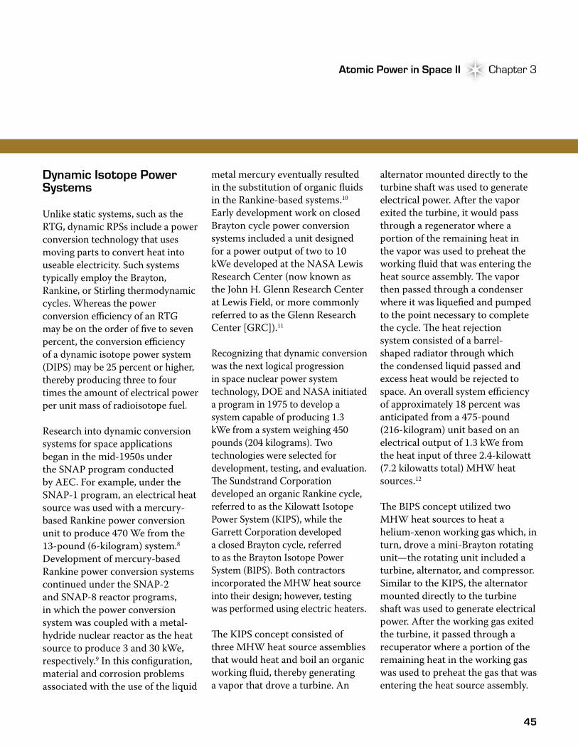
Dynamic Isotope Power Systems
Unlike static systems, such as the RTG, dynamic RPSs include a power conversion technology that uses moving parts to convert heat into useable electricity. Such systems typically employ the Brayton, Rankine, or Stirling thermodynamic cycles. Whereas the power conversion efficiency of an RTG may be on the order of five to seven percent, the conversion efficiency of a dynamic isotope power system (DIPS) may be 25 percent or higher, thereby producing three to four times the amount of electrical power per unit mass of radioisotope fuel.
Research into dynamic conversion systems for space applications began in the mid-1950s under the SNAP program conducted by AEC. For example, under the SNAP-1 program, an electrical heat source was used with a mercury-based Rankine power conversion unit to produce 470 We from the 13-pound (6-kilogram) system.8 Development of mercury-based Rankine power conversion systems continued under the SNAP-2 and SNAP-8 reactor programs, in which the power conversion system was coupled with a metal-hydride nuclear reactor as the heat source to produce 3 and 30 kWe, respectively.9 In this configuration, material and corrosion problems associated with the use of the liquid
metal mercury eventually resulted in the substitution of organic fluids in the Rankine-based systems.10 Early development work on closed Brayton cycle power conversion systems included a unit designed for a power output of two to 10 kWe developed at the NASA Lewis Research Center (now known as the John H. Glenn Research Center at Lewis Field, or more commonly referred to as the Glenn Research Center [GRC]).11
Recognizing that dynamic conversion was the next logical progression in space nuclear power system technology, DOE and NASA initiated a program in 1975 to develop a system capable of producing 1.3 kWe from a system weighing 450 pounds (204 kilograms). Two technologies were selected for development, testing, and evaluation. �e Sundstrand Corporation developed an organic Rankine cycle, referred to as the Kilowatt Isotope Power System (KIPS), while the Garrett Corporation developed a closed Brayton cycle, referred to as the Brayton Isotope Power System (BIPS). Both contractors incorporated the MHW heat source into their design; however, testing was performed using electric heaters.
�e KIPS concept consisted of three MHW heat source assemblies that would heat and boil an organic working fluid, thereby generating a vapor that drove a turbine. An
alternator mounted directly to the turbine shaft was used to generate electrical power. After the vapor exited the turbine, it would pass through a regenerator where a portion of the remaining heat in the vapor was used to preheat the working fluid that was entering the heat source assembly. �e vapor then passed through a condenser where it was liquefied and pumped to the point necessary to complete the cycle. �e heat rejection system consisted of a barrel-shaped radiator through which the condensed liquid passed and excess heat would be rejected to space. An overall system efficiency of approximately 18 percent was anticipated from a 475-pound (216-kilogram) unit based on an electrical output of 1.3 kWe from the heat input of three 2.4-kilowatt (7.2 kilowatts total) MHW heat sources.12
�e BIPS concept utilized two MHW heat sources to heat a helium-xenon working gas which, in turn, drove a mini-Brayton rotating unit—the rotating unit included a turbine, alternator, and compressor. Similar to the KIPS, the alternator mounted directly to the turbine shaft was used to generate electrical power. After the working gas exited the turbine, it passed through a recuperator where a portion of the remaining heat in the working gas was used to preheat the gas that was entering the heat source assembly.

46
Advanced Isotope Power Systems Expanding RPS BoundariesAdvanced Isotope Power Systems
�e gas was then passed through a compressor and routed back to the system to complete the cycle. Based on system studies, an overall system efficiency of approximately 27 percent was anticipated from a 460-pound (208-kilogram) unit based on an electrical output of 1.3 kWe from the heat input of two 2.4 kilowatts (4.8 kilowatts total) MHW heat sources.13
Although both contractors successfully developed a flight system conceptual design and a prototypic ground demonstration unit for testing, the Sundstrand organic Rankine system (KIPS) was selected for further development. When the program was discontinued in September 1980 due to the absence of a near-term mission, the Sundstrand system had operated for over 11,000 hours at a full output design power of 1.3 kWe and an overall system efficiency of 18.5 percent.10
The DIPS Program
Against the backdrop of the 1983 Strategic Defense Initiative (SDI), a DIPS technology demonstration program was initiated in 1987 as a joint DOE/DoD effort to develop a power system for the Boost Surveillance and Tracking System. �e tracking system was conceived
NASA/TM—2007-214976 3
Figure 5.—Mini-BRU Recuperator.
Figure 6.—Brayton Isotope Power System (BIPS)
Workhorse Loop.
The Mini-BRU system was designed for a turbine inlet temperature of 1144 K, compressor inlet temperature of 300 K, and maximum pressure of 738 kPa. The higher pressure allowed a smaller rotating assembly and higher shaft speed (52000 rpm). The mass of the Mini-BRU and Mini-BRU Recuperator were 17 and 59 kg, respectively. The Mini-BRU components formed the basis of the Department of Energy’s (DOE) 1.3-kWe Brayton Isotope Power System (BIPS) utilizing the Modular Isotope Heat Source. A Work-horse Loop test, as shown in figure 6, was conducted that included a 1000 hr endurance test.9
II.B. Solar Dynamic Brayton
In the mid-1980’s space Brayton technology was revived for NASA’s Space Station Freedom (SSF) Project (1986 to 1991). A 25-kWe Solar Dynamic (SD) Power Module was planned as part of a hybrid Photovoltaic/Solar Dynamic power architecture.10 The SSF SD Brayton system included a faceted mirror concentrator and solar heat receiver with integral thermal energy storage that eliminated the need for recharge-able batteries for orbital eclipse power.
Figure 7.—Solar Dynamic Ground Test Demonstration
(SD GTD) View from Solar Simulator Window. The system was designed to produce 36 kWe at the alterna-
tor with a turbine inlet temperature of 1034 K, compressor inlet temperature of 338 K, and maximum pressure of 560 kPa. The 32000 rpm turboalternator was a scaled version of BRU and Mini-BRU, designed for helium-xenon working fluid (MW 40). The system included a 94% effective recu-perator and a separate n-heptane gas cooler. Final designs were completed by Allied Signal (formerly AiResearch), but no Brayton hardware was fabricated. Mass estimates were 104 kg for the turboalternator, 162 kg for the recuperator, and 85 kg for the gas cooler.
While the SSF SD system was never completed, NASA was able to demonstrate the technology via the Solar Dynamic Ground Test Demonstration (SD GTD). The SD GTD Project (1994 to 1998) assembled a 2-kWe end-to-end SD power system in a NASA Lewis thermal-vacuum facility with solar simulation,11 as shown in figure 7. The system utilized the Mini-BRU components and added an Air Force gas cooler coupled to a pumped n-heptane radiator. The concentrator and receiver were scaled versions of the SSF designs, and the receiver included integral LiF-CaF2 thermal energy storage for continuous sun-eclipse power generation via the Brayton. The GTD Project compiled over 800 hr of operation and 372 simulated orbit cycles during 33 separate tests.12
A flight version of the system was developed for the Joint U.S./Russian SD Flight Demonstration on Mir. However, the planned Shuttle delivery mission was redirected for Mir logistical resupply and the system was never flown. However, the flight development Brayton assembly from the Mir system was installed in the GTD test system and operated successfully.
II.C. Jupiter Icy Moons Orbiter In the early 2000’s NASA began the Nuclear Systems Ini-
tiative which led to the Prometheus Program and the Jupiter Icy Moons Orbiter (JIMO) mission. Prior to JIMO, Brayton conversion had been considered for a number of reactor-based
Brayton Isotope Power System workhorse loop. (Image: NASA)
Strategic Defense Initiative
In March 1983, the Reagan Administration proposed the SDI and directed the Secretary of Defense to engage in space-based nuclear deterrence. The SDI was conceived to intercept and destroy strategic ballistic missiles and was to be implemented by a new SDI organization. The mission of the new defense agency was to research sophisticated surveillance, sensing, orbital transfer vehicles (to move satellites between orbits), and intercept systems and weapons platforms with electrical power requirements ranging from hundreds of kilowatts to hundreds of megawatts.
47
Atomic Power in Space II Chapter 3Atomic Power in Space II Chapter 3
to provide early detection of enemy ballistic-missile launches during the first few minutes following launch, a time referred to as the boost phase.11
�e Boost Surveillance and Tracking System was expected to require an electrical load of 6 kW, a seven-year lifetime, and 98 percent reliability. Following an evaluation of three candidate space nuclear power system technologies (thermionic, reactor, and DIPS), DIPS was selected for further development. �e overall objectives of the DIPS technology demonstration program included fabrication and demonstration of a dynamic power system that could be scalable over a range of one to 10 kWe, life testing of an electrically heated qualification
IsotopeHeatSource
TurbineAlternator
RegeneratorGas flow
Gas flow
Gasflow
Compressor
Gascooler
Gas flowGas flow
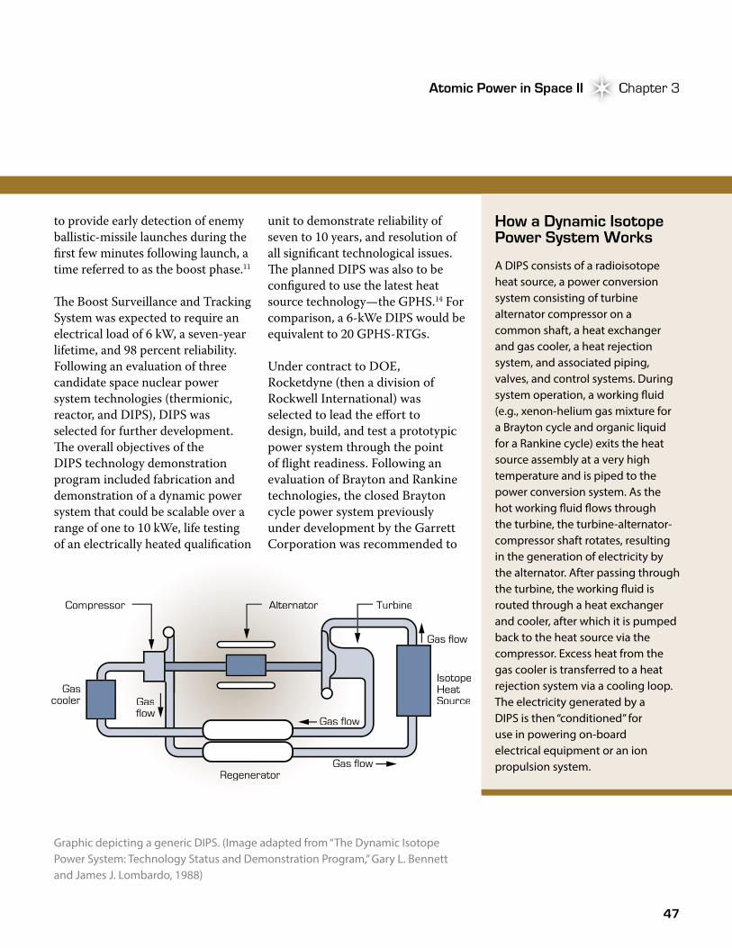
Graphic depicting a generic DIPS. (Image adapted from “The Dynamic Isotope Power System: Technology Status and Demonstration Program,” Gary L. Bennett and James J. Lombardo, 1988)
unit to demonstrate reliability of seven to 10 years, and resolution of all significant technological issues. �e planned DIPS was also to be configured to use the latest heat source technology—the GPHS.14 For comparison, a 6-kWe DIPS would be equivalent to 20 GPHS-RTGs.
Under contract to DOE, Rocketdyne (then a division of Rockwell International) was selected to lead the effort to design, build, and test a prototypic power system through the point of flight readiness. Following an evaluation of Brayton and Rankine technologies, the closed Brayton cycle power system previously under development by the Garrett Corporation was recommended to
How a Dynamic Isotope Power System Works
A DIPS consists of a radioisotope heat source, a power conversion system consisting of turbine alternator compressor on a common shaft, a heat exchanger and gas cooler, a heat rejection system, and associated piping, valves, and control systems. During system operation, a working �uid (e.g., xenon-helium gas mixture for a Brayton cycle and organic liquid for a Rankine cycle) exits the heat source assembly at a very high temperature and is piped to the power conversion system. As the hot working �uid �ows through the turbine, the turbine-alternator-compressor shaft rotates, resulting in the generation of electricity by the alternator. After passing through the turbine, the working �uid is routed through a heat exchanger and cooler, after which it is pumped back to the heat source via the compressor. Excess heat from the gas cooler is transferred to a heat rejection system via a cooling loop. The electricity generated by a DIPS is then “conditioned” for use in powering on-board electrical equipment or an ion propulsion system.
48
Advanced Isotope Power Systems Expanding RPS BoundariesAdvanced Isotope Power Systems
DOE for development. Following DOE concurrence, a Rockwell Garrett team designed a modular closed Brayton system with an anticipated power output of 2.5 kWe and an operating life of over 10 years.11 Although ground testing of the Brayton system never materialized (the program developing the Boost Surveillance and Tracking System decided against use of DIPS in favor of a non-isotope technology),15 the DIPS technology was soon connected to other space applications.
In 1989, President George H. W. Bush announced his Space Exploration Initiative (SEI). �e SEI had ambitious goals of returning humans to the moon within a decade and sending a manned crew to Mars by 2019. Within a year of the announcement, DOE and NASA had penned a memorandum of understanding that established a general framework by which the two agencies would cooperate on matters concerning information exchange and research and development activities under SEI.16
With the new NASA-DOE agreement, potential applications for a Brayton system soon shifted from the SDI effort to space-based exploration. Under the DIPS Demonstration Program, dynamic
power system concepts were developed to meet new missions and power levels for the exploration of space. For example, the closed Brayton cycle system was identified for possible use in planetary surface applications requiring 0.2 to 20 kWe.17 For a mission conceived to establish a manned outpost on the moon, a 2.5-We Brayton design was compared to other dynamic power system technologies, both nuclear and non-nuclear.18 In both concepts, planners assumed the use of a fueled GPHS module, the mainstay of DOE heat sources since its development for the Galileo and Ulysses missions.
While development of DIPS and other potential SEI power technology concepts began to grow, they soon came face-to-face with the reality that SEI lacked Congressional support and funding, largely due to its immense 20- to 30-year, $500-billion price tag. In the absence of the needed support,
the lofty human-exploration goals of SEI were soon abandoned and the DIPS Demonstration Program was brought to a close.19
Stirling Radioisotope Generators
By the mid-1990s, the need for an advanced radioisotope power system was becoming increasingly important to DOE and NASA. �e importance lay in the fact that the agencies had been faced with a limited inventory of plutonium-238 for over a decade following the shutdown of the K-Reactor at SRS in 1988.c Soon, interest in another dynamic power conversion system based on Stirling technology began to gain ground within DOE and NASA. �at interest had been fostered by years of Stirling technology research, including experience gained during development of the SP-100 space reactor power system.
While development of DIPS and other potential SEI power technology concepts began to grow, they soon came face-to-face with the reality that SEI lacked Congressional support and funding, largely due to its immense 20- to 30-year, $500-billion price tag.
c. See Chapter 10, Infrastructure Inroads. �e K-Reactor had provided for production of plutonium-238 for over 30 years. With its shut down, DOE lost its sole production capability for the heat source isotope.

49
Atomic Power in Space II Chapter 3Atomic Power in Space II Chapter 3
�e Stirling Technology Company, later named Infinia, was based in Kennewick, Washington, and had been working under contract to DOE to develop a 55-We Stirling engine called the technology demonstration convertor (TDC).d Following initial development and fabrication of multiple demonstration engines, the TDC was subjected to an extensive three-month evaluation that included testing for dynamic launch load capabilities, characterization of electromagnetic fields, and performance tests that measured parameters such as power output, system efficiency, and temperature. �e purpose of the DOE-sponsored evaluation, which began in late 1999, was to assess the technology readiness of the Stirling convertor relative to viability for a mission with a December 2004 launch date and its readiness for flight development. To support the evaluation, DOE tapped into the space nuclear power system expertise of NASA, Lockheed-Martin, Orbital Sciences Corporation, and others. At the conclusion of the three-month evaluation, the 55-We TDC won the support of the evaluation team as well as technology decision-makers within NASA and DOE, and follow-on development soon commenced.20
With the favorable results of the 55-We TDC assessment, DOE soon turned its efforts to development of a Stirling radioisotope generator (SRG). Following development of conceptual designs during a contract downselect phase, development of an SRG formally commenced in May 2002, when DOE selected Lockheed-Martin to serve as system integrator under a new project to develop an SRG capable of producing 110 We. Lockheed-Martin was responsible for the overall design, integration, and qualification of the planned Stirling power system, eventually dubbed the SRG-110. �e SRG-110 concept included use of the 55-We TDC under development by Infinia, which was responsible for convertor development, including design, fabrication, and testing. Technical expertise and support for development of the Stirling power system were provided by GRC. With a contract and project team in place, plans were laid to bring a flight-qualified Stirling RPS to fruition.21
As design of the Stirling generator progressed, fabrication and testing of TDCs continued in an effort to address manufacturability, performance, life, and reliability criteria. Much of the testing to support technology development, including convertor performance tests, thermal vacuum tests,
Stirling Engine Origins
Invention of the Stirling engine is generally attributed to Robert Stirling, a Scottish minister who invented the �rst practical closed-cycle air engine in 1816. Initially developed as a competitor for the steam engine in the 1800s, kinematic Stirling systems developed in the early- to mid-1900s were used in portable and marine generators and in various automotive and locomotive applications. In 1974, William Beale invented the free-piston Stirling engine, which found subsequent application in RPS concepts developed by DOE and NASA beginning in the mid-1990s.
materials studies, alternator testing, and structural-dynamics testing, was performed at the GRC.22 Such testing provided opportunities to address technical issues and refine the convertor design and supported overall integration with the Lockheed SRG design.23
By the end of 2005, Lockheed had designed a Stirling power system that could operate in the vacuum of deep space and on the surface of Mars. �e SRG-110 design consisted of a beryllium housing that contained two free-piston Stirling engines
d. �e NASA Stirling technology community uses the term “convertor” rather than “converter” when referring to Stirling power conversion. �at convention is reflected throughout this document as appropriate.
50
Advanced Isotope Power Systems Expanding RPS BoundariesAdvanced Isotope Power Systems
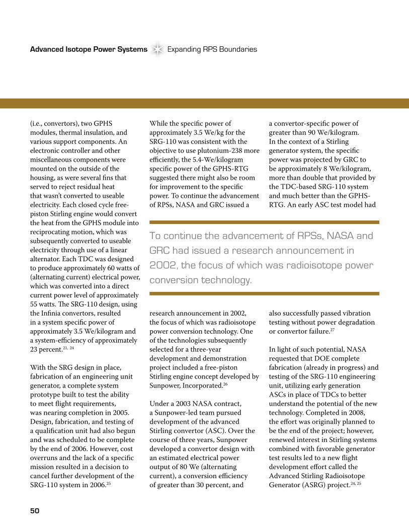
(i.e., convertors), two GPHS modules, thermal insulation, and various support components. An electronic controller and other miscellaneous components were mounted on the outside of the housing, as were several fins that served to reject residual heat that wasn’t converted to useable electricity. Each closed cycle free-piston Stirling engine would convert the heat from the GPHS module into reciprocating motion, which was subsequently converted to useable electricity through use of a linear alternator. Each TDC was designed to produce approximately 60 watts of (alternating current) electrical power, which was converted into a direct current power level of approximately 55 watts. �e SRG-110 design, using the Infinia convertors, resulted in a system specific power of approximately 3.5 We/kilogram and a system-efficiency of approximately 23 percent.21, 24
With the SRG design in place, fabrication of an engineering unit generator, a complete system prototype built to test the ability to meet flight requirements, was nearing completion in 2005. Design, fabrication, and testing of a qualification unit had also begun and was scheduled to be complete by the end of 2006. However, cost overruns and the lack of a specific mission resulted in a decision to cancel further development of the SRG-110 system in 2006.25
While the specific power of approximately 3.5 We/kg for the SRG-110 was consistent with the objective to use plutonium-238 more efficiently, the 5.4-We/kilogram specific power of the GPHS-RTG suggested there might also be room for improvement to the specific power. To continue the advancement of RPSs, NASA and GRC issued a
research announcement in 2002, the focus of which was radioisotope power conversion technology. One of the technologies subsequently selected for a three-year development and demonstration project included a free-piston Stirling engine concept developed by Sunpower, Incorporated.26
Under a 2003 NASA contract, a Sunpower-led team pursued development of the advanced Stirling convertor (ASC). Over the course of three years, Sunpower developed a convertor design with an estimated electrical power output of 80 We (alternating current), a conversion efficiency of greater than 30 percent, and
a convertor-specific power of greater than 90 We/kilogram. In the context of a Stirling generator system, the specific power was projected by GRC to be approximately 8 We/kilogram, more than double that provided by the TDC-based SRG-110 system and much better than the GPHS-RTG. An early ASC test model had
also successfully passed vibration testing without power degradation or convertor failure.27
In light of such potential, NASA requested that DOE complete fabrication (already in progress) and testing of the SRG-110 engineering unit, utilizing early generation ASCs in place of TDCs to better understand the potential of the new technology. Completed in 2008, the effort was originally planned to be the end of the project; however, renewed interest in Stirling systems combined with favorable generator test results led to a new flight development effort called the Advanced Stirling Radioisotope Generator (ASRG) project.24, 25
To continue the advancement of RPSs, NASA and GRC had issued a research announcement in 2002, the focus of which was radioisotope power conversion technology.
51
Atomic Power in Space II Chapter 3Atomic Power in Space II Chapter 3
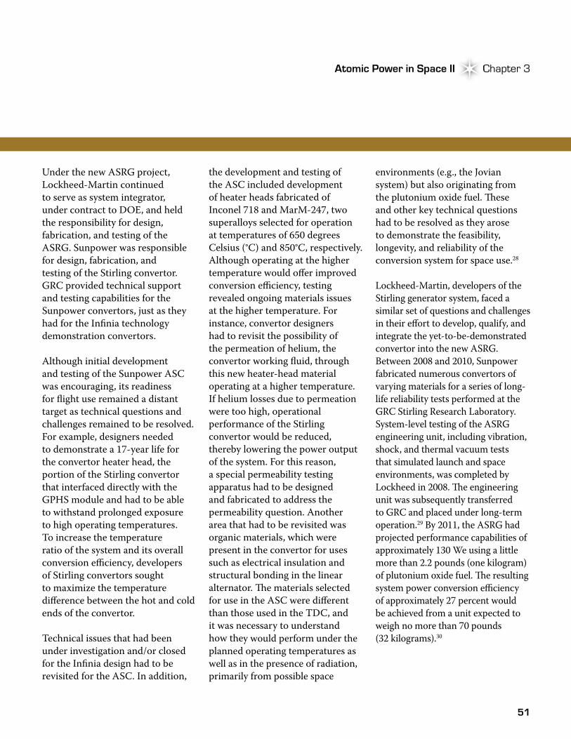
Under the new ASRG project, Lockheed-Martin continued to serve as system integrator, under contract to DOE, and held the responsibility for design, fabrication, and testing of the ASRG. Sunpower was responsible for design, fabrication, and testing of the Stirling convertor. GRC provided technical support and testing capabilities for the Sunpower convertors, just as they had for the Infinia technology demonstration convertors.
Although initial development and testing of the Sunpower ASC was encouraging, its readiness for flight use remained a distant target as technical questions and challenges remained to be resolved. For example, designers needed to demonstrate a 17-year life for the convertor heater head, the portion of the Stirling convertor that interfaced directly with the GPHS module and had to be able to withstand prolonged exposure to high operating temperatures. To increase the temperature ratio of the system and its overall conversion efficiency, developers of Stirling convertors sought to maximize the temperature difference between the hot and cold ends of the convertor.
Technical issues that had been under investigation and/or closed for the Infinia design had to be revisited for the ASC. In addition,
the development and testing of the ASC included development of heater heads fabricated of Inconel 718 and MarM-247, two superalloys selected for operation at temperatures of 650 degrees Celsius (°C) and 850°C, respectively. Although operating at the higher temperature would offer improved conversion efficiency, testing revealed ongoing materials issues at the higher temperature. For instance, convertor designers had to revisit the possibility of the permeation of helium, the convertor working fluid, through this new heater-head material operating at a higher temperature. If helium losses due to permeation were too high, operational performance of the Stirling convertor would be reduced, thereby lowering the power output of the system. For this reason, a special permeability testing apparatus had to be designed and fabricated to address the permeability question. Another area that had to be revisited was organic materials, which were present in the convertor for uses such as electrical insulation and structural bonding in the linear alternator. �e materials selected for use in the ASC were different than those used in the TDC, and it was necessary to understand how they would perform under the planned operating temperatures as well as in the presence of radiation, primarily from possible space
environments (e.g., the Jovian system) but also originating from the plutonium oxide fuel. �ese and other key technical questions had to be resolved as they arose to demonstrate the feasibility, longevity, and reliability of the conversion system for space use.28
Lockheed-Martin, developers of the Stirling generator system, faced a similar set of questions and challenges in their effort to develop, qualify, and integrate the yet-to-be-demonstrated convertor into the new ASRG. Between 2008 and 2010, Sunpower fabricated numerous convertors of varying materials for a series of long-life reliability tests performed at the GRC Stirling Research Laboratory. System-level testing of the ASRG engineering unit, including vibration, shock, and thermal vacuum tests that simulated launch and space environments, was completed by Lockheed in 2008. �e engineering unit was subsequently transferred to GRC and placed under long-term operation.29 By 2011, the ASRG had projected performance capabilities of approximately 130 We using a little more than 2.2 pounds (one kilogram) of plutonium oxide fuel. �e resulting system power conversion efficiency of approximately 27 percent would be achieved from a unit expected to weigh no more than 70 pounds (32 kilograms).30
52
Advanced Isotope Power Systems Expanding RPS BoundariesAdvanced Isotope Power Systems
As development of the ASRG progressed, NASA decided in 2011 that the ASRG development schedule should be consistent with supporting a future mission to be launched as early as January 2016; the decision added substantial schedule risk to the project.31 Due to the cost limits associated with Discovery missions, NASA also intended to provide the ASRG to the mission as government-furnished equipment.
In 2011, the ASRG design was subjected to a final design review that served to confirm system adequacy relative to specified performance and operational requirements.32 �e review led to
How an ASRG Works
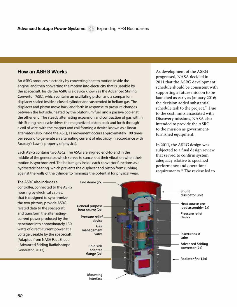
An ASRG produces electricity by converting heat to motion inside the engine, and then converting the motion into electricity that is useable by the spacecraft. Inside the ASRG is a device known as the Advanced Stirling Convertor (ASC), which contains an oscillating piston and a companion displacer sealed inside a closed cylinder and suspended in helium gas. The displacer and piston move back and forth in response to pressure changes between the hot side, heated by the plutonium fuel, and a passive cooler at the other end. The steady alternating expansion and contraction of gas within this Stirling heat cycle drives the magnetized piston back and forth through a coil of wire, with the magnet and coil forming a device known as a linear alternator (also inside the ASC), as movement occurs approximately 100 times per second to generate an alternating current of electricity in accordance with Faraday’s Law (a property of physics).
Each ASRG contains two ASCs. The ASCs are aligned end-to-end in the middle of the generator, which serves to cancel out their vibration when their motion is synchronized. The helium gas inside each convertor functions as a hydrostatic bearing, which prevents the displacer and piston from rubbing against the walls of the cylinder to minimize the potential for physical wear.
The ASRG also includes a controller, connected to the ASRG housing by electrical cables, that is designed to synchronize the two pistons, provide ASRG-related data to the spacecraft, and transform the alternating-current power produced by the generator into approximately 130 watts of direct-current power at a voltage useable by the spacecraft (Adapted from NASA Fact Sheet - Advanced Stirling Radioisotope Generator, 2013).
End dome (2x)
General purposeheat source (2x)
Pressure reliefdevice
Gas management
valve
Cold sideadapter
�ange (2x)
Mountinginterface
Heat source pre-load assembly (2x)
Shunt dissipator unit
Pressure reliefdevice
Interconnecttube
Advanced Stirlingconvertor (2x)
Radiator �n (12x)
53
Atomic Power in Space II Chapter 3Atomic Power in Space II Chapter 3
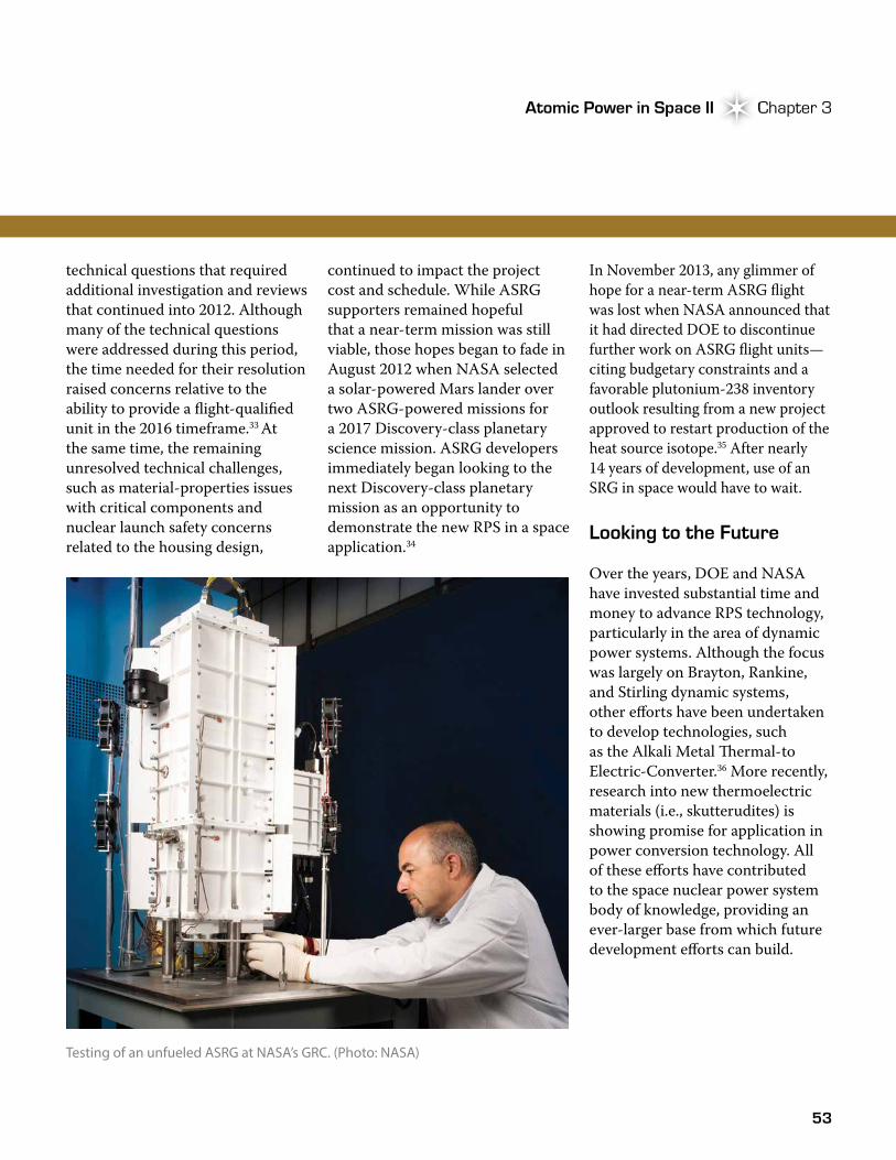
Testing of an unfueled ASRG at NASA’s GRC. (Photo: NASA)
technical questions that required additional investigation and reviews that continued into 2012. Although many of the technical questions were addressed during this period, the time needed for their resolution raised concerns relative to the ability to provide a flight-qualified unit in the 2016 timeframe.33 At the same time, the remaining unresolved technical challenges, such as material-properties issues with critical components and nuclear launch safety concerns related to the housing design,
continued to impact the project cost and schedule. While ASRG supporters remained hopeful that a near-term mission was still viable, those hopes began to fade in August 2012 when NASA selected a solar-powered Mars lander over two ASRG-powered missions for a 2017 Discovery-class planetary science mission. ASRG developers immediately began looking to the next Discovery-class planetary mission as an opportunity to demonstrate the new RPS in a space application.34
In November 2013, any glimmer of hope for a near-term ASRG flight was lost when NASA announced that it had directed DOE to discontinue further work on ASRG flight units—citing budgetary constraints and a favorable plutonium-238 inventory outlook resulting from a new project approved to restart production of the heat source isotope.35 After nearly 14 years of development, use of an SRG in space would have to wait.
Looking to the Future
Over the years, DOE and NASA have invested substantial time and money to advance RPS technology, particularly in the area of dynamic power systems. Although the focus was largely on Brayton, Rankine, and Stirling dynamic systems, other efforts have been undertaken to develop technologies, such as the Alkali Metal �ermal-to Electric-Converter.36 More recently, research into new thermoelectric materials (i.e., skutterudites) is showing promise for application in power conversion technology. All of these efforts have contributed to the space nuclear power system body of knowledge, providing an ever-larger base from which future development efforts can build.
54
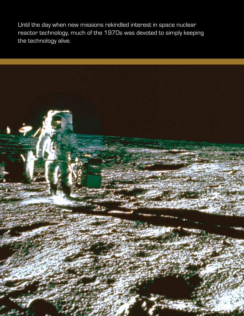
Until the day when new missions rekindled interest in space nuclear reactor technology, much of the 1970s was devoted to simply keeping the technology alive.
55Photo Credit
Reactors Redux Space Nuclear Reactor Interlude
Following termination of the NERVA nuclear rocket program and other space reactor research in 1973, the remainder of the decade was a dry time for space nuclear reactor technology development. Changing national priorities and reduced Federal budgets
hampered further research through much of the decade. At the same time, there were still strong incentives for use of space nuclear reactors. Apollo-era projects provided a solid foundation to build upon, and reactors had capabilities unmatched by competing technologies like solar power. �e greater power, compactness, and robustness of the technology could help the United States keep tabs on potential enemies, enable more civilian uses of satellites, and dramatically accelerate exploration of the outer solar system. Until the day when new missions rekindled interest in space nuclear reactor technology, much of the 1970s was devoted to simply keeping the technology alive.
Space Reactor Revival
Although space reactor research in the United States was defunded in 1973, a smaller space nuclear power program continued to operate with the majority of funding directed toward RPS development. During a hearing before the Joint Committee on Atomic Energy in March 1973, David Gabriel, Director of the Space Nuclear Systems Division at AEC, noted that space reactor research was terminated because of budget priorities and the lack of near term NASA missions requiring the power levels afforded by space nuclear reactors: “�ese projected [mission] delays, along with the budget priorities, led to the decision that the distant payoffs did not warrant continued funding of high-powered nuclear propulsion or reactor power systems.”1
Despite the end of large-scale space reactor development, the years that followed saw a small but ongoing effort to maintain the viability of space reactor technology.2 In addition, some space power energy conversion technologies found new life in ground-based power and transportation programs only to be resurrected years later in new space reactor programs. One example was the �ermionic Energy Conversion for Applied Research and Technology program, which researched the use of thermionic conversion to produce electricity using heat recovered
4
Apollo astronaut on the moon. Apollo-era projects provided a solid foundation to build upon, and reactors had capabilities unmatched by competing technologies like solar power. (Photo: NASA)
56
Reactors Redux Space Nuclear Reactor InterludeSpace Nuclear Reactor InterludeReactors Redux Reactors Redux
from coal-fired central power stations. In 1975, NASA broadened the program to include high temperature out-of-core nuclear thermionic power systems for future space applications.3
In 1973, AEC, DoD, and NASA formed an ad hoc group “…to evaluate the future DoD needs in space power and to indicate the possibility of meeting those needs with space [nuclear] power systems.”2 �e group’s final report, issued in March 1974, recommended preserving the reactor technology developed under the SNAP program and stimulating “a focused space power program for earlier payoffs on DoD missions.”2
�e focused space power program began to take shape in 1975 when DoD and the newly-formed ERDA, the successor agency to AEC, established a Space Nuclear Applications Steering Group. Chaired by George P. Dix, former head of the AEC space nuclear safety program,4 the group was tasked to establish effective management and communication channels between the agencies in order “to encourage a proper development program for space nuclear energy systems.”2 In concert with the steering group, DoD and ERDA also established a space nuclear power working group in
early 1976. �e working group was tasked to
study future DoD space power requirements to determine which applications would best
be served by nuclear power systems and to
recommend a space power technology development program.5
In August 1976, DoD Steering Group Chairman A.E. Vossberg sent a letter to Richard W. Roberts, ERDA’s Assistant Administrator for Nuclear Energy, stating, “In our continuing effort to ensure that future space power requirements of the DoD can be met on a timely basis, I wish to call your attention to the growing likelihood of need for space nuclear reactor systems in the 10 to 100 kW electric range in the late 1980s and beyond.”2
By 1977, the Steering Group had identified several DoD missions with power requirements up to 100 kWe. Comparing reactors to their main space competition, solar-battery power, the group found that for military missions, solar panels coupled with batteries were competitive with nuclear in the range of 25 to 50 kWe; nuclear power was judged to be superior above power levels of 50 kWe. With several potential DoD missions needing 25 kWe or more, particularly a space-based radar system planned by the Air
Force, the case for a renewed space reactor development program continued to gain traction, as noted by the Steering Group in January 1977:
“Although the Steering Group has been unable to identify any approved and budgeted DoD missions (requiring greater than 3 kWe)… a reactor power supply is presently the only candidate spacecraft power option for future high power applications. �is fact, combined with data on space reactor power capabilities outside the U.S., the enhanced military capability provided by having sufficient power to operate on-orbit equipment such as radar, and future threats to our space defense posture afforded by similar high power capabilities in the hands of adversaries, has led the Steering Group to recommend that a reactor power development program be initiated by the U.S. following intensive preparatory studies to define the reactor power system and its requirements.”2
Additional support for a renewed space reactor development program was provided by the space power system working group when it recommended a “modest technology and experimental program to provide a solid basis from which to develop space reactors.”5 �e recommendations soon bore fruit.
57
Atomic Power in Space II Chapter 4Atomic Power in Space II Chapter 4
Space Electric Power Supply Program
In 1977, DoD and ERDA initiated a joint technology-screening study to evaluate existing space reactor power system technologies and develop a space reactor power system concept for further development. �e study was performed by LASL under a new Space Electric Power Supply program.6,7 With the advent of the planned Space Transportation System, or space shuttle (under development since 1972), a new era of space use and exploration was expected to open up and, along with it, larger space-based systems that would require higher power, thereby giving impetus to the new space reactor efforts.8
Although the technology screening study was initiated under ERDA, it would be completed under a new Federal agency. Only 20 months after the formation of ERDA, its almost 9,000 employees were consolidated into the newly created DOE, which combined ERDA with other energy-related Federal organizations. George
Dix became the Director of Safety and Environmental Operations within the new Federal agency4 and Bernard Rock became the Director of the Office of Space Nuclear Projects. �e Space Electric Power Supply program continued under the Nuclear Energy Programs group within the Assistant Secretary of Energy Technology organization in the new DOE.7
�e screening study included the identification of several DoD missions that could require power levels up to 100 kWe, such as satellites and space-based radar, many of which were expected to be needed by the early 1990s. DoD required a seven-year lifetime and 95 percent reliability, preferring
designs that would degrade only gradually and avoid the potential for a single fault to cause the whole system to fail (such a failure is often referred to as a single-point failure). �e reactor had to be able to operate in Earth’s natural radiation fields, and radiation created by the system had to be limited both in rate and amount
delivered over the mission lifetime. �e reactor was also expected to meet all regulations of NASA, DoD, DOE, and the National Range Commanders in charge of the sites where the system would be launched.5
In addition to the potential DoD missions, studies by Grumman and McDonnell Douglas identified commercial industrial-scale low-earth-orbit missions that were likely to require a space nuclear power system. One mission envisioned a construction site in space to build solar- or nuclear-powered satellites that would send energy to Earth. Another was a low-gravity manufacturing facility. �e studies also proposed a civilian version of the military’s new GPS and scientific missions focused toward the stars and planets.5 For NASA, potential applications included communication and surveillance systems, electronic mail, and advanced television antenna systems for which five to 220 kWe was expected, and planetary exploration missions requiring even higher power levels.
Based on a target power level of 10 to 100 kWe, LASL developed 135 reactor power plant combinations that reflected a suite of reactor designs, electric-power-conversion technologies, and heat rejection systems. �e reactor designs included heat pipe, gas-cooled, and
With the advent of the planned Space Transportation System, or space shuttle (under development since 1972), a new era of space use and exploration was expected to open up.
58
Reactors Redux Space Nuclear Reactor InterludeSpace Nuclear Reactor Interlude
liquid-metal concepts, while fuel types included uranium carbide, uranium oxide, and uranium nitride. Several power conversion technologies were evaluated, including static (thermoelectric and thermionic) and dynamic (Brayton, potassium Rankine, and Stirling) systems. Heat rejection options included heat pipes, pumped fluid with fin radiators, and pumped fluid with heat pipe radiators. After consideration against criteria that
included weight, size, reliability, safety, and development cost and time, LASL recommended a technology development program based on a concept consisting of a heat pipe solid-core reactor with thermoelectric power conversion, and a heat pipe radiator.5
As the LASL technology study progressed, an accident involving a Russian space reactor power system provided a somber reminder of the
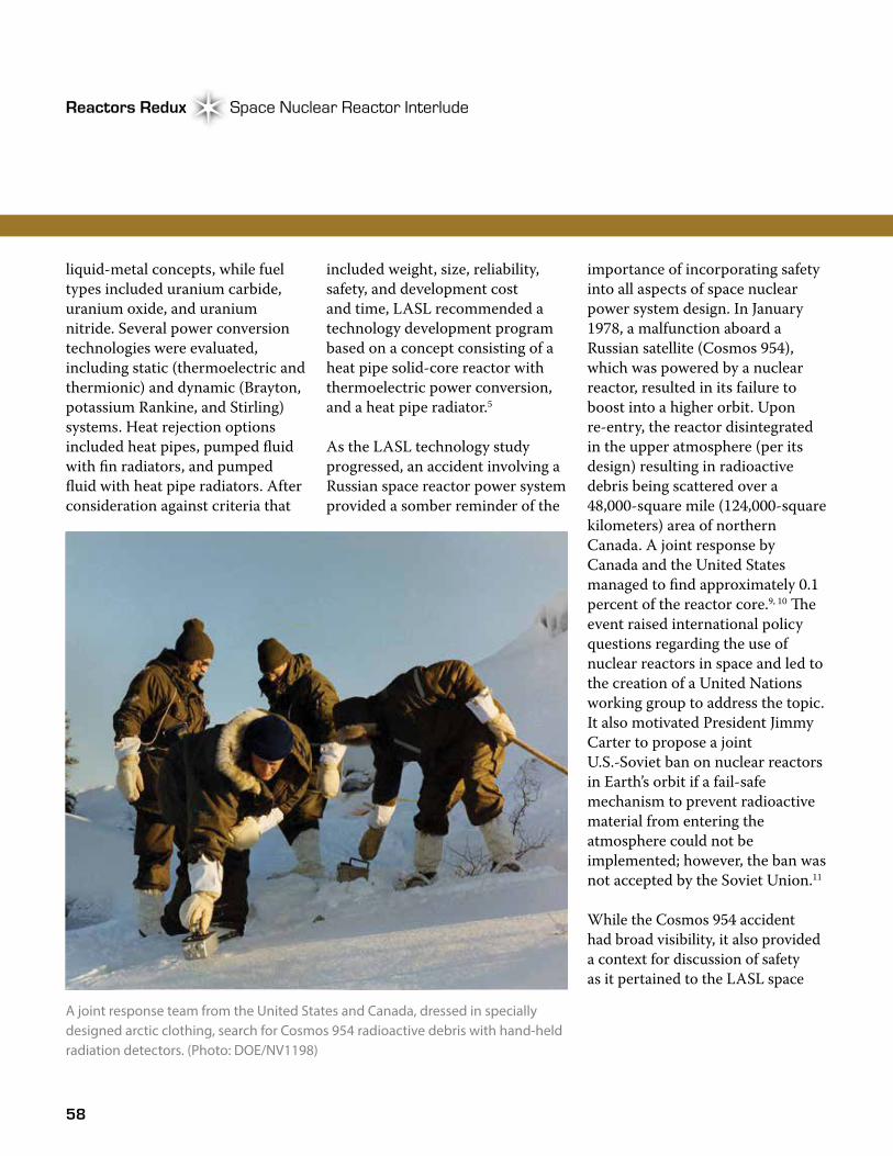
importance of incorporating safety into all aspects of space nuclear power system design. In January 1978, a malfunction aboard a Russian satellite (Cosmos 954), which was powered by a nuclear reactor, resulted in its failure to boost into a higher orbit. Upon re-entry, the reactor disintegrated in the upper atmosphere (per its design) resulting in radioactive debris being scattered over a 48,000-square mile (124,000-square kilometers) area of northern Canada. A joint response by Canada and the United States managed to find approximately 0.1 percent of the reactor core.9, 10 �e event raised international policy questions regarding the use of nuclear reactors in space and led to the creation of a United Nations working group to address the topic. It also motivated President Jimmy Carter to propose a joint U.S.-Soviet ban on nuclear reactors in Earth’s orbit if a fail-safe mechanism to prevent radioactive material from entering the atmosphere could not be implemented; however, the ban was not accepted by the Soviet Union.11
While the Cosmos 954 accident had broad visibility, it also provided a context for discussion of safety as it pertained to the LASL space
Reactors Redux Reactors Redux
A joint response team from the United States and Canada, dressed in specially designed arctic clothing, search for Cosmos 954 radioactive debris with hand-held radiation detectors. (Photo: DOE/NV1198)
59
Atomic Power in Space II Chapter 4Atomic Power in Space II Chapter 4
Heat Pipe Technology
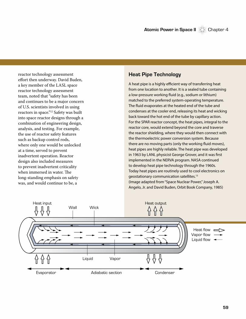
A heat pipe is a highly e�cient way of transferring heat from one location to another. It is a sealed tube containing a low-pressure working �uid (e.g., sodium or lithium) matched to the preferred system-operating temperature. The �uid evaporates at the heated end of the tube and condenses at the cooler end, releasing its heat and wicking back toward the hot end of the tube by capillary action. For the SPAR reactor concept, the heat pipes, integral to the reactor core, would extend beyond the core and traverse the reactor shielding, where they would then connect with the thermoelectric power conversion system. Because there are no moving parts (only the working �uid moves), heat pipes are highly reliable. The heat pipe was developed in 1963 by LANL physicist George Grover, and it was �rst implemented in the NERVA program. NASA continued to develop heat pipe technology through the 1960s. Today heat pipes are routinely used to cool electronics on geostationary communication satellites.13 (Image adapted from “Space Nuclear Power,” Joseph A. Angelo, Jr. and David Buden, Orbit Book Company, 1985)
Heat input Heat output
Heat flowVapor flowLiquid flow
Wall Wick
VaporLiquid
Evaporator Adiabatic section Condenser
reactor technology assessment effort then underway. David Buden, a key member of the LASL space reactor technology assessment team, noted that “safety has been and continues to be a major concern of U.S. scientists involved in using reactors in space.”12 Safety was built into space reactor designs through a combination of engineering design, analysis, and testing. For example, the use of reactor safety features such as backup control rods, where only one would be unlocked at a time, served to prevent inadvertent operation. Reactor design also included measures to prevent inadvertent criticality when immersed in water. �e long-standing emphasis on safety was, and would continue to be, a

60
Reactors Redux Space Nuclear Reactor InterludeSpace Nuclear Reactor Interlude
fundamental aspect of U.S. space reactor power system development, including the space reactor work being performed at LASL.
Space Power Advanced Reactor
In late 1979, DOE initiated a five-year program to develop the technology base of the heat-pipe reactor power system recommended by LASL. With funding of $2 million per year, the goal was to develop a space reactor system capable of producing 10
to 100 kWe. �e LASL heat pipe reactor power system concept was subsequently named SPAR.14,15 Concurrent with the DOE activities, NASA also began funding work on heat pipe and power conversion development, both at LASL and their own facilities. In early 1980, DOE and NASA joined with DoD to create a steering committee and space reactor working group to bring some unity to the DOE-funded SPAR effort and NASA’s own space reactor work (the groups worked together until 1981).2
By 1981, an initial design for SPAR had been developed. �e reactor was being designed to produce a nominal 1,200 kW of thermal power while operating at 1,500 Kelvin. �e reactor design incorporated a core of 90 uranium oxide sodium-filled heat pipe fuel element modules. �e heat pipes would remove thermal energy from the reactor core and transfer it to the thermoelectric power conversion system. For compatibility with the space shuttle power system, the mass would be less than 4,210 pounds (1,910 kilograms).16
�e core was to be surrounded by a neutron reflector of beryllium or beryllium oxide, which would control reactor operation. As with the NERVA program, rotating drums were to be used for power control; each drum would contain a boron carbide sector that could be rotated in and out of the reactor to control reactivity. Redundant instrumentation and electronics would increase reliability, which was considered as important as safety, and the reactor had to keep operating even if some components failed.
For the thermoelectric power conversion system, LASL planned to use an improved version of the
Reactors Redux Reactors Redux
Concept of a heat pipe nuclear reactor coupled directly to thermoelectric converters. The heat pipes extend from the reactor core (bottom left of image) and carry heat to the thermoelectric converter. Excess heat not converted to electricity is transferred to the radiator via a second set of heat pipes. (Image: LANL)
61
Atomic Power in Space II Chapter 4Atomic Power in Space II Chapter 4
silicon-germanium thermoelectric materials used in the MHW-RTGs that powered the Voyagers 1 and 2 spacecraft; the improved silicon-germanium material, then under development by DOE, contained gallium phosphide and offered the potential for higher conversion efficiency. Excess heat would be radiated to space through the use of a heat pipe radiator system. A shadow radiation shield design was also drawn from the earlier SNAP and Rover reactors. Because the reactor was to be used in space where there is no air to deflect neutrons and gamma rays around the shield, weight could be reduced by placing the reactor and payload at opposite ends of the spacecraft with shielding in between, instead of shielding the whole reactor.
By 1982, the SPAR technology development program had evolved into a broad testing, experimental, and analytical program centered on the reactor, heat pipes, thermoelectric materials, and shielding. For example, predictions of neutron behavior in the reactor core were experimentally checked using a critical assembly. Analyses were
also performed to demonstrate the reactor would remain safely sub-critical in the event of immersion in water. Fuel development focused on production processes for the uranium oxide fuel and in-reactor testing to verify fuel performance and heat transfer characteristics. Development of the molybdenum heat pipes included materials testing, wick design development, development of processes to bend the heat pipes, and performance testing for compatibility with working fluids. For the power conversion system, activities focused on development of silicon-germanium thermoelectric modules (i.e., panels) that would interface with the heat rejection system heat pipes.17,18
Because the space shuttle was to be the primary method of launching systems into space, reactor power system designers also had to ensure that the spacecraft and its reactor power system would fit in the shuttle cargo bay, a cylinder 60 feet (18.3 meters) long and 15 feet (4.6 meters) in diameter. When an upper stage launch vehicle was factored into the spacecraft
configuration, the available room in the shuttle could be reduced to 42 feet (12.8 meters) long and 14 feet (4.3 meters) in diameter.19
Defining Roles and Goals: Establishing Cooperation
As the technology effort progressed, the future of its funding soon came into question. During the formulation of its fiscal year 1982 budget, DOE was directed by the Office of Management and Budget to reduce its funding for space reactor development to $1 million, thereby putting DoD and NASA on the hook to fund the shortfall. Although DoD opted out of funding, NASA
Reagan National Space Policy
In July 1982, President Ronald Reagan announced his National Space Policy, which was intended to strengthen U.S. security, expand private-sector investment, and increase exploitation of resources and international cooperation. The 1982 policy established the space shuttle as a major factor in the U.S. program and called on NASA to continue exploring the “requirements, operational concepts, and technology” needed to support permanent space facilities – a space station. 20
Excess heat would be radiated to space through the use of a heat pipe radiator system.
62
Reactors Redux Space Nuclear Reactor InterludeSpace Nuclear Reactor Interlude
agreed to support the project and work with DOE toward a joint technology verification phase; NASA mission models had indicated that 100 kWe was suitable for both outer-planetary and earth-orbital missions. Because of the budgetary constraints at DOE, NASA also assumed responsibility for development of the power conversion subsystem while DOE retained responsibility for development of the reactor subsystem, with funding support from NASA.15 �e arrangement marked a change from previous joint NASA-DOE approaches under which DOE was solely responsible for funding reactor technology development.3
Shortly after NASA became a co-sponsor of the SPAR technology development program, it was named the Space Nuclear Reactor Power Systems Technology Program and the SPAR reactor was renamed SP-100 (for Space Power 100 kWe).2, 15 �e SPAR reactor design was also refined to ensure its compatibility with the space shuttle and to raise its temperature and energy density.21 �e new program goals were similar to those outlined for the original SPAR design and included full-power operation at 100 kWe for seven years, with an overall system life of 10 years, and no single-point failures.2
Although the technology development program had shifted to support NASA, groups within DoD continued to maintain an interest in a space reactor power system. In addition to its attractiveness for space-based radar, surveillance, communications, electric propulsion, and jammers, such systems offered other benefits, as noted by Gordon L. Chipman, DOE Deputy Assistant Secretary for Breeder Reactor Programs (and oversaw its Office of Space Reactor Projects):
“[N]uclear power enhances survivability against nuclear attack, laser attack, and antisatellite attack. It also makes it practical to provide the payload with high power, which enhances survivability by permitting higher orbits, more ground links, harder electronics, smaller antennas, and mobile ground receivers. Nuclear power also provides the spacecraft with an improved field of view and improved pointing accuracy and permits undegraded operation in the Van Allen radiation belts.”15
With the continued interest in space power reactors, DOE separated its Office of Space Nuclear Projects into an Office of Special Applications focused on RPS technology and an Office of Space Reactor Projects.22
The National Research Council Lends a Hand
In the months that followed the conception of the DOE NASA SP-100 reactor, the agencies began working with the Defense Advanced Research Projects Agency (DARPA) to establish a joint program for development of a 100-kWe space reactor system. Disagreements over management, organization, and program goals soon led to tension. For a short time in late 1982, NASA began working with DARPA under a project called the Technology for Advanced Space Power program,
Reactors Redux Reactors Redux
Although the technology development program had shifted to support NASA, groups within DoD continued to maintain an interest in a space reactor power system.

63
Atomic Power in Space II Chapter 4Atomic Power in Space II Chapter 4
leaving DOE to continue work on technology for the SP-100 reactor.21
As the three agencies struggled to find common ground, the Departments of the Army, Navy, and Air Force; DARPA; and NASA sponsored the National Research Council in October 1982 to assess the state-of-the-art advanced nuclear power systems with possible aerospace applications in the area of propulsion, including shielding and safety problems. �e Council was also asked to describe research gaps and areas of uncertainty in space nuclear power system technology and to make recommendations for future
development efforts. To accomplish its task, the committee responsible for the assessment organized a symposium on advanced reactor concepts in November 1982. �e symposium offered an opportunity for experts throughout the space nuclear power community to discuss space power technology concepts, safety, research and development issues, and mission requirements for both space reactor power and propulsion systems. It also provided the basis upon which the committee developed its assessment and recommendations for future space nuclear power technology development efforts.23
In its final report, the space nuclear power assessment committee noted that a government-wide joint space reactor power system program was appropriate because both the military and civilian agencies had future power needs that could only be met with reactors. Failure to act would mean a higher bill later for a crash program or simply not having the needed technology at all. �e report also included assessments of several items that had been cause for earlier frustration and tension among the agencies, including funding and research program goals, and provided an assessment of the LASL heat pipe reactor.24
�e report accurately described a chicken-and-egg dilemma that DoD, NASA, and DOE had been facing in deciding whether and how to proceed:
“Most research and development managers would like to be in a situation in which a user (with resources) can specify with precision a requirement that can serve as the target for a technical development effort. However, experienced technical managers recognize that such a linear situation rarely obtains [sic], especially in circumstances in which long lead times and expensive development efforts are required. Prudent program managers are reluctant to risk or expose large scale resources
Space Nuclear Power Symposiums
In the fall of 1982, a small group of government, industry, and academic representatives, including University of New Mexico professors Dr. Mohamed EI-Genk and Dr. David Woodall, decided to hold an annual symposium on space nuclear power systems due to growing interest in such systems within the Federal government. The �rst symposium, held in 1983, was enthusiastically received by the space nuclear power community. Though initially small, the annual symposium brie�y rose to prominence several years later. After a decade of obscurity, limited funding, and slow development, space nuclear reactors were again on the front burner of U.S. space power research.
Failure to act would mean a higher bill later for a crash program or simply not having the needed technology at all.
64
Reactors Redux Space Nuclear Reactor InterludeReactors Redux Space Nuclear Reactor Interlude
to achieve stated requirements until the viability of the technology is sufficiently well established to provide a reasonable prospect that the requirement can be met at estimated costs. On the other hand, major resources for research and development programs cannot be easily justified to those who control funds unless a firm requirement exists. �e inevitable result of such a situation is no action unless research and development programs can be launched and pursued with a realistic acceptance of the uncertainty…”.25
�e report also weighed in on the question of which agencies should pay for the needed research and development:
“Potential Air Force and NASA users are loath to adopt a requirement prior to demonstration of the technology from a concern about… a large development bill, perhaps in the range of $500 million to $1 billion. Yet most managers of space systems programs recognize that the future… points toward nuclear power…�e military users should recognize that someone will need to bear the research and development cost for the operational capability they will require. Accordingly, these users should recognize that the desired capability will not be forthcoming unless they are more supportive of these initial research and development efforts.”26
On the subject of the DOE-NASA SP-100 reactor, the report noted that the LASL design was of high quality but “not sufficiently unique or demonstrably superior to alternative concepts to justify selection of this approach.”27 �e report identified several areas that still required significant development before a full ground test could be pursued, most notably in the heat pipes (fabrication, performance, and longevity), reactor (fuel behavior and actuator performance), and high-temperature thermoelectric performance. For these reasons, the committee urged that alternative concepts “be brought to a stage in which they can be evaluated relative to the SP-100 on a similar basis.”
In light of its assessment, the final report recommended a research and development program be funded at a level of $10 to $15 million per year to develop a 100-kWe space power reactor as a generic multi-use development, not tied to a specific mission. �e recommendation came with a
warning: “�e major lesson from this history is the importance of approximately matching the research and development effort to the process of emergence of a firm requirement. �e committee seeks to avoid a massive research and development program that never meets the needs or resource availability of military or civil space users.”28
In February 1983, DOE, NASA, and DARPA finally came together and signed a tri-agency memorandum of agreement to take action along the lines of the National Research Council recommendations.29 �e agreement called for the three agencies to assess and advance the technology for 100-kWe and multi-megawatt (MMW) space nuclear power systems, provide engineering development and production systems for users, and ensure nuclear safety. Under the new agreement, the agencies carried the DOE-NASA SP-100 name into a new space reactor development program that would be the largest since the days of Rover/NERVA.
“The committee seeks to avoid a massive research and development program that never meets the needs or resource availability of military or civil space users.”28
65
Atomic Power in Space II Chapter 4Atomic Power in Space II Chapter 4
The Interlude Gives Way
�e 10-year period that followed the termination of the Rover/NERVA program seemingly served as an interlude for U.S. space reactor development. Efforts were aimed at keeping the technology moving forward. Although seemingly buried, the prospects of power and other benefits afforded by a space reactor power system brought about a renewed development effort focused on a heat pipe reactor that served to expand the base on which future space reactor work could build. �e desire for space reactor power also provided the impetus by which the broader space nuclear power system technical community was brought together to share technology status, concepts, and information. �at gathering gave rise to what would become a decade-long annual event that eventually expanded to include international partners. At its conclusion in 1983, the interlude had given way to the SP-100 program, a new movement in the concerto of space reactor power system development (discussed in Chapter 5). As for the LASL heat pipe reactor system concept, it was carried into the technology assessment phase of the new SP-100 program but eventually was set aside in favor of other technologies.
66
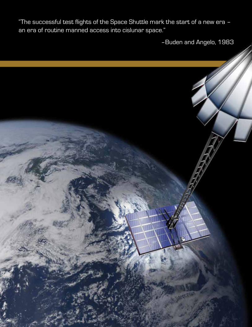
Intro text“The successful test flights of the Space Shuttle mark the start of a new era – an era of routine manned access into cislunar space.”
–Buden and Angelo, 1983
67
0
Photo Credit
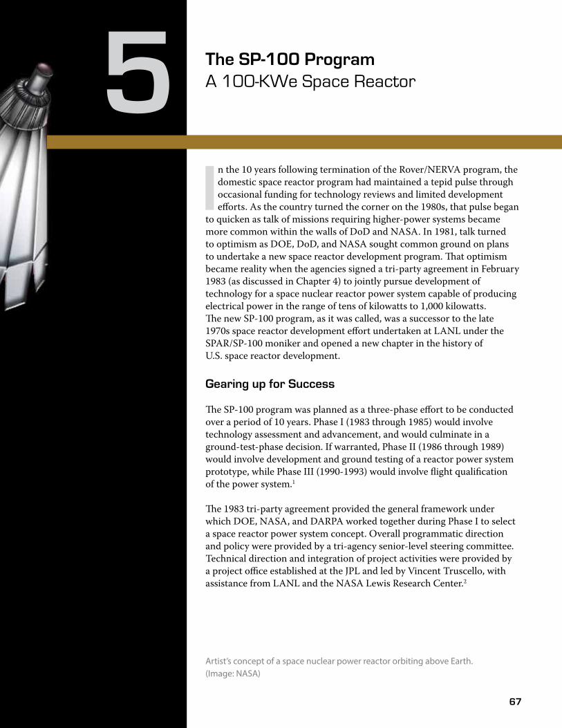
The SP-100 Program A 100-KWe Space Reactor5I
n the 10 years following termination of the Rover/NERVA program, the domestic space reactor program had maintained a tepid pulse through occasional funding for technology reviews and limited development efforts. As the country turned the corner on the 1980s, that pulse began
to quicken as talk of missions requiring higher-power systems became more common within the walls of DoD and NASA. In 1981, talk turned to optimism as DOE, DoD, and NASA sought common ground on plans to undertake a new space reactor development program. �at optimism became reality when the agencies signed a tri-party agreement in February 1983 (as discussed in Chapter 4) to jointly pursue development of technology for a space nuclear reactor power system capable of producing electrical power in the range of tens of kilowatts to 1,000 kilowatts. �e new SP-100 program, as it was called, was a successor to the late 1970s space reactor development effort undertaken at LANL under the SPAR/SP-100 moniker and opened a new chapter in the history of U.S. space reactor development.
Gearing up for Success
�e SP-100 program was planned as a three-phase effort to be conducted over a period of 10 years. Phase I (1983 through 1985) would involve technology assessment and advancement, and would culminate in a ground-test-phase decision. If warranted, Phase II (1986 through 1989) would involve development and ground testing of a reactor power system prototype, while Phase III (1990-1993) would involve flight qualification of the power system.1
�e 1983 tri-party agreement provided the general framework under which DOE, NASA, and DARPA worked together during Phase I to select a space reactor power system concept. Overall programmatic direction and policy were provided by a tri-agency senior-level steering committee. Technical direction and integration of project activities were provided by a project office established at the JPL and led by Vincent Truscello, with assistance from LANL and the NASA Lewis Research Center.2
Artist’s concept of a space nuclear power reactor orbiting above Earth. (Image: NASA)
68
The SP-100 Program 100-KWe Space ReactorThe SP-100 Program
To support the technology assessment and development activities during Phase I, a generic set of performance criteria were established for the planned SP-100 system. �e criteria included a power output of 100 kWe; a design lifetime of 10 years, with seven years at full power; a maximum system mass of 6,600 pounds (3,000 kilograms); and a maximum length of 20 feet (6.1 meters). �e length criterion was associated with the space shuttle cargo bay, which was to be used to launch the space reactor into orbit. �e power system would also need to be scalable to higher or lower power levels without major design changes.2 Although generic in nature, the power system criteria provided broad targets for evaluation and design of candidate SP-100 power system concepts.
With the assistance of three contractors (GA Technologies, Rockwell, and GE), JPL was responsible to review candidate power system concepts and recommend one concept that could meet expected civilian and military mission requirements. Research to advance nuclear technology, such as fuels and materials research, was performed at DOE laboratories, including LANL, ORNL, and Argonne National Laboratory-West (ANL-W). �e DOE Energy Technology Engineering Center, located in Los Angeles, California,
performed support test-facility work.3 �e Lewis Research Center provided support in areas of mission analysis, with particular emphasis on space shuttle missions and development of technologies such as energy conversion, thermal management, and space power materials and structures under an advanced technology program.4
Missions, Power Systems, and Technology
With funding of approximately $15 million per year, Phase I of the SP-100 program consisted of three core tasks: (1) definition of potential DoD and NASA missions that might require nuclear power, (2) evaluation of reactor power system concepts that could meet mission requirements, and (3) technology advancement (including testing and analyses) to address areas of technical uncertainty. Of primary concern from the outset was the need to ensure nuclear safety was properly addressed throughout the entire program, including Phase I. �erefore, a
safety-evaluation program was established to ensure the reactor system concepts and the technology supporting those concepts would not result in designs that would lead to unacceptable nuclear safety risks. Phase I also included an effort to evaluate candidate DOE sites for reactor-power-system ground testing suitability.2
Linking the SP-100 power system to a specific mission was crucial for justifying the program and establishing design goals. Such linkage was also a necessity to ensure long-term funding and support. Indeed, history had shown that while previous space reactor development efforts, such as the Rover/NERVA program, had demonstrated a high measure of technical success, the absence of a definitive mission could preclude ever going operational.5 To that end, review groups were established by DoD and NASA to perform mission analyses and requirement studies early in the first phase. Workshops provided an avenue to discuss mission needs
Linking the SP-100 power system to a specific mission was crucial for justifying the program and establishing design goals. Such linkage was also a necessity to ensure long-term funding and support.
69
Atomic Power in Space II Chapter 5Atomic Power in Space II Chapter 5
in the context of technology and power requirements.6 Several generic missions were eventually identified. DoD anticipated power demands up to 100 kWe for robust surveillance systems, survivable communications with anti-jamming capabilities, and electric propulsion systems for orbital transfer and space-based weapons applications. NASA anticipated nuclear electric propulsion and power needs up to 50 kWe for uses such as interplanetary missions, an Earth-orbiting tug, and manned space stations and planetary bases.7
Cold War Concerns
Throughout much of the 1980s, Russian space nuclear activities continued to be a source of military and international concern, which provided impetus for the SP-100 program. Soviet surveillance satellites were designed to detach from their reactor power sources at the end of their missions, after which the reactor was to be boosted into a higher orbit, delaying re-entry for hundreds of years while �ssion products decayed to a safe level. In early 1983, the reactor from the Russian Cosmos 1402 spy satellite, launched in August 1982, separated from the satellite but the booster rocket failed to �re. As a result, the reactor reentered Earth’s atmosphere in February 1983 over the South Atlantic
Ocean.9 Although not as serious as the re-entry of Cosmos 954 over Canada in 1978, at least in terms of response and cleanup, the event highlighted concerns about Russian space reactor technology, as noted by Mr. Herman Roser of DOE, during an address to the National Research Council on June 15, 1983:
“While the nuclear Navy is an outstanding example of the use of nuclear reactors to achieve defense energy security, we have not fared as well in our [space] reactor programs… On space reactors, we lag the Soviets by 10 years… Two Soviet nuclear-powered satellites were over the Falklands [during the war between Great Britain and
Argentina] according to Defense Daily. My people were involved in two Soviet space emergencies: the Cosmos 954 reactor emergency in Canada in 1978, and the recent Cosmos 1402 reactor re-entry this January. It requires only a little imagination to be concerned with what the Soviets are doing in space today and what they will be capable of doing in the future, with their advantages in space nuclear power, given their possession of hardened multi-hundred kilowatt or megawatt nuclear reactors in orbit.”10
In the area of technology development, Phase I activities focused on a broad range of testing and experiments to advance technology that was common to multiple reactor systems or had applications beyond the SP-100 program. For example, in-core reactor-life testing of thermionic diodes was initiated to demonstrate the potential for a seven-year life. Research was initiated in high-temperature thermoelectric materials. Compatibility testing of reactor construction materials and reactor coolants was conducted. Fabrication and life testing of refractory metal heat pipes was also
initiated. LANL re-established a production capability for uranium nitride fuel elements, lost since the SNAP-50 program in the 1960s, and continued efforts to demonstrate a fabrication capability for refractory metal fuel pins.2 In the area of power-conversion technology, the Lewis Research Center initiated a Space Power Demonstrator Engine project to demonstrate the feasibility of a 25-kWe free piston Stirling engine for possible use with the SP-100 system.8
As technology development and mission analysis progressed, so did the development and evaluation
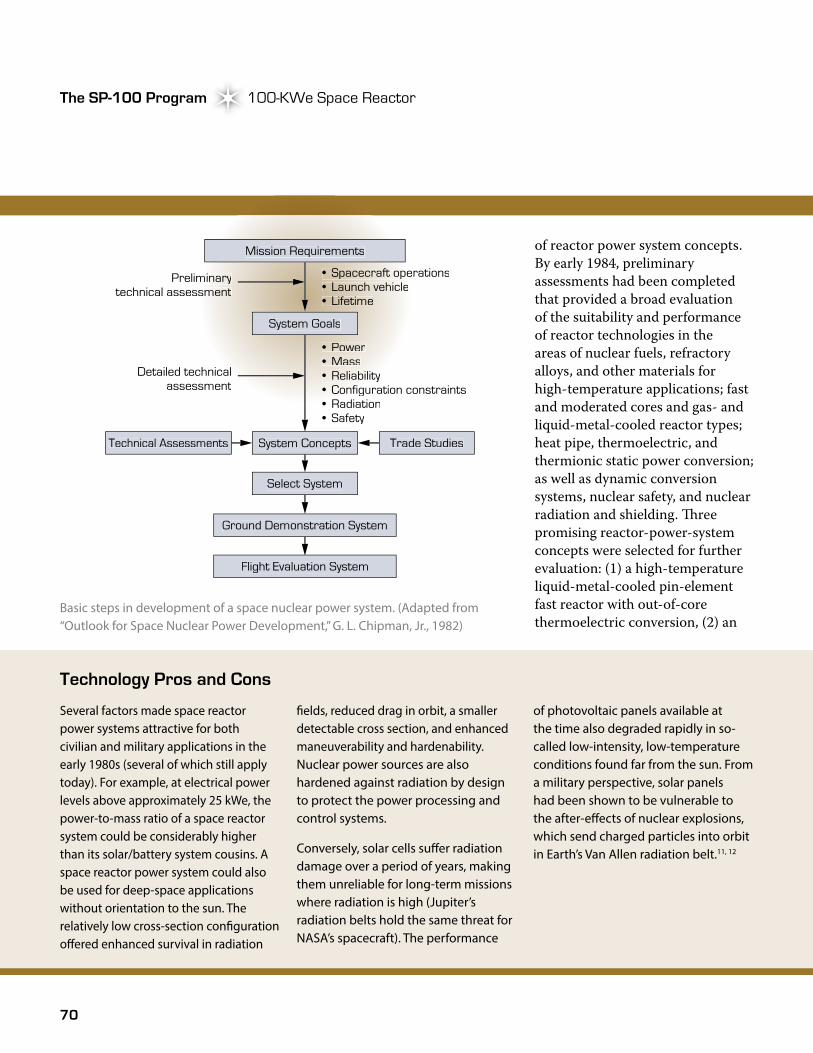
70
The SP-100 Program 100-KWe Space ReactorThe SP-100 Program
Technology Pros and Cons
Several factors made space reactor power systems attractive for both civilian and military applications in the early 1980s (several of which still apply today). For example, at electrical power levels above approximately 25 kWe, the power-to-mass ratio of a space reactor system could be considerably higher than its solar/battery system cousins. A space reactor power system could also be used for deep-space applications without orientation to the sun. The relatively low cross-section con�guration o�ered enhanced survival in radiation
�elds, reduced drag in orbit, a smaller detectable cross section, and enhanced maneuverability and hardenability. Nuclear power sources are also hardened against radiation by design to protect the power processing and control systems.
Conversely, solar cells su�er radiation damage over a period of years, making them unreliable for long-term missions where radiation is high (Jupiter’s radiation belts hold the same threat for NASA’s spacecraft). The performance
of photovoltaic panels available at the time also degraded rapidly in so-called low-intensity, low-temperature conditions found far from the sun. From a military perspective, solar panels had been shown to be vulnerable to the after-e�ects of nuclear explosions, which send charged particles into orbit in Earth’s Van Allen radiation belt.11, 12
of reactor power system concepts. By early 1984, preliminary assessments had been completed that provided a broad evaluation of the suitability and performance of reactor technologies in the areas of nuclear fuels, refractory alloys, and other materials for high-temperature applications; fast and moderated cores and gas- and liquid-metal-cooled reactor types; heat pipe, thermoelectric, and thermionic static power conversion; as well as dynamic conversion systems, nuclear safety, and nuclear radiation and shielding. �ree promising reactor-power-system concepts were selected for further evaluation: (1) a high-temperature liquid-metal-cooled pin-element fast reactor with out-of-core thermoelectric conversion, (2) an
Basic steps in development of a space nuclear power system. (Adapted from “Outlook for Space Nuclear Power Development,” G. L. Chipman, Jr., 1982)
Mission Requirements
System Goals
System Concepts Trade Studies
Select System
Ground Demonstration System
Flight Evaluation System
• Power• Mass• Reliability• Reliability• Configuration constraints• Configuration constraints• Radiation• Radiation• Safety
PreliminaryPreliminarytechnical assessmenttechnical assessment
Detailed technicalDetailed technicalassessment
Technical Assessments
• Spacecraft operations• Spacecraft operations• Launch vehicle• Lifetime

71
Atomic Power in Space II Chapter 5Atomic Power in Space II Chapter 5
in-core thermionic fast reactor power system, and (3) a low-temperature pin-element reactor with Stirling power conversion. In August 1985, following a detailed systems study of the power system concepts, the fast reactor thermoelectric power conversion system was selected for follow-on development during Phase II.7
Although the thermoelectric technology offered lower power-conversion efficiency than the thermionic and Stirling technologies, it represented the lowest technical risk of the three options due to the technology having been successfully used in RTGs for several decades. For this reason, the Interagency Steering Committee selected the thermoelectric reactor power system for further engineering development and ground testing based, in part, on the judgment that it was the only technology that could be ready for flight system development by the end of fiscal year 1991 at a cost of less than $500 million. Other factors that influenced the decision included operating life and weight. Robert Wiley, who worked on the SP-100 for the Strategic Defense Initiative Organization (SDIO), which replaced DARPA in directing the SP-100 program beginning in Phase II, recalled, “One of the key things
that drove the decision was that Bill Wright [of DARPA] in particular was adamant… [that] mass was the key. And in order to find an actual application, the unit had to be relatively lightweight.”13 After three years and a cost of approximately $51 million, Phase I was completed in September 1985.14
�e design power level was subsequently returned to 100 kWe approximately one year later.15
While the power-level decision introduced questions of technical feasibility, the thermoelectric choice was not unanimously supported and divisions began
The Air Force people, for the most part, were adamant that thermionics was the right answer.
Separate Directions
Concurrent with the decision to proceed with the thermoelectric-based reactor power system, the Interagency Steering Committee decided to increase the ground-test power level from 100 kWe to 300 kWe to meet evolving DoD needs, based primarily on an Air Force recommendation.12 �e decision introduced a small problem for developers of the reactor power system—the higher power level was technically incompatible with the capabilities of the thermoelectric system. In spite of the technical incompatibility, program inertia and the political risk associated with going back to another round of technology selection kept the program moving forward.
forming in the program. “�e Air Force people, for the most part, were adamant that thermionics was the right answer. �ey were very unhappy about the decision to go thermoelectric…and so some were actually contemplating filing a formal dissent to their decision but they opted not to do that…” noted Wiley.13 After much discussion with the thermionics advocates, DOE and SDIO initiated an in-core thermionics development program called the �ermionic Fuel Element (TFE) Verification Program.e NASA also started another program to develop a high-temperature Stirling engine that would be able to produce five times the output of the thermoelectric converter with the SP-100 reactor. Despite the original intent to focus
e. �e TFE Verification Program is discussed in detail in Chapter 7, �ermionics Revisited.
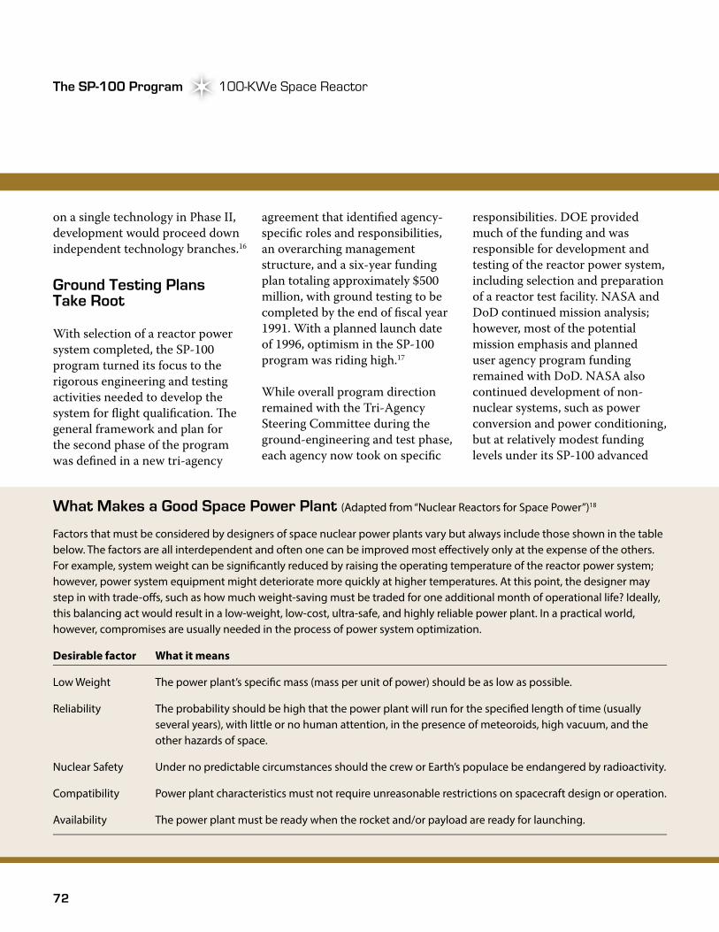
72
The SP-100 Program 100-KWe Space ReactorThe SP-100 Program
on a single technology in Phase II, development would proceed down independent technology branches.16
Ground Testing Plans Take Root
With selection of a reactor power system completed, the SP-100 program turned its focus to the rigorous engineering and testing activities needed to develop the system for flight qualification. �e general framework and plan for the second phase of the program was defined in a new tri-agency
What Makes a Good Space Power Plant (Adapted from “Nuclear Reactors for Space Power”)18
Factors that must be considered by designers of space nuclear power plants vary but always include those shown in the table below. The factors are all interdependent and often one can be improved most e�ectively only at the expense of the others. For example, system weight can be signi�cantly reduced by raising the operating temperature of the reactor power system; however, power system equipment might deteriorate more quickly at higher temperatures. At this point, the designer may step in with trade-o�s, such as how much weight-saving must be traded for one additional month of operational life? Ideally, this balancing act would result in a low-weight, low-cost, ultra-safe, and highly reliable power plant. In a practical world, however, compromises are usually needed in the process of power system optimization.
Desirable factor What it means
Low Weight The power plant’s speci�c mass (mass per unit of power) should be as low as possible.
Reliability The probability should be high that the power plant will run for the speci�ed length of time (usually several years), with little or no human attention, in the presence of meteoroids, high vacuum, and the other hazards of space.
Nuclear Safety Under no predictable circumstances should the crew or Earth’s populace be endangered by radioactivity.
Compatibility Power plant characteristics must not require unreasonable restrictions on spacecraft design or operation.
Availability The power plant must be ready when the rocket and/or payload are ready for launching.
agreement that identified agency-specific roles and responsibilities, an overarching management structure, and a six-year funding plan totaling approximately $500 million, with ground testing to be completed by the end of fiscal year 1991. With a planned launch date of 1996, optimism in the SP-100 program was riding high.17
While overall program direction remained with the Tri-Agency Steering Committee during the ground-engineering and test phase, each agency now took on specific
responsibilities. DOE provided much of the funding and was responsible for development and testing of the reactor power system, including selection and preparation of a reactor test facility. NASA and DoD continued mission analysis; however, most of the potential mission emphasis and planned user agency program funding remained with DoD. NASA also continued development of non-nuclear systems, such as power conversion and power conditioning, but at relatively modest funding levels under its SP-100 advanced
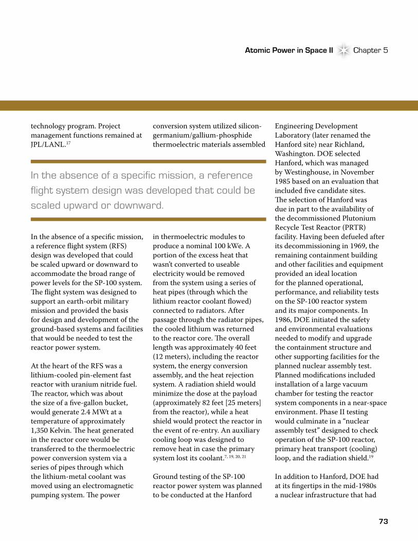
73
Atomic Power in Space II Chapter 5Atomic Power in Space II Chapter 5
technology program. Project management functions remained at JPL/LANL.17
In the absence of a specific mission, a reference flight system (RFS) design was developed that could be scaled upward or downward to accommodate the broad range of power levels for the SP-100 system. �e flight system was designed to support an earth-orbit military mission and provided the basis for design and development of the ground-based systems and facilities that would be needed to test the reactor power system.
At the heart of the RFS was a lithium-cooled pin-element fast reactor with uranium nitride fuel. �e reactor, which was about the size of a five-gallon bucket, would generate 2.4 MWt at a temperature of approximately 1,350 Kelvin. �e heat generated in the reactor core would be transferred to the thermoelectric power conversion system via a series of pipes through which the lithium-metal coolant was moved using an electromagnetic pumping system. �e power
conversion system utilized silicon-germanium/gallium-phosphide thermoelectric materials assembled
in thermoelectric modules to produce a nominal 100 kWe. A portion of the excess heat that wasn’t converted to useable electricity would be removed from the system using a series of heat pipes (through which the lithium reactor coolant flowed) connected to radiators. After passage through the radiator pipes, the cooled lithium was returned to the reactor core. �e overall length was approximately 40 feet (12 meters), including the reactor system, the energy conversion assembly, and the heat rejection system. A radiation shield would minimize the dose at the payload (approximately 82 feet [25 meters] from the reactor), while a heat shield would protect the reactor in the event of re-entry. An auxiliary cooling loop was designed to remove heat in case the primary system lost its coolant.7, 19, 20, 21
Ground testing of the SP-100 reactor power system was planned to be conducted at the Hanford
Engineering Development Laboratory (later renamed the Hanford site) near Richland, Washington. DOE selected Hanford, which was managed by Westinghouse, in November 1985 based on an evaluation that included five candidate sites. �e selection of Hanford was due in part to the availability of the decommissioned Plutonium Recycle Test Reactor (PRTR)facility. Having been defueled after its decommissioning in 1969, the remaining containment building and other facilities and equipment provided an ideal location for the planned operational, performance, and reliability tests on the SP-100 reactor system and its major components. In 1986, DOE initiated the safety and environmental evaluations needed to modify and upgrade the containment structure and other supporting facilities for the planned nuclear assembly test. Planned modifications included installation of a large vacuum chamber for testing the reactor system components in a near-space environment. Phase II testing would culminate in a “nuclear assembly test” designed to check operation of the SP-100 reactor, primary heat transport (cooling) loop, and the radiation shield.19
In addition to Hanford, DOE had at its fingertips in the mid-1980s a nuclear infrastructure that had
In the absence of a specific mission, a reference flight system design was developed that could be scaled upward or downward.
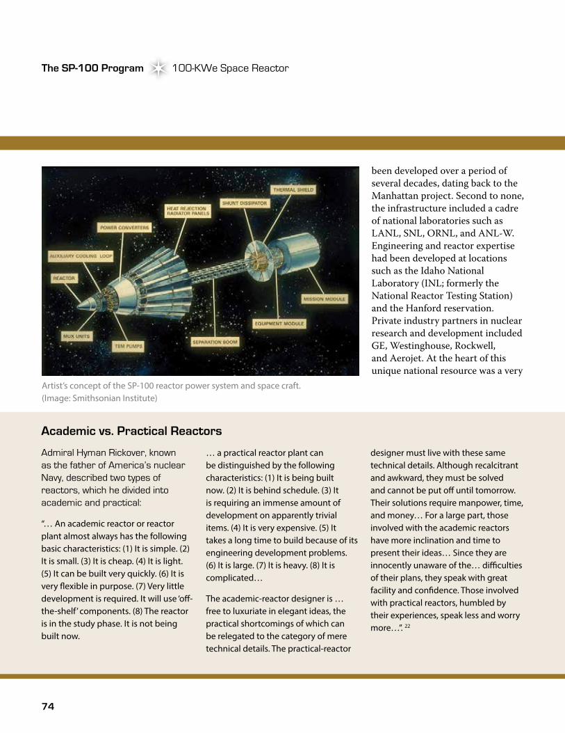
74
The SP-100 Program 100-KWe Space ReactorThe SP-100 Program
been developed over a period of several decades, dating back to the Manhattan project. Second to none, the infrastructure included a cadre of national laboratories such as LANL, SNL, ORNL, and ANL-W. Engineering and reactor expertise had been developed at locations such as the Idaho National Laboratory (INL; formerly the National Reactor Testing Station) and the Hanford reservation. Private industry partners in nuclear research and development included GE, Westinghouse, Rockwell, and Aerojet. At the heart of this unique national resource was a very
Academic vs. Practical Reactors
Admiral Hyman Rickover, known as the father of America’s nuclear Navy, described two types of reactors, which he divided into academic and practical:
“… An academic reactor or reactor plant almost always has the following basic characteristics: (1) It is simple. (2) It is small. (3) It is cheap. (4) It is light. (5) It can be built very quickly. (6) It is very �exible in purpose. (7) Very little development is required. It will use ‘o�-the-shelf’ components. (8) The reactor is in the study phase. It is not being built now.
… a practical reactor plant can be distinguished by the following characteristics: (1) It is being built now. (2) It is behind schedule. (3) It is requiring an immense amount of development on apparently trivial items. (4) It is very expensive. (5) It takes a long time to build because of its engineering development problems. (6) It is large. (7) It is heavy. (8) It is complicated…
The academic-reactor designer is … free to luxuriate in elegant ideas, the practical shortcomings of which can be relegated to the category of mere technical details. The practical-reactor
designer must live with these same technical details. Although recalcitrant and awkward, they must be solved and cannot be put o� until tomorrow. Their solutions require manpower, time, and money… For a large part, those involved with the academic reactors have more inclination and time to present their ideas… Since they are innocently unaware of the… di�culties of their plans, they speak with great facility and con�dence. Those involved with practical reactors, humbled by their experiences, speak less and worry more…”. 22
Artist’s concept of the SP-100 reactor power system and space craft. (Image: Smithsonian Institute)
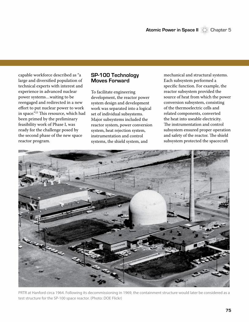
75
Atomic Power in Space II Chapter 5Atomic Power in Space II Chapter 5
capable workforce described as “a large and diversified population of technical experts with interest and experience in advanced nuclear power systems…waiting to be reengaged and redirected in a new effort to put nuclear power to work in space.”23 �is resource, which had been primed by the preliminary feasibility work of Phase I, was ready for the challenge posed by the second phase of the new space reactor program.
SP-100 Technology Moves Forward
To facilitate engineering development, the reactor power system design and development work was separated into a logical set of individual subsystems. Major subsystems included the reactor system, power conversion system, heat rejection system, instrumentation and control systems, the shield system, and
mechanical and structural systems. Each subsystem performed a specific function. For example, the reactor subsystem provided the source of heat from which the power conversion subsystem, consisting of the thermoelectric cells and related components, converted the heat into useable electricity. �e instrumentation and control subsystem ensured proper operation and safety of the reactor. �e shield subsystem protected the spacecraft
PRTR at Hanford circa 1964. Following its decommissioning in 1969, the containment structure would later be considered as a test structure for the SP-100 space reactor. (Photo: DOE Flickr)
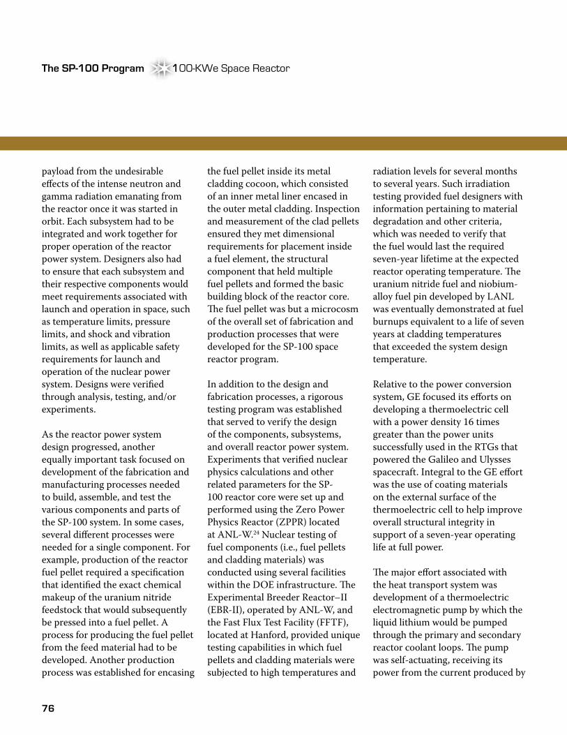
76
The SP-100 Program 100-KWe Space ReactorThe SP-100 Program
payload from the undesirable effects of the intense neutron and gamma radiation emanating from the reactor once it was started in orbit. Each subsystem had to be integrated and work together for proper operation of the reactor power system. Designers also had to ensure that each subsystem and their respective components would meet requirements associated with launch and operation in space, such as temperature limits, pressure limits, and shock and vibration limits, as well as applicable safety requirements for launch and operation of the nuclear power system. Designs were verified through analysis, testing, and/or experiments.
As the reactor power system design progressed, another equally important task focused on development of the fabrication and manufacturing processes needed to build, assemble, and test the various components and parts of the SP-100 system. In some cases, several different processes were needed for a single component. For example, production of the reactor fuel pellet required a specification that identified the exact chemical makeup of the uranium nitride feedstock that would subsequently be pressed into a fuel pellet. A process for producing the fuel pellet from the feed material had to be developed. Another production process was established for encasing
the fuel pellet inside its metal cladding cocoon, which consisted of an inner metal liner encased in the outer metal cladding. Inspection and measurement of the clad pellets ensured they met dimensional requirements for placement inside a fuel element, the structural component that held multiple fuel pellets and formed the basic building block of the reactor core. �e fuel pellet was but a microcosm of the overall set of fabrication and production processes that were developed for the SP-100 space reactor program.
In addition to the design and fabrication processes, a rigorous testing program was established that served to verify the design of the components, subsystems, and overall reactor power system. Experiments that verified nuclear physics calculations and other related parameters for the SP-100 reactor core were set up and performed using the Zero Power Physics Reactor (ZPPR) located at ANL-W.24 Nuclear testing of fuel components (i.e., fuel pellets and cladding materials) was conducted using several facilities within the DOE infrastructure. �e Experimental Breeder Reactor–II (EBR-II), operated by ANL-W, and the Fast Flux Test Facility (FFTF), located at Hanford, provided unique testing capabilities in which fuel pellets and cladding materials were subjected to high temperatures and
radiation levels for several months to several years. Such irradiation testing provided fuel designers with information pertaining to material degradation and other criteria, which was needed to verify that the fuel would last the required seven-year lifetime at the expected reactor operating temperature. �e uranium nitride fuel and niobium-alloy fuel pin developed by LANL was eventually demonstrated at fuel burnups equivalent to a life of seven years at cladding temperatures that exceeded the system design temperature.
Relative to the power conversion system, GE focused its efforts on developing a thermoelectric cell with a power density 16 times greater than the power units successfully used in the RTGs that powered the Galileo and Ulysses spacecraft. Integral to the GE effort was the use of coating materials on the external surface of the thermoelectric cell to help improve overall structural integrity in support of a seven-year operating life at full power.
�e major effort associated with the heat transport system was development of a thermoelectric electromagnetic pump by which the liquid lithium would be pumped through the primary and secondary reactor coolant loops. �e pump was self-actuating, receiving its power from the current produced by
100-KWe Space ReactorThe SP-100 Program

77
Atomic Power in Space II Chapter 5Atomic Power in Space II Chapter 5
thermoelectric cells located between the primary and secondary coolant loops that passed through the pump.
Closely related to pump development was the need to ensure the lithium coolant (in solid form before system operation) was thawed in a manner that would allow the pump to operate as designed. In addition to demonstrating assembly techniques, the project team validated its hydraulic and electromagnetic performance through a series of pump tests. Testing of the pump and other major SP-100 subsystems, such as the thermoelectric power conversion and heat rejection systems, was performed using a
non-nuclear heat source similar to what was done with the GPHS-RTG.
Tensions Mount
While significant technical progress was made during the first several years of Phase II, financial clouds began to form over the SP-100 program in 1986. Spurred by the Graham-Rudman-Hollings Deficit Reduction Act of 1985, the Federal government began a broad tightening of its fiscal belt. �e fiscal tightening translated into reduced funding for all Federal agencies, and the SP-100 program was hit particularly hard. During the first four years of Phase II (1986-1989), the agencies received and/
or contributed only $260 million of the approximately $450 million planned per the Phase II tri-agency agreement. At the agency level, the funding levels equated to $160 million of $210 million planned for DOE (a 25 percent reduction), $82 million of $220 million planned by SDIO (a 60 percent reduction), and $19.9 million of the $16 million planned for NASA. �e situation didn’t improve in 1990 or 1991, as appropriations continued to lag the funding plan. In addition to reduced funding levels for the agencies, the SP-100 program experienced significant cost growth due to ongoing technical issues, thereby worsening the fiscal outlook for the program.25
In the wake of the eroding financial picture, major program changes soon followed. �e ground engineering system and technology development activities were delayed, shifting the planned completion date from 1992 to 1994, and then later from 1994 to 2002. �e tri-agency agreement was updated more than once to reflect the changing funding and schedule realities.25 As a result of the funding problems and schedule delays, frustration began to mount, particularly within SDIO, the primary mission organization and source of the major SP-100 program funding reductions.
SP-100 core mockup in the ZPPR at ANL-W. (Photo: INL)
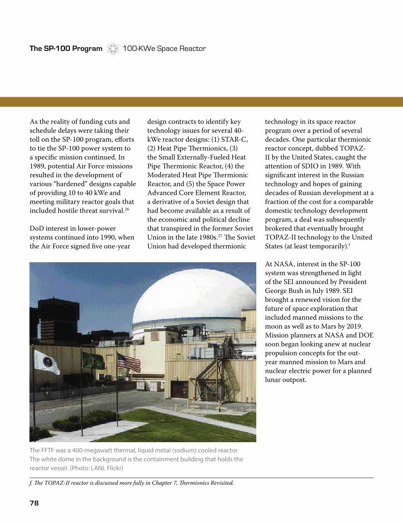
78
The SP-100 Program 100-KWe Space ReactorThe SP-100 Program
As the reality of funding cuts and schedule delays were taking their toll on the SP-100 program, efforts to tie the SP-100 power system to a specific mission continued. In 1989, potential Air Force missions resulted in the development of various “hardened” designs capable of providing 10 to 40 kWe and meeting military reactor goals that included hostile threat survival.26
DoD interest in lower-power systems continued into 1990, when the Air Force signed five one-year
design contracts to identify key technology issues for several 40-kWe reactor designs: (1) STAR-C, (2) Heat Pipe �ermionics, (3) the Small Externally-Fueled Heat Pipe �ermionic Reactor, (4) the Moderated Heat Pipe �ermionic Reactor, and (5) the Space Power Advanced Core Element Reactor, a derivative of a Soviet design that had become available as a result of the economic and political decline that transpired in the former Soviet Union in the late 1980s.27 �e Soviet Union had developed thermionic
technology in its space reactor program over a period of several decades. One particular thermionic reactor concept, dubbed TOPAZ-II by the United States, caught the attention of SDIO in 1989. With significant interest in the Russian technology and hopes of gaining decades of Russian development at a fraction of the cost for a comparable domestic technology development program, a deal was subsequently brokered that eventually brought TOPAZ-II technology to the United States (at least temporarily).f
At NASA, interest in the SP-100 system was strengthened in light of the SEI announced by President George Bush in July 1989. SEI brought a renewed vision for the future of space exploration that included manned missions to the moon as well as to Mars by 2019. Mission planners at NASA and DOE soon began looking anew at nuclear propulsion concepts for the out-year manned mission to Mars and nuclear electric power for a planned lunar outpost.
The FFTF was a 400-megawatt thermal, liquid metal (sodium) cooled reactor. The white dome in the background is the containment building that holds the reactor vessel. (Photo: LANL Flickr)
f. �e TOPAZ-II reactor is discussed more fully in Chapter 7, �ermionics Revisited.
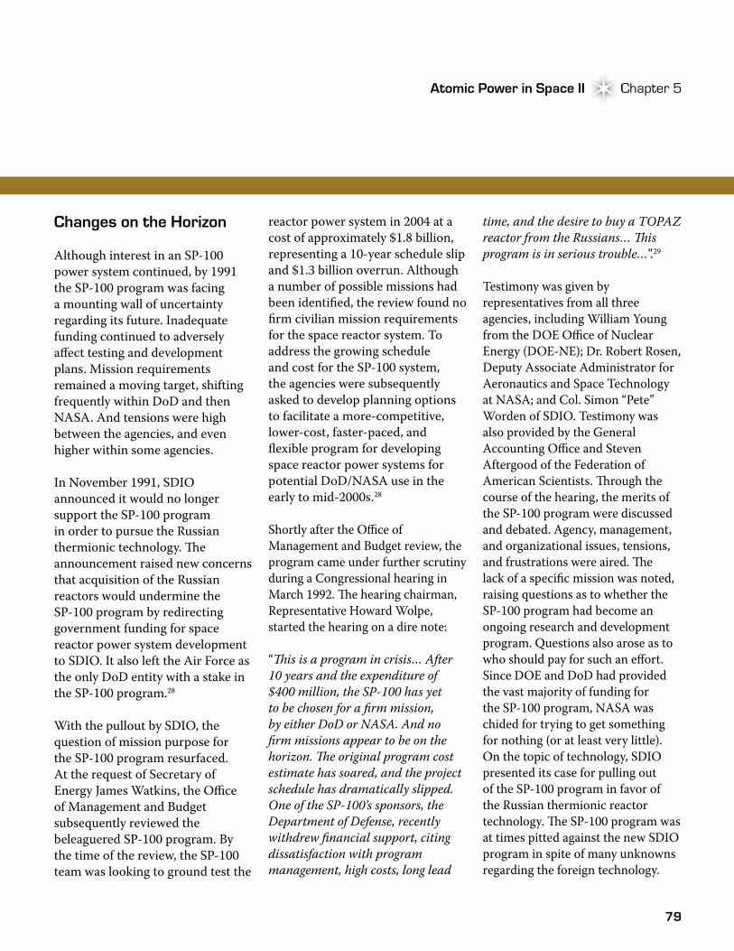
79
Atomic Power in Space II Chapter 5Atomic Power in Space II Chapter 5
Changes on the Horizon
Although interest in an SP-100 power system continued, by 1991 the SP-100 program was facing a mounting wall of uncertainty regarding its future. Inadequate funding continued to adversely affect testing and development plans. Mission requirements remained a moving target, shifting frequently within DoD and then NASA. And tensions were high between the agencies, and even higher within some agencies.
In November 1991, SDIO announced it would no longer support the SP-100 program in order to pursue the Russian thermionic technology. �e announcement raised new concerns that acquisition of the Russian reactors would undermine the SP-100 program by redirecting government funding for space reactor power system development to SDIO. It also left the Air Force as the only DoD entity with a stake in the SP-100 program.28
With the pullout by SDIO, the question of mission purpose for the SP-100 program resurfaced. At the request of Secretary of Energy James Watkins, the Office of Management and Budget subsequently reviewed the beleaguered SP-100 program. By the time of the review, the SP-100 team was looking to ground test the
reactor power system in 2004 at a cost of approximately $1.8 billion, representing a 10-year schedule slip and $1.3 billion overrun. Although a number of possible missions had been identified, the review found no firm civilian mission requirements for the space reactor system. To address the growing schedule and cost for the SP-100 system, the agencies were subsequently asked to develop planning options to facilitate a more-competitive, lower-cost, faster-paced, and flexible program for developing space reactor power systems for potential DoD/NASA use in the early to mid-2000s.28
Shortly after the Office of Management and Budget review, the program came under further scrutiny during a Congressional hearing in March 1992. �e hearing chairman, Representative Howard Wolpe, started the hearing on a dire note:
“�is is a program in crisis… After 10 years and the expenditure of $400 million, the SP-100 has yet to be chosen for a firm mission, by either DoD or NASA. And no firm missions appear to be on the horizon. �e original program cost estimate has soared, and the project schedule has dramatically slipped. One of the SP-100’s sponsors, the Department of Defense, recently withdrew financial support, citing dissatisfaction with program management, high costs, long lead
time, and the desire to buy a TOPAZ reactor from the Russians… �is program is in serious trouble…”.29
Testimony was given by representatives from all three agencies, including William Young from the DOE Office of Nuclear Energy (DOE-NE); Dr. Robert Rosen, Deputy Associate Administrator for Aeronautics and Space Technology at NASA; and Col. Simon “Pete” Worden of SDIO. Testimony was also provided by the General Accounting Office and Steven Aftergood of the Federation of American Scientists. �rough the course of the hearing, the merits of the SP-100 program were discussed and debated. Agency, management, and organizational issues, tensions, and frustrations were aired. �e lack of a specific mission was noted, raising questions as to whether the SP-100 program had become an ongoing research and development program. Questions also arose as to who should pay for such an effort. Since DOE and DoD had provided the vast majority of funding for the SP-100 program, NASA was chided for trying to get something for nothing (or at least very little). On the topic of technology, SDIO presented its case for pulling out of the SP-100 program in favor of the Russian thermionic reactor technology. �e SP-100 program was at times pitted against the new SDIO program in spite of many unknowns regarding the foreign technology.
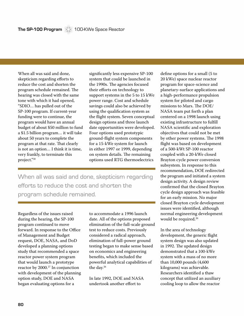
80
The SP-100 Program 100-KWe Space ReactorThe SP-100 Program
When all was said and done, skepticism regarding efforts to reduce the cost and shorten the program schedule remained. �e hearing was closed with the same tone with which it had opened, “SDIO… has pulled out of the SP-100 program. If current-year funding were to continue, the program would have an annual budget of about $50 million to fund a $1.5 billion program… it will take about 50 years to complete the program at that rate. �at clearly is not an option… I think it is time, very frankly, to terminate this project.”30
Regardless of the issues raised during the hearing, the SP-100 program continued to move forward. In response to the Office of Management and Budget request, DOE, NASA, and DoD developed a planning options study that recommended a space reactor power system program that would launch a prototype reactor by 2000.27 In conjunction with development of the planning option study, DOE and NASA began evaluating options for a
significantly less expensive SP-100 system that could be launched in the 1990s. �e agencies focused their efforts on technology to support systems in the 5 to 15 kWe power range. Cost and schedule savings could also be achieved by using the qualification system as the flight system. Seven conceptual design options and three launch date opportunities were developed. Four options used prototypic ground-flight system components for a 15-kWe system for launch in either 1997 or 1999, depending on system details. �e remaining options used RTG thermoelectrics
to accommodate a 1996 launch date. All of the options proposed elimination of the full-scale ground test to reduce costs. Previously considered a radical approach, elimination of full-power ground testing began to make sense based on economics and engineering benefits, which included the powerful analytical capabilities of the day.26
In late 1992, DOE and NASA undertook another effort to
define options for a small (5 to 20 kWe) space nuclear reactor program for space-science and planetary-surface applications and a high-performance propulsion system for piloted and cargo missions to Mars. �e DOE/NASA team put forth a plan centered on a 1998 launch using existing infrastructure to fulfill NASA scientific and exploration objectives that could not be met by other power systems. �e 1998 flight was based on development of a 500-kWt SP-100 reactor coupled with a 20-kWe closed Brayton cycle power conversion subsystem. In response to this recommendation, DOE redirected the program and initiated a system design activity. A design review confirmed that the closed Brayton cycle design approach was feasible for an early mission. No major closed Brayton cycle development issues were identified, although normal engineering development would be required.26
In the area of technology development, the generic flight system design was also updated in 1992. �e updated design demonstrated that a 100-kWe system with a mass of no more than 10,000 pounds (4,600 kilograms) was achievable. Researchers identified a thaw concept that utilized an auxiliary cooling loop to allow the reactor
When all was said and done, skepticism regarding efforts to reduce the cost and shorten the program schedule remained.
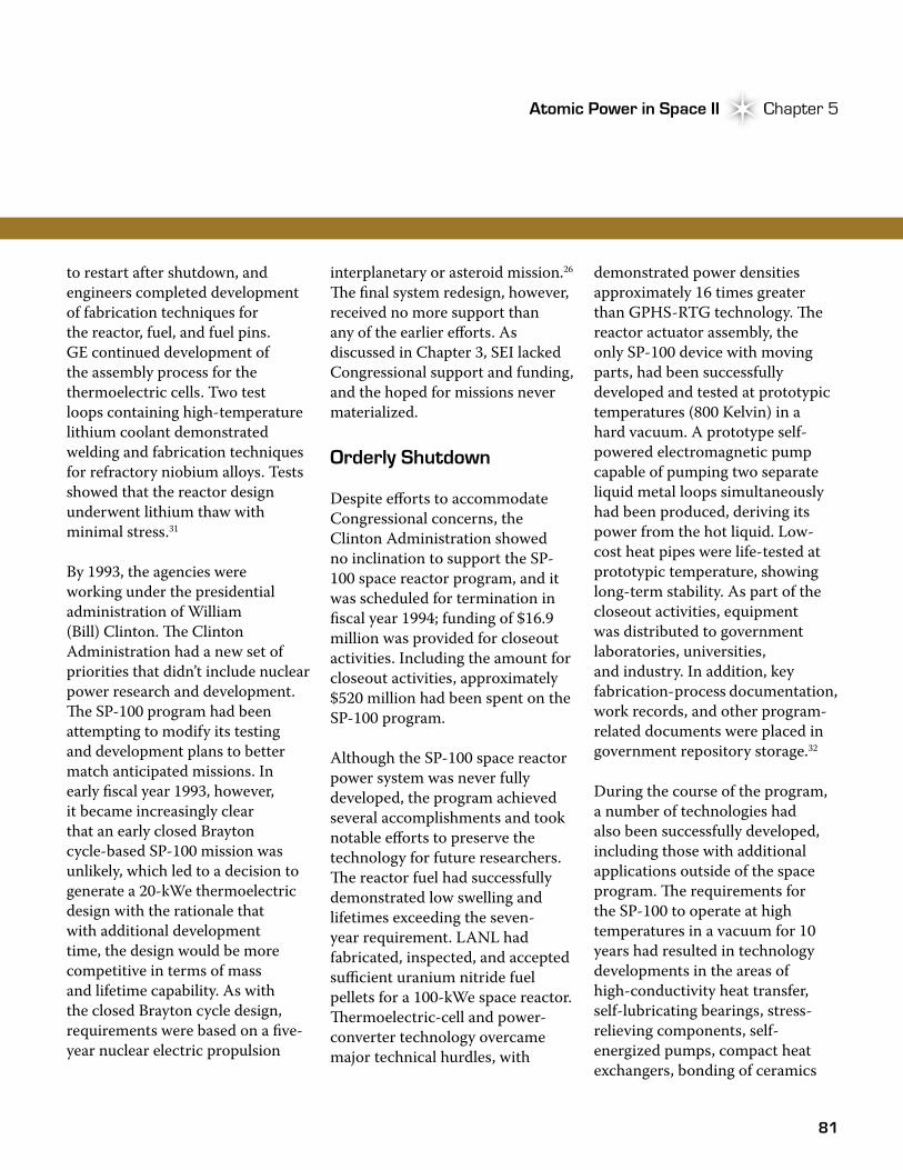
81
Atomic Power in Space II Chapter 5Atomic Power in Space II Chapter 5
to restart after shutdown, and engineers completed development of fabrication techniques for the reactor, fuel, and fuel pins. GE continued development of the assembly process for the thermoelectric cells. Two test loops containing high-temperature lithium coolant demonstrated welding and fabrication techniques for refractory niobium alloys. Tests showed that the reactor design underwent lithium thaw with minimal stress.31
By 1993, the agencies were working under the presidential administration of William (Bill) Clinton. �e Clinton Administration had a new set of priorities that didn’t include nuclear power research and development. �e SP-100 program had been attempting to modify its testing and development plans to better match anticipated missions. In early fiscal year 1993, however, it became increasingly clear that an early closed Brayton cycle-based SP-100 mission was unlikely, which led to a decision to generate a 20-kWe thermoelectric design with the rationale that with additional development time, the design would be more competitive in terms of mass and lifetime capability. As with the closed Brayton cycle design, requirements were based on a five-year nuclear electric propulsion
interplanetary or asteroid mission.26 �e final system redesign, however, received no more support than any of the earlier efforts. As discussed in Chapter 3, SEI lacked Congressional support and funding, and the hoped for missions never materialized.
Orderly Shutdown
Despite efforts to accommodate Congressional concerns, the Clinton Administration showed no inclination to support the SP-100 space reactor program, and it was scheduled for termination in fiscal year 1994; funding of $16.9 million was provided for closeout activities. Including the amount for closeout activities, approximately $520 million had been spent on the SP-100 program.
Although the SP-100 space reactor power system was never fully developed, the program achieved several accomplishments and took notable efforts to preserve the technology for future researchers. �e reactor fuel had successfully demonstrated low swelling and lifetimes exceeding the seven-year requirement. LANL had fabricated, inspected, and accepted sufficient uranium nitride fuel pellets for a 100-kWe space reactor. �ermoelectric-cell and power-converter technology overcame major technical hurdles, with
demonstrated power densities approximately 16 times greater than GPHS-RTG technology. �e reactor actuator assembly, the only SP-100 device with moving parts, had been successfully developed and tested at prototypic temperatures (800 Kelvin) in a hard vacuum. A prototype self-powered electromagnetic pump capable of pumping two separate liquid metal loops simultaneously had been produced, deriving its power from the hot liquid. Low-cost heat pipes were life-tested at prototypic temperature, showing long-term stability. As part of the closeout activities, equipment was distributed to government laboratories, universities, and industry. In addition, key fabrication-process documentation, work records, and other program-related documents were placed in government repository storage.32
During the course of the program, a number of technologies had also been successfully developed, including those with additional applications outside of the space program. �e requirements for the SP-100 to operate at high temperatures in a vacuum for 10 years had resulted in technology developments in the areas of high-conductivity heat transfer, self-lubricating bearings, stress-relieving components, self-energized pumps, compact heat exchangers, bonding of ceramics

82
The SP-100 Program 100-KWe Space ReactorThe SP-100 Program
to metals, high-temperature electric coils, electrical insulators, thermometers, high-temperature motors, and generators.32
Because many of these components had potential commercial uses, with permission from DOE, the SP-100 project office at JPL began an aggressive project late in 1993 to find commercial applications for fabrication processes, devices, and components developed during the SP-100 program.
Over 100 companies expressed interest in the technology transfer prospects that included self-lubricating ball bearings for the space shuttle, electric motors for aircraft activators, and the use
of the gas-separator concept to remove gases from liquids in the manufacture of syrup for soft drinks.32, 33
Looking Back
With the end of the SP-100 program, the latest chapter in U.S. space reactor history came to a close. Although the proposed reactor system was never fully developed, many advancements were made in space reactor system technology and other supporting areas. �e vision of repeating the success of the SNAP-10A launch 30 years earlier finally faded, succumbing to the weight of inadequate funding, lack of missions, and a changing political landscape that questioned the very need for ongoing nuclear research and development.
�e tentacles of change reached far beyond the SP-100 program. �e EBR-II, one of the nation’s
During the course of the program, a number of technologies had also been successfully developed, including those with additional applications outside of the space program.
Experimental Breeder Reactor-II at Idaho National Laboratory. (Photo: Idaho National Laboratory Flickr)
83
Atomic Power in Space II Chapter 5Atomic Power in Space II Chapter 5
only fast-reactor test facilities, was shut down in 1994. �e ZPPR facility was shut down in 199038 and the Hanford FFTF was shut down in 1992 (the last fuel was removed from the reactor years later, in 2008). Other facilities, such as the Plutonium Recycle and Test Reactor Complex, would eventually succumb to the massive cleanup effort conducted under the DOE Environmental Management Program. For some, such shutdowns and dismantlement may have signified progress relative to the nation’s Cold War cleanup legacy. For others, the shutdowns meant the loss of a livelihood. Regardless, the nation lost a piece of its nuclear heritage and a significant amount of its nuclear infrastructure.