Embed Size (px)
Citation preview

13Ó PHILIPS TECHNICAL REVIEW VOL. 14, No. 5
'THE IMPULSE-GOVERNED OSCILLATOR, A SYSTEM FORFREQUENCY STABILIZATION
by E. H. HUGENHOLTZ *).
I The introduction of the quartz crystal in radio tçchnique 25 years ago solved the problemof constructing an oscillator with constant frequency. A drawback of the crystal, however,is that it is suitable for only one frequency so that transmitters which are to operate at differentfrequencies, require several crystals with the present-day circuit designs, and:in a transmiueroperating with a continuously variable frequency the crystal cannot be used at all.
This article describes a method by which, with only one crystal, signals can be generàtedwith a series of very stable frequencies, and, if required, a signal can be obtained with. acontinuously variable frequency' which is lle~erthelessvery stable.
Introduetion
Two important problems have arisen in relationto the frequency of the oscillators now used in radiotransmitters and receivers because of increasedtraffic and' speed. These are:a) it must be possible to adjust the frequency very
accurately;b) there must be absolute stability of the frequency
under changing working conditions, for instance,the ambient temperature or the supply voltagesof the valves.In addition, it is sometimes necessary to change
the frequency at short notice.In transmitters operating at one, constant, fre-
'quency and in which frequency changes are com-paratively rare, as is the case in broadcasting trans-mitters, a quartz crystal "], usually mounted in athermostatically controlled container, is generallyused. ,Quartz crystals can also be used in trans-mitters which use several frequencies for broad-casting, which can be selected as the necessity arises.In that case there must be a crystal for each fre-quency, and the thermostatically controlled con-tainer in which the crystals 'are mounted must belarge. A drawback of this system is that it takes afairly long time before the required temperature isreached, which may lead to difficulties in mobileinstallations. The cost of a great number of quartzcrystals is another deterrent., If the frequency of an oscillator must be con-tinuously variable in a certain range, an oscillatorycircuit with a variable capacitor is generally used.Various measures are then taken to ensure thatthe oscillator frequency depends as little as possibleupon the operating conditions. Compensation isapplied for frequency variations caused by tempera-
*) N.V. Philips' Telecommunicatie Industrie, Hilversum.~) See, for instance, J. C.B.Missel, Piezo-electricmaterials,
Philips techno Rev. 11, 145-150, 1949.
621.396.615.12 :621.316.726
ture fluctuations, and considerable accuracy ofadjustment can be achieved by dividing the requiredfrequency range into a number of smaller rangeswhich can be selected by changing coils. This oftenmakes the installation fairly complicated, however,and the usual requirements of direct-reading dialscannot be easily met. Moreover, the frequencystability that can be obtained is always less thanthat which can be achieved with a quartz crystal.If the frequency range must be continuously
variable only in a limited range, a high degree ofstability can be achieved with the type of circuit
Fig. 1. Fundamental diagram of a system for obtaining analternating voltage whose frequency can be continuouslyvaried within a limited range and possesses eonsiderablestability.KO = crystal-controlled oscillator; VO = oscillator of whichthe (continuously variable) frequency is much lower thanthat of KO; M = mixer; F = filter.
of which the principle is given in jig. 1. If, forexample, a voltage is required having a frequencythat ~an he varied between 1 and 1.1 Mc/s, it maybe obtained by supplying two voltages to a mixervalve M. One ?f these is supplied by a crystal-controlled oscillator KO, having a frequency of,for example, 0.8Mc/s, and the other by an oscillatorVO, of which the frequency is continuously variablewithin a 'range of 0.2_to0.3 Mc/s. The mixer supplies,amongst others, a voltage at a frequency which isequal to the sum of the two oscillator frequencies

NOVEMBER 1952 IMPULSE-GOVERNED OSCILLATOR - 131
and which can be varied between 1 and 1.1 Mc/s.As the frequency changer also supplies voltages withfrequencies which are not required, the voltagerequired will have to be supplied via a filter F.
As the oscillator VO operates at a comparativelylow frequency, a greater frequency stability can beobtained than by using an oscillator having afrequency that is continuously variable between1 and 1.1 Mc/s. It will be clear, however, that thisadvantage is no longer present when a voltage isrequired with a cdntinuously variable frequencyover an extensive range, for example, from 1 to10 Mc/s. This range could be achieved, of course, ifa large number of crystal oscillators were availablewith frequencies of, for example, 0,8 Mc/s, 0.9 Mc/s,1.0 Mc/s, 1.1 Mc/s etc., and ,in addition, an oscillatorwith a continuously variable frequency in a limitedrange, for instance, from 0.2 to 0.3 Mc/s. Thissolution is obviously not very attractive.The system described becomes impracticable at
higher frequencies when the ratio between thecrystal frequency and the frequency of the contin-uously 'variable óscillator will generally be large.This means that the relative distance between therequired frequency and the unwanted crystal fre-quency is. small, so that high requirements are im-posed on the filter Fwhich is intended, in tbe firstplace, to suppress the crystal frequency (and alsothe image frequency).'
Another possibility is to use one crystal oscillatorwith a frequency of, for example, 0,1 Mc/s and toobtain from it, by means of frequency multiplication,voltages of which the frequency is a whole multipleof the oscillator frequency. Frequency multiplica-tion may be obtained, for example, by means of aso-called impulse generator, i.e., a generator whichdoes not produce ~ sinusoidal alternating voltage,but a series of periodic voltage impulses. Such animpulse generator can be synchronized with thecrystal oscillator, so that the frequency of the im-pulses is equal to the frequency of the oscillatorvoltage. It is possible to obtain from the periodicvoltage impulses, by means of filters, alternatingvoltages of which the frequency is a whole multipleof the impulse frequency. This system, however,requires a complicated set of filters, the very highselectivity requirements of which can hardly berealized, particularly if high ordinals' of harmonicsare required.The following will describe another solution of
this problem, namely the Impulse-Governed_ Oscillator (IGO). This method' enables thee fre-quency of an oscillator to be adjusted, quite simply,to a large number of values with the same degree of
accuracy as would be achieved if a quartz crystalwere used for each of these frequencies.
The principle ofthe IGO is frequency stabili-zation by means of an automatic controlsystem (often referred to as the "automaticmonitor system"), which will be explained first inmore detail.
Stabilizing an oscillator frequency by means of anautomatic control system ("automatic monitorsystem"~
Fig. 2 shows the principle of this method of fre-quency control. The stabilized oscillator SO suppliesa signalof frequency il which is applied to the mixerM. A signalof another frequency, i2' supplied by anoscillator KO, and of which the frequency is stabili-zed by means of a quartz crystal, is simultaneously
Fig. 2. Fundamental diagram of the "automatic monitorsystem" for frequency stabilization. SO= controlled oscillator,1(0 = crystal-controlled oscillator, Af = mixer, V= amplifier,D = discriminator (frequency detector), FR = frequèncycontrol device.
supplied to the mixer. The mixer M supplies, amongstothers, an alternating voltage of frequency lil-i21 andthis voltage is amplified in the amplifier V,after whichit is fed to the discriminator (frequency detector) D.The circuits of the discriminator are tuned to acertain frequency id. The discriminator supplies adirect voltage er which is either positive or negativeaccording to whether lil-i21 is greater or smallerthan id. If IA-i21 is equal to id, then er = O.The direct voltage er, which is called the controlvol tag e, is fed to a control device FR which enablesthe oscillator frequency to be varied. This controldevice may consist, for example, of a capacitorwhose shaft is driven by a small electric motor, orit may consist of 'a direct control de~ice, forexample a reactance valve 2). The arrangement ofFR may be such that, when er is positive, the fre-quency of SO is reduced and vice versa. Thus, FRalways influences the frequency of SO to such an
2) See, for example, Th. J. Weijers, Frequency modulation,Philips techno Rev. 8, 42-50, 1946. .

':',
PHILIPS TECHNICAL REVIE'V VOL. 14., No. 5132
extent, that If1-f21 is approximately equal to ]d.The frequency f1 of the oscillator SO is, therefore,approximately stabilized to the value f2-fd or f2+fd,depending onf2 being larger or smaller thanf1' It iseasy to see, however, that this frequency controlwill never achieve that If1-121 is exactly the sameas fd, for in that case the control voltage er wouldbe zero.If the discriminator D supplies a control voltage
er of a volt per kcfs deviationbetween If1-121andfd,and if tbe detuning to which the oscillator SO issubjected by the control device FR is equal tob kcfs per volt control voltage, each deviation of f1from the required value fd=fd would by reducedhy a factor a·b 3). _ .
The discriminator D may be constructed in thesame way as the frequency detectors used in F.M.
Fig. 3. Fundamental diagram of a system for frequency control.lfD is a comparative discriminator, a control with proportionalaction is obtained; if D is a phase discriminator, frequencycontrol with integral action is obtained. The significanee ofthe other letters is given in figs 1 and 2.
receivers 2). The frequency stability of tbe oscillatorSO is determined, on the one band, by that of thecrystal oscillator KO and, on the other hand, bythe stability of the discriminator D. Generallyspeaking, fd is chosen much lower than Rand j;,so that the absolute value of the residual deviationbetween IR-121 andfd is small in relation to fr Tbeerror in the frequency of SO, caused by the factthat there will always remain a control voltage enhowever, usually considerably exceeds the sum ofthe errors of KO and D.
The same objection is found in another controlsystem of which the principle is shown in jig. 3. Inthis system the 'voltages supplied by SO and KOare applied to a so-called comparative discrimi-nat 0 r D, which is a circuit supplying a controlvoltage er of which the amplitude and sign dependupon the magnitude and the sign of the frequencydifference hetween SO· and KO 4). Here too, thecontrol voltage is supplied via a low-pass filter F
3) H. J. Ro osdorp, On the regulation of industrial processes,.Philips techno Rev. 12, 221-217, 1951. This concerns aso-called frequency control with proportional action.
4) In order to make a distinction from this, a discriminator,as incorporated in the diagram of fig. 2 and to which onlyone alternating voltage is applied, is called an absolutediscriminator.
to the frequency control device FR, which influèneesthe frequency of SO. It will be clear that in thiscase, too, equality of the SO and KO frequenciescannot be obtained.It has been explained in the article quoted in
footnote 3) that this disadvantage is inherent inevery automatic control system with proportionalaction. With "the aid of a control systeem withintegral action, however, the deviation of f1with respect to 12 can be reduced to nothing. Tobring about such a control, Jl) in fig. 3 must hereplaced by a so-called phase discriminator 5).This refers to a circuit which supplies a control
. voltage er of which the amplitude and sign dependupon the magnitude and sign of the. ph ase differencebetween the voltages supplied by SO and KO (thusthe frequencies f1 and f2 are assumed to be equal inthis case). As the frequency is the derivative of tbe .phase 2), this is a control with integral action forthe frequency.If the frequencies f1 and f2 are not equal, D will
supply an alternating voltage of which the frequencyis equal to liI-f21. If this frequency is lower thanthe cut-off frequency of the low-pass-filter F, thisalternating voltage is supplied to the frequency con-trol device FR, which affects the frequency of SO.Provided the inertia of FR is not too large, thefrequency of SO will then vary periodically. Whenthe value f2 is passed, D supplies 'a direct voltage,which influences the frequency of SO, via F andFR, to such an extent, that this synchronizationcondition between SO and KO is maintained. Inthat case, there is no longer any frequency differencebetween SO and KO, hut merely a phase shift,If the frequency of SO still differs so much from
that of KO thai the difference is larger than thecut-off frequency of F, the frequency 'stabilizationof SO will be non-effective. The "collectingzone", i.e., the frequency range in which the fre-quency of SO should be before stabilization heginsto act, is, therefore, determined by the cut-offfrequency of the filter F. The so-called "holdingzone" is generally understood to he the frequencyrange within which SO can he detuned (once syn-chronization has taken place) before synchron-ism is lost. This frequency range js determined bythe range in which FR can correct the frequencyof SO and by the voltage supplied by the phasediscriminator D, at a certain phase shift betweentbe voltages supplied by SO and KO. Generallyspeaking, the "holding zone" is larger than the"collecting zone"
ó) Also discussed in Philips techno Rev. 13, 316 (fig. 4), 1952(No. 11).

NOVEMBER 1952 IMPULSE-GOVERNED OSCILLATOR - 133
Fig. 4 is the fundamental diagram of a systemfor frequency control with integral action, wherebythe frequency f1 of the controlled oscillator SO canhe varied over a limited range. This frequency isnot stabilized to the frequency f2 of KO, but to a
Fig. 4. Fundamental diagram of a frequency control systemwith integral action, in which there is a difference betweenthe frequencies of the stabilized oscillator SO and the crystal-controlled oscillator KO, determined by the frequency of theoscillator with variable frequency VOo FD = phase discrimi-nator. The significanee of the other letters is as given infigs 1 and 2.
value which differs by a certain amount from f2.To achieve this, the voltages supplied by SO and KOare again supplied to the mixer M,which will supplya voltage having a frequency Ifc:f21. This voltageis applied to a phase discriminator FD, togetherwith the voltage from an oscillator VO of which
f1 will be corrected by the same amount. If f3 jschosen much lower than f1 (in other words, if f1differs but little from f2)' a much larger stabilitycan be obtained, than if SO itself were to beconstructed as an oscillator with variable frequency.By making a change in the scheme shown in the
diagram in fig. 3, arrangements can be made where-by the oscillator SO is synchronized to a harmonicof the voltage of the crystal oscillator KO, so that'the frequency of SO is exactly the same as a wholemultiple of the frequency of KO.An impulse generator is used for this purpose, so
that such a circuit is known as an Impulse-GovernedOscillator (IGO) 6).
The Impulse-Governed Oscillator (IGO)
The principle of the IGO is explained with the aidof the diagram of fig. 5. The valve BI with theoscillatory circuit L1-C1, forms an oscillator(Hartley circuit). The frequency ofthe voltage sup- 'plied by this oscillator is influenced by the reactancevalve B2 as well as by L1 and Cl" An alternatingvoltage with the oscillator frequency which lagsin phase' about 90° with respect to the alternatiflganode voltage, is supplied to the grid of this valvevia the phase-shifting network R2-C2• This causes theanode current of B2 to be about 90° lagging in phasewith respect to the anode voltage, and the impedan-ce of this valve, between anode and cathode, will
69515
~----------------------------------~-------------------+~Fig. 5. Circuit diagram of an impulse-governed oscillator. Bl = oscillator valve, B2 =reactance valve, B3 = impulse mixer valve.
the frequency fa can be varied within a certainfrequency range. The voltage er supplied by FD isfed via the low-pass filter F to the frequency controldevice FR, thus influencing the frequency of theoscillator SO. The latter frequency will now bestabilized so that Ifc~f21 =fa, thus f1 will be equalto f2 + fa or f2 -f3. If the frequency of VO is varied,
have a reactive character. The extent of the1
equivalent reactance depends, amongst other things,upon the mutual conductance ofthe valve and hencemay be influenced by the grid voltage of B2•
R) • See also H. B. R. Boosman and E. H. Hugènholtz,Frequency control in transmitters, Communication News 9,21-32, 1947.

134 . PHILIPS TECHNICAL REVIEW VOL. 14, No. 5
The alternating voltage supplied by the oscillatoris fed to a so-called impulse mixer valve, the pentodeBa' In this valve, such a la,rge positive voltage isapplied to the cathode with respect to the first grid,that no anode current flows in the valve. The firstgrid is supplied with a series of periodic positive.voltage impulses, obtained' from an impulse gener-ator which will be described later. The peak volt-age of these impulses has such a high value that,during each impulse, anode current flows for avery short time in Ba. The voltage supplied bythe oscillator Bl is applied to the third grid of Ba.
The operation of a circuit in accordance withfig. 5 will be explained with the aid of fig. 6. Thisdiagram shows the alternaring voltage Vg3 suppliedbythe oscillator and the voltage impulses Vgl appliedto the first grid of Ba. If the frequency of Vga isa whole multiple of that of Vgl, the anode currentimpulses will always occur at the same phasing of V~a'. ~
69516
\ IIfQ ~IIL......Jj.I----~ -------lJL----lj1--
Fig. 6. Graphs explaining the operation of the IGD. Theoscillator voltage Vg3 at the third grid (c) and the impulsevoltage Vgl (d) at the first grid of B3 are presented as functionsof time (see fig. 5). The anode current impulses, for the casethat the relative phasing of Vgl and Vg~, is as indicated byI and II (a and b resp.), are also indicated as functions of time.
If this is the position indicated in fig. 6c by I, theamplitude of the anode current impulses will beat its highest, in 11 it is at its lowest. Thesecurrent impulses cause a periodical charging of thecapacitor Ca (fig. 5). The capacitance of this is solarge that a practically ripple-free direct voltageoccurs across Ca, and the amplitude of this dependsupon the relative phasing of Vgl and Vg3• Thisvoltage is applied via the low-pass-filter F to thegrid of the reactance valve B2• The average valueofthis control voltage is obtained when the impulsesat the first grid occur at exactly that moment whenthe alternating voltage Vga pass.es through zero.Thus, a very small deviation in this setting causes
a larger or smaller control voltage to occur. Thisdirect voltage, in turn, influences the frequency ofthe oscillator, through the reactance valve B2• Ifthe tuning of this oscillator is changed by an amountwhich is not too large, the phasing of Vgawill changewith respect to that of Vgl, causing the controlvoltage to he altered, and the variation in the oscil-lator frequency is compensated. Thus, the os~illatorfrequency remains equal to a whole multiple of thefrequency of the impulses' applied to the first grid.If this synchronism has not occurred at the mo-
ment of switching on, there will be a periodic varia-tion of the voltage produced across Ca, in otherwords an alternating voltage is obtained 7) by which,if the frequency is lower than the cut-o'ff frequencyof F, the oscillator voltage is frequency-modulated.If, during this modulation, the óscillator' frequencypasses a value which is equal to a whole multipleof the impulse frequency, the oscillator frequency willremain at this value. Theoretically, it should be ofno account whether the relative phasing of Vgl and.Vga adjusts itself in such a way that the impulse liesupon one or the other flank of the sinusoidal curve .According to the direction of the control of B2' theadjustment upon one of the flanks is, however,unstable and that upon the other is stable.
The low-pass filter F suppresses voltages at theimpulse frequency ör multiples of it. This preventsthe oscillator from being subjected to phase modula-tion at these frequencies.
When compiling fig. 6, the oscillator frequencywas taken to be equal to twice the impulse frequency.It will be clear that synchronization, as describedabove, mayalso occur when the ratio between thesenumhers is' a larger integer. The maximum valueof this number, as will be obvious from fig. 6, isdependent upon the duration of the impulses. For,if the frequency of the oscillator voltage is so highthat the duration of one period is equal to theduration of the impulses, the time integral of theanode current impulses "will be independent of themutual phase position of Vgl and Vga, so that, witha phase shift of the oscillator voltage with respect tothe voltage impulses, no alteration occurs in the con-trol voltage 8). For still higher frequencies, a controleffect does again occur, reaching a maximum whenthe ratio of the impulse duration to the duration
7) This effect is analogous to the stroboscopic effect in lightwhich occurs, for example, when a rotating wheel withspokes is illuminated by light flashes, whereby the "spokefrequency" deviates a little from a whole multiple of theflash frequency. The wheel is then seen to rotate slowlyeither clockwise or anti-clockwise.
8) A similar problem is deseribed by J. M. L. Janssen,Philips techno Rev. 12, 52-59, 1950 (No. 2), in particularon pages 57 and 58,
NOVEMBER 1952 IMPULSE-GOVERNED OSCILLATOR 135
of one period of the oseillator voltage reaehes avalue of 3/2, When the ratio is 2, there is again nocontrol effect, etc. Fig. 7 illustrates, on a relativescale, the control voltage as a function of the above-mentioned ratio: Here, tbe control volt-age is thevariation of the voltage across the capacitor C3 ata change in phase of 1800 of Vg3 with resp~ct toVgl' In order to ensure the correct operation of anIGO, the duration ofthe impulses should preferably
69511
4 n
Fig. 7. Variation Llcr of the control voltage at a phase changeof 1800 of the oscillator voltage as a function of the ratio n ofthe duration of the impulse to that of a cycle of the oscillatorvoltage.
not be larger than half a period of the oscillatorvoltage. To facilitate the synchron.ization of anoscillator whose ,frequency is much higher than theimpulse frequency, it will therefore be necessary tomake the impulse duration as short as possible.In practice, this is limited by the fact that, at veryshort impulses, the average value of the currentthrough the valve B3 (see fig. 5) becomes extremelysmall. Usually, however, another practical limita-tion occurs at even lower oscillator frequencies. If,for example, it is, required to synchronize the oscil-lator voltage with the 200th harmonic of the im-pulse voltage, this means that a deviation of onlyl/2% in the proper frequency of the oscillator givesa neighbouring harmonic of the impulse voltage.Hence, high requirements are already imposed onthe frequenèy stabilization of the controlled oscil-lator itself, in order to maintain the synchronizationat the required frequency. For this reason, it appearsto be impracticable to make Impulse GovernedOscillators which are synchronized at higherharmonics of the pulse voltage than the 200th.
In an IGO, a distinction can again be madebetween a collecting and a holding zone, with re-gard to the frequency range in which the frequencystabilization is operative. The former frequencyrange is determined mainly by the cut-off frequencyoft~e filter F (fig. 5). For, before the synchronizationof the oscillator voltage occurs, the mixer valve B3supplies an alternating voltage and only ,when thefrequency of this voltage is so small that it is passed
by the filter F, is it possible for frequency stabiliza-tion to operate. The "holding" zone is determinedby the control voltage, supplied by B3' when, oncesynchronization has occurred, the oscillator voltageis subjected to a certain phase shift. Moreover, itdepends on the frequency range in which the oscil-lator can be detuned by the reactance valve. Àsthere is a possibility that the oscillator voltage issynchronized to a wrong harmónic of the impulsevoltage, it is desirable not to make the latter fre-quency range much larger than the frequency inter-val between two harmonics. By making provisionthat the holding zone slightly exceeds this interval,it may be achieved that with the (apparently)continuous detuning ofthe oscillator, the frequency,jumps steadily from one harmonic to .the next.The construction can then be made in such a waythat, by means of a pawl setting, the correctharmonic is selected.
For most applications oscillators must supply apure sinusoidal voltage with the least possibleamplitude and frequency modulation. Deviationsfrom the sine w~ve may be mainly due tó twocauses, in an IGO. These are:a) the filter F (see fig. 5) does not sufficiently
suppress voltages with the impulse frequencyand, possibly, harmonics of it; this causes fre-quency moduiation of the oscillator;
b) harmonics of the impulse voltage produce analternating voltage in the oscillator circuit viathe mixer valve B3 (see fig. 5); when a multigridmixer valve is used, this can occur only viathe interelectrode capacitances.Practice has shown that in the case of frequencies
which are not too high, it is comparatively easy toensure that the voltages with unwanted frequenciesare at a level of about -80 dB with respect to theoscillator voltage, mainly because the power of theimpulse harmonics is small compared with the out-put of the oscillator. This level is practically alwayssufficiently low.
It has been shown that an IGO is a circuit fedwith a periodic series of voltage impulses, and th:atit supplies an alternating voltage of which the fre-quency is equal to that of one of the ha~monics' ofthe voltage impulses. The IGO is, therefore, to acertain extent similar to a filter which passes such a'narrow frequency band that only the requiredharmonic is passed. The frequency to which this fic-titious filter has been adjusted may be changedsim-ply by varying the tuning ofthe oscillator, whereasthe width of the frequency band is determined by the
-;

·'
136 PHILIPS TECHNICAL REVIEW .VOL. H., No. 5
low-pass filter F. For instance, when an interferingalternating voltage is present on the first grid of thevalve B3' in addition to the voltage impulses, andthe frequency of this interfering voltage differs verylittle from that of the required harmonic of theimpulse frequency, an alternating voltage willoriginate in Ba of which the frequency is equal tothe difference of the frequencies of the oscillatorvoltage and the interfering voltage. It dependsentirely upon the filter F, whether this voltage ispassed to the grid of the reactance .valve or not.'If it is, the oscillator voltage will.be frequency mo-dulated. If the filter F does not pass, the interferingvoltage, the oscillator will not be affected by it.. It is of importance, in this respect, to choose thecut-off frequency of the filter F as low as possible(unless it is desired to modulate the oscillator fre-quency). In this case the collecting zone will becomesmall and, in practice, a oompromise will have tobe accepted.
A circuit like the one depicted in fig. 5 is a form of inversefeedback. If a phase shift occurs in the circuit through whichthe control voltage of the mixer valve B3 is supplied to thegrid of the reactance valve, there is a possibility that thecircuit becomes unstable in this sense that the oscillator doesnot operate at a constant frequency, but is subjected toperiodic frequency changes, thus is frequeney modulated. Thisphenomenon is almost identical to what happens in othercircuits with inverse feedback. There is, however, one funda-mental difference in the stability condition. An altcrnatingvoltagê applied to the grid of the reactance valve B2 gives riseto frequency modulation, whereas the control voltage sup'plied by the frequency changer B3 varies through ph ase shiftsof the oscillator voltage.There is a phase shift of 90° U) betweena phase change (displacement) and frequency change thatcorresponds with it. 'Vhereas in an "ordinary" amplifier withinverse feedback, a phase shift of 180° is necessary at thecritical frequency ID) to cause instability, here it is merely 90°.In addition, the phase change (displacement) which helongsto a certain frequency change is inverselyproportional to ~hemodnlation frequency. This means that the higher the criticalfrequency can he adjusted, the smaller will be the risk ofinstability in an IGO.
In the example so far reviewed it is assumed that an oscil-lator is synchronized by an impulse generator. It is, however,also possible to synchronize an impulse generator with anoscillator of which the frequency has been stabilized by acrystal. This may be done by feeding the control voltagesupplied by the mixer valve to a control system whichinfluences the frequency of the impulse oscillator. If thefrequency of the impulse generator is lower than that of thecrystal oscillator, frequency division will take place in whichthe frequency ratio is the same as the multiplication factorin the previous case.
9) See the article mentioned under 2), p. 44.lU) See B. D. H. Tellegen, Inverse feed-hack, Philips teclm.
Rev. 2, 289-294-, 1937.
'Vhen an impulse generator is phase modulated, an IGOsynchronized to the nth harmonic of it will also be subjectedto an n times larger phase modulation, provided the timeconstant of the control circuit is small enough to pass thehighest modnlation frequency without much phase shift.Because of the high value of n, which eàn be reached quiteeasily in this case, an extensive phase shift can be obtainedwithout much trouble. Thus, a "phase mod~llationin a narrow-er sense" 9) is obtained. In order to get the form of the phasemodulation which is usually referred to as frequency modnla-tion, the modulation voltage must be supplied via a networkwhich will correct the frequency characteristic in this sensethat the "phase swing" becomes inversely proportional to thefrequency of the modulating voltage.
Practical construction of the impluse generator
For most purposes in which an IGO i~ used, theimpulse frequency must comply with high demands
_ of accuracy and stability. The frequency must havea very accurate' value, for example, exactly 100 kc/s, 'so that the IGO is always synchronized to a fre-quency which is a whole multiple of this value. Inview of the fact that, in practice, synchronizationto a frequency which is 200 times higher than thatof the impulse generator is possible, an IGO maybe contructed with a frequency up to 20 Mc/s. Asit is preferable for the impulse duration not to helonger than the duration of a half cycle of the volt-age produced by the IGO, the maximum impulsetime is about 1/4.0 [Lsec.
Because of the considerable stability required, animpulse generator is always used, in practice, inwhich the impulses supplied are synchronized, in theirturn, with a sinusoidal voltage. The latter is suppliedby an oscillator of which the frequency is stabilizedby a quartz crystal, which may be placed in a ther-mostatically controlled container. Fig. 8 givesdetails of a circuit which might be used for thispurpose. This is based upon the principle of theringing oscillator. The hexode section of thetriode-hexode BI fulfils this function. By a suitableselection of the grid capacitor CI,and the grid leakRI' intermittent oscillation is obtained 11). The set-ting may be adjusted so that the oscillating isinterrupted after a few periods and does not startagain until the capacitor Cl' w}llch is charged be-cause of the flowing of a grid current, has been suf-ficiently discharged via the resistor RI' Thus, aseries of periodic, damped, oscillations occurs in theanode circuit of the hexode section, as is indicatedin the lower part of fig. 8. Its repetition frequencyis largely determined by the values of Cl and RI'
11) See J. van Slooten, The functioning of triode oscillatorswith grid condenser and grid resistance, Philips technoRev. 7, 40-45, 1942, and Stability and instability in triodeoscillators, Philips techno Rev. 7, 171-177, 1942.

NOVEMBER 1952 IMPULSE-GOVERNED OSCILLATOR
The triode section of B1 is used as an oscillatorof 'vhich the frequency is stabilized by a quartzcrystal. The oscillator voltage is applied to the thirdgrid of the hexode section, When the repetition fre-quency of the damped oscillations is approximatelythe same as the frequency of the crystal oscillator,synchronization occurs, and these frequencies willbecome ide~tical. The damped oscillations obtained
been constructed in accordance with the 'principlesdescribed here, The chassis also houses the mixervalve (B3 in fig. 5). The impulse duration whichcan be obtained with this device is 1/14. (J-sec.Pro-ceeding from the condition that the duration ofthe impulses may, as a maximum, be equal to theduration of a half cycle of the voltage generated bythe lGO, it will be clear that this may he used
~------------------------_.--~----------~--~+
o v
Fig. 8. Diagram of an impulse generator. The triode section of the valve BI acts as acrystal-controlled oscillator; the hcxode section of this valve forms a ringing oscillator. Theimpulse duration is shortened by means of the valve B2• The lower part of the illustrationshows the anode currents as functions of the time.
are now applied to the grid of the valve B2' which is_negatively biased to such an extent that anodecurrent flows only during part of the first halfcycle of each of the series of damped oscillations.(For, the amplitude is largest in the first half cycle).Thus, short current impulses occur in the anodecircuit of B2• The coil L1 has been incorporated inthis circuit and with the valve and wiring capaci-tances it forms an oscillatory circuit. This circuitis periodically excited by the anode current impulses.A second coil, L2' to which a rectifier has been con-nected, has heen coupled to the first coil L1' so thatthis oscillatory circuit can pass on only half anoscillation every time it is excited, thus ensuringvoltage impulses of very short dur~tion. Thesepulses serve 1:0 synchronize the actual, adjustableoscillator (see fig. 5).
Synchronization of the intermittently oscillatingoscillator with the crystal oscillator mayalso he doneso that frequency division takes place. The crystaloscillator may oscillate, for example, at a frequencyof 100 kc/s, while the periodic oscillating occurs ata frequency of 50 kc/so ..Fig. 9 illustrates an impulsegenerator which has
to synchronize an oscillator with a maximum fre-quency of7 Nic]«. By adding a third valve to a set-upas shown in fig. 8, connected in the same way as B2'it has shown possible, in practice, to obtain an im-pulse duration of 1/180 (J-s~c,so that the synchroni-zation of an oscillator with a frequency of 90 Mc/sis possible.
Decade tuning
It has heen explained that an lGO can he syn-chronized to a frequency which is equal to anymultiple of the frequency of an impulse generator,which itself can be synchronized by a crystaloscillator. This makes the lGO admirably suited foruse in transmitters, receivers and other apparatus inwhich so-called decade tuning is used, The principleof this system 'has already been explained with theaid of fig. 1. An alternating voltage with a frequency,which can be varied over an extensive range, isobtained by supplying two voltages to a 'mixervalve. One of these voltages is adjustable to frequen-cies which are a whole multiple of, for example,100 kc/so The frequency of the other oscillator iscontinuously variable in a range of 100 kc/s, for
137
138 PHILIPS TECHNICAL REVIEW VOL. 14, No. 5
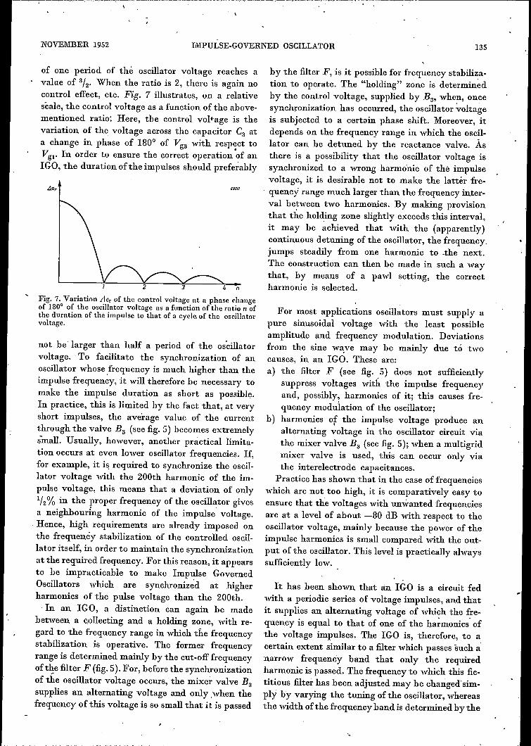
Fig. 9. Crystal-controlled impulse generator and impulse mixer valve (fig. 11: IC and IM)from the aircraft transmitter SVZ lOl.
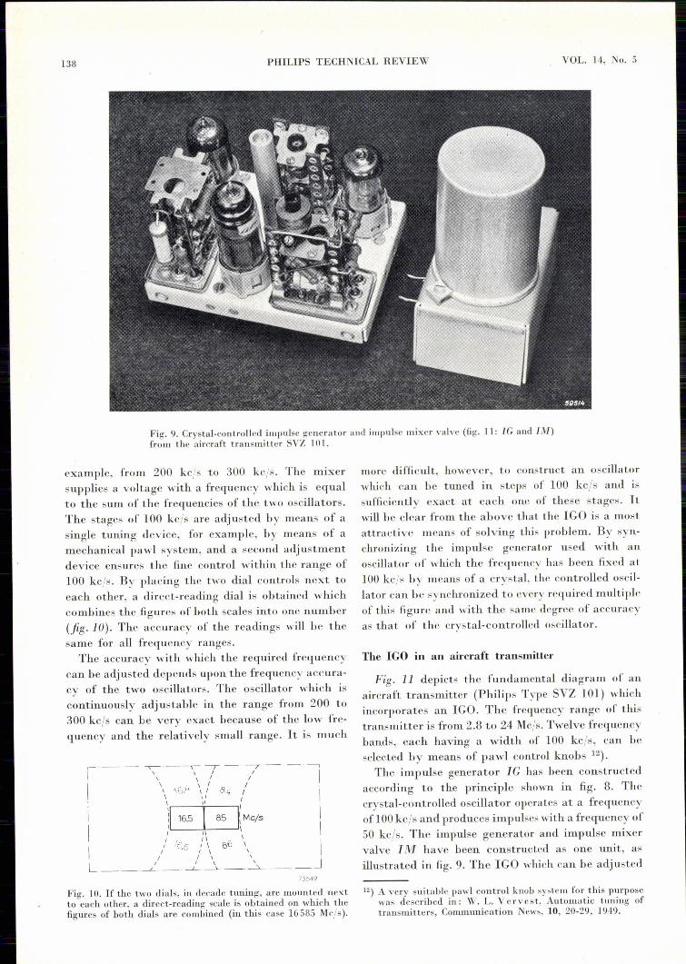
example, from 200 kc/s to 300 kc/s. The mrxersupplies a voltage with a frequency which is equalto the sum of the frequencies of the two oscillators.The stages of 100 kcjs are adjusted by means of asingle tuning device, for example, by means of amechanical pawl system, and a second adjustmentdevice ensures the fine control within the range of100 kc/s. By placing the two dial controls next toeach other, a direct-reading dial is obtained whichcombines the figures of both scales into one number(fig. la). The accuracy of the readings will be thesame for all frequency ranges.
The accuracy with which the required frequencycan be adjusted depends upon the frequency accura-cy of the two oscillators. The oscillator which iscontinuously adjustable in the range from 200 to300 kc/s can be very exact because of the low fre-quency and the relatively small range. It is much
I, -- -- ~'_'\ ----; - 7 - ---'['\ \' /
I, '\ ···h.'·~ \ / .:f" / I\ " I
1\ )116.5 l 85 1:\ Mcjs \
,\ \
I / i.': .., ,/ \ bi, \ IL__,_.___}_._' __:___j_. __ .l. __,_ J
75649
Fig. 10. If the two dials, in decade tuning, are mounted nextto each other, a direct-reading scale is obtained on which thefigures of both dials arc combined (in this case 16585 Mc/s ).
more difficult, however, to construct an oscillatorwhich can be tuned in steps of 100 kc/s and issufficiently exact at each one of these stages. Itwill be clear from the above that the IGO is a mostattractive means of solving this problem. By syn-chronizing the impulse generator used with anoscillator of which the frequency has been fixed at100 kcjs by means of a crystal, the controlled oscil-lator can be synchronized to every required multipleof this figure and with the same degree of accuracyas that of the crystal-controlled oscillator.
The IGO in an aircraft transmitter
Fig. 11 depicts the fundamental diagram of anaircraft transmitter (Philips Type SVZ 101) whichincorporates an IGO. The frequency range of thistransmitter is from 2.8 to 24 Mc/s. Twelve frequencybands, each having a width of 100 kc/s, can beselected by means of pawl control knobs 12).The impulse generator IC has been constructed
according to the principle shown in fig. 8. Thecrystal-controlled oscillator operates at a frequencyof 100kcjs and produces impulses with a frequency of50 kc/so The impulse generator and impulse mixervalve 11\1 have been constructed as one unit, asillustrated in fig. 9. The IGO which can be adjusted
12) A very suitable pawl control knob system for this purposewas described in: W. L. Vervest, Automatic tuning oftransmitters, Communication News, 10, 20-29, 1949.

..... -
NOVEMBER 1952\
IMPULSE-GOVERNED OSCILLATOR 139
between 1.55 and 6.1 Mc/s will, therefore, always besynchronized to a frequency which is a wholemultiple of 50 kc/so The alternating voltage suppliedby the IGO is used to synchronize the driver stageST. The alternating voltages of the IGO and thedriver stage are supplied to the mixer M to thisend. This supplies, inter alia, an alternating voltagewith a frequency equal to the difference betweenthe frequencies of the driver stage and the secondharmonic of the IGO. Together with the alternatingvoltage produced by an oscillator VO with continu-ously variable frequency, the alternating voltage
IGO ranges from 1.55 to 6.1 Mc/s, and that of thevariable oscillator from 0.2 to 0.3 Mc/s, the driverstage -may be adjusted to frequencies between2 X· 1.55 - 0.3 = 2.8 Mc/s and 2 X 6.1.- 0,2 =12 Mc/s. The output stage !!JT is used l!S a frequencydoubler if higher frequencies are required, so thatthe highest transmitting frequency amounts to24 Mc/s. .The variable oscillator VO is housed in a small
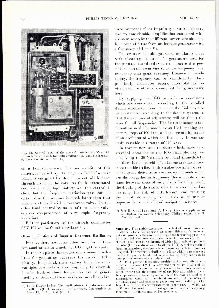
container which is mounted some distance awayfrom the transmitter. Fig. 12 shows this. container.Because of "the low frequency and the small fre-
Fig. 11. Fundamental diagram of the Philips aircraft transmitter SVZ 101. IG = impulsegenerator, Il\-f = impulse mixer, IGO= impulse-governed oscillator, Fl = low-pass filter,l\-f = mixer, ST = driver stage, FD = phase discriminator, va = oscillator with con-tinuously variable frequency, F2 = low-pass filter, FR = frequency control device,ET = output stage, Mod = modulation amplifier.
supplied by M is applied to the phase discriminatorFD, which supplies a control voltage which is fed, viathe filter F2' to the frequency control device FR,which varies the frequency of the driver stage ST.
- The last-mentioned frequency will always adjustitself to a value which is equal to the differencebetween the second harmonic of the IGO and thefrequency of the variable oscillator VOo The last-mentioned is variable between 200 and 300 kc/s, sothat the frequency of the driver stage c,!lnbe varied,by means of VO, over a frequency band of 100 kc/soThe driver stage ST and the IGO may bé adjustedby means of one control knob to the required fre-quency band, and a padding capacitor maintains thefrequency difference between ST and the secondharmonic of the IGO to about 250 kc/so Great accu-racy is not necessary here, for, as has already beenexplained, the frequency of the driver stage isexactly determined by that of the IGO and thevariable oscillator. As the frequency range of the
quency range, the frequency stability of this oscil-lator is very high. In addition, various othermeasures have been taken to increase this stabilityas much as possible. The oscillator valve, for in-stance, has been coupled to the circuit as looselyas possible and special capacitors have been incor-porated to compensate for variations in capacitancesdue to temperature changes. All elements which arepart of the oscillatory circuit, i.e. the coil, thevariable capacitor and the trimmers, are containedin a box made of a material which is a bad heatconductor, so that the temperature of these partswill be substantially the same. Because of theseprecautions, the frequency variation due to a tem-perature èhange of 60 oe was limited to 150 cis.
The frequency control device FR influe~ces thefrequency of the driver stage ST in two ways,namely, both by means of a reactance valve, shuntedacross the oscillator circuit and by a regulatingcoil, also shunted across this circuit, and wound
140 PHILIPS TECHl\'ICAL REVIEW VOL. 14" No. 5
Fig. 12. Control box of the aircraft transmitter SVZ 101.It contains an oscill ator with continuously variable freqnen-cy between 200 and 300 kc/so
on a Ferroxcube core. The permeability of thismaterial is varied by the magnetic field of a yokewhich is energized by direct current which flowsthrough a coil on the yoke. As the last-mentionedcoil has a fairly high inductance, this control isslow, but the frequency variation that can beobtained in this manner is much larger than thatwhich is attained with a reactance valve. On theother hand, control by means of a reactance valveenables compensation of very rapid frequencyvariations.
Further particulars of the aircraft transmitterSVZ 101 will he found elsewhere 13).
Other applications of Impulse Governed Oscillators
Finally, there are some other branches of tele-communications in which an IGO might he useful.
In the first place this system offers many possibi-lities for generating carriers for carrier tele-ph 0n y. In general, these carrier frequencies aremultiples of a certain basic frequency, for example4, kcjs. Each of these frequencies can he gener-ated by an TeO, and these oscillators are all svnchr o-
13) E. H. Hugenhol t z , The application of impulse-governedoscilla tors (IGO) in aircraft transmitters, CommunicationNew, 11, 1~-21, 1950 (No. I).
nized by means of one impulse generator. This maylead to considerable simplification compared witha system whereby the different carriers are obtainedby means of filters from an impulse generator witha frequency of 4 kc/s 14).One or more impulse-governed oscillators may,
with advantage, he used for generators used forfrequency standardization, because it is pos-sible to obtain, from one reference frequency, anyfrequency with great accuracy. Because of decadetuning, the frequency can be read directly, whichpractically eleminatcs errors, interpolations, sooften used in other systems, not being necessaryhere.By applying the IGO principle in receivers
which are constructed according to the so-calleddouble superheterodyne principle, the dial mayalsobe constructed according to the decade system, sothat the accuracy of adjustment will be almost thesame for all frequencies. The first frequency trans-formation might be made by an IGO, making fre-quency steps of 100 kc/s, and the second by meansof an oscillator of which the frequency is continu-ously variable in a range of 100 kc/s.In transmitters and receivers which havc becn
arranged according to the IGO principle, any frc-quency up to 30 Mc/s can he found immediately:i.e. there is no "searching". This ensures faster andmore reliahle traffic. It also makes possible, becauseof the great choice from very many channels whichare close together in frequency (for example a dis-tance between them of only 1 kc/s for telegraphy),the dividing of the traffic over these channels, thuslessening the risk of interference and reducingthe inevitable waiting time. This is of utmostimportance for aircraft and navigation services.
lA) See: D. Goedhart and G. Hepp, Carrier supply in aninstallation for carrier telcphony, Philips tcchn. Rev. 8,137-146, 1946.
Summary. This article describes a method of constructing anoscillator which can operatc at many different frequencics,yet each possesses the same stability as the frequency producedby a crystal oscillator. Only onc crystal is necessary. To dothis, the oscillator is synchronizcd with a harmonic of a periodicimpulse (Impulse-Governed Oscillator, IGO), which is obtainedfrom an impulse generator whose frequency is detennincd bya crystal. The system is similar to a filter which passes a verynarrow frequency band and whose tuning frequency can bechanged by means of a single circuit.
An IGO permits frequency multiplication and division ina ratio of about 1:200. A combination of an IGO and anoscillator with a continuously variable frequency which ismuch lower than the frequency of the IGO and which, there-fore, possesses a high degree of stability, can be used in atransmittcr, which can operate at any required frequency ina certain range and possesses great frequency stability. Otherbranches of the telecommunication technique, in which anIGO can be used to advantage, are: carrier telephony,frequency standards and radio receivers.