Embed Size (px)
Citation preview
Wear 306 (2013) 209–218
Contents lists available at ScienceDirect
Wear
0043-16
http://d
n Corr
fax: þ4
E-m
journal homepage: www.elsevier.com/locate/wear
The influence of start–stop transient velocity on the friction and wearbehaviour of a hyper-eutectic Al–Si automotive alloy
J.C. Walker n, T.J. Kamps, R.J.K. Wood
National Centre for Advanced Tribology at Southampton (nCATS), Highfield Campus, Southampton, SO17 1BJ, UK
a r t i c l e i n f o
Article history:
Received 8 June 2012
Received in revised form
18 October 2012
Accepted 5 November 2012Available online 16 November 2012
Keywords:
FIB–SIMS
Al–Si
Start–stop
Tribo-film
Lubricated sliding
Transient velocity
48/$ - see front matter & 2012 Elsevier B.V. A
x.doi.org/10.1016/j.wear.2012.11.007
esponding author. Tel.: þ44 2380 593761,
4 2380 593016.
ail addresses: [email protected], jcw101@h
a b s t r a c t
As worldwide automotive ownership is set to exceed 2 billion vehicles by 2030 (Dargay et al., 2007 [1]),
environmental and economical pressures on the automotive industry mean there is a trend to reduce
harmful greenhouse gas emissions whilst simultaneously improving fuel economy. The use of electrical
hybrid, start–stop idling and materials light-weighting are some of the technological solutions which can
offer efficiency savings, however their combined use in a tribological context is less well understood.
Interruption of piston sliding as a result of start–stop technology will simultaneously interrupt fluid film
lubrication at the ring/liner interface. This could have implications on the friction and wear behaviour of
Al–Si cylinder blocks, where scuffing can be an issue. In order to determine the effect of a start–stop
velocity cycles on the lubricated friction and wear behaviour of a hyper-eutectic Al–Si liner, an
interrupted reciprocating laboratory tribometer test programme was developed based upon the European
Urban Cycle standard. Refined cast iron piston ring segments were slid at 23 Hz frequency, 4 MPa
nominal contact pressure and 25 mm stroke length against a conformal honed Alusil cylinder liner
segment. Regular velocity interruptions at 60 s intervals did not significantly inhibit the dynamic friction
behaviour between the liner and the cast-iron piston ring segment, indicating that lubricant additive
function was not significantly inhibited. However contact potential and FIB–SIMS depth profiles indicated
that anti-wear tribo-film thickness was reduced as a result of start–stop cycling. Mass loss from the
piston ring was also notably higher as a result of the interruption of elasto-hydrodynamic lubrication
causing boundary conditions at re-start and subsequent 2-body abrasion by harder protruding Si
particles. Specific wear rates for the Al–Si liner as a result of start–stop velocities were surprisingly
lower compared to uninterrupted tests and was believed to be due to faster running-in of the piston ring
surface. These results are discussed in terms of the viability of Al–Si as engine materials running start–
stop technology.
& 2012 Elsevier B.V. All rights reserved.
1. Introduction
For the last decade global automotive manufacturers haveimplemented an array of technological improvements in order toreduce harmful greenhouse gas emissions as well as improve fueleconomy of an ever increasing global automotive market [1]. Thesehave included the introduction of hybrid vehicles that draw powerfrom an internal combustion engine and an electrically chargedsupply, as well as the use of automatic engine controlled start–stoptechnology when vehicles are stationary. Recent reviews havesuggested that implementation of start–stop technology couldadvocate between 3 and 10% efficiency savings per vehicle [2],with the additional possibility of up to 20% saving in CO2
ll rights reserved.
otmail.com (J.C. Walker).
emissions [3]. In addition, the use of light-weighting technologysuch as aluminium or magnesium chassis frames, body panels andengine blocks have also ensured that greenhouse gas emission dueto excess inertial mass is minimised [4]. Such savings and efficiencygains are often measured and bench marked by the use of standardtest cycles such as the European Urban and Extra Urban Cycles [5].
Whilst these technologies are mutually complimentary interms of their environmental benefits, their simultaneous use ina tribological context is less well understood, beyond perhaps anappreciation that start–stop can produces conditions of lubricantstarvation between contacting surfaces and local temperature rise[6,7]. The use of aluminium as a cylinder facing material in theengine block requires that significant amounts of silicon areintroduced into the alloy composition in order to precipitateprimary and secondary Si colonies from a saturated matrix toact as the bearing contact surface against the piston ring pack,thus protecting the softer aluminium from scuffing [8–11]. Whilstthis technology has been fairly well developed for mass produced
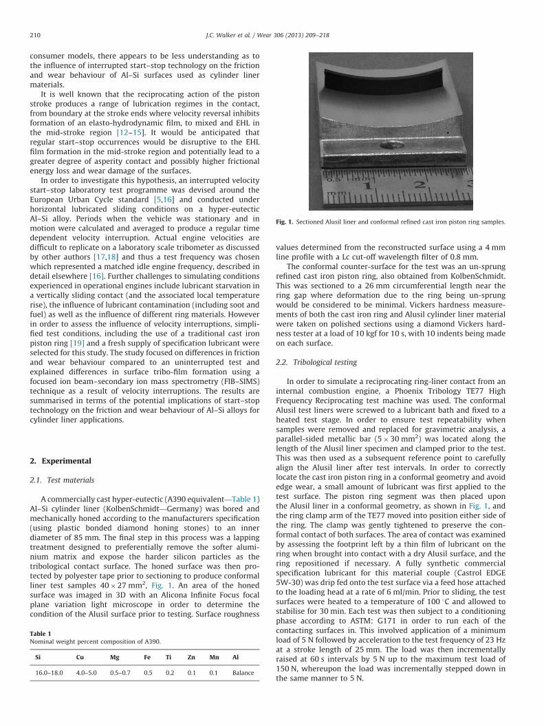
Fig. 1. Sectioned Alusil liner and conformal refined cast iron piston ring samples.
J.C. Walker et al. / Wear 306 (2013) 209–218210
consumer models, there appears to be less understanding as tothe influence of interrupted start–stop technology on the frictionand wear behaviour of Al–Si surfaces used as cylinder linermaterials.
It is well known that the reciprocating action of the pistonstroke produces a range of lubrication regimes in the contact,from boundary at the stroke ends where velocity reversal inhibitsformation of an elasto-hydrodynamic film, to mixed and EHL inthe mid-stroke region [12–15]. It would be anticipated thatregular start–stop occurrences would be disruptive to the EHLfilm formation in the mid-stroke region and potentially lead to agreater degree of asperity contact and possibly higher frictionalenergy loss and wear damage of the surfaces.
In order to investigate this hypothesis, an interrupted velocitystart–stop laboratory test programme was devised around theEuropean Urban Cycle standard [5,16] and conducted underhorizontal lubricated sliding conditions on a hyper-eutecticAl–Si alloy. Periods when the vehicle was stationary and inmotion were calculated and averaged to produce a regular timedependent velocity interruption. Actual engine velocities aredifficult to replicate on a laboratory scale tribometer as discussedby other authors [17,18] and thus a test frequency was chosenwhich represented a matched idle engine frequency, described indetail elsewhere [16]. Further challenges to simulating conditionsexperienced in operational engines include lubricant starvation ina vertically sliding contact (and the associated local temperaturerise), the influence of lubricant contamination (including soot andfuel) as well as the influence of different ring materials. Howeverin order to assess the influence of velocity interruptions, simpli-fied test conditions, including the use of a traditional cast ironpiston ring [19] and a fresh supply of specification lubricant wereselected for this study. The study focused on differences in frictionand wear behaviour compared to an uninterrupted test andexplained differences in surface tribo-film formation using afocused ion beam–secondary ion mass spectrometry (FIB–SIMS)technique as a result of velocity interruptions. The results aresummarised in terms of the potential implications of start–stoptechnology on the friction and wear behaviour of Al–Si alloys forcylinder liner applications.
2. Experimental
2.1. Test materials
A commercially cast hyper-eutectic (A390 equivalent—Table 1)Al–Si cylinder liner (KolbenSchmidt—Germany) was bored andmechanically honed according to the manufacturers specification(using plastic bonded diamond honing stones) to an innerdiameter of 85 mm. The final step in this process was a lappingtreatment designed to preferentially remove the softer alumi-nium matrix and expose the harder silicon particles as thetribological contact surface. The honed surface was then pro-tected by polyester tape prior to sectioning to produce conformalliner test samples 40�27 mm2, Fig. 1. An area of the honedsurface was imaged in 3D with an Alicona Infinite Focus focalplane variation light microscope in order to determine thecondition of the Alusil surface prior to testing. Surface roughness
Table 1Nominal weight percent composition of A390.
Si Cu Mg Fe Ti Zn Mn Al
16.0–18.0 4.0–5.0 0.5–0.7 0.5 0.2 0.1 0.1 Balance
values determined from the reconstructed surface using a 4 mmline profile with a Lc cut-off wavelength filter of 0.8 mm.
The conformal counter-surface for the test was an un-sprungrefined cast iron piston ring, also obtained from KolbenSchmidt.This was sectioned to a 26 mm circumferential length near thering gap where deformation due to the ring being un-sprungwould be considered to be minimal. Vickers hardness measure-ments of both the cast iron ring and Alusil cylinder liner materialwere taken on polished sections using a diamond Vickers hard-ness tester at a load of 10 kgf for 10 s, with 10 indents being madeon each surface.
2.2. Tribological testing
In order to simulate a reciprocating ring-liner contact from aninternal combustion engine, a Phoenix Tribology TE77 HighFrequency Reciprocating test machine was used. The conformalAlusil test liners were screwed to a lubricant bath and fixed to aheated test stage. In order to ensure test repeatability whensamples were removed and replaced for gravimetric analysis, aparallel-sided metallic bar (5�30 mm2) was located along thelength of the Alusil liner specimen and clamped prior to the test.This was then used as a subsequent reference point to carefullyalign the Alusil liner after test intervals. In order to correctlylocate the cast iron piston ring in a conformal geometry and avoidedge wear, a small amount of lubricant was first applied to thetest surface. The piston ring segment was then placed uponthe Alusil liner in a conformal geometry, as shown in Fig. 1, andthe ring clamp arm of the TE77 moved into position either side ofthe ring. The clamp was gently tightened to preserve the con-formal contact of both surfaces. The area of contact was examinedby assessing the footprint left by a thin film of lubricant on thering when brought into contact with a dry Alusil surface, and thering repositioned if necessary. A fully synthetic commercialspecification lubricant for this material couple (Castrol EDGE5W-30) was drip fed onto the test surface via a feed hose attachedto the loading head at a rate of 6 ml/min. Prior to sliding, the testsurfaces were heated to a temperature of 100 1C and allowed tostabilise for 30 min. Each test was then subject to a conditioningphase according to ASTM: G171 in order to run each of thecontacting surfaces in. This involved application of a minimumload of 5 N followed by acceleration to the test frequency of 23 Hzat a stroke length of 25 mm. The load was then incrementallyraised at 60 s intervals by 5 N up to the maximum test load of150 N, whereupon the load was incrementally stepped down inthe same manner to 5 N.
J.C. Walker et al. / Wear 306 (2013) 209–218 211
2.3. Start–stop velocity testing
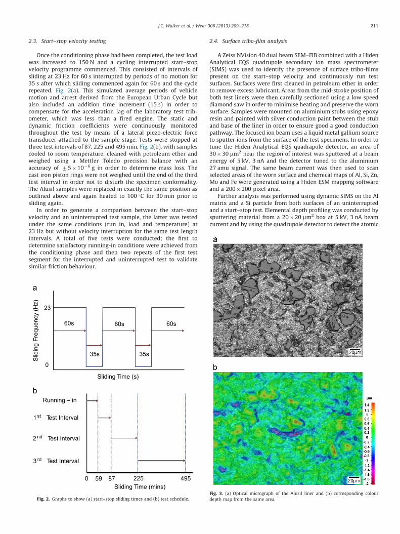
Once the conditioning phase had been completed, the test loadwas increased to 150 N and a cycling interrupted start–stopvelocity programme commenced. This consisted of intervals ofsliding at 23 Hz for 60 s interrupted by periods of no motion for35 s after which sliding commenced again for 60 s and the cyclerepeated, Fig. 2(a). This simulated average periods of vehiclemotion and arrest derived from the European Urban Cycle butalso included an addition time increment (15 s) in order tocompensate for the acceleration lag of the laboratory test trib-ometer, which was less than a fired engine. The static anddynamic friction coefficients were continuously monitoredthroughout the test by means of a lateral piezo-electric forcetransducer attached to the sample stage. Tests were stopped atthree test intervals of 87, 225 and 495 min, Fig. 2(b), with samplescooled to room temperature, cleaned with petroleum ether andweighed using a Mettler Toledo precision balance with anaccuracy of 75�10�6 g in order to determine mass loss. Thecast iron piston rings were not weighed until the end of the thirdtest interval in order not to disturb the specimen conformality.The Alusil samples were replaced in exactly the same position asoutlined above and again heated to 100 1C for 30 min prior tosliding again.
In order to generate a comparison between the start–stopvelocity and an uninterrupted test sample, the latter was testedunder the same conditions (run in, load and temperature) at23 Hz but without velocity interruption for the same test lengthintervals. A total of five tests were conducted; the first todetermine satisfactory running-in conditions were achieved fromthe conditioning phase and then two repeats of the first testsegment for the interrupted and uninterrupted test to validatesimilar friction behaviour.
Sliding Time (mins)87 495225
1 st Test Interval
2 nd Test Interval
3 rd Test Interval
0 59
Slid
ing
Freq
uenc
y (H
z)
0
23
Sliding Time (s)
60s 60s 60s
35s 35s
Fig. 2. Graphs to show (a) start–stop sliding times and (b) test schedule.
2.4. Surface tribo-film analysis
A Zeiss NVision 40 dual beam SEM–FIB combined with a HidenAnalytical EQS quadrupole secondary ion mass spectrometer(SIMS) was used to identify the presence of surface tribo-filmspresent on the start–stop velocity and continuously run testsurfaces. Surfaces were first cleaned in petroleum ether in orderto remove excess lubricant. Areas from the mid-stroke position ofboth test liners were then carefully sectioned using a low-speeddiamond saw in order to minimise heating and preserve the wornsurface. Samples were mounted on aluminium stubs using epoxyresin and painted with silver conduction paint between the stuband base of the liner in order to ensure good a good conductionpathway. The focused ion beam uses a liquid metal gallium sourceto sputter ions from the surface of the test specimens. In order totune the Hiden Analytical EQS quadrapole detector, an area of30�30 mm2 near the region of interest was sputtered at a beamenergy of 5 kV, 3 nA and the detector tuned to the aluminium27 amu signal. The same beam current was then used to scanselected areas of the worn surface and chemical maps of Al, Si, Zn,Mo and Fe were generated using a Hiden ESM mapping softwareand a 200�200 pixel area.
Further analysis was performed using dynamic SIMS on the Almatrix and a Si particle from both surfaces of an uninterruptedand a start–stop test. Elemental depth profiling was conducted bysputtering material from a 20�20 mm2 box at 5 kV, 3 nA beamcurrent and by using the quadrupole detector to detect the atomic
Fig. 3. (a) Optical micrograph of the Alusil liner and (b) corresponding colour
depth map from the same area.
J.C. Walker et al. / Wear 306 (2013) 209–218212
mass units signal from the same elements as above, as a functionof time. In order to accurately convert sputter time to depth, SEMstereo-microscopy was performed on each FIB sputtered crater.Three eucentric tilted secondary electron images were taken ofeach crater at 51, 01 and �51 stage tilt angles. The images werereconstructed in 3D using Mex software (Alicona, Austria) and alinear cross section profile used to measure the depth of the FIBsputtered crater compared to nearby un-sputtered material.Assuming a linear sputter rate for all species, the time dependentdynamic SIMS profiles could be converted to accurate depthprofiles and tribo-film thicknesses subsequently calculated andcompared between samples. Error bounds were calculated basedon the surface roughness of the un-sputtered and sputtered cratersurface.
3. Results
3.1. Surface properties
Optical microscopy of the honed surface, Fig. 3(a) showed howthe surfaces of equiaxed primary silicon phases were exposedwithin the aluminium matrix. The honing lay direction wasclearly visible from both the optical image and the surface depthmap, Fig. 3(b) which also indicated that the larger primary siliconparticles were raised above the aluminium matrix to a maximumheight of round 1.5 mm. The surface roughness (Ra) from this areaof the sample was measured to be 0.2970.02 mm, which wasmarginally above engine bore surface finish specification forAlusil (0.21 mm Ra). The relative Vickers hardness (HV) of theAlusil liner and refined cast iron piston ring were 13873 and296714 respectively, although for the Alusil liner the hardness
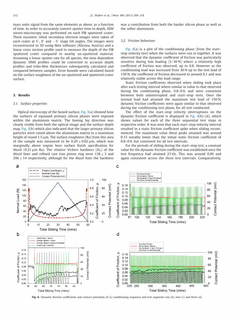
Fig. 4. Dynamic friction coefficients and contact potentials of (a) condi
was a contribution from both the harder silicon phase as well asthe softer aluminium.
3.2. Friction behaviour
Fig. 4(a) is a plot of the conditioning phase (from the start–stop velocity test) when the surfaces were run in together. It wasobserved that the dynamic coefficient of friction was particularlysensitive during low loading (5–30 N) where a relatively highcoefficient of friction was observed, up to 0.8. However as theconditioning load was increased from 30 N up to the test load of150 N, the coefficient of friction decreased to around 0.1 and wasrelatively stable across this load range.
Static friction coefficients observed when sliding took placeafter each testing interval where similar in value to that observedduring the conditioning phase, 0.8–0.9, and were consistentbetween both uninterrupted and start–stop tests. Once thenormal load had attained the maximum test load of 150 N,dynamic friction coefficients were again similar to that observedduring the conditioning test phase, for all test conducted.
The effect of the start–stop velocity interruptions on thedynamic friction coefficient is displayed in Fig. 4(b)–(d), whichshows values for each of the three sequential test steps inrespective order. It was seen that each start–stop velocity intervalresulted in a static friction coefficient spike when sliding recom-menced. The maximum value these peaks attained was around0.15 notably lower than the initial static friction coefficient of0.8–0.9, but consistent for all test intervals.
For the periods of sliding during the start–stop test, a constantvalue for the dynamic friction coefficient was established once thetest frequency had attained 23 Hz. This was around 0.09 andagain consistent across the three test intervals. Comparatively,
tioning sequence and test segments one (b), two (c) and three (d).
J.C. Walker et al. / Wear 306 (2013) 209–218 213
the dynamic friction coefficient of the uninterrupted run test wasvery similar at 0.1, slightly above the start–stop test until thethird test segment, when values were identical at 0.09.
3.3. Surface Contact Potential
Fig. 4(b)–(d) gives an indication of the measured electricalcontact potential between the cast iron ring and Alusil liner.During the conditioning run in phase, it was observed thatformation of an insulating tribo-layer occurred relatively quickly,Fig. 4(a), which was sensitive to changes in the test load. This wasnoted in Fig. 4(b) immediately after the conditioning phase, whenthe increase of the test load to 150 N resulted in the contactpotential being significantly reduced from 47 to 7 mV or 1 mV forthe uninterrupted and interrupted start–stop tests respectively,after about 59 min. For the second and third test segments,Fig. 4(c) and (d), this initial drop was observed to be notably less(second segment—48 mV to 26 and 20 mV; third segment—48 mV to 34 and 22 mV, respectively). For the uninterrupted testit was observed that as the test progressed, the contact potentialsteadily increased, plateauing after approximately 75 min. Thestart–stop test also exhibited a steady increase in electricalcontact resistance when sliding, similarly plateauing afterapproximately 75 min, however there were some notable differ-ences. The most obvious was that when the test velocity wasinterrupted, the contact potential fell to zero. The second obser-vation was that when sliding recommenced, the contact potentialincreased again, usually to a higher level than that observed justprior to the velocity interruption. This was followed by a steadydecrease in the value until the next velocity transient caused thevalue to drop to zero again. This effect was consistent across alltests. At longer sliding times, a small increase in the maximumcontact potential compared to values attained after 75 min wasnoted, however of more significance was the fact that the contact
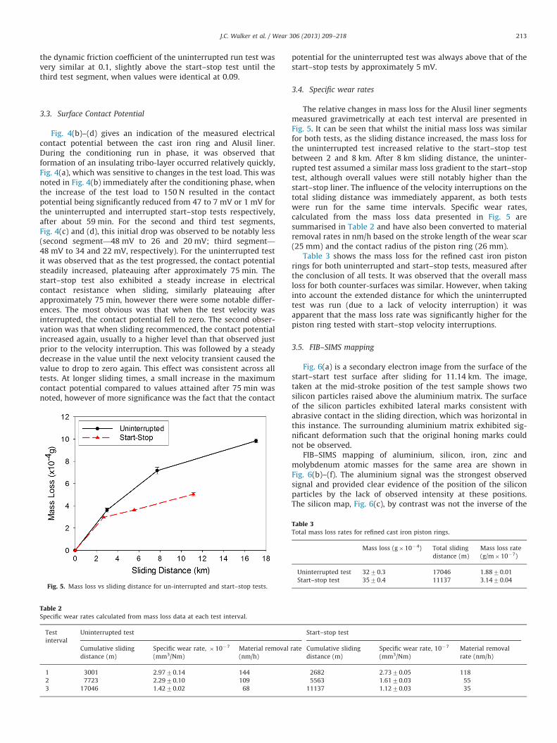
Fig. 5. Mass loss vs sliding distance for un-interrupted and start–stop tests.
Table 2Specific wear rates calculated from mass loss data at each test interval.
Test
interval
Uninterrupted test
Cumulative sliding
distance (m)
Specific wear rate, �10�7
(mm3/Nm)
Material removal
(nm/h)
1 3001 2.9770.14 144
2 7723 2.2970.10 109
3 17046 1.4270.02 68
potential for the uninterrupted test was always above that of thestart–stop tests by approximately 5 mV.
3.4. Specific wear rates
The relative changes in mass loss for the Alusil liner segmentsmeasured gravimetrically at each test interval are presented inFig. 5. It can be seen that whilst the initial mass loss was similarfor both tests, as the sliding distance increased, the mass loss forthe uninterrupted test increased relative to the start–stop testbetween 2 and 8 km. After 8 km sliding distance, the uninter-rupted test assumed a similar mass loss gradient to the start–stoptest, although overall values were still notably higher than thestart–stop liner. The influence of the velocity interruptions on thetotal sliding distance was immediately apparent, as both testswere run for the same time intervals. Specific wear rates,calculated from the mass loss data presented in Fig. 5 aresummarised in Table 2 and have also been converted to materialremoval rates in nm/h based on the stroke length of the wear scar(25 mm) and the contact radius of the piston ring (26 mm).
Table 3 shows the mass loss for the refined cast iron pistonrings for both uninterrupted and start–stop tests, measured afterthe conclusion of all tests. It was observed that the overall massloss for both counter-surfaces was similar. However, when takinginto account the extended distance for which the uninterruptedtest was run (due to a lack of velocity interruption) it wasapparent that the mass loss rate was significantly higher for thepiston ring tested with start–stop velocity interruptions.
3.5. FIB–SIMS mapping
Fig. 6(a) is a secondary electron image from the surface of thestart–start test surface after sliding for 11.14 km. The image,taken at the mid-stroke position of the test sample shows twosilicon particles raised above the aluminium matrix. The surfaceof the silicon particles exhibited lateral marks consistent withabrasive contact in the sliding direction, which was horizontal inthis instance. The surrounding aluminium matrix exhibited sig-nificant deformation such that the original honing marks couldnot be observed.
FIB–SIMS mapping of aluminium, silicon, iron, zinc andmolybdenum atomic masses for the same area are shown inFig. 6(b)–(f). The aluminium signal was the strongest observedsignal and provided clear evidence of the position of the siliconparticles by the lack of observed intensity at these positions.The silicon map, Fig. 6(c), by contrast was not the inverse of the
Start–stop test
rate Cumulative sliding
distance (m)
Specific wear rate, 10�7
(mm3/Nm)
Material removal
rate (nm/h)
2682 2.7370.05 118
5563 1.6170.03 55
11137 1.1270.03 35
Table 3Total mass loss rates for refined cast iron piston rings.
Mass loss (g�10�4) Total sliding
distance (m)
Mass loss rate
(g/m�10�7)
Uninterrupted test 3270.3 17046 1.8870.01
Start–stop test 3570.4 11137 3.1470.04
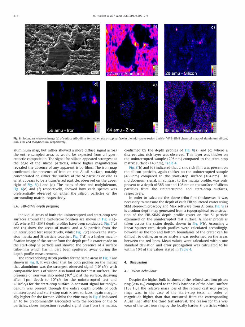
Fig. 6. Secondary electron image (a) of surface tribo-films formed on start–stop surface in the mid-stroke region and (b–f) FIB–SIMS chemical maps of aluminium, silicon,
iron, zinc and molybdenum, respectively.
J.C. Walker et al. / Wear 306 (2013) 209–218214
aluminium map, but rather showed a more diffuse signal acrossthe entire sampled area, as would be expected from a hyper-eutectic composition. The signal for silicon appeared strongest atthe edge of the silicon particles, where higher magnificationrevealed the absence of any apparent tribo-films. The iron mapconfirmed the presence of iron on the Alusil surface, notablyconcentrated on either the surface of the Si particles or else aswhat appears to be a transferred particle, observed on the upperright of Fig. 6(a) and (d). The maps of zinc and molybdenum,Fig. 6(e) and (f) respectively, showed how each species waspreferentially observed on either the silicon particles or thesurrounding matrix, respectively.
3.6. FIB–SIMS depth profiling
Individual areas of both the uninterrupted and start–stop testsurfaces around the mid-stroke position are shown in Fig. 7(a)–(d), where FIB–SIMS depth profiles have been conducted. Fig. 7(a)and (b) show the areas of matrix and a Si particle from theuninterrupted test respectively, whilst Fig. 7(c) shows the start–stop matrix and Si particle together. Fig. 7(d) is a higher magni-fication image of the corner from the depth profile crater made onthe start–stop Si particle and showed the presence of a surfacetribo-film which has in part been sputtered away during thedepth profile measurement.
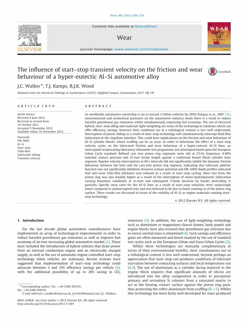
The corresponding depth profiles for the same areas in Fig. 7 areshown in Fig. 8. It was clear that for both profiles on the matrixthat aluminium was the strongest observed signal (105 c/s), withcomparable levels of silicon also found on both test surfaces. Thepresence of iron was also noted (104 c/s) at the surface, decayingafter 1 mm depth to 103 c/s for the uninterrupted test andE102 c/s for the start–stop surface. A constant signal for molyb-denum was present through the entire depth profile of bothuninterrupted and start–stop matrix test surfaces, again margin-ally higher for the former. Whilst the zinc map in Fig. 6 indicatedZn to be predominantly associated with the location of the Siparticles, closer inspection revealed signal also from the matrix,
confirmed by the depth profiles of Fig. 8(a) and (c) where adiscreet zinc rich layer was observed. This layer was thicker onthe uninterrupted sample (295 nm) compared to the start–stopmatrix surface (143 nm), Table 4.
Fig. 8(b) and (d) indicated that a zinc rich film was present onthe silicon particles, again thicker on the uninterrupted sample(436 nm) compared to the start–stop surface (184 nm). Themolybdenum signal, in contrast to the matrix profile, was onlypresent to a depth of 385 nm and 108 nm on the surface of siliconparticles from the uninterrupted and start–stop surfaces,respectively.
In order to calculate the above tribo-film thicknesses it wasnecessary to measure the depth of each FIB sputtered crater usingSEM stereo-microscopy and Mex software from Alicona. Fig. 9(a)is a colour depth map generated from a topographical reconstruc-tion of the FIB–SIMS depth profile crater on the Si particleexamined on the uninterrupted test surface. A linear profile istaken across the crater depth, shown in Fig. 9(b). Assuming alinear sputter rate, depth profiles were calculated accordingly,however as the top and bottom boundaries of the crater can bedifficult to define, an error analysis was performed on the areasbetween the red lines. Mean values were calculated within onestandard deviation and error propagation was calculated to bewithin 10% of the values stated in Table 4.
4. Discussion
4.1. Wear behaviour
Despite the higher bulk hardness of the refined cast iron pistonring (296 HV) compared to the bulk hardness of the Alusil surface(138 HV), the relative mass loss of the refined cast iron pistonrings was, in the case of the start–stop tests, an order ofmagnitude higher than that measured from the correspondingAlusil liner after the third test interval. The reason for this waswear of the cast iron ring by the locally harder Si particles which
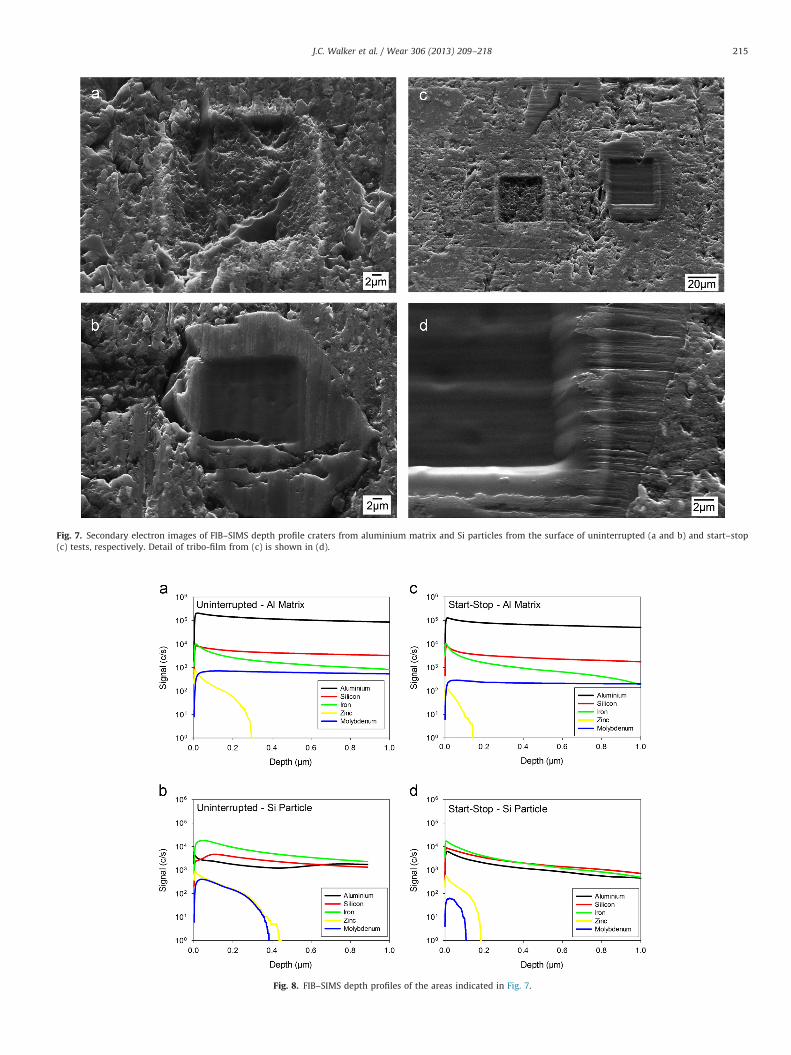
Fig. 7. Secondary electron images of FIB–SIMS depth profile craters from aluminium matrix and Si particles from the surface of uninterrupted (a and b) and start–stop
(c) tests, respectively. Detail of tribo-film from (c) is shown in (d).
Fig. 8. FIB–SIMS depth profiles of the areas indicated in Fig. 7.
J.C. Walker et al. / Wear 306 (2013) 209–218 215
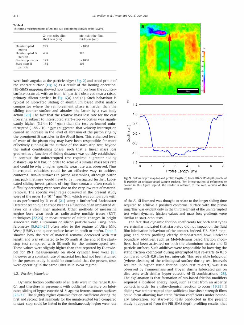
Table 4Thickness measurements of Zn and Mo containing surface tribo-layers.
Zn-rich tribo-film
thickness (nm)
Mo-rich tribo-film
thickness (nm)
Uninterrupted
matrix
295 41000
Uninterrupted Si
particle
436 385
Start–stop matrix 143 41000
Start–stop Si
particle
184 108
Fig. 9. Colour depth map (a) and profile length (b) from FIB–SIMS depth profile of
Si particle on uninterrupted sample surface. (For interpretation of references to
colour in this figure legend, the reader is referred to the web version of this
article.)
J.C. Walker et al. / Wear 306 (2013) 209–218216
were both angular at the particle edges (Fig. 2) and stood proud ofthe contact surface (Fig. 6) as a result of the honing operation.FIB–SIMS mapping showed how transfer of iron from the counter-surface occurred, with an iron rich particle observed near a raisedprimary silicon particle in Fig. 6(a) and (d). Such behaviour istypical of lubricated sliding of aluminium based metal matrixcomposites where the reinforcement phase is harder than thesliding counter-surface and abrades the latter by a two-bodyaction [20]. The fact that the relative mass loss rate for the castiron ring subject to interrupted start–stop velocities was signifi-cantly higher (3.14�10�7 g/m) than the test performed unin-terrupted (1.88�10�7 g/m) suggested that velocity interruptioncaused an increase in the level of abrasion of the piston ring bythe prominent Si particles in the Alusil liner. This enhanced levelof wear of the piston ring may have been responsible for moreeffectively running-in the surface of the start–stop test, beyondthe initial conditioning phase, such that a linear mass lossgradient as a function of sliding distance was quickly established.In contrast the uninterrupted test required a greater slidingdistance (up to 8 km) in order to achieve a similar mass loss rateand could be why a higher specific wear rate was observed. Thusinterrupted velocities could be an effective way to achieveconformal run-in surfaces in piston assemblies, although pistonring pack lifetimes would have to be investigated further. Lubri-cated sliding investigations of ring–liner contacts often result indifficulty detecting wear rates due to the very low rate of materialremoval. The specific wear rates observed in the present studywere of the order 1�10�7 mm3/Nm, which was comparable withtests performed by Li et al [21] using a Rutherford BackscatterDetector technique to trace wear as a function of an implanted Aulayer on a steel liner material. Other methods of measuringengine bore wear such as radio-active nuclide tracer (RNT)techniques [22,23] or measurement of subtle changes in heightassociated with aluminium or silicon particle wear using inter-ferometry [8,9,24–27] often refer to the regime of Ultra MildWear (UMW) and quote surface losses in nm/h or nm/m. Table 2showed how the rate of material removal decreased with testlength and was estimated to be 35 nm/h at the end of the start–stop test compared with 68 nm/h for the uninterrupted test.These values were slightly higher than that reported by Dienwie-bel for RNT measurements on Al–Si cylinder bore wear [8],however as a constant rate of material loss had not been attainedin the present study, it could be concluded that the present testswere operating in the same Ultra Mild Wear regime.
4.2. Friction behaviour
Dynamic friction coefficients of all tests were in the range 0.08–0.1 and therefore in agreement with published literature on lubri-cated sliding of hyper-eutectic Al–Si against ferrous counter-surfaces[28–31]. The slightly higher dynamic friction coefficient during thefirst and second test segments for the uninterrupted test, comparedto start–stop, could be linked to the simultaneously higher wear rate
of the Al–Si liner and was thought to relate to the longer sliding timerequired to achieve a polished conformal surface with the pistonring. This was evident only in the third segment of the uninterruptedtest when dynamic friction values and mass loss gradients weresimilar to start–stop tests.
The fact that dynamic friction coefficients for both test typeswere similar indicated that start–stop did not impact on the fluidfilm lubrication behaviour of the contact. Indeed, FIB–SIMS map-ping and depth profiling clearly demonstrated how lubricantboundary additives, such as Molybdenum based friction modi-fiers, had been activated on both the aluminium matrix and Siparticle surfaces. Such additives were responsible for lowering thestatic friction coefficient during interrupted test re-starts to 0.15compared to 0.8–0.9 after test intervals. This reversible behaviour(where cleaning of the tribological surface during test intervalsresulted in higher static friction upon test re-start) was alsoobserved by Timmermans and Froyen during lubricated pin ondisc tests with similar hyper-eutectic Al–Si combinations [28].The explanation is that formation of Mo-based friction modifiersrequired a localised energy input, such as that from an asperitycontact, in order for a tribo-chemical reaction to occur [19,32]. Ifsliding was uninterrupted then sufficient low shear strength filmscould form allowing low static friction coefficients under bound-ary lubrication. For start–stop tests conducted in the presentstudy, it appeared from the FIB-SIMS depth profiling results, that
J.C. Walker et al. / Wear 306 (2013) 209–218 217
there was little change in Mo-based low friction tribo-filmthickness on the aluminium matrix (Fig. 8) compared to theuninterrupted tests. The presence of Mo was also observed on theload bearing Si particles and whilst the thickness of this layer wasnotably less for the start–stop tests, it appeared that even thepresence of a very think Mo layer could provide similar dynamicfriction coefficients compared to the uninterrupted test.
4.3. Surface tribo-layer
On-line contact potential measurements measured duringtesting contributed further information about formation of sur-face tribo-films. It was clear from Fig. 4(a) that load influenced theformation of surface insulating tribo-layers as contact potentialsdropped with an increase in conditioning and test load. When thetest load was reduced the surface tribo-film re-formed, increasingthe contact potential between the surfaces and illustrating thesensitivity of surface tribo-film formation to contact conditions.
The contact potential was also sensitive to start–stop velocityinterruptions. It was interesting that during all velocity interrup-tions the contact potential fell to zero, indicating metallic contactbetween the piston ring and Alusil liner. This was furtherevidence of boundary additive function reducing the static re-start friction coefficient to 0.15. When re-starting, contact poten-tial readings exhibited a peak associated with the static frictionpeak, again confirming tribo-chemical reaction associated withfrictional energy input from local flash temperatures and alsoconsistent with other studies on anti-wear pad formation[19,31,33,34].
It was clear when comparing contact potential between thestart–stop and uninterrupted tests that values were higher for thelatter indicating a thicker tribo-film, which was consistent withZn-based anti-wear pad thickness measured by FIB–SIMS. Overthe total test length, contact potential values steadily increasedwith test time, again consistent with the theory that anti-wearfilm formation and growth required sliding to occur [29,33–36].
Depth profiling showed that whilst lubricant additive functionwas not inhibited for start–stop tests, anti-wear pad formation onsilicon and aluminium contact surfaces was not as effectivecompared to uninterrupted tests. This was a direct result of themetallic contact resulting from the velocity interruption and thesubsequent re-starting of sliding. The FIB–SIMS mapping clearlyshowed regions of preferential Zn and Mo rich layers dissociatedon silicon and matrix respectively, although as shown from thedepth profiles in Fig. 8 this was not exclusively the case, withsmall amounts of Mo on Si and Zn in the matrix. This was broadlyconsistent with work by Nicholls et al. [34,36,37] who used anumber of X-Ray techniques (XANES, X-PEEM) to determine themechanism of preferential long chain poly-phosphate anti-wearpad formation from ZDDP additives at contacting Si interfaces.The presence of iron was also noted on the contact surface of theSi particles, Fig. 5(d), and would be consistent with the theorythat a ferrous oxide surface is necessary to allow desorption of Znbased additives prior to formation of a glassy phosphate anti-wear pad [19,31,34,36,38]. The presence of Al also on the surfaceof the Si particles, Fig. 8(b) suggested that the anti-wear padformation on Si particles resulted from the wear, transfer andmixing of debris caused during the initial running-in period ofsliding, which would be in agreement with more recent theoriesof how Al–Si surfaces evolve as a result of lubricated slidingwear [8]. This would also explain the presence of a small amountof Mo present on the Si particle surface, although it was clearfrom the FIB–SIMS mapping that the majority of the Mo signalwas found in the Al matrix. Similar studies on hyper-eutecticAl–Si alloys using Mo-based additives [31,36] have found MoS2
formation to be independent of substrate composition and thus
the present work suggests that the difference in Mo signalobserved between matrix and Si particles is more influenced bysliding contact then chemical desorption. Si particles are consid-ered the load bearing element of the liner surface, but thepresence of even 100 nm of Mo-based friction modifier,Fig. 8(d), was sufficient to reduce the static friction coefficientduring the start–stop cycles, Fig. 4.
Placing the current work in a wider context, it was clear thatwhilst friction behaviour was not significantly inhibited, start–stop interrupted velocities had a detrimental effect on the thick-ness of anti-wear film formation on Al–Si cylinder liner materials.This could have lifecycle implications for wear when using thesematerials in hybrid or start–stop engine applications. The fre-quency of test interruptions may play a factor in the timerequired for an effective tribo-film to be generated, competingwith tribo-film removal as a result of velocity interruption and isclearly an area that warrants further investigation.
5. Conclusions
Summarising the main findings of this work we can concludethe following:
�
A preliminary start–stop test programme for hyper-eutecticAl–Si alloys developed based around the European Urban Cycleto simulate lubricated sliding of the piston ring/cylinder linerinterface using a laboratory based tribometer. � It was shown that start–stop sliding against a hyper-eutecticAl–Si cylinder liner caused more wear to the cast iron pistonring compared to an uninterrupted test.
� Quicker running in of the cast iron piston ring as a result ofstart–stop sliding reduced wear rates of the Al–Si surface ascontact loads were more evenly distributed.
� Start–stop sliding did not significantly affect dynamic frictioncoefficients or friction modifier activation.
� Transfer of ferrous material from the counter-surface wasassociated with concurrent formation of Zn-based anti-wearpads on protruding Si particles, consistent with other reportsin the literature.
� Contact potential and FIB–SIMS depth profiling indicated anincrease in boundary lubrication contact at the mid-strokeregion of the Al–Si cylinder surface resulting in a decrease inZn-based anti-wear pad thickness.
� These findings may have implications for the use of hyper-eutectic Al–Si cylinder liner in start–stop engine cycles,although further work is required to establish the long termeffects over vehicle lifetimes.
Acknowledgements
The authors would like to acknowledge access to the South-ampton Nanofabrication Centre (SNC) for use of the Zeiss NVision40 dual beam FIB–SEM.
References
[1] J. Dargay, D. Gately, M. Sommer, Vehicle ownership and income growth,Worldwide: 1960–2030, Energy Journal 28 (2007) 143.
[2] J. King, The King Review of Low-Carbon Cars: the Potential for CO2 Reduction,HM Stationery Office, 2007.
[3] N. Fonseca, J. Casanova, M. Valdes, Influence of the stop/start system on CO2
emissions of a diesel vehicle in urban traffic, Transportation Research Part D:Transport and Environment 16 (2011) 194–200.
[4] IAI, Improving Sustainability in the Transport Sector Through Weight Reduc-tion and the Application of Aluminium-Model, 2008.
J.C. Walker et al. / Wear 306 (2013) 209–218218
[5] Member Council Directive, 70/220/EEC, With Revisions to 2007, EuropeanUnion, 1970.
[6] G. Ryk, Y. Kligerman, I. Etsion, Experimental investigation of laser surfacetexturing for reciprocating automotive components, Tribology Transactions45 (2002) 444–449.
[7] Y. Kagohara, S. Takayanagi, S. Haneda, M. Fujita, Y. Iwai, Tribological propertyof plain bearing with low frictional layer, Tribology International 42 (2009)1800–1806.
[8] M. Dienwiebel, K. Pohlmann, M. Scherge, Origins of the wear resistance ofAlSi cylinder bore surfaces studies by surface analytical tools, TribologyInternational 40 (2007) 1597–1602.
[9] B. Slattery, T. Perry, A. Edrisy, Microstructural evolution of a eutectic Al–Siengine subjected to severe running conditions, Materials Science and Engi-neering: A 512 (2009) 76–81.
[10] F. Davis, T. Eyre, The effect of silicon content and morphology on the wear ofaluminium–silicon alloys under dry and lubricated sliding conditions, Tribol-ogy International 27 (1994) 171–181.
[11] E. Kohler, J. Niehues, Aluminum-matrix composite materials in combustionengines, in: K.U. Kainer (Ed.), Metal Matrix Composites, Wiley-VCH,Weinheim, 2006, pp. 95–109.
[12] R. Taylor, Transient effects in engines operating at steady speeds and loads,Tribology and Interface Engineering Series 43 (2003) 123–131.
[13] B.J. Hamrock, S.R. Schmid, B.O. Jacobson, Fundamentals of Fluid FilmLubrication, CRC press, New York, 2004.
[14] D. Dowson, G.R. Higginson, Elasto-hydrodynamic Lubrication, PergamonPress, Oxford, 1977.
[15] C.F. Taylor, The Internal-combustion Engine in Theory and Practice: Thermo-dynamics, Fluid Flow, Performance, M.I.T. Press, Cambridge, 1985.
[16] J.C. Walker, T.J. Kamps, R.J.K. Wood, Assessment of 3D surface textureevolution of a hypereutectic Al–Si liner subject to transient velocities, in:W.J. Bartz (Ed.) Proceedings of the 18th International Colloguium onTribology, TAE Esslingen, 2012.
[17] P.M. Lee, R.J. Chittenden, Consideration of test parameters in reciprocatingtribometers used to replicate ring-on-liner contact, Tribology Letters 39(2010) 81–89.
[18] S.E. Hartfield-Wunsch, S.C. Tung, C.J. Rivard, Development of a Bench WearTest for the Evaluation of Engine Cyliner Components and the Correlationwith Engine Test Results, Society of Automotive Engineers, 1993.
[19] A. Neville, A. Morina, T. Haque, M. Voong, Compatibility between tribologicalsurfaces and lubricant additives—How friction and wear reduction can becontrolled by surface/lube synergies, Tribology International 40 (2007)1680–1695.
[20] J.C. Walker, W.M. Rainforth, H. Jones, Lubricated sliding wear of behaviour ofalumninium alloy composites, Wear 259 (2005) 577–589.
[21] Y.R. Li, D. Shakhvorostov, G. Pereira, A. Lachenwitzer, W. Lennard, P. Norton,A. Novel, Method for quantitative determination of ultra-low wear rates ofmaterials, part I: on steels, Tribology Letters 33 (2009) 143–152.
[22] M. Scherge, K. Pohlmann, A. Gerve, Wear measurement using radionuclide-technique (RNT), Wear 254 (2003) 801–817.
[23] E.W. Schneider, D.H. Blossfeld, Radiotracer method for measuring real-timepiston-ring and cylinder-bore wear in spark-ignition engines, Nuclear Instru-ments and Methods in Physics Research Section A: Accelerators, Spectro-meters, Detectors and Associated Equipment 505 (2003) 559–563.
[24] M. Chen, A. Alpas, Ultra-mild wear of a hypereutectic Al–18.5 wt% Si alloy,Wear 265 (2008) 186–195.
[25] M. Chen, T. Perry, A. Alpas, Ultra-mild wear in eutectic Al–Si alloys, Wear 263(2007) 552–561.
[26] B. Slattery, A. Edrisy, T. Perry, Investigation of wear induced surface andsubsurface deformation in a linerless Al–Si engine, Wear 269 (2010)298–309.
[27] S. Dey, T. Perry, A. Alpas, Micromechanisms of low load wear in an Al–18.5%Si alloy, Wear 267 (2009) 515–524.
[28] G. Timmermans, L. Froyen, Tribological performance of hypereutectic P/MAl–Si during sliding in oil, Wear 231 (1999) 77–88.
[29] A.N.K. Jadoon, R.A. Mufti, Tribological behaviour of alternate hypereutecticAl–Si alloys with different antiwear additives, Tribology—Materials Surfacesand Interfaces 4 (2010) 61–73.
[30] S. Das, S.K. Biswas, Boundary lubricated tribology of an aluminium–siliconalloy sliding against steel, Tribology Letters 17 (2004) 623–628.
[31] X. Xia, A. Morina, A. Neville, M. Priest, R. Roshan, C.P. Warrens, M.J. Payne,Tribological performance of an Al–Si alloy lubricated in the boundary regimewith zinc dialkyldithiophosphate and molybdenum dithiocarbamate addi-tives, Proceedings of the Institution of Mechanical Engineers Part J: Journal ofEngineering Tribology 222 (2008) 305–314.
[32] R.F. Haycock, A.J. Caines, J.E. Hillier, Automotive Lubricants Reference Book,John Wiley & Sons Inc., New York, 2005.
[33] A.M. Barnes, K.D. Bartle, V.R.A. Thibon, A review of zinc dialkyldithiopho-sphates (ZDDPS): characterisation and role in the lubricating oil, TribologyInternational 34 (2001) 389–395.
[34] M.A. Nicholls, T. Do, P.R. Norton, M. Kasrai, G.M. Bancroft, Review of thelubrication of metallic surfaces by zinc dialkyl–dithiophosphates, TribologyInternational 38 (2005) 15–39.
[35] A. Morina, A. Neville, M. Priest, J. Green, ZDDP and MoDTC interactions andtheir effect on tribological performance—tribofilm characteristics and itsevolution, Tribology Letters 24 (2006) 243–256.
[36] A. Jimenez, A. Morina, A. Neville, M. Bermudez, Surface interactions andtribochemistry in boundary lubrication of hypereutectic aluminium–siliconalloys, Proceedings of the Institution of Mechanical Engineers Part J: Journalof Engineering Tribology 223 (2009) 593–601.
[37] M.A. Nicholls, P.R. Norton, G.M. Bancroft, M. Kasrai, G.D. Stasio, L.M. Wiese,Spatially resolved nanoscale chemical and mechanical characterization ofZDDP antiwear films on aluminum–silicon alloys under cylinder/bore wearconditions, Tribology Letters 18 (2005) 261–278.
[38] G. Pereira, A. Lachenwitzer, M. Nicholls, M. Kasrai, P. Norton, G. Stasio,Chemical characterization and nanomechanical properties of antiwear filmsfabricated from ZDDP on a near hypereutectic Al–Si alloy, Tribology Letters18 (2005) 411–427.