Embed Size (px)
Citation preview
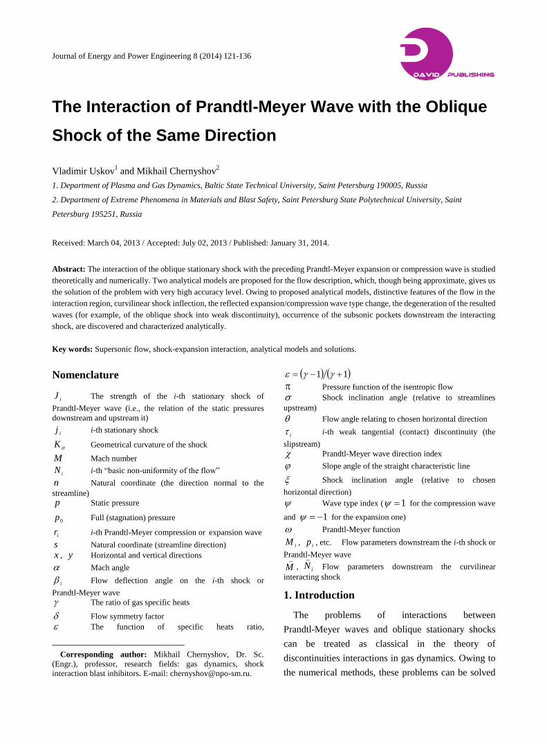
Journal of Energy and Power Engineering 8 (2014) 121-136
The Interaction of Prandtl-Meyer Wave with the Oblique
Shock of the Same Direction
Vladimir Uskov1 and Mikhail Chernyshov
2
1. Department of Plasma and Gas Dynamics, Baltic State Technical University, Saint Petersburg 190005, Russia
2. Department of Extreme Phenomena in Materials and Blast Safety, Saint Petersburg State Polytechnical University, Saint
Petersburg 195251, Russia
Received: March 04, 2013 / Accepted: July 02, 2013 / Published: January 31, 2014.
Abstract: The interaction of the oblique stationary shock with the preceding Prandtl-Meyer expansion or compression wave is studied
theoretically and numerically. Two analytical models are proposed for the flow description, which, though being approximate, gives us
the solution of the problem with very high accuracy level. Owing to proposed analytical models, distinctive features of the flow in the
interaction region, curvilinear shock inflection, the reflected expansion/compression wave type change, the degeneration of the resulted
waves (for example, of the oblique shock into weak discontinuity), occurrence of the subsonic pockets downstream the interacting
shock, are discovered and characterized analytically.
Key words: Supersonic flow, shock-expansion interaction, analytical models and solutions.
Nomenclature
iJ The strength of the i-th stationary shock of
Prandtl-Meyer wave (i.e., the relation of the static pressures
downstream and upstream it)
ij i-th stationary shock
K Geometrical curvature of the shock
M Mach number
iN i-th “basic non-uniformity of the flow”
n Natural coordinate (the direction normal to the
streamline)
p Static pressure
0p Full (stagnation) pressure
ir i-th Prandtl-Meyer compression or expansion wave
s Natural coordinate (streamline direction)
x , y Horizontal and vertical directions
Mach angle
i Flow deflection angle on the i-th shock or
Prandtl-Meyer wave
The ratio of gas specific heats
Flow symmetry factor
The function of specific heats ratio,
Corresponding author: Mikhail Chernyshov, Dr. Sc.
(Engr.), professor, research fields: gas dynamics, shock
interaction blast inhibitors. E-mail: [email protected].
11
Pressure function of the isentropic flow
Shock inclination angle (relative to streamlines
upstream)
Flow angle relating to chosen horizontal direction
i i-th weak tangential (contact) discontinuity (the
slipstream)
Prandtl-Meyer wave direction index
Slope angle of the straight characteristic line
Shock inclination angle (relative to chosen
horizontal direction)
Wave type index ( 1 for the compression wave
and 1 for the expansion one)
Prandtl-Meyer function
iM , ip , etc. Flow parameters downstream the i-th shock or
Prandtl-Meyer wave
M
, iN
Flow parameters downstream the curvilinear
interacting shock
1. Introduction
The problems of interactions between
Prandtl-Meyer waves and oblique stationary shocks
can be treated as classical in the theory of
discontinuities interactions in gas dynamics. Owing to
the numerical methods, these problems can be solved
D DAVID PUBLISHING
The Interaction of Prandtl-Meyer Wave with the Oblique Shock of the Same Direction
122
in each separate case. But, in spite of the long history of studies [1], full theoretical analysis of the solution has not been executed yet. A lack of exact analytical relations as well as the complexity of the flow (the interaction is not localized at a single point and even in any finite region) is the main obstacles in the way of theoretical study.
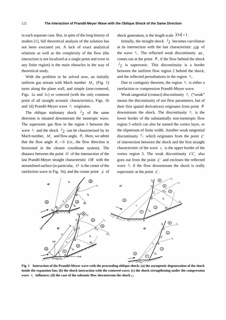
With the problem to be solved now, an initially uniform gas stream with Mach number 0M (Fig. 1) turns along the plane wall, and simple (non-centered, Figs. 1a and 1c) or centered (with the only common point of all straight acoustic characteristics, Figs. 1b and 1d) Prandtl-Meyer wave 1r originates.
The oblique stationary shock 2j of the same direction is situated downstream the isentropic wave. The supersonic gas flow in the region 1 between the wave 1r and the shock 2j can be characterized by its Mach number, 1M and flow angle, 1θ . Here, we admit that the flow angle 01 =θ (i.e., the flow direction is horizontal in the chosen coordinate system). The distance between the point O of the intersection of the last Prandtl-Meyer straight characteristic OB with the streamlined surface (in particular, O is the center of the rarefaction wave in Fig. 1b), and the corner point A of
shock generation, is the length scale 1=OA . Initially, the straight shock 2j becomes curvilinear
at its intersection with the last characteristic OB of the wave 1r . The reflected weak discontinuity 1BB comes out at the point B , if the flow behind the shock
2j is supersonic. This discontinuity is a border between the uniform flow region 2 behind the shock, and the reflected perturbations in the region 3r .
Due to contiguity theorem, the region 3r is either a rarefaction or compression Prandtl-Meyer wave.
Weak tangential (contact) discontinuity 1τ (“weak” means the discontinuity of not flow parameters, but of their first spatial derivatives) originates from point B downstream the shock. The discontinuity 1τ is the lower border of the substantially non-isentropic flow region 5 which can also be named the vortex layer, or the slipstream of finite width. Another weak tangential discontinuity 2τ which originates from the point C of intersection between the shock and the first straight characteristic of the wave 1r is the upper border of the vortex region 5. The weak discontinuity 1CC also goes out from the point C and encloses the reflected wave 3r if the flow downstream the shock is really supersonic at the point C .
Fig. 1 Interaction of the Prandtl-Meyer wave with the proceeding oblique shock: (a) the asymptotic degeneration of the shock inside the expansion fan; (b) the shock interaction with the centered wave; (c) the shock strengthening under the compression wave 1r influence; (d) the case of the subsonic flow downstream the shock j2.

The Interaction of Prandtl-Meyer Wave with the Oblique Shock of the Same Direction
123
If the Prandtl-Meyer expansion wave is too strong, then the curvilinear shock degenerates into one more weak discontinuity inside the expansion fan (Fig. 1a). The discontinuity 2τ does not exist there, and non-interacted part 4r of the wave 1r serves instead of the shock 4j which comes through the expansion fan otherwise.
The oblique shock 4j (Figs. 1b-1d) or the expansion wave 4r (Fig. 1a) of the same direction as the wave 1r and the shock 2j (direction index 1=χ ) as well as the reflected isentropic wave 3r of the opposite direction ( 1−=χ ) result due to the interaction considered. If the flow downstream the shock is subsonic, then the Prandtl-Meyer wave 3r does not exist, and the results of interaction sufficiently depend upon the perturbation induced downstream. We do not consider the latter type of interaction, except of several complementary remarks.
We should emphasize that the wave 3r is also partly a result of the refraction of the perturbations reflected from the shock in the region 2BCC on the vortex flow layer. At this refraction, the perturbations reflected from the non-isentropic layer 5 are generated in their turn. These reflected perturbations distribute along the characteristics of the first family, overtake the shock situated upstream them, influence its features and shape, and make it curvilinear even after point C. That is why the shock 4j can not be formally called straight, and the flow behind it (in the region 4) is not exactly uniform and isentropic.
The main goals of the present study are to define and analyze the shape and the other features of the interacting shock, to find out the type of the resulted perturbations and their transition criteria, as well as some special features of the considered interaction, and the influence of the ratio of gas specific heats on the problem solution.
2. Materials and Methods
2.1 Non-uniformities of the Two-Dimensional Gas Flow
To characterize not only flow parameters, but also
their spatial derivatives at the non-uniform stream of a perfect inviscid gas, we introduce so-called in Ref. [2] “basic non-uniformities” given from two-dimensional flow equations in natural coordinates:
0sin142
2
=+∂∂
+− θθ
γN
nMM ,
npNM ∂∂−= ln22γ ,
00 =∂∂ sp .
Here, spN ∂∂= ln1 expresses the flow non-isobaricity, sN ∂∂= θ2 is the geometric curvature of streamlines, the quantity npN ∂∂= 03 ln characterizes the flow vorticity (i.e., its non-isentropic features), and yN δ=4 expresses the type of flow symmetry ( 04 ≡N for the plane flow considered here). Also, here s and n are natural coordinates counted along and normally the sreamlines, correspondingly; M is the local Mach number; p is the static pressure;
0p is the full (stagnation) pressure of the flow; y is the distance to the axis of symmetry in axis-symmetric flow; 0=δ and 1=δ for the plane flow and for the axis-symmetric one, correspondingly; γ is the ratio of specific heats ( 4.1=γ everywhere if not specifically mentioned otherwise).
The geometrical curvature σK of the shock conventionally remarked here as the additional non-uniformity ( σKN ≡5 ). We admit that the curvature 0>σK for the shocks convex downwards (for instance, the shocks BE in Fig. 1b, and BC in Fig. 1c), and 0>σK for shocks convex upwards (e.g., the shock EC in Fig. 1b, and the shock after the point E in Fig. 1a).
2.2 Prandtl-Meyer Flow Non-uniformities and the Envelope Line of Its Straight Characteristics
The variation of gas stream parameters at Prandtl-Meyer wave can be described by using the isentropic flow functions. So the wave intensity, i.e., the relation 1J of the static pressures behind the wave and after this one:
( ) ( )011 MMJ ππ= (1)
The Interaction of Prandtl-Meyer Wave with the Oblique Shock of the Same Direction
124
where, ( ) ( )( ) ( )1215.01 −−−+=
γγγπ MM is the
isentropic pressure function. The Prandtl-Meyer wave deflection angle is:
( ) ( )( )MM ωωχβ −= 01 (2)
Here, 1=χ is the wave direction index, and: ( ) ( ) 1arctan1arctan1 22 −−−= MMM εεω (3)
is the Prandtl-Meyer function, such as:
( ) ( )( )( )11
112
2
−+−−
=MMM
dMMd
εεω (4)
( ) ( )11 +−= γγε Analogously, the strength of the reflected wave 3r
and flow deflection angle are: ( ) ( )23233 MMppJ ππ== (5)
( ) ( )( )233 MM ωωχβ −= (6)
where, 1−=χ ; 2p , 2M , 3p and 3M are pressures and Mach numbers of the flow in regions 2 and 3 (Fig. 1b), consequently.
Later we have to deal with not only the whole waves
1r and 3r but with their parts the shock wave has just interacted. Such is the sector of the wave 1r bounded by the characteristics OB and EE1 in Fig. 1b. The flow deflection angle ( )ϕβ1 and the strength ( )ϕ
1J of this part of the wave are expressed by the formulas:
( ) ( ) ( )( )11 MM ωωχβ ϕ −= (7) ( ) ( ) ( )01 MMJ ππϕ = (8)
Here, ( )ϕMM ≡ is the Mach number at the characteristic EE1 determined by the angle ϕ of its inclination:
( ) ( ) ( )[ ]MMM αωωχθϕ +−+= 00 (9)
where, ( ) ( )MM 1arcsin=α is the Mach angle. In a similar manner, the strength of the corresponding sector of the reflected wave 3r after the interaction between the shock and the above-mentioned sector of the wave 1r is determined as:
( ) ( )( ) ( )233 MMJ ππ ϕϕ = (10)
The flow deflection angle is ( ) ( )( ) ( )( )233 MM ωωχβ ϕϕ −= (11)
where, 1−=χ , and ( )ϕ3M is Mach number at the last
characteristic of the corresponding reflected wave sector. We also designate Mach number of the flow just after the voluntary point of the interacting shock as
( )ϕMM)) ˆ≡ , the flow deflection angle at the interaction
shock as β , and the shock strength (relation of static pressures downstream the shock and upstream it) as J .
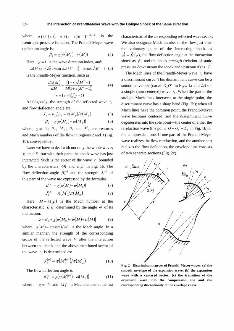
The Mach lines of the Prandtl-Meyer wave 1r have a discriminant curve. This discriminant curve can be a smooth envelope (curve OO ′0 in Figs. 1a and 2a) for a simple (non-centered) wave 1r . When the part of the straight Mach lines intersects at the single point, the discriminant curve has a sharp bend (Fig. 2b); when all Mach lines have the common point, the Prandtl-Meyer wave becomes centered, and the discriminant curve degenerates into the sole point—the center of either the rarefaction wave (the point 10 EOO ≡≡ in Fig. 1b) or the compression one. If one part of the Prandtl-Meyer wave realizes the flow rarefaction, and the another part realizes the flow deflection, the envelope line consists of two separate sections (Fig. 2c).
Fig. 2 Discriminant curves of Prandtl-Meyer waves: (a) the smooth envelope of the expansion wave; (b) the expansion wave with a centered sector; (c) the transition of the expansion wave into the compression one and the corresponding discontinuity of the envelope curve.
(a) (b)
(c)

The Interaction of Prandtl-Meyer Wave with the Oblique Shock of the Same Direction
125
The shape of the envelope of the straight Mach lines family is defined by any given streamline of this wave unambiguously. Let the only streamline equation
( )00 xy (for example, the section AB of the impermeable surface in Fig. 2a) to be given, as well as the initial Mach number 0M and flow angle 0θ . An equation of one-parameter family of the straight characteristics looks like:
( ) ( ) ( )0000 tan xxxxyy −⋅+= ϕ (12)
where, 0x is the parameter. The inclination angle ϕ of any straight Mach line
and Mach number M on this one are defined by ( )00 xy ′ through Eq. (9) and the following:
( ) ( )( )[ ]MMy ωωχθ −+=′000 tan (13)
The equation ( )ΓΓ xy for the envelope of the straight family of Mach lines is derived from Eqs. (3), (4), (9), (12) and (13) at the condition 00 =∂∂ xy [3]:
( )( ) ϕεχ cos11
23
2
NMMxx −−
=−Γ
( )( ) ϕεχ sin11
23
2
NMMyy −−
=−Γ
( )( )3
2
2 11MN
Mr −−=
ε
Here, 10CCr = is the distance from the voluntary point 1C at a straight characteristic to the corresponding point 0C at the envelope line. In particular, at 0xx ≡ , 0yy ≡ , 2N is the curvature of the given streamline, and the envelope ( )ΓΓ xy can be easily built.
The two first basic non-uniformities of the Prandtl-Meyer flow are inversely proportional to the distance r to the envelope along the characteristic line:
( )rM
MN 11 2
1−+
=εψ (14)
( )( )3
2
211
rMMN −−
=εχψ (15)
(here 1=ψ for the compression wave, and 1−=ψ for the expansion one).
The spatial derivative of any variable flow parameter
f given in the voluntary direction qρ inside Prandtl-Meyer wave depends on the angle between qρ and gradient vector grad f which is normal to the straight characteristics:
fqqf grad⋅=∂∂ρ
(16)
The Eqs. (9), (13) and (16), and the well-known functions of the isentropic flow allow us to calculate all flow parameters derivatives along the direction of the oblique shock coming through Prandtl-Meyer fan of characteristics situated upstream.
2.3 Dynamic Compatibility Conditions at Stationary Shocks
Among the numerous variables for shock description, we choose the shock strength J (i.e., the relation of the static pressures downstream and upstream the shock) as the main parameter. We denote below that J is the strength of the shock inside the Prandtl-Meyer fan, 122 ppJ = is the strength of the shock 2j , and
4J is the strength of the resulting shock 4j . Here, 1p is the pressure in zone 1, and 2p is the pressure in zone 2 of the flow (Fig. 1).
The shock strength here is the main quantity binding flow parameters before and behind the shock. For example, Mach numbers 2M (downstream the shock
2j ) and 1M (upstream the shock) relate between themselves as it follows:
( ) ( )( )( )22
22
212
2 111
JJJMJ
Mε
εε+
−−−+= (17)
The flow deflection angle 2β also depends upon the shock strength:
( ) ( )( )( ) ( )( )⎥
⎥⎦
⎤
⎢⎢⎣
⎡
−−−+−−
+−
=11
11arctan21
2
2
212 JMJ
JJ
JMJ
m
m
εεε
εβ (18)
Here, ( ) ( ) εε −+= 21 MMJ m is the strength of the normal shock in the flow with Mach number M . The relations analogous to Eqs. (17) and (18) are correct for the shock 4j :
( ) ( )( )( )44
24
204
4 111
JJJMJ
Mε
εε+
−−−+= (19)
The Interaction of Prandtl-Meyer Wave with the Oblique Shock of the Same Direction
126
( )( )( )( )⎥
⎥⎦
⎤
⎢⎢⎣
⎡
−−−+−−
+−
=11
11arctan40
4
4
404 JJ
JJ
JJ
m
m
εεε
εβ (20)
(here, ( )00 MJJ mm ≡ ) and also for any point at the interacting part BC of the shock considered:
( ) ( )( )( )JJ
JMJMε
εε+
−−−+=
111 22)
(21)
( ) ( )( )( ) ( )( )⎥
⎥⎦
⎤
⎢⎢⎣
⎡
−−−+−−
+−
=111
11arctan 2 JMJ
JJMJm
εεε
εβ (22)
The angle σ of shock inclination relative to the flow velocity vector upstream the given point is also bound with shock strength ( J ) and local Mach number upstream ( M ):
( ) εσε −+= 22 sin1 MJ (23)
In the coordinate system admitted here, Eq. (23) determines the dependence of shock slope angle ξ (Fig. 1) on the shock strength:
( )ϕβσξ 1+= (24)
that is an equivalent to the quantity ( )σσ xy ′ where ( )σσ xy is the shock shape looked for.
Except of ( )MJ m , we must emphasize here the following special shock strengths: the strength of the shock declining the flow to a maximum angle possible at a given Mach number:
( ) ( )( ) 21212
22
2 2222
+−++⎟⎟⎠
⎞⎜⎜⎝
⎛ −+
−= MMMMJl ε
and the strength of the shock reducing the flow velocity downstream it to the critical speed:
( ) ( ) 112
12
1 2222
* +−+⎟⎟⎠
⎞⎜⎜⎝
⎛ −+
−= MMMMJ ε
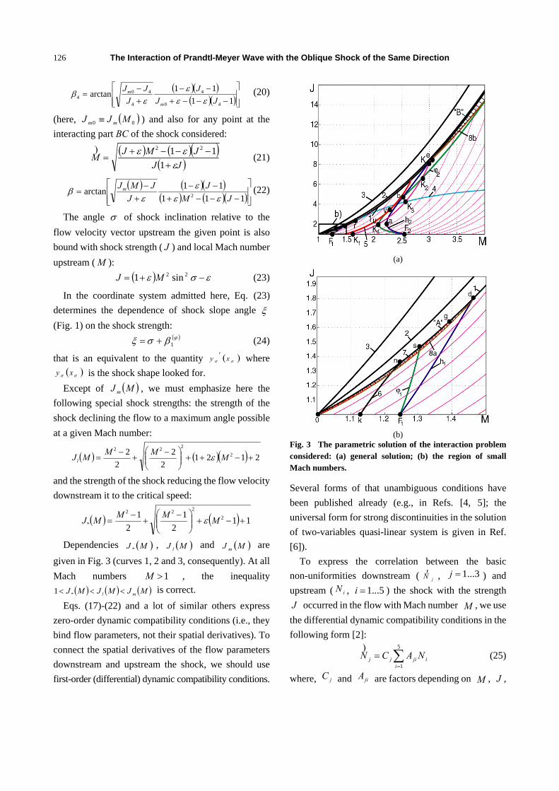
Dependencies ( )MJ * , ( )MJ l and ( )MJ m are given in Fig. 3 (curves 1, 2 and 3, consequently). At all Mach numbers 1>M , the inequality
( ) ( ) ( )MJMJMJ ml <<< *1 is correct. Eqs. (17)-(22) and a lot of similar others express
zero-order dynamic compatibility conditions (i.e., they bind flow parameters, not their spatial derivatives). To connect the spatial derivatives of the flow parameters downstream and upstream the shock, we should use first-order (differential) dynamic compatibility conditions.
(a)
(b)
Fig. 3 The parametric solution of the interaction problem considered: (a) general solution; (b) the region of small Mach numbers.
Several forms of that unambiguous conditions have been published already (e.g., in Refs. [4, 5]; the universal form for strong discontinuities in the solution of two-variables quasi-linear system is given in Ref. [6]).
To express the correlation between the basic non-uniformities downstream ( jN
) , 3...1=j ) and upstream ( iN , 5...1=i ) the shock with the strength J occurred in the flow with Mach number M , we use the differential dynamic compatibility conditions in the following form [2]:
∑=
=5
1iijijj NACN
) (25)
where, jC and jiA are factors depending on M , J ,

The Interaction of Prandtl-Meyer Wave with the Oblique Shock of the Same Direction
127
shock direction χ ( 1=χ everywhere at the present study), and the flow angle θ (only at axis-symmetric flow). The factors we are interested in look as:
( )( )11 −= JbC γ ,
( ) ( )( )11 32 −−= JbJС ε ,
( )( ) ( )[ ]pmpmp
m
cJJbJJaJJA +−−−
++
−= 2311
1εε
γ,
( ) ( )[ ]θθθ εεε
χ cJbJasA +++++
−= 212 1
,
( )( )ωωωεχ cJbJaA −−−−= 215 1 ,
( )[ ]γχ2
2121 1 fcJf
JsA m −+= ,
( ) ⎥⎦
⎤⎢⎣
⎡−+
−+
−= 2122 1fJJf
JJcA m
m
εε
,
( ) ( )( ) ( )( )[ ]{ }11211225
−+−++−++⋅⋅=
JJJJJJmJaA
m εεε
where: ( )( )[ ] 21ε+−= JJJa m ,
( )22 1 Jab ε++= ,
( ) ( )[ ] 21εε ++= mJJc ,
( ) ( )[ ] 21ε+−= mm JJJs ,
( )( )εε −−−= 431 mp Ja ,
( ) ( ) ( )222 36431223 εεεεε −+−+−−−= mmp JJb ,
( )( )( )εε ++−= mmmp JJJc 11 ,
( ) ( )[ ]εεε +−+−=Θ 141 mJa ,
( ) ( )( ) ( )( )2123112 εεεε −−+−+=Θ mJb ,
( ) ( )( )εεε +−+=Θ mJc 11 2 ,
ε+= 3wa ,
ε323 −−= mw Jb ,
( ) 141 ++= mw Jc ε ;
( ) ( ) ( )( )JJJmJmJf m −++++= 21 12 εεμ ,
( )( ) ( )( )( )JJJJJmf mm −−−++−= 22 112 εεεγ ,
( ) ( ) ( )[ ]JJbJm εεε ++−+= 111 ,
( ) ( )( )[ ] 111 −+++−= εεεμ mm JJ .
To define the flow non-uniformities downstream
the shock, as seen from Eq. (25), it is enough to know the geometrical curvature of the shock ( σKN ≡5 ).
2.4 Interaction of the Oblique Shock with Preceding Overtaking Weak Discontinuities
The last ( OB ) and the first ( CO0 , Figs. 1b-1d) straight characteristics of the wave 1r are the weak discontinuities, i.e., the discontinuities of the basic non-uniformities 1N and 2N . Since these non-uniformities are equal to zero in zone 0 and correspond to Eqs. (14) and (15) inside Prandtl-Mayer wave, we can determine the discontinuities [ ]1N and [ ]2N at the characteristic line CO0 :
[ ] ( )rM
MN 11 2
1−+
=εψ (26)
[ ] ( )( )3
2
211
rMMN −−
=εψ (27)
On the contrary, the flow is non-uniform (also corresponds to Eqs. (14) and (15)) before the Mach line OB and uniform behind it. So the discontinuities of the basic non-uniformities at the last characteristic of the Prandtl-Meyer wave are:
[ ] ( )rM
MN 11 2
1−+
−=εψ (28)
[ ] ( )( )3
2
211
rMMN −−
−=εψ (29)
The distance r for centered or non-centered wave, as it was shown in Subsection 2.2, can be easily determined owing to the given equation of the streamlined surface.
It is worthy of notice from Eqs. (26)-(29) that the relation:
[ ] ( )[ ] 021 =Γ− NMN χ expresses the dynamical conditions of compatibility at weak discontinuities of gas flow parameters (here
( ) 122 −=Γ MMM γ ; 1=χ for wave 1r with the straight characteristics of the first family).
The problem of the interaction of the stationary shock with the preceding overtaking weak discontinuity has the following solution [2] in variables accepted here:

The Interaction of Prandtl-Meyer Wave with the Oblique Shock of the Same Direction
128
[ ][ ]
( ) ( )252151
2221212111
2 ACACAACAAC
NK
Γ++ΓΓ++Γ
= ))
σ (30)
Here, ( )MΓ≡Γ , ( )M))
Γ≡Γ , M is the Mach number upstream the point of the intersection, and M
) is the Mach number behind the shock at this point (for example, 1MM = and 2MM =
) at point B ).
Eqs. (27), (29) and (30) allow us not only to define the discontinuities of shock curvature at points B and C , but also to determine the shock curvature just after the point B quite exactly ( [ ]σσ KK = , Eq. (29)). Declaring that the curvature of the shock
4j is equal to zero right after the point C , we can determine the shock curvature of the interacting shock BC just before this point ( [ ]σσ KK −= , Eq. (27)). But, as it was shown in Section 1, this assumption is not absolutely exact and needs some proof for its introduction.
2.5 Problem Solution Based on the Assumption of Zero Curvature of the Resulting Shock
The calculations carried out by the second-order method of characteristics at utmost asymptotic refining of the numerical grid have shown that the shock 4j is of an extremely small curvature (in particular, at point C ). For example, in case of the interaction with the centered expansion fan, its curvature is equal to
6102 −⋅ at 5.11 =M , 8.01 =J and 4.12 =J ; to 5103 −⋅ at 31 =M , 4.01 =J and 42 =J ; to 6104 −⋅
at 51 =M , 3.01 =J and 102 =J . The intersection with the weak discontinuity CO0 diminishes the shock geometric curvature approximately by 1,200 times in the first case, by 800 times in the second case, and by 4,500 times in the third one. So we can conclude that the curvature of the shock 4j is very small compared with the curvature of the interacting shock BC and can be accepted to be equal to zero. Then the curvature of the shock BC at point С can be easily determined from Eqs. (27) and (30): [ ]σσ KK −= .
Let us now consider the shock which has interacted not with the whole expansion fan, but with its part bounded by the straight characteristics OB and EE1 (Figs. 1a and 1b). The following interaction of this
shock with the remaining part of the wave does not change the shock section EC . So the assumption of zero shock curvature at the point of its exit out of the Prandtl-Meyer fan is equivalent to the possibility of using the relation analogous to Eq. (30) at all inner points of the interacting shock:
( ) ( )2
252151
2221212111 NACAC
AACAACK ⋅
Γ++ΓΓ++Γ
= ))
σ (31)
Considering Eqs. (15), (21) and (31), we conclude that the dimensionless curvature of the interacting shock depends only on wave type 1±=ψ , the shock strength J and the local Mach number M upstream:
( ) ( )
( )( ) .11 3
2
252151
2221212111
MM
ACACAACAACrK
−−×
×Γ+
+ΓΓ++Γ⋅=
ε
ψσ ))
Since ( )( ) 232''' 1 σσσ yyK += , where, ( )σσ xy is the shape of the shock, Eq. (31) allows us to determine the shape of the shock in the interaction region. Eqs. (17)-(23) binding shock shape and strength and Eqs. (2)-(4), (9) and (12)-(16) which allow us to calculate flow parameters derivatives at all points and in all directions inside the Prandtl-Meyer fan lead to the following equations complementary to Eq. (31):
( ) MfJdMdJ 32 ε+= , (32)
( )( )
( )42
2
3 11111 f
JJMJ
MMf m ⋅
+−
⋅−+
−−+=
εεε ,
( ) ( )( ) ( )252151
22212121114 sin
1ACACMAACAAC
fΓ+⋅−+ΓΓ++Γ
−= ))
ασ,
where, to exclude trigonometric expressions,
( ) ( )( ) ( )ε
εασ
+
−−−+=−
11
sin2
2
MJMJMJ m
(the intermediate calculations are contained in Ref. [7]).
Taking into account that the derivative dMdJ does not depend on upstream flow non-uniformities, we must conclude that Eq. (32) is most convenient to solve the problem. Neither initial data ( 1M , 2J , etc.) nor local non-uniformities, but only local Mach number M and shock strength J participate in this

The Interaction of Prandtl-Meyer Wave with the Oblique Shock of the Same Direction
129
equation. The integral curves of Eq. (32) are shown in Figs. 3a and 3b as slim lines. The shock strength decrease under the influence of the rarefaction wave corresponds to the motion downward these curves; the increase of the strength J at the interaction with the compression wave corresponds to the motion upward. Mach number at sonic line 1 ( ( )MJJ *= there) or on abscissa axis ( 1=J ; that corresponds to the shock degeneration) can be considered as the only parameter.
In fact, the assumption of zero curvature of the resulted shock implied the neglect to the influence of the perturbations refracted at the entropy layer on the shock parameters. These assumptions concerning the moving shock waves in non-steady flow underlie Chester, Chisnell and Whitham’s approximate analytical methods [8]. Analogous assumptions concerning shocks in steady flow were introduced in Ref. [9] and other studies.
2.6 The Solution Based on the Static Pressure Equality and Collinearity of Flow Directions Downstream the Resulting Waves
The straightness of the shock 4J in Fig. 1 is possible only at the absence of the perturbations which overtakes the shock from behind. The equality of static pressures and the collinearity of the streams on both sides of vortex layer 5 is a necessary (not sufficient, though) condition for it. These conditions can be formulated as the system binding wave strengths iJ and deflection angles iβ ( 4...1=i ):
4321 JJJJ = (33) ( ) ( ) ( )
( )404
323212101
,,,,
JMJMJMJM
ββββ
==++
(34)
Shock strengths 2J and 4J , corresponding deflection angles, and Mach numbers are tied together with Eqs. (17)-(20), and the same flow variables upstream and downstream Prandtl-Meyer waves are bound with Eqs. (1), (2), (5) and (6).
Using Eq. (33) in logarithmic form ( ii Jln=Λ ), it is not difficult to solve the system Eqs. (33) and (34) owing to the well-known technique of shock and
expansion-compression polars. Like Eq. (30) in the previous model, Eqs. (33) and
(34) can be generalized for the inner points of the interacting curvilinear shock:
( ) ( ) JJJJ =ϕϕ321 (35)
( ) ( ) ( )( ) ( )( ) ( )( ) ( )( )JMJM
JMJM,,
,,
323
21211
ϕββ
βϕβϕϕ
ϕϕ
=+
++ (36)
Here, ( )ϕM is Mach number at a straight characteristic coming into the given point of the shock;
( ) ( ) ( )( )ϕππϕ MMJ 11 = is the strength of the Prandtl-Meyer wave part which have just interacted with the shock; ( ) ( )( ) ( )233 MMJ ππ ϕϕ = is the strength of the corresponding part of the reflected wave 3r ;
( )ϕ3M is the Mach number at the last characteristic of
this reflected part; ( )ϕβ 1 and ( )ϕβ 3
are the flow deflection angles at the named parts of the waves 1r and 3r . Shock strengths 2J and J , corresponding deflection angles, and the Mach numbers are tied here by Eqs. (17), (18), (21) and (22). Corresponding flow parameters at Prandtl-Meyer wave sectors are bound by Eqs. (7), (8), (10) and (11).
The system Eqs. (35) and (36) determines the local shock strength J and deflection angle β in any inner point of the interacting shock.
Differentiating Eqs. (35) and (36), we can get the expressions analogous to Eq. (31) for the shock curvature, and the expressions analogous to Eq. (32) for the shock strength variation. But, unlike in Eqs. (31) and (32), the initial parameters ( 1M and 2J ) are present in these expressions which become rather more complicated [7]. So the solutions of Eqs. (33) and (34) do not compose the one-parameter family of curves at the ( )JM , -plane. The system Eqs. (33) and (34) is definitely not an integral of Eq. (32).
Conditions Eqs. (33) and (34) were, in fact, introduced in Ref. [10] to solve the problem of the interaction between the shock and Prandtl-Meyer wave of opposite direction [11]. Eqs. (33)-(36) are formally analogous to the compatibility conditions in the case of two overtaking shocks intersections. But Eqs. (33) and
The Interaction of Prandtl-Meyer Wave with the Oblique Shock of the Same Direction
130
(34) give us, as a rule, only an approximate solution of the problem because we neglect the influence of refracted perturbations on flow downstream the shock
4j and the wave 3r .
3. Results and Discussion
3.1 The Accuracy of the Methods Proposed
The results achieved due to the “differential” model Eqs. (31) and (32) and the “integral” one Eqs. (35) and (36) demonstrate a very high accuracy.
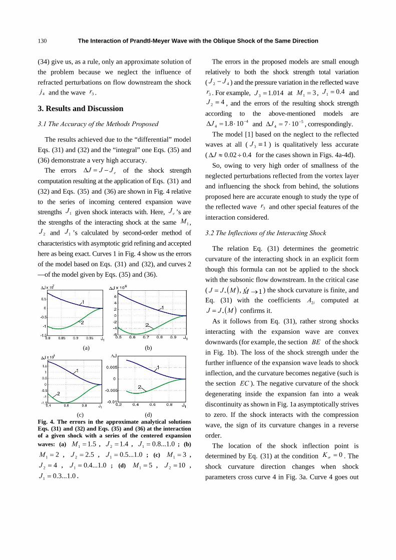
The errors eJJJ −=Δ of the shock strength computation resulting at the application of Eqs. (31) and (32) and Eqs. (35) and (36) are shown in Fig. 4 relative to the series of incoming centered expansion wave strengths 1J given shock interacts with. Here, eJ ’s are the strengths of the interacting shock at the same 1M ,
2J and 1J ’s calculated by second-order method of characteristics with asymptotic grid refining and accepted here as being exact. Curves 1 in Fig. 4 show us the errors of the model based on Eqs. (31) and (32), and curves 2 —of the model given by Eqs. (35) and (36).
(a) (b)
(c) (d)
Fig. 4. The errors in the approximate analytical solutions Eqs. (31) and (32) and Eqs. (35) and (36) at the interaction of a given shock with a series of the centered expansion waves: (a) 5.11 =M , 4.12 =J , 0.1...8.01 =J ; (b)
21 =M , 5.22 =J , 0.1...5.01 =J ; (c) 31 =M ,
42 =J , 0.1...4.01 =J ; (d) 51 =M , 102 =J ,
0.1...3.01 =J .
The errors in the proposed models are small enough relatively to both the shock strength total variation ( 42 JJ − ) and the pressure variation in the reflected wave
3r . For example, 014.13 =J at 31 =M , 4.01 =J and 42 =J , and the errors of the resulting shock strength
according to the above-mentioned models are 4
4 108.1 −⋅=ΔJ and 54 107 −⋅=ΔJ , correspondingly.
The model [1] based on the neglect to the reflected waves at all ( 13 ≡J ) is qualitatively less accurate ( 4.002.0 ÷≈ΔJ for the cases shown in Figs. 4a-4d).
So, owing to very high order of smallness of the neglected perturbations reflected from the vortex layer and influencing the shock from behind, the solutions proposed here are accurate enough to study the type of the reflected wave 3r and other special features of the interaction considered.
3.2 The Inflections of the Interacting Shock
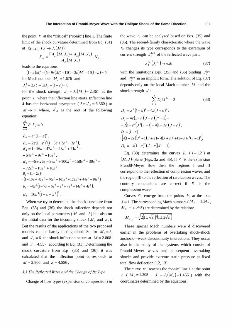
The relation Eq. (31) determines the geometric curvature of the interacting shock in an explicit form though this formula can not be applied to the shock with the subsonic flow downstream. In the critical case ( ( )MJJ *= , 1→M
) ) the shock curvature is finite, and Eq. (31) with the coefficients iA2 computed at
( )MJJ *= confirms it. As it follows from Eq. (31), rather strong shocks
interacting with the expansion wave are convex downwards (for example, the section BE of the shock in Fig. 1b). The loss of the shock strength under the further influence of the expansion wave leads to shock inflection, and the curvature becomes negative (such is the section EC ). The negative curvature of the shock degenerating inside the expansion fan into a weak discontinuity as shown in Fig. 1a asymptotically strives to zero. If the shock interacts with the compression wave, the sign of its curvature changes in a reverse order.
The location of the shock inflection point is determined by Eq. (31) at the condition 0=σK . The shock curvature direction changes when shock parameters cross curve 4 in Fig. 3a. Curve 4 goes out
The Interaction of Prandtl-Meyer Wave with the Oblique Shock of the Same Direction
131
the point r at the “critical” (“sonic”) line 1. The finite limit of the shock curvature determined from Eq. (31) at 1→M
) ( ( )MJJ *→ ): ( ) ( )
( ) 2*25
*22*21
,,,
NJMA
JMAJMAK ⋅
+Γ=σ
leads to the equations ( ) ( ) ( ) ( ) 01162112951 246 =−−−+−−− εεεε rrr MMM
for Mach number 676.1=rM and ( ) 0132 23 =−−−− εε rrr JJJ
for the shock strength ( ) 361.2* == rr MJJ at the point r where the inflection line starts. Inflection line 4 has the horizontal asymptote ( 360.6== AJJ ) at
∞→M where, AJ is the root of the following equation:
06
0
=∑=i
iAi JB ,
( )426 1 εε −=B ,
( ) ( )3225 335112 εεεεε −+−−=B ,
,16964714847161
765
4324
εεε
εεεε
++−
−+−+−=B
,161672
3015810036266876
54323
εεε
εεεεε
+−−
−−−+−+−=B
( )( ),16441221614042101
21765432
2
εεεεεεε
ε
++++++−⋅
⋅−=B
( )6543221 41476718 εεεεεεε +++−+−−=B ,
( )2240 116 εεε −−=B .
When we try to determine the shock curvature from Eqs. (35) and (36), the shock inflection depends not only on the local parameters ( M and J ) but also on the initial data for the incoming shock ( 1M and 2J ). But the results of the applications of the two proposed models can be barely distinguished. So for 31 =M and 62 =J the shock inflection occurs at 808.2=M and 557.4=J according to Eq. (31). Determining the shock curvature from Eqs. (35) and (36), it was calculated that the inflection point corresponds to
806.2=M and 556.4=J .
3.3 The Reflected Wave and the Change of Its Type
Change of flow types (expansion or compression) in
the wave 3r can be analyzed based on Eqs. (35) and (36). The second-family characteristic where the wave
3r changes its type corresponds to the extremum of current strength ( )ϕ
3J of the reflected wave part:
( ) ( )( ) extr13 →ϕϕ JJ (37)
with the limitations Eqs. (35) and (36) binding ( )ϕ1J
and ( )ϕ3J in an implicit form. The solution of Eq. (37)
depends only on the local Mach number M and the shock strength J :
03
0
2 =∑=i
ii MD (38)
( ) ( )2223 41 εεε +−+= JJD ,
( )( )( )( ) ( ) ( )( ) ,214112
114222
22
εεε
εεε
+−−−−−
−−+−=
JJJ
JJD
( )( )( )( ) ( ) ( ) ( )[ ],1141214
12222
1
−−++++−−⋅
⋅−=
JJJJJ
D
εεεε
ε
( ) ( )( )114 220 −+−−= JJD εε .
Eq. (38) determines the curves iϕ ( 2,1=i ) at ( )JM , -plane (Figs. 3a and 3b). If 1r is the expansion Prandtl-Meyer flow then the regions I and II correspond to the reflection of compression waves, and the region III to the reflection of rarefaction waves. The contrary conclusions are correct if 1r is the compression wave.
Curves iϕ emerge from the points iF at the axis 1=J . The corresponding Mach numbers ( 245.1
1=FM ,
540.22
=FM ) are determined by the relation:
( ) ( )εε 21122,1
±±=FM
These special Mach numbers were d discovered earlier in the problems of overtaking shock-shock anshock—weak discontinuity interactions. They occur also in the study of the systems which consist of Prandtl-Meyer waves and subsequent overtaking shocks and provide extreme static pressure at fixed total flow deflection [12, 13].
The curve 1ϕ reaches the “sonic” line 1 at the point s ( 305.1=sM , ( ) 466.1* == ss MJJ ) with the coordinates determined by the equations:

The Interaction of Prandtl-Meyer Wave with the Oblique Shock of the Same Direction
132
( )( ) ( ) ,01166814
9234222
426
=−−+−+
+−++
εεε
εεε
s
ss
M
MM
( ) ( )( ) .031
52513432
2223
=−−−+
++−−−+
εεε
εεεε sss JJJ
The coordinates ( 089.2=uM , 989.1=uJ ) of the point u where the curve 2ϕ has a vertical tangent are determined by more complex expressions (for example,
( )εuJ can be presented as a root of an eighth-order algebraic equation). To find out its coordinates it is easier to solve the system which consists Eq. (38) and the following equation:
03
0
2 =∑=i
iui ME ,
( ) 223 812 εε −−= JE ,
( ) ( ) ( )( )εεεεεε 5322412132 32222 −++−−+−−= JJE ,
( )( ) ( ) ( )( ) ( )[ ],41285131312
1223
1
εεεεε
ε
−−+−+−+−⋅
⋅−=
JJJE
( ) ( )220 32114 JJE −−−= εε .
As it is seen in Fig. 3a, one of the integral curves of Eq. (32) has point v of contact with the curve 2ϕ . To achieve its coordinates ( 282.2=vM , 434.3=vJ ), we have to equate the slopes of the curve 2ϕ and the integral curve of Eq. (32). The thick integral curve 5 of Eq. (32) descending from the point ( 670.2=M ,
( ) 440.6* == MJJ ) at the “sonic” line 1 to the point ( 477.1=M , 1=J ) contacted the curve 2ϕ at the point v . All the integral curves situated to the right of curve 5 correspond to at least one reflected wave type change point.
The curve 2ϕ asymptotically reaches the line 12 −= MJ at ∞→M .
Using the “differential” curved shock model Eqs. (31) or (32) and differential conditions (25) of the dynamic compatibility at the interacting shock as well as Eqs. (14) and (15) we went to the following correlation of flow non-uniformities upstream and downstream the shock:
( ) ( )[ ]252151
12112522211521
2
2
1
1
ACACAAAAAACC
NN
NN
Γ++Γ−+Γ
−=
==
)
))
(39)
We have to note the following correlation of the basic non-uniformities immediately after every inner point of the curved shock:
021 =Γ+ NN)))
(40)
which is analogous to the relation correct everywhere inside Prandtl-Meyer wave 3r . The Eq. (40) is the special case of generalized Chester-Whitham theorem proven in Ref. [8].
Analyzing Eq. (39) for 01 =N) , we transformed it to
the same Eq. (38) which was achieved earlier concerning wave 3r change of type. The coincidence of the solutions subsequent to “differential” model (for the points situated immediately after the shock) and “integral” model (for the reflected wave) reveals that the flow type seems not to change along the second-family reflected characteristics, even in zone 5.
Flow type change in the reflected wave can be illustrated by the influence of the expansion wave on the shock with initial “sonic” strength
282.8*2 == JJ at 31 =M (the integral curve 1KK in Fig. 3). The sector 2KK of this curve corresponds to the flow expansion in the reflected wave (from
12 =M to ( ) 0208.13 =ϕM ). The flow compression in the reflected wave begins at 860.2=M and
543.6=J (point 2K ). Shock inflection point 3K ( 572.2=M , 258.4=J ) is situated in this sector. The Mach number in the reflected wave diminishes to
( ) 0007.13 =ϕM at the end of the compression sector 42 KK ( 089.2=M and 016.2=J at point 4K ).
But the flow at the reflected compression wave does not decelerate to the critical speed because the new expansion sector begins after the point 4K till the very shock degeneration into the weak discontinuity ( 1→J at 630.1=M ; point 1K ). The Mach number in the reflected wave strives there to 0016.1 , and the integral strength 3J of the reflected wave strives to 9981.0 . The change of the reflected wave type under the influence of the compression wave on the oblique shock occurs in an inverse order.
Comparing the data on the reflected wave obtained here with the analytical results in Ref. [13] where the
The Interaction of Prandtl-Meyer Wave with the Oblique Shock of the Same Direction
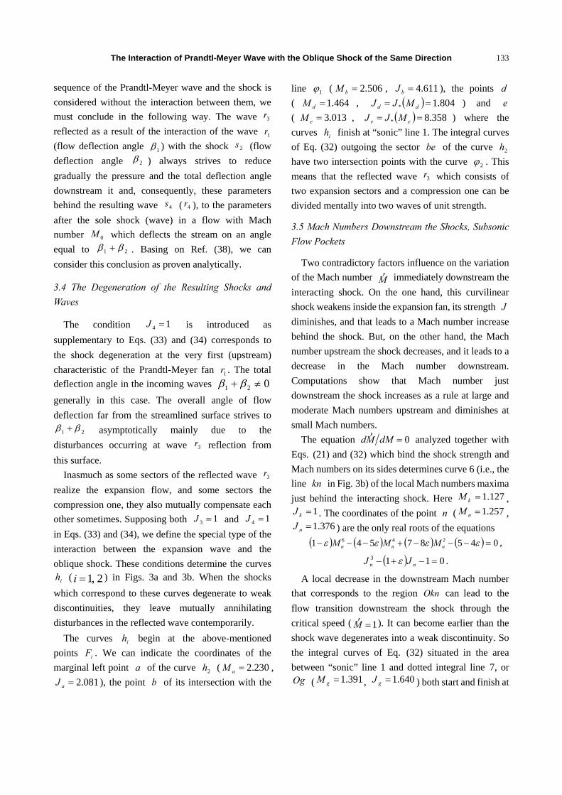
133
sequence of the Prandtl-Meyer wave and the shock is considered without the interaction between them, we must conclude in the following way. The wave 3r reflected as a result of the interaction of the wave 1r (flow deflection angle 1β ) with the shock 2s (flow deflection angle 2β ) always strives to reduce gradually the pressure and the total deflection angle downstream it and, consequently, these parameters behind the resulting wave 4s ( 4r ), to the parameters after the sole shock (wave) in a flow with Mach number 0M which deflects the stream on an angle equal to 21 ββ + . Basing on Ref. (38), we can consider this conclusion as proven analytically.
3.4 The Degeneration of the Resulting Shocks and Waves
The condition 14 =J is introduced as supplementary to Eqs. (33) and (34) corresponds to the shock degeneration at the very first (upstream) characteristic of the Prandtl-Meyer fan 1r . The total deflection angle in the incoming waves 021 ≠+ ββ generally in this case. The overall angle of flow deflection far from the streamlined surface strives to
21 ββ + asymptotically mainly due to the disturbances occurring at wave 3r reflection from this surface.
Inasmuch as some sectors of the reflected wave 3r realize the expansion flow, and some sectors the compression one, they also mutually compensate each other sometimes. Supposing both 13 =J and 14 =J in Eqs. (33) and (34), we define the special type of the interaction between the expansion wave and the oblique shock. These conditions determine the curves
ih ( 1, 2=i ) in Figs. 3a and 3b. When the shocks which correspond to these curves degenerate to weak discontinuities, they leave mutually annihilating disturbances in the reflected wave contemporarily.
The curves ih begin at the above-mentioned points iF . We can indicate the coordinates of the marginal left point a of the curve 2h ( 230.2=aM ,
081.2=aJ ), the point b of its intersection with the
line 1ϕ ( 506.2=bM , 611.4=bJ ), the points d ( 464.1=dM , ( ) 804.1* == dd MJJ ) and e ( 013.3=eM , ( ) 358.8* == ee MJJ ) where the curves ih finish at “sonic” line 1. The integral curves of Eq. (32) outgoing the sector be of the curve 2h have two intersection points with the curve 2ϕ . This means that the reflected wave 3r which consists of two expansion sectors and a compression one can be divided mentally into two waves of unit strength.
3.5 Mach Numbers Downstream the Shocks, Subsonic Flow Pockets
Two contradictory factors influence on the variation of the Mach number M
) immediately downstream the interacting shock. On the one hand, this curvilinear shock weakens inside the expansion fan, its strength J diminishes, and that leads to a Mach number increase behind the shock. But, on the other hand, the Mach number upstream the shock decreases, and it leads to a decrease in the Mach number downstream. Computations show that Mach number just downstream the shock increases as a rule at large and moderate Mach numbers upstream and diminishes at small Mach numbers.
The equation 0=dMMd)
analyzed together with Eqs. (21) and (32) which bind the shock strength and Mach numbers on its sides determines curve 6 (i.e., the line kn in Fig. 3b) of the local Mach numbers maxima just behind the interacting shock. Here 127.1=kM ,
1=kJ . The coordinates of the point n ( 257.1=nM , 376.1=nJ ) are the only real roots of the equations
( ) ( ) ( ) ( ) 04587541 246 =−−−+−−− εεεε nnn MMM ,
( ) 0113 =−+− nn JJ ε .
A local decrease in the downstream Mach number that corresponds to the region Okn can lead to the flow transition downstream the shock through the critical speed ( 1=M
) ). It can become earlier than the shock wave degenerates into a weak discontinuity. So the integral curves of Eq. (32) situated in the area between “sonic” line 1 and dotted integral line 7, or Og ( 391.1=gM , 640.1=gJ ) both start and finish at

The Interaction of Prandtl-Meyer Wave with the Oblique Shock of the Same Direction
134
the “sonic” line (to the right of point g and to the left of it, correspondingly). Considering only the supersonic flow downstream the shock, we can conclude that the integral curve starting from point n finishes at the same point at once.
When the shock 2j interacts with the preceding expansion wave 1r , the shock strength diminishes, and full pressure losses at the interacting shock become smaller. The Mach number immediately behind the interacting shock is always larger than the Mach number at the corresponding characteristic of the reflected wave. So, when the flow immediately after the shock sometimes decelerates to a critical and even subsonic velocity, it means that the supersonic flow in the reflected mainly compression wave 3r have decelerated to the critical velocity sooner.
According to the model Eqs. (33) and (34), the critical flow deceleration in the reflected compression wave is possible for incoming shocks which correspond to the dashed regions “A” and “B” adjacent to the curves a8 (Fig. 3b) and b8 (Fig. 3a) if the incoming expansion wave 1r is strong enough. Points d and e at the “sonic” line whose coordinates are calculated in Subsection 3.4 ( 464.1=dM ,
013.3=eM ) are the endpoints of “A” and “B” regions, correspondingly. The region of possible flow deceleration immediately downstream the shock bounded by the integral curve Og and “sonic” line 1 is situated inside the region “A” of flow deceleration in the reflected wave.
Possible solutions for the strong incoming shocks (at ( ) ( )MJJMJ m<< 21* , so 12 <M , Fig. 1d) ignore the influence of the other disturbances from the subsonic flow downstream the shock to this one. So it seems that the solutions for the strong shocks cannot be mentioned here due to their low practical importance.
3.5 The Influence of Gas Specific Heats Ratio on the Problem Solution
To characterize the influence of specific heats ratio
on the solutions derived here, it seems enough to study the variation of the special curves and the points plotted above.
Starting points iF of the curves iϕ merge at 1→γ ( 2
21== FF MM then). A distance between
these curves increases with the growth of γ . So the region II which corresponds to the expansion wave reflection at shock interaction with incoming expansion wave widens then.
The first of the start points iF moves to smaller Mach numbers region (so 245.1
1=FM at 4.1=γ ,
189.11
=FM at 3=γ , 321
→FM at ∞→γ ). The same is correct for the whole 1ϕ ( sF1 ) line (so
318.1→sM and 434.1→sJ at 1→γ ; 305.1=sM and 466.1=sJ at 4.1=γ ; 288.1=sM and 529.1=sJ at 3=γ ; 272.1→sM
and 618.1→sJ at ∞→γ ). So region I where the reflected wave 3r is of another type than incoming wave 1r becomes narrower.
The curve kn of the maximum downstream Mach numbers also exists at all ∞<< γ1 moving a little to the larger Mach numbers (so 253.1→nM and
325.1→nJ at 1→γ ; 257.1=nM and 376.1=nJ at 4.1=γ ; 263.1=nM and 567.1=nJ
at 3=γ ; 272.1→nM and 618.1→nJ at ∞→γ ). Points n and s coincide at ∞→γ .
Another reflected wave type change curve 2ϕ moves sufficiently to the right. So the coordinates of its extreme left point u are the following: 790.1=uM and 436.1=uJ at 2.1=γ ; 089.2=uM and
989.1=uJ at 4.1=γ ; 539.2=uM and 980.2=uJ at 66.1=γ . The Mach number
2FM also increases ( 876.1
2=FM at 2.1=γ , 540.2
2=FM at 4.1=γ ,
325.162
=FM at 66.1=γ ) and strives to infinity at 35=γ . The lower branch of the curve 2ϕ has a
horizontal asymptote ( 1=J ) in the last case. The further increase of the specific heats ratio leads to a corresponding shift of the curve 2ϕ to the right (so
027.6=uM and 098.16=uJ at 3=γ ; ∞→uM and ∞→uJ at ∞→γ ). The curve 2h and the region b3 corresponding to shock degeneration and

The Interaction of Prandtl-Meyer Wave with the Oblique Shock of the Same Direction
135
critical flow deceleration in the reflected waves also shift to the right. The rules determining the direction of shock curvature remain the same for other γ ’s. Mach numbers and shock strengths corresponding to the shock inflection increase a little: for example,
659.1→rM and 206.2→rJ at 1→γ ; 676.1=rM and 361.2→rJ at 4.1=γ ; 3→rM and 3→rJ at ∞→γ . The inflection
curve 2 always has the horizontal asymptote AJJ = (e.g., 061.13→AJ at ∞→γ ).
So the increase in specific heats ratio widens the expansion wave reflection region (as 1r is the expansion wave) and shifts the majority of the special curves and points plotted here to the region of larger Mach numbers and shock strengths.
The dependence of some specific Mach numbers upon the specific heats ratio in the practically important range ( 21 << γ ) is shown in Fig. 5. One can see, for example, that some specific small Mach numbers ( kM ,
nM , sM , gM , dM , rM ) are weakly dependent on γ in the range shown there.
4. Conclusions
Owing to the expressions derived for the differential parameters of Prandtl-Meyer flowfield and the
Fig. 5 Variation of the specific Mach numbers in the practically important range of γ ’s. According to the citation order: rM (curve 1), 1FM and 2FM (curves 2 and 3, correspondingly), sM (curve 4), uM (5), vM (6),
aM (7), bM (8), dM (9), eM (10), kM (11), nM (12) and gM (13).
differential dynamic compatibility conditions on a curved shock in a generally non-uniform flow, two reliable analytical solutions for overtaking Prandtl-Meyer wave—oblique shock interaction were obtained.
When used together, these solutions allows us to estimate both the flow parameters and their spatial derivatives downstream the shock as well as the distinctive features of the interacting shock and reflected Prandtl-Meyer wave. So the geometrical curvature and the inflection points at the interacting shock were determined analytically, in particular.
A simple expression determining the rarefaction/compression flow type change immediately behind the shock as well as in the reflected wave was derived also. It was proven that the reflected Prandtl-Meyer wave can change its type, not once somewhere. The criteria of the full mutual compensation of the different sectors of the reflected wave and the criteria of the shock degeneration were also derived and studied.
Non-monotonic variation of the Mach numbers just downstream the curvilinear interacting shock was discovered, and the possibility of subsonic flow pockets was revealed. The influence of the ratio of gas specific heats on the deduced solutions was found more quantitative than qualitatively remarkable.
The most evident applications of the presented results are: the optimal design of supersonic inlets; the design of optimally shaped aerodynamic bodies for supersonic flight; the analysis of supersonic jet technology apparatus because of the sequential interchange of compression and expansion flow regions divided by the shocks in the “barrels” of supersonic jet flows.
References
[1] R. Courant, K.O. Friedrichs, Supersonic Flow and Shock Waves, Wiley Interscience, New York, 1948.
[2] A.L. Adrianov, A.L. Starykh, V.N. Uskov, Interaction of Stationary Gas-Dynamic Discontinuities, Novosibirsk, Nauka, 1995. (in Russian)
[3] V.N. Uskov, M.V. Chernyshov, Conjugation of Prandtl-Meyer wave with quasi-one-dimensional flow
The Interaction of Prandtl-Meyer Wave with the Oblique Shock of the Same Direction
136
region, Mathematical Modeling 15 (6) (2003) 111-119. (in Russian)
[4] G. Emanuel, H. Hekiri, Vorticity jump across a shock in nonuniform flow, Shock Waves 21 (1) (2011) 71-72.
[5] G. Emanuel, H. Hekiri, Vorticity and its rate of change just downstream of a curved shock, Shock Waves 17 (1-2) (2007) 85-94.
[6] A.V. Omelchenko, On the correlation of derivatives at a strong discontinuity, Computational Mathematics and Mathematical Physics 42 (8) (2002) 1246-1257. (in Russian)
[7] M.V. Chernyshov, The Interactions of the Elements of Shock-Wave Systems Between Themselves and with Different Surfaces, Ph.D. Thesis, Saint Petersburg, Baltic State Technical University, 2002. (in Russian)
[8] A.V. Omelchenko, The generalized Chester-Whitham invariant, Technical Physics Letters 27 (11) (2001) 891-893.
[9] A.L. Adrianov, A Model of the Flow Downstream the Curvilinear Stationary Shock, Krasnoyarsk, Computational Center of RAS Siberian Branch, 1997. (in Russian)
[10] H. Li, G. Ben-Dor, Oblique Shock—Expansion Fan Interaction—Analytical Solution, AIAA Journal 43 (2) (1996) 418-421.
[11] V.R. Meshkov, A.V. Omelchenko, V.N. Uskov, The interaction of the stationary shock with the expansion wave of opposite direction, Vestnik Saint Petersburg University: Mathematics 2 (9) (2002) 99-106. (in Russian)
[12] A.V. Omelchenko, V.N. Uskov, An optimal shock-expansion system in a steady gas flow, Journal of Applied Mechanics and Technical Physics 38 (3) (1997) 204-210.
[13] A.V. Omelchenko, V.N. Uskov, Optimum overtaking compression shocks with restriction imposed on the total flow-deflection angle, Journal of Applied Mechanics and Technical Physics 40 (4) (1999) 638-646.