Embed Size (px)
Citation preview
Proc. of the 13th Int. Conference on Digital Audio Effects (DAFx-10), Graz, Austria , September 6-10, 2010
THE JAMOMA AUDIO GRAPH LAYER
Timothy Place
74 Objects LLC,Kansas City, Missouri, [email protected]
Trond Lossius
BEK - Bergen Center for Electronic ArtsBergen, Norway
Nils Peters
McGill University, CIRMMTMontreal, Quebec, Canada
ABSTRACT
Jamoma Audio Graph is a framework for creating graph struc-tures in which unit generators are connected together to processdynamic multi-channel audio in real-time. These graph structuresare particularly well-suited to spatial audio contexts demandinglarge numbers of audio channels, such as Higher Order Ambison-ics, Wave Field Synthesis and microphone arrays for beamform-ing. This framework forms part of the Jamoma layered architec-ture for interactive systems, with current implementations of Ja-moma Audio Graph targeting the Max/MSP, PureData, Ruby, andAudioUnit environments.
1. INTRODUCTION
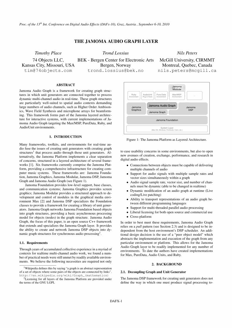
Many frameworks, toolkits, and environments for real-time au-dio fuse the issues of creating unit generators with creating graphstructures1 that process audio through those unit generators. Al-ternatively, the Jamoma Platform implements a clear separationof concerns, structured in a layered architecture of several frame-works [1]. Six frameworks currently comprise the Jamoma Plat-form, providing a comprehensive infrastructure for creating com-puter music systems. These frameworks are: Jamoma Founda-tion, Jamoma Graphics, Jamoma Modular, Jamoma DSP, JamomaGraph and Jamoma Audio Graph (see Figure 1).
Jamoma Foundation provides low-level support, base classes,and communication systems; Jamoma Graphics provides screengraphics; Jamoma Modular provides a structured approach to de-velopment and control of modules in the graphical media envi-ronment Max [2] and Jamoma DSP specializes the Foundationclasses to provide a framework for creating a library of unit gener-ators. Jamoma Graph networks Jamoma Foundation based objectsinto graph structures, providing a basic asynchronous processingmodel for objects (nodes) in the graph structure. Jamoma AudioGraph, the focus of this paper, is an open source C++ frameworkthat extends and specializes the Jamoma Graph layer. It providesthe ability to create and network Jamoma DSP objects into dy-namic graph structures for synchronous audio processing2.
1.1. Requirements
Through years of accumulated collective experience in a myriad ofcontexts for realtime multi-channel audio work, we found a num-ber of practical needs were still unmet by readily available environ-ments. We believe the following necessities are required not only
1Wikipedia defines this by saying “a graph is an abstract representationof a set of objects where some pairs of the objects are connected by links”.http://en.wikipedia.org/wiki/Graph_(mathematics)
2Licensing for all layers of the Jamoma Platform are provided underthe terms of the GNU LGPL
Jamoma Modular
Max/MSPEnvironment
RubyEnvironment
Jamoma Foundation
AudioUnitPlug-in Hosts
Pure DataEnvironment
System Layer(Mac OS, Windows, PortAudio, Cairo, etc.)
...
Jamoma Audio Graph Jamoma
DSPJamoma Graphics
Jamoma Graph
Figure 1: The Jamoma Platform as Layered Architecture.
to ease usability concerns in some environments, but also to opennew avenues of creation, exchange, performance, and research indigital audio effects.
• Connections between objects must be capable of deliveringmultiple channels of audio
• Support for audio signals with multiple sample rates andvector sizes simultaneously within a graph
• Audio signal sample rate, vector size, and number of chan-nels must be dynamic (able to be changed in realtime)
• Dynamic modification of an audio graph at runtime (Livecoding/Live patching)
• Ability to transport representations of an audio graph be-tween different programming languages
• Support for multi-threaded parallel audio processing• Liberal licensing for both open source and commercial use• Cross-platform
In order to best meet these requirements, Jamoma Audio Graphrelies on a pull pattern (see Section 2.3) and is designed to be in-dependent from the host environment’s DSP scheduler. An addi-tional design decision is the use of a “peer object model" whichabstracts the implementation and execution of the graph from anyparticular environment or platform. This allows for the JamomaAudio Graph layer to be readily implemented for any number ofenvironments. To date the authors have created implementationsfor Max, PureData, Audio Units, and Ruby.
2. BACKGROUND
2.1. Decoupling Graph and Unit Generator
The Jamoma DSP framework for creating unit generators does notdefine the way in which one must produce signal processing to-
DAFX-1
Proc. of the 13th Int. Conference on Digital Audio Effects (DAFx-10), Graz, Austria , September 6-10, 2010
pographies. Instead, the process of creating objects and connectingthem are envisioned and implemented orthogonally. The graph iscreated using a separate framework: Jamoma Audio Graph. Due tothis decoupling of Jamoma DSP and Jamoma Audio Graph we areable to create and use Jamoma DSP unit generators with a numberof different graph structures. Jamoma Audio Graph is one graphstructure that a developer may choose to employ.
Common real-time audio processing environments includ-ing Max/MSP, Pd, SuperCollider, Csound, Bidule, AudioMulch,Reaktor and Reason all have unit generators, but the unit genera-tors can only be used within the particular environment. The unitgenerators have a proprietary format and thus no interchangeabil-ity. Likewise, the graph structure is proprietary. While SDKs areavailable for some of these environments, for others no SDK existsand the systems are closed. Ability to host Audio Units and VSTmay extend these environments, but with limitations.
2.2. Audio Graph Structures
A graph structure is an abstract structure where paths are createdbetween nodes (objects) in a set. The paths between these nodesthen define the data-flow of the graph. Graph structures for audiosignal processing employ several patterns and idioms to achieve abalance of efficiency, flexibility, and real-time capability.
Environments for real-time processing typically need to ad-dress concerns in both synchronous and asynchronous contexts.Asynchronous communication is required for handling MIDI,mouse-clicks and other user interactions, the receipt of OpenSound Control messages from a network, and often for drivingattributes from audio sequencer automations. Conversely, realtimeprocessing of audio streams must be handled synchronously. Mostenvironments, such as CLAM [3], deal with these two types ofgraphs as separate from each other. In the Jamoma Platform thisis also the case, where Jamoma Audio Graph comprises the syn-chronous audio graph concerns, and Jamoma Graph implementsasynchronous message passing.
To reduce the computational overhead of making synchronouscalls through the graph for every sample, most systems employthe notion of frame processing. The TTAudioSignal class inJamoma DSP represents audio signals as a collection of audio sam-ple vectors and metadata, containing one vector per audio channel.Jamoma Audio Graph uses the TTAudioSignal class to pro-cesses these vectors of samples at once rather than a single sampleat a time.
2.3. Push vs. Pull
When visualizing a signal processing graph, it is common to rep-resent the flow of audio from top-to-bottom or left-to-right. Underthe hood, the processing may be implemented in this top-to-bottomflow as well. Audio at the top of the graph ‘pushes’ down througheach subsequent object in the chain until it reaches the bottom.
Alternatively, audio processing may be driven from the bottomof the chain from a ‘terminal object’ or ‘sink’. This strategy forprocessing an audio graph, the ‘pull’ method, is used by several en-vironments including Apple’s AUGraph and ChucK [4]. AUGraphand ChucK are subject to certain limitations however: AUGraphdoes not permit “fanning” connections (many inlets connected toone outlet)3 while ChucK is not multi-threaded.
3http://developer.apple.com/mac/library/documentation/General/Conceptual/SLGlobalGlossary/Glossary/Glossary.html
2.4. Multi-channel Processing
In many real-time audio patching environments, such asMax/MSP, Pd, Bidule or AudioMulch, audio objects are connectedusing mono signals. For multi-channel spatial processing the patchhas to be tailored to the number of sources and speakers. If suchprograms are considered programming environments and the patchthe program, a change in the number of sources or speakers re-quires a rewrite of the program, not just a change to one or moreconfiguration parameters.
2.4.1. CSound
In Csound multi-channel audio graph possibilities are extendedsomewhat through the introduction of the “chn” set of opcodes.The “chn” opcodes provide access to a global string-indexed soft-ware bus enabling communicating between a host application andthe Csound engine, but can also be used for dynamic routingwithin Csound itself [5]. Below is an example of a simple multi-channel filter implementation using named software busses to iter-ate through the channels:
multi-channel filter, event handlerinstr 2iNumC = p4 ; number of channelsiCF = p5 ; filter cutoffichnNum = 0 ; init the channel number
makeEvent:ichnNum = ichnNum + 1event_i "i", 3, 0, p3, ichnNum, iCFif ichnNum < iNumC igoto makeEventendin
multi-channel filter, audio processinginstr 3instance = p4iCF = p5Sname sprintf "Signal_%i", instancea1 chnget Snamea1 butterlp a1, iCF
chnset a1, Snameendin
2.4.2. SuperCollider
SuperCollider employs an elegant solution by representing signalscontaining multiple channels of audio as arrays. When an arrayof audio signals is given as input to a unit generator it causesmulti-channel expansion: multiple copies of the unit generator arespawned to create an array of unit generators, each processing adifferent signal from the array of inputs. In the following examplea stereo signal containing white and pink noise is filtered:
{\\ Create stereo signal as array:p = [WhiteNoise.ar, PinkNoise.ar];
\\ Biquad filter applied to array of channels:SOS.ar(p, 1, -1.992, 0.986, 1.992, -0.993, 0.1);
}.play
DAFX-2
Proc. of the 13th Int. Conference on Digital Audio Effects (DAFx-10), Graz, Austria , September 6-10, 2010
3. DESIGN AND IMPLEMENTATION
3.1. Structure
Jamoma Audio Graph is a framework4 implementing a syn-chronous multi-channel audio processing graph driven usinga pull methodology. This is accomplished through the cre-ation of a node class for the graph, TTAudioGraphObject,which wraps a unit generator with other supporting objects.TTAudioGraphObject then manages these instances and theinformation necessary to pull samples from its sources.
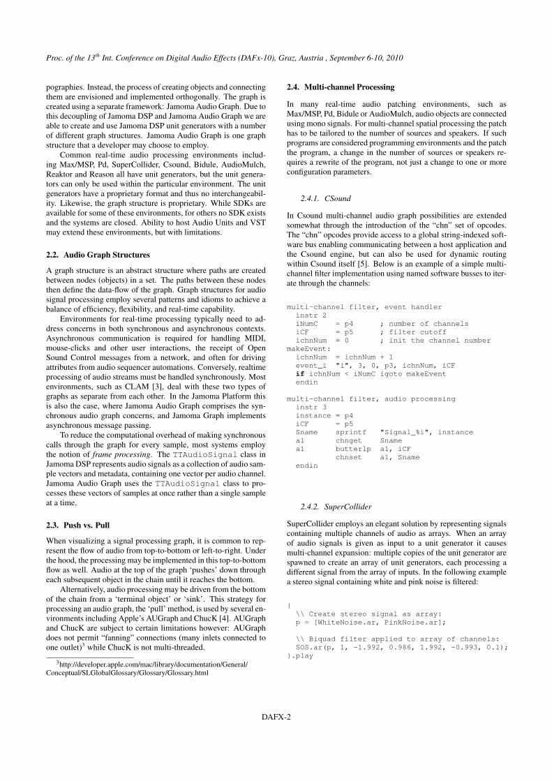
Figure 2 shows these classes and their relations. Here, an ob-ject is connected to three upstream objects, and to two downstreamobjects, with all connections being multi-channel. In database par-lance, a connection between objects can be considered as a many-to-many association; each outlet can be connected to many inlets,and each inlet can be connected to many outlets. The source ob-jects represented by s0, s1, etc. can then be considered as jointables representing each connection in the many-to-many relation-ship individually.
Unit Generator
out0 out1 out0 out1 out0
s0
in2
s0
in2
s0
in2
s0
in2
s1
in0
s0 s1
in1
s0
in2s0 s1 s2
in3
s0
out0 out1 out2 out3
Figure 2: TTAudioGraphObject Class Anatomy
The architecture of TTAudioGraphObject is layered: the au-dio graph object itself only knows about its inlets; the inlets onlyknow about their sources (the so-called ‘joins’ in database termi-nology); the sources know from what object and from which outletthey are connected. In the figure this is illustrated by the objecthaving four inlets. Two multi-channel sources s0 and s1 are con-nected to the first inlet in0, two to the second, and so on. In short:
A graph has many objects.An object has many inlets.An inlet has many sources.A source has many channels.
3.2. Building the Graph
For processing to occur, the connections of the graph must be es-tablished. This is accomplished by passing a reference to a sourceobject, as well as the outlet and inlet numbers for the connection,
4We use the term framework in a generic sense, as a dynamically linkedlibrary together with supporting source and an API.
to the downstream object’s connect() method. Similarly, con-nections may be cut by passing the same information to the down-stream object’s drop() method. Connections may be created ordropped at any time before, after or during the graph being pro-cessed. That is to say that there is no global signal chain compi-lation; the graph may dynamically change over the course of itsoperation and performance.
3.3. Processing the Graph
All processing is driven by the object at the end of the processingchain according to a two step process. First, a ‘preprocess’ methodis propagated up the chain from the terminal object. This zeroesbuffers and sets flags that indicate each object’s processing state.It is of no consequence if an object receives multiple preprocesscalls, such as would happen if there are multiple terminal nodes.
Since Jamoma Audio Graph is using a pull-based architecture,an object’s outlets are passive. They are simply buffers storing theoutput calculated by the wrapped unit generator. The unit gen-erator is simply an instance of a Jamoma DSP class, specified asan argument when the TTAudioGraphObject is instantiated.This unit generator is responsible for actually calculating the au-dio to be stored by the outlet buffers.
Unlike the outlets, the inlets are active. When asked for a vec-tor of audio by the unit generator, the inlets each request audiofrom each of their sources (other objects’ outlets). If an inlet hasmultiple sources, those sources are summed. When all of the inletshave performed this operation, then the unit generator proceeds toprocess the audio buffered in the inlets and fills the buffers in theoutlets. Sources manage a one-to-one connection between an inletand an outlet; inlets may have zero or more sources. To summa-rize:
With the objects in the graph prepared by thepreprocess() call, the audio can be pulled from thegraph by a terminal object using the process() call on each ofits sources.
3.4. Graph Description
Given an audio graph, the topology can be traversed for pur-poses other than directly calculating audio. Any node in an au-dio graph can be queried to create a description. The returnedTTAudioGraphDescription object will then provide meta-data about the entire graph as seen through that object’s inlets.There are many applications of this description, including visualrepresentation of the graph, statistical analysis, and cross-coding.
4. APPLICATION
4.1. Max/MSP
A number of externals for multi-channel audio processing in Maxhave been developed combining Jamoma’s Audio Graph and DSPframeworks. The Max implementation of the Jamoma AudioGraph layer represents multi-channel signals as ordinary patchchords. Interfacing between MSP and a Jamoma Audio Graph isfacilitated by the externals jcom.pack≈ and jcom.unpack≈, pack-ing and unpacking multiple mono MSP signals into and out ofa Jamoma Audio Graph multi-channel signal. jcom.adc≈ andjcom.dac≈ offer additional possibilities for direct audio input andoutput using PortAudio [6] and thus bypassing MSP altogether.Two or more multi-channel signals might be intertwined into one
DAFX-3
Proc. of the 13th Int. Conference on Digital Audio Effects (DAFx-10), Graz, Austria , September 6-10, 2010
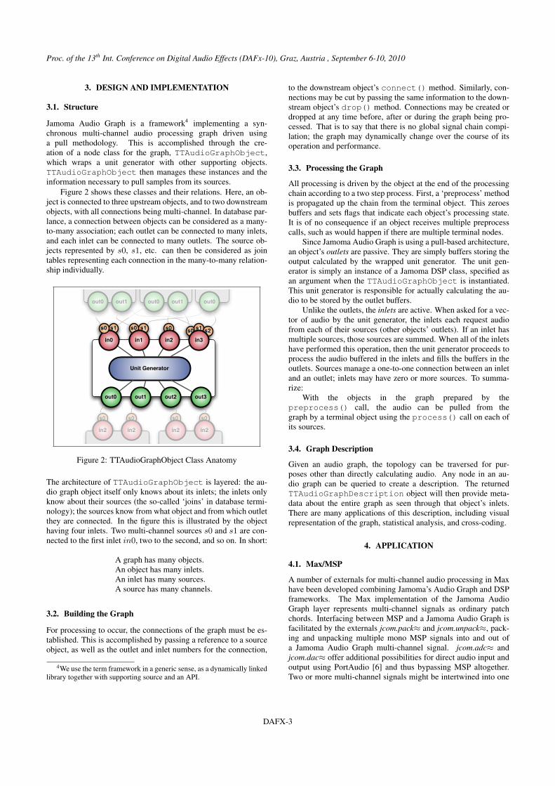
(a) Without Audio Graph, using MSP audio signals for 3 inputs and 16 loudspeakers (b) With Audio Graph
Figure 3: The Jamoma signal processing Max patch for Distance Based Amplitude Panning (DBAP)
joint multi-channel signal and separated again using jcom.join≈and jcom.split≈. The sample rate and vector size used for audiograph processing, as well as the number of channels in a multi-channel signal, can be inspected using jcom.info≈.
A number of multi-channel audio generators and processorscomprising common signal processing tasks are available. Thisset of generators can be readily extended. For example, the variousunits available in the Jamoma DSP libraries can be easily wrappedinto Audio Graph externals for Max using a single line of C++code.
Spectral processing for multi-channel signals is implementedthrough the jcom.fft≈ and jcom.window≈ objects. Severalobjects are available for level control and mixing, such asjcom.gain≈ for controlling gain levels of multi-channel signals,while jcom.matrix≈ allows M × N matrix-based mixing of theM channels of the incoming signal onto the N channels of theresulting signal. This can be used for various amplitude-basedspatialization algorithms such as VBAP [7], DBAP [8] and am-bisonics [9]. Finally jcom.matrixmixer≈ offers the possibility ofmixing M incoming multi-channel signals onto N returned multi-channel signals. This combined mixer/router is still rudimentary,and assumes all incoming and returned signal to have the samenumber of channels.
Figure 3 illustrates the use of Jamoma Audio Graph objects ina patch providing spatialization of 3 mono sources to 16 speakers,with additional post-spatialization mastering of the signals using alimiter and gain adjustment. The use of Jamoma Audio Graph ob-jects greatly helps simplifying the patch as compared to a standardMSP audio graph.
4.1.1. Jamoma Modular
A strong component of the Jamoma Modular framework is theprovision of ready-to-use building blocks for sound spatialization[10].
In the past Jamoma used a simple patching hack that wrappedmultiple MSP signals into a multi-channel cable. Within eachmodule, this multi-channel connection was then unwrapped in or-der that audio signals could be processed. One of several disad-vantages of this solution was that whenever the number of sourcesor speakers was changed, MSP objects and connections had to be
destroyed and created. Jamoma modules for spatialization requireflexibility to enable users to define the number of incoming sounds(to be spatialized) and the number of outgoing audio feeds (numberof loudspeakers), thus further requiring that creation and deletionof MSP objects and connections be done using patcher scripting.This creates stress on Max in time critical situations, and is notsufficiently reliable for real-world performance situations. Fur-thermore, a change in the DSP structure also requires a rebuildof the DSP chain.
The previous scripting and patching hack approach is currentlybeing replaced by Jamoma Audio Graph objects to simplify thespatialization modules and make them more robust. Figure 3b in-dicates how the number of sources and speakers can be changedsimply by updating attribute values for a few Jamoma Audio Graphobjects, thus eliminating the need for patcher scripting in JamomaModules. Because the Audio Graph signal network can be dynam-ically reconfigured without the need to recompile the DSP signalchain, on-the-fly changes are possible while audio is running. Inother words, a change to the number of channels requires only achange of parameters rather than change to the program itself.
4.2. PureData (Pd)
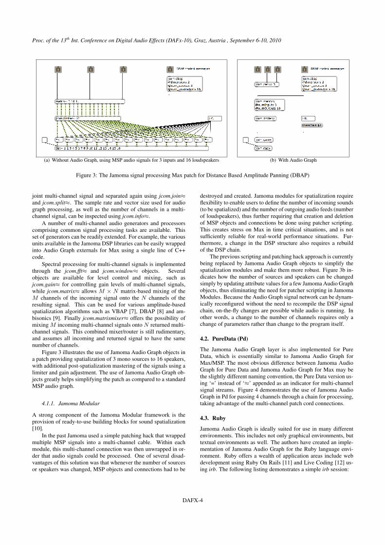
The Jamoma Audio Graph layer is also implemented for PureData, which is essentially similar to Jamoma Audio Graph forMax/MSP. The most obvious difference between Jamoma AudioGraph for Pure Data and Jamoma Audio Graph for Max may bethe slightly different naming convention, the Pure Data version us-ing ‘=’ instead of ‘≈’ appended as an indicator for multi-channelsignal streams. Figure 4 demonstrates the use of Jamoma AudioGraph in Pd for passing 4 channels through a chain for processing,taking advantage of the multi-channel patch cord connections.
4.3. Ruby
Jamoma Audio Graph is ideally suited for use in many differentenvironments. This includes not only graphical environments, buttextual environments as well. The authors have created an imple-mentation of Jamoma Audio Graph for the Ruby language envi-ronment. Ruby offers a wealth of application areas include webdevelopment using Ruby On Rails [11] and Live Coding [12] us-ing irb. The following listing demonstrates a simple irb session:
DAFX-4
Proc. of the 13th Int. Conference on Digital Audio Effects (DAFx-10), Graz, Austria , September 6-10, 2010
Figure 4: Pd patch, processing 4 channels with Jamoma AudioGraph
require ’TTRuby’dac = TTAudio.new "dac"osc = TTAudio.new "wavetable"dac.connect_audio oscdac.send "start"osc.set "frequency", 220.0
By using Jamoma Audio Graph in the Ruby environment for livecoding, users are able to access all of the benefits of using a popu-lar, general purpose language (Ruby) while at the same time gain-ing access to many of the benefits of a domain specific languagefor musical performance (Jamoma DSP).
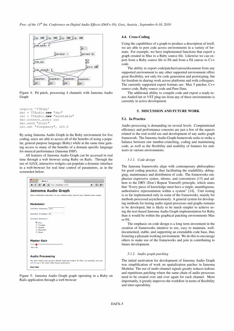
All features of Jamoma Audio Graph can be accessed in realtime through a web browser using Ruby on Rails. Through theuse of AJAX, interactive widgets can populate a dynamic interfacein a web-browser for real time control of parameters, as in thescreenshot below.
Figure 5: Jamoma Audio Graph graph operating in a Ruby onRails application through a web browser
4.4. Cross-Coding
Using the capabilities of a graph to produce a description of itself,we are able to port code across environments in a variety of for-mats. For example, we have implemented functions that export agraph created in Max to a Ruby source file. Likewise we can ex-port from a Ruby source file to Pd and from a Pd canvas to C++code.
The ability to export code/patcher/canvas/document from anysupported environment to any other supported environment offersgreat flexibility, not only for code generation and prototyping, butfor freedom in sharing work across platforms and with colleagues.The currently supported export formats are: Max 5 patcher, C++source code, Ruby source code and Pure Data.
The additional ability to compile code and export a ready-to-use AudioUnit or VST plug-ins from any of these environments iscurrently in active development.
5. DISCUSSION AND FUTURE WORK
5.1. In Practice
Audio processing is demanding on several levels. Computationalefficiency and performance concerns are just a few of the aspectsrelated to the real-world use and development of any audio graphframework. The Jamoma Audio Graph framework seeks to strike abalance between raw number-crunching, coding and maintainingcode, as well as the flexibility and usability of features for end-users in various environments.
5.1.1. Code design
The Jamoma frameworks align with contemporary philosophiesfor good coding practice, thus facilitating the readability, debug-ging, maintenance and distribution of code. The frameworks em-phasize expressive syntax, idioms, and conventions [13] and ad-here to the DRY (Don’t Repeat Yourself) principle, which statesthat “Every piece of knowledge must have a single, unambiguous,authoritative representation within a system” [14]. Unit testingis so far implemented only in some of the frameworks, mainly formethods processed asynchronously. A general system for develop-ing methods for testing audio signal processes and graphs remainsto be developed, but is likely to be much simpler to achieve us-ing the text-based Jamoma Audio Graph implementation for Rubythan it would be within the graphical patching environments Maxor Pd.
The emphasis on code design is a long term investment in thecreation of frameworks intuitive to use, easy to maintain, well-documented, stable, and supporting an extendable code base, thusfostering a pleasant working environment. We do this to encourageothers to make use of the frameworks and join in contributing tofuture development.
5.1.2. Audio graph patching
The initial motivation for development of Jamoma Audio Graphwas simplification of work on spatialization patches in JamomaModular. The use of multi-channel signals greatly reduces tediousand repetitious patching where the same chain of audio processesneed to be created over and over again for each channel. Moreimportantly, it greatly improves the workflow in terms of flexibilityand inter-operability.
DAFX-5
Proc. of the 13th Int. Conference on Digital Audio Effects (DAFx-10), Graz, Austria , September 6-10, 2010
Jamoma modules for spatialization share a common interface.The number of sources and speakers are dynamically reconfiguredon-the-fly using simple configuration scripts describing the num-ber and positions of sources and speakers. The usefulness of thiscan be illustrated by the practical experience of one of the au-thors while working on a sound installation in Oslo in 2002 asreported in [15]: For the final week preceding the opening, two ofthe composers moved several times a day between working at the24 speaker setup of the installation site, a 16 speaker setup at a stu-dio and off-site development using stereo headphones [16]. Eachtime a composer moved between environments the various parts ofthe patch dealing with spatialization had to be substituted. UsingJamoma Modular it would instead be possible to trigger simple cuescripts to reconfigure the system from one setup to another.
Within Jamoma Modular, Jamoma Audio Graph is eventuallyplanned to be used for all audio modules. One of the major benefitswill be the ability to easily reconfigure each module for work onmono, stereo, 5.1 or other surround sound signals. Thus we canavoid creating and maintaining several versions of modules for thesame audio process, in accordance with the DRY principle. Formodules that also depend on the use of ordinary MSP externalsinternally, we can use jcom.pack≈ and jcom.pack≈ in combinationwith Max scripting.
5.2. Computational performance
Initial development of Jamoma Audio Graph has focused on thedesign of an architecturally sound system. As the project emergesfrom the early stages of development, minimal time has yet to bedevoted directly to issues of optimization, though such issues haveinformed the architecture itself.
Measurement of computational/processor load can be rudi-mentarily profiled using the facilities of the host environment (e.g.the CPU readout in Max’s DSP Status window), or via alternativemethods built into special Jamoma Audio Graph classes. In caseswhere the audio processing occurs independently of the host envi-ronment, such as in Max using the jcom.dac≈ object, the hostenvironment will not be able to adequately measure the computa-tional load of a Jamoma Audio Graph in the same way as wouldapply to audio processing using FTM and Gabor [17].
Computational performance, however, is not merely a matterof efficient number crunching in the processes, but also efficientand dynamic management of processes. In live performance sit-uations, such as concerts, works for stage and installations, theactive processes often change dynamically over the duration of awork. The ability for dynamic patching without interrupting audiodelivery promises that processes are seamlessly loaded, unloaded,connected and disconnected on the fly. This further enables thebalancing of processing resources because all employed processesneed not be present for the entire duration of a work. It additionallyopens possibilities for dynamic reconfiguration of the sequence ofprocesses in Max without requiring the signals to pass through thesend~ and receive~ MSP combo, thus avoiding the introduction ofa potentially undesirable vector-length of delay.
Dynamic patching furthermore enables dynamic loading ofpolyphonic voices as needed. While the maximum number ofvoices has to be predefined in Max/MSP using poly~, Csound in-stead dynamically creates as many instances of an instrument asrequired by the score at any one time. Jamoma Audio Graph of-fers similar possibilities in Max and Pd for polyphonic synthesis.Polyphonic voices might be represented as dynamically changing
channels in a portion of the graph, and mixed at the end using amatrix≈.
5.2.1. Multithreading
Parallel CPU architectures are becoming increasingly common indesktop computing platforms. UC Berkeley’s Parallel Comput-ing Laboratory identified audio applications as one of the mostpromising but also most challenging use cases for parallel com-puting [18]. In addition to prevention of race conditions and dead-locks, multi-channel real-time audio computing also requires lowlatency and jitter-free audio processing execution.
Jamoma Audio Graph supports operation in multi-threadedenvironments by running multiple parallel graphs on separatethreads. Current research is focused on the expansion ofmulti-threaded support to include intelligent and adaptive multi-threading within a single graph structure.
The implemented pulling strategy (Section 2.3) offers oppor-tunities to analyze and benchmark an audio graph structure’s com-putational performance in real-time. Involved audio processes canthen be distributed and managed amongst different threads or pro-cessors, particularly where bifurcations of the graph are present,based on a heuristic determination of how to best balance resourcesagainst computational load. The Dynamic Component ClusterRendering, as found in TANGA [19], presents a promising thread-management strategy for Jamoma Audio Graph.
5.3. Flexible audio graph management
5.3.1. Multiple Simultaneous Graphs
By it’s nature, an audio graph is defined as all objects connected to-gether into a graph structure terminating at a sink object that drivesthe graph. There is no limitation on how many of these graphs mayexist independently, and simultaneously, in any environment. Asthese graphs are fully-independent of each other they may run atdifferent rates, in different threads, and addressing different hard-ware. The independent graphs may even run side-by-side with onerunning in real-time while another is operating out of real time.
5.3.2. Dynamic vector size
A variety of audio processing algorithms require dynamic changeof vector size, dynamic variations in onset position of the vectors,overlapping vectors or varying sampling rate for all or some partsof the audio graph. Examples include the Fast Fourier Transformat various vector sizes and with varying amount of overlap, up-sampled FFT for improved frequency resolution at low frequenciesand granulation with sample accurate grain onset and duration. Inparticular the Gabor library for Max/MSP offers several interest-ing audio signal processing methods that can only be achieved byintroducing a signal processing paradigm based on the general ideaof streams of atomic sound entities processed with arbitrary tim-ing or arbitrary processing rates. Gabor achieves this by schedul-ing vectors within the Max event (or message) processing modelrather than the block-wise signal stream processing engine of MSP.Sound particles are processed at arbitrary rates or moments andthus can be adjusted to the frequency, texture or rhythm of a soundor to the required processing rate of a particular algorithm [17].
Support for this kind of dynamic reconfiguration of vectorsizes, sampling rate and vector onsets remains to be implemented.A future implementation is envisaged to rely on a pair of objects
DAFX-6
Proc. of the 13th Int. Conference on Digital Audio Effects (DAFx-10), Graz, Austria , September 6-10, 2010
bridging between the regular part of the graph and a subsectionwith a higher degree of flexibility. Depending on the audio pro-cessing algorithm at hand, the bridging objects might be requiredto communicate back and forth to ensure that the incoming bridgeis looking and buffering sufficiently far ahead in the incoming sig-nal so that it is able to provide the vectors requested from thepulling bridge object at the end of the chain. If the stream of vec-tors or grains depends on analysis of the incoming signal, as isthe case for PSOLA (Pitch Synchronous Overlap-add), the inter-nal communication between the two bridging objects might alsobe used to control the pull mechanism based on the results of theanalysis of incoming audio.
5.3.3. Implicit Patching
Currently all connections in an audio graph are managed manu-ally. In a graphical environment such as Max we could say thatthe connections between objects are explicitly patched together bythe user. A higher-level alternative to this “explicit patching” bythe user is the “implicit patching” paradigm embraced by Marsyas[20].
Through the use of implicit patching the user is able to interactwith groups of objects that are networked together by specifying apattern to use, rather than directly and manually making each con-nection. One elementary example is the creation of a multi-bandEQ, by creating an array of bandpass filters and then specifyingthem to connect as a parallel group. A group patched accordingto a ‘series’ pattern would connect one after the other to apply atransformation throughout the chain of objects in the group.
5.4. Improving support for work on spatial audio
The advantages of multi-channel audio patches in common com-puter music environments can be clearly seen in Figure 3. Theability to work individually on a single audio channels within theaudio graph is currently limited. For instance, it is possible to ap-ply jcom.filter≈ to manipulate all audio channels within a graphconnection in the same way. However, many multi-channel audioapplications (such as the Near Field Compensation in Higher Or-der Ambisonics) rely on filtering processes individualized acrossaudio channels. Future work will address this issue. Jamoma Au-dio Graph can be further extended to support upmix/downmix al-gorithms that seamlessly mediate between different multi-channelmedia formats including compressed spatial audio material (e.g.mp3-surround, DirAC [21]). We plan to explore the potential of at-taching additional meta-information to the individual audio chan-nels to ensure that multi-channel audio material is correctly pro-cessed (e.g. to identify the signal components in an AmbisonicsB-format, or to distinguish a binaurally processed audio streamfrom a conventional stereo track).
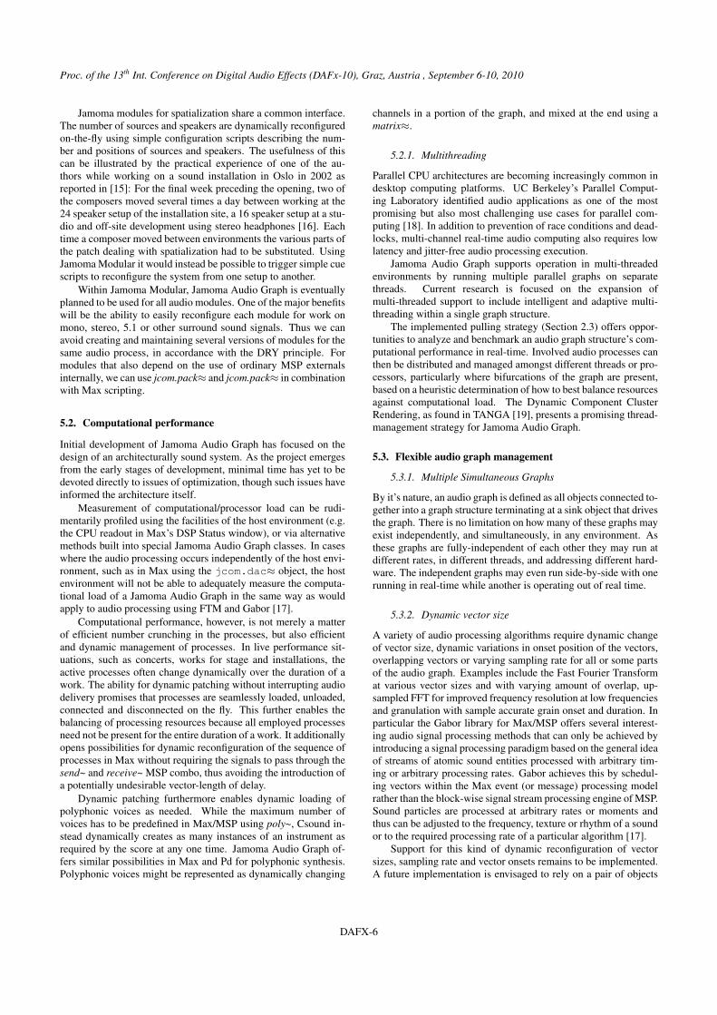
Related to IEM’s CUBEmixer [22], the authors are currentlydeveloping a multi-channel authoring/mixing application whichenables the user to work and combine common spatial audio ren-dering concepts such as VBAP, DBAP, ViMiC [23] and Ambison-ics according to compositional aspiration and/or technical possi-bilities [10]. The Jamoma Audio Graph layer is essential to thisdevelopment and is already being used in a prototype of this appli-cation (Figure 6).
Figure 6: Prototype of an authoring application combining com-mon spatial rendering concepts using Jamoma Audio Graph
6. CONCLUSIONS
The Jamoma Audio Graph framework implements a flexible anddynamic architecture for creating networks of multi-channel unitgenerators that operate in real time. The connections between ob-jects are not only capable of delivering multiple channels of au-dio through each individual connection, but the number of audiochannels may change dynamically during the operation of the au-dio graph. Furthermore, the connections themselves are dynamic,meaning that unit generators may be connected or detached duringthe operation of the audio graph without requiring the signal chainto be re-compiled, and giving rise to live coding and live patch-ing applications. Finally, the vector size of the signal processinggraph, as well as the sample rate of the graph is dynamic withparts of the graph that may operated at different rates for spectral,granular, or other areas of interest.
Through implementations for a variety of text-based andgraphical environments, we have proven the flexibility of the archi-tecture and the potential for great usability improvements to thoseenvironments. We believe the structure to be a good fit for multi-threaded parallel processing, which comprises much of the futuredevelopment of Jamoma Audio Graph. As an open source projectwith cross-platform support, we believe that Jamoma Audio Graphprovides a relevant and applicable model for developing real timeaudio processing systems.
7. ACKNOWLEDGMENTS
The authors wish to thank Alexander Refsum Jensenius and thefourMs lab at the University of Oslo for hosting the workshopduring which the initial architecture of Jamoma Audio Graph wasdesigned. We additionally thank Pascal Baltazar and everyone atGMEA Centre National de Création Musicale for hosting a spa-tialization workshop during which the design of Jamoma AudioGraph was reviewed and heavily revised. Initial development wassupported by The Municipality of Bergen. Øyvind Brandsegg, JeffCarey and IOhannes Zmölnig have provided valuable insight intoprocessing of multi-channel signals in Csound, SuperCollider andPd respectively. Jesse Allison provided assistance with the Rubyon Rails implementation of Jamoma Audio Graph.
8. REFERENCES
[1] Timothy Place, Trond Lossius, and Nils Peters, “A flexibleand dynamic C++ framework and library for digital audiosignal processing,” in Proc. of the International ComputerMusic Conference, New York, US, 2010, pp. 157–164.
DAFX-7
Proc. of the 13th Int. Conference on Digital Audio Effects (DAFx-10), Graz, Austria , September 6-10, 2010
[2] Timothy Place and Trond Lossius, “Jamoma: A modularstandard for structuring patches in Max,” in Proc. of the2006 International Computer Music Conference, New Or-leans, US, 2006, pp. 143 – 146.
[3] Xavier Amatraian, “A domain-specific metamodel for multi-media processing systems,” IEEE Transactions on Multime-dia, vol. 9, no. 6, pp. 1284–1298, 2007.
[4] Ge Wang, The ChucK Audio Programming Lanuage: AStrongly-timed and On-the-fly Envon/mentality, Ph.D. the-sis, Princeton University, 2008.
[5] Steven Yi, “Creating encapsulated instruments in Csound5,”Csound Journal, Winter 2006.
[6] Ross Bencina, “PortAudio and media synchronisation - it’sall in the timing,” in In Proc. of the 2003 Australasian Com-puter Music Association (ACMC’03), 2003, pp. 13–20.
[7] Ville Pulkki, “Virtual sound source positioning using vectorbase amplitude panning,” J. Audio Eng. Soc., vol. 45(6), pp.456–466, 1997.
[8] Trond Lossius, Pascal Baltazar, and Théo de la Hogue,“DBAP - Distance-Based Amplitude Panning,” in Proc. of2009 International Computer Music Conference, Montreal,Canada, 2009, pp. 489–492.
[9] Jan C. Schacher and Philippe Kocher, “Ambisonics Spatial-ization Tools for Max/MSP,” in Proc. of the 2006 Interna-tional Computer Music Conference, New Orleans, US, 2006,pp. 274–277.
[10] Nils Peters, Trond Lossius, Jan Schacher, Pascal Baltazar,Charles Bascou, and Timothy Place, “A stratified approachfor sound spatialization,” in Proc. of 6th Sound and MusicComputing Conference, Porto, Portugal, 2009, pp. 219–224.
[11] Sam Ruby, Dave Thomas, and David Heinemeier Hansson,Agile Web Development with Rails. 3rd edition, The Prag-matic Programmers LLC, 2009.
[12] Nick Collins, Alex McLean, Julian Rohrhuber, and AdrianWard, “Live coding in laptop performance,” OrganisedSound, vol. 8, no. 3, pp. 321–330, December 2003.
[13] Robert C. Martin, Clean code. A handbook of Agile softwarecraftsmanship, Prentice Hall, 2009.
[14] Andrew Hunt and David Thomas, The Pragmatic Program-mer, Addison-Wesley, 1999.
[15] Jøran Rudi, “Norge et lydrike - norway remixed: a soundinstallation,” Organised Sound, vol. 8, no. 2, pp. 151–155,August 2003.
[16] Trond Lossius, Sound Space Body: Reflections on Artis-tic Practice, Ph.D. thesis, Bergen National Academy of theArts, 2007.
[17] Norbert Schnell and Diemo Schwarz, “Gabor, multi-representation real-time analysis/synthesis,” in Proc. ofthe 8th International Conference on Digital Audio Effects(DAFx’05), Madrid, Spain, 2005.
[18] K. Asanovic, R. Bodik, J. Demmel, T. Keaveny, K. Keutzer,J.D. Kubiatowicz, E.A. Lee, N. Morgan, G. Necula, D.A.Patterson, et al., “The parallel computing laboratory at UCBerkeley: A research agenda based on the berkeley view,”Tech. Rep., UC Berkley, Tech. Re. UCB/EECS-2008, 2008.
[19] Andreas Partzsch and Ulrich Reiter, “Multi core / multithread processing in object based real time audio rendering:Approaches and solutions for an optimization problem,” in122th AES Convention, Preprint 7159, 2007.
[20] Stuart Bray and George Tzanetakis, “Implicit patching fordataflow-based audio analysis and synthesis,” in Proc. of the2005 International Computer Music Conference, 2005.
[21] Ville Pulkki, “Spatial sound reproduction with directionalaudio coding,” J. Audio Eng. Soc., vol. 55, no. 6, pp. 503–516, June 2007.
[22] Thomas Musil, Winfried Ritsch, and Johannes M. Zmölnig,“The CUBEmixer a performance-, mixing- and masteringtool,” in Proc. of the 2008 Linux Audio Conference, Colgne,Germany, 2008.
[23] Nils Peters, Tristan Matthews, Jonas Braasch, and StephanMcAdams, “Spatial sound rendering in Max/MSP withViMiC,” in Proc. of the 2008 International Computer Mu-sic Conference, Belfast, UK, 2008, pp. 755–758.
DAFX-8