Embed Size (px)
Citation preview
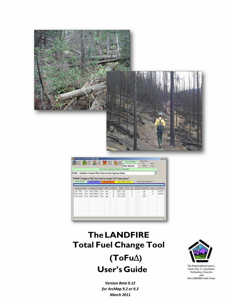
The LANDFIRE
Total Fuel Change Tool
(ToFuΔ)
User’s Guide
Version Beta 0.12
for ArcMap 9.2 or 9.3
March 2011
ToFu∆ User’s Guide Front Matter
2
Preface
LANDFIRE fuel data were originally developed from coarse-scale existing vegetation
type, existing vegetation cover, existing vegetation height, and biophysical setting layers.
Fire and fuel specialists from across the country provided input to the original LANDFIRE
National (LF_1.0.0) fuel layers to help calibrate fuel characteristics on a more localized
scale. The LANDFIRE Total Fuel Change Tool (ToFu∆) was developed from this calibration
process.
Vegetation is subject to constant change – and fuels are therefore also dynamic,
necessitating a systematic method for reflecting changes spatially so that fire behavior
can be accurately accessed. ToFuΔ allows local experts to quickly produce maps that
spatially display any proposed fuel characteristics changes.
ToFu∆ works through a Microsoft Access database to produce spatial results in ArcMap
based on rule sets devised by the user that take into account the existing vegetation
type (EVT), existing vegetation cover (EVC), existing vegetation height (EVH), and
biophysical setting (BpS) from the LANDFIRE grid data. There are also options within
ToFu∆ to add discrete variables in grid format through use of the wildcard option and
for subdividing specific areas for different fuel characteristic assignments through the
BpS grid.
The ToFu∆ user determines the size of the area for assessment by defining a
Management Unit, or “MU.” User-defined rule sets made up of EVT, EVC, EVH, and BpS
layers, as well as any wildcard selections, are used to change or refine fuel
characteristics within the MU. Once these changes have been made to the fuel
characteristics, new grids are created for fire behavior analysis or planning. These grids
represent the most common ToFu∆ output.
ToFuΔ is currently under development and will continue to be updated in the future.
The current beta version (0.12), released in March 2011, is compatible with Windows 7
and will be the last release until the fall of 2011.
ToFu∆ User’s Guide Front Matter
3
Prerequisites
ToFu∆ is compatible with ArcGIS 9.2 and 9.3. When installed, the software will
create a toolbar within ArcMap to access the spatial features of the program. Users
need to be familiar with ArcGIS. More importantly, users must have a good
understanding of fire behavior and effects, as well as knowledge pertaining to fuels
(such as fuel loading models and fire behavior fuel models), weather, topography,
and wildland fire situations. Users should also understand the relationships between
disturbance, vegetation attributes, and fuel characteristics. This knowledge should
be accompanied by the ability to use non-spatial fire behavior and effects prediction
systems such as BehavePlus, NEXUS, and FOFEM.
Specific computer requirements are described in detail in Chapter 1 of this guide.
Obtaining copies
To obtain the latest version of ToFuΔ, additional copies of this ToFuΔ User’s Guide, the ToFuΔ Tutorial, or the ToFuΔ Help Utility, follow these steps:
1. Go to Wildland Fire Management RD&A: Fuels and Fire Ecology (formerly NIFTT ) at https://www.frames.gov/partner-sites/wfmrda-ffe/home/
2. Under Tools, select Archived Tools and User Documents. ToFu Delta is listed here.
3. Select the material you wish to download from those listed in the right-hand column.
Credits
The beta version of ToFuΔ was developed and is maintained for the National Interagency Fuels, Fire, and Vegetation Technology Transfer (NIFTT) by the LANDFIRE
Fuels Team: Tobin Smail1, developer/programmer, and Charley Martin1 and Jim
Napoli1, user interface and function testing.2, 3
1Stinger Ghaffarian Technologies, Inc., contractor to the U.S. Geological Survey (USGS) Earth Resources Observation and
Science (EROS) Center, Sioux Falls, SD. Work performed under contract G10PC00044.
2Any use of trade, firm, or product names is for descriptive purposes only and does not imply endorsement by the U.S.
Government.
3Although this program has been used by the USGS, no warranty, expressed or implied, is made by the USGS or the United States Government as to the accuracy and functioning of the program and related program material nor shall the fact of distribution constitute any such warranty, and no responsibility is assumed by the USGS in connection therewith.

4
ToFu∆ User’s Guide Front Matter
Your input
We value your input. Please forward any questions, comments, reports of bugs, or ideas to https://www.frames.gov/myframes/forum.
5
ToFu∆ User’s Guide Front Matter
Contents The LANDFIRE ............................................................................................1
Preface ................................................................................................................... 2 Prerequisites ........................................................................................................... 3 Obtaining copies ..................................................................................................... 3 Credits .................................................................................................................3 Your input ............................................................................................................... 4
Chapter 1: About the ToFu∆ User’s Guide ...........................................................7 1.1 Before you begin ............................................................................................7 1.2 How to use this guide ....................................................................................... 7 1.3 Computer requirements ................................................................................... 7
Chapter 2: ToFu∆ Function ..................................................................................9 2.1 How ToFu∆ operates .....................................................................................9 2.2 Applications ...................................................................................................... 9
Chapter 3: Inputs ................................................................................................ 11 3.1 Required input data ..................................................................................... 11 3.1.1 Biophysical Settings (BpS) layer ................................................................... 12
3.1.2 Existing Vegetation Type (EVT) layer ............................................................ 13
3.1.3 Existing Vegetation Cover (EVC) layer .......................................................... 13
3.1.4 Existing Vegetation Height (EVH) layer ......................................................... 14
3.2 Optional input data ....................................................................................... 15 3.2.1 Disturbance ...................................................................................................... 15
3.2.2 Wildcard ........................................................................................................... 15
3.2.3 evation .............................................................................................................. 15
3.2.4 slope ................................................................................................................. 16
3.2.5 Aspect .............................................................................................................. 17
3.3 3 Other data................................................................................................. 17 3.3.1 Fire Behavior Fuel Models (FBFM) ................................................................ 18
3.3.2 Canopy Base Height (CBH) ............................................................................ 18
3.3.3 Canopy Bulk Density (CBD) ........................................................................... 19
3.3.4 Canopy Cover (CC)....................................................................................... 20
3.3.5 Canopy Height (CH) ........................................................................................ 21
3.4 Concepts of rule set development for fuel characteristics ............................ 21
3.4.1 Fire Behavior Fuel Model assignments in LANDFIRE National data ......... 21
3.4.2 Canopy guide toggle ....................................................................................... 22
3.4.3 Assigning canopy characteristics ................................................................. 22
Chapter 4: Obtaining Input Data from the LANDFIRE Data Distribution Site...4 4.1 Acquiring input data .......................................................................................4 4.2 Downloading data directly from the LANDFIRE Data Distribution site ........... 4
Chapter 5: Installing ToFu∆ ..................................................................................5 5.1 General installation instructions ....................................................................... 5 5.2 ToFu∆ installation ........................................................................................... 27 5.2.2 Beginning the installation process ................................................................ 27
5.2.3 Obtaining the latest .NET Framework ............................................................ 29
5.2.4 Finishing the installation ................................................................................ 33
5.3 Troubleshooting ToFu∆ installation .............................................................. 35
6
ToFu∆ User’s Guide Front Matter
Chapter 6: A quick start guide to running ToFu∆ .............................................. 37 6.1 Setting up the working directory................................................................... 39 6.2 Creating a Management Unit ....................................................................... 41 6.3 Working with fuel rules ................................................................................... 44 6.4 Evaluating surface and canopy fuel assignments ......................................... 50 6.5 Creating the grid menu ................................................................................ 52 6.6 Selecting canopy options (optional) ............................................................... 54 6.7 Applying changes to specified areas ............................................................ 55 6.8 Creating grids ................................................................................................. 56 6.9 Adjusting rule sets ....................................................................................... 57 6.10 0 Evaluating outputs ................................................................................ 57
Chapter 7: Using ToFu∆ ....................................................................................... 58 7.1 The ToFu∆ toolbar ....................................................................................... 58 7.2 Creating a new project ................................................................................... 60 7.3 Loading data ................................................................................................ 60 7.4 Workspace settings ..................................................................................... 63 7.5 Management Units ......................................................................................... 65 7.6 Fuel rules ..................................................................................................... 71 7.6.1 Fuel rule header selections ............................................................................ 74
7.6.2 Column headers .............................................................................................. 76
7.6.3 Tab indicators .................................................................................................. 80
7.6.4 Rule input options ........................................................................................... 81
7.6.5 Fuel rule page tabs ....................................................................................... 89
7.7 Creating new Grids ...................................................................................... 94 7.8 Fuel grid color palette ..................................................................................... 98 7.9 Deleting fuel Management Units .................................................................... 99 7.10 0 Fuel Log ........................................................................................... 100 7.11 About ToFuΔ ....................................................................................... 101 7.12 Help .................................................................................................... 101
Chapter 8: Troubleshooting ToFu∆ – Common Errors, Symptoms, and Solutions ........................................................................................................... 102
8.1 Common problems ....................................................................................... 102 8.1.1 nstallation errors ........................................................................................... 102
8.1.2 Naming problems .......................................................................................... 102
Appendix A: References ...................................................................................... 103 Appendix B: LANDFIRE Canopy Cover and Height Classification ................. 105
B.1 Canopy Cover Classification ........................................................................ 105 B.2 Canopy Height Classification ....................................................................... 106
Appendix C: Downloading data using the LANDFIRE Data Access Tool (LFDAT).......................................................................................................... 107
7
Chapter 1 ToFu∆ User’s Guide
Chapter 1: About the To Fu∆ User’s Guide
1.1 Before you begin 1.2 2 How to use this guide 1.3 Computer requirements
1.1 Before you begin
This user’s guide describes the basic operation of ToFu∆, which is used to edit surface and canopy fuel characteristics on a specific site or on large landscapes to support fire and fuels analysis.
Prior to using the tool, ToFu∆ users must be familiar with Microsoft Windows and basic ArcGIS functions.
1.2 How to use this guide
It is not necessary to read the entire guide to carry out a specific task. Once you are familiar with the basic concepts associated with ToFu∆, you can quickly locate commonly performed tasks by reviewing the headings in the ‘Table of Contents’ located near the beginning of this guide. You can then refer to the specific section pertaining to your needs. Whenever possible, screen captures are used to illustrate steps required to complete a task.
The ToFu∆ User’s Guide is not intended to provide step-by-step guidance on the tool’s operation; rather, it is intended to serve as a reference guide. The ToFu∆ Tutorial provides basic step-by-step instructions using a specific management scenario as an example.
1.3 Computer requirements
Ensure the following programs are installed and functioning properly on your computer:
ArcGIS 9.2 or 9.3
Spatial Analyst extension of ArcGIS 9.2 or 9.3 Microsoft Excel (2000 or higher, with version 2007 preferred)
Microsoft Access (2000 or higher, with version 2007 preferred)
8
Chapter 1 ToFu∆ User’s Guide
Although system requirements to run ArcGIS 9.2 will suffice to run NIFTT tools, at least 10 GB of free hard drive space and 2 GB of RAM are recommended. Generally, faster processors, more memory, and increased free hard drive space will improve performance. In addition, NIFTT tools were developed for Windows Operating Systems.
Note: Ensure that you have sufficient space and adequate permissions for storing ToFuΔ outputs on your computer.
Tip: Ensure that the ToFu∆ version you are using matches the version of ArcGIS on your computer. This version of ToFu∆ does not work with older versions of ArcGIS (9.0, 9.1, etc.).
Note: Although not required, ArcCatalog is a highly valuable tool for managing and organizing ArcMap data layers and should be used for all data manipulation such as copying, pasting, renaming, and deleting.
9
Chapter 2 ToFu∆ User’s Guide
Chapter 2: ToFu∆ Function
2.1 How ToFu∆ operates 2.2 Applications
2.1 How ToFu∆ operates
ToFu ∆ works through a Microsoft Access database to produce spatial results in ArcMap based on rule sets devised by the user. These rule sets principally take into account the existing vegetation type (EVT), existing vegetation cover (EVC), existing vegetation height (EVH), and biophysical setting (BpS) from the LANDFIRE grid data. There are also options within the fuel change tool to add discrete variables in grid format through use of the wildcard option or by subdividing specific areas for different fuel characteristic assignments through the BpS grid.
ToFuΔ adheres to landscape data file standards for use with FARSITE, FlamMap, WFDSS, FSPRO, FPA, and other fire behavior and fire effects programs.
2.2 Applications
ToFuΔ has numerous and diverse potential management applications. Fire and fuels managers can use ToFuΔ for planning purposes, fire behavior analysts can use the tool on actual incidents, and GIS analysts can use it to update national data sets. It can be used to edit surface and canopy fuel characteristics on a specific site at a local scale or across large landscapes used in fire and fuels analysis at a national scale. Specifically, ToFuΔ can be used to:
Create Canopy Base Height, Canopy Bulk Density, Canadian Fire Behavior Prediction System Fuel Models, 13 - Fire Behavior Fuel Model (Anderson 1982), 40
– Fire Behavior Fuel Model (Scott and Burgan 2005), and GIS GRID layers.
Analyze and validate GIS fire behavior outputs.
Help perform routine and recurring database management operations to allow for progressive manipulation of fuels data during planning efforts, fire incidents, and LANDFIRE fuel calibration.
Display and describe vegetation, ecological processes, and how the data are incorporated into final spatial products.
Capture local expertise from a wide range of specialists on fire behavior and fire effects and distribute these data spatially.
Chapter 3 ToFu∆ User’s Guide
11
Chapter 3: Inputs
3.1 Required input data 3.1.1 Biophysical Settings (BpS) layer 3.1.2 .2 Existing Vegetation Type (EVT) layer 3.1.3 .3 Existing Vegetation Cover (EVC) layer 3.1.4 .4 Existing Vegetation Height (EVH) layer
3.2 Optional input data 3.2.1 Disturbance 3.2.2 Wildcard 3.2.3 Slope 3.2.4 Aspect 3.2.5 Elevation
3.3 Other data 3.3.1 Fire Behavior Fuel Models (FBFM) 3.3.2 Canopy Base Height (CBH) 3.3.3 Canopy Bulk Density (CBD) 3.3.4 Canopy Cover (CC) 3.3.5 Canopy Height (CH)
3.4 Concepts of rule set development for fuel characteristics 3.4.1 Fire Behavior Fuel Model assignments in LANDFIRE National data 3.4.2 Canopy guide toggle 3.4.3 Assigning canopy characteristics
3.1 Required input data
The Management Unit (MU) serves as the basic building block for changing fuel characteristics in a particular area. The extent of the MU is defined by the user and can be designated by using coordinates or the intersection of the input grid layers. Four separate LANDFIRE data sets are required to build an MU and run ToFuΔ: Existing Vegetation Type (EVT), Existing Vegetation Cover (EVC), Existing Vegetation Height (EVH), and Biophysical Settings (BpS).
For development and processing within the LANDFIRE Project, map zones were used as the standard area for analysis. The default data set was processed by LANDFIRE map zones and consequently, rule sets for fuels characteristics that are within the default are set at that extent. The grid layers of EVT EVC, EVH, and BpS (all set to the extent of each LANDFIRE map zone) were combined for processing.
Chapter 3 ToFu∆ User’s Guide
12
The four required grids EVT, EVC, EVH, and BpS must be downloaded from the LANDFIRE Data Distribution Site at http://landfire.gov/viewer/. (See Chapter 4 for additional information on how to access and download required data.)
Note: Because ToFuΔ was developed to process LANDFIRE data, the classifications of EVT, EVC, EVH, and BpS are imbedded in the tool’s nomenclature; therefore other data sets with different classification systems cannot be used.
These layers are described briefly below. For additional information on these required input items, consult www.landfire.gov.
3.1.1 Biophysical Settings (BpS) layer
Biophysical settings reflect the integration of soils, climate, and topography which define native disturbance regimes and the composition of resulting plant communities. Biophysical settings are the taxonomic units used to characterize reference conditions. The natural composition of succession classes has been determined for each BpS by using either spatial vegetation succession and disturbance models, such as LANDSUM (Keane and others 2006) and TELSA (ESSA Technologies Ltd. 2005a) or aspatial vegetation succession and disturbance models, such as the Vegetation Dynamics Development Tool (VDDT; ESSA Technologies Ltd. 2005b).
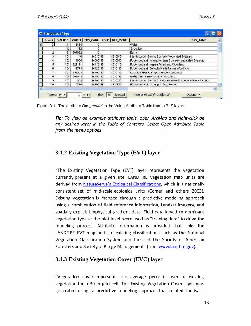
Depending on the analysis area, there may be as many as one hundred or more BpS types. Biophysical settings lacking a set of reference conditions (such as barren, water, agriculture, and urban) are ignored when calculating landscape composition and deriving departure indices. For example, if agriculture comprises 10 percent of a landscape, the composition of succession classes is determined from the remaining 90 percent of that landscape. An example value attribute table for a BpS layer is shown below (fig. 3-1).
Chapter 3 ToFu∆ User’s Guide
13
Figure 3-1. The attribute Bps_model in the Value Attribute Table from a BpS layer.
Tip: To view an example attribute table, open ArcMap and right-click on any desired layer in the Table of Contents. Select Open Attribute Table from the menu options
3.1.2 Existing Vegetation Type (EVT) layer
“The Existing Vegetation Type (EVT) layer represents the vegetation
currently present at a given site. LANDFIRE vegetation map units are
derived from N atureSer ve’s Ecological Classif icat ion s , which is a nationally
consistent set of mid-scale ecological units (Comer and others 2003).
Existing vegetation is mapped through a predictive modeling approach
using a combination of field reference information, Landsat imagery, and
spatially explicit biophysical gradient data. Field data keyed to dominant
vegetation type at the plot level were used as "training data" to drive the
modeling process. Attribute information is provided that links the
LANDFIRE EVT map units to existing classifications such as the National
Vegetation Classification System and those of the Society of American
Foresters and Society of Range Management” (from www.landfire.gov).
3.1.3 Existing Vegetation Cover (EVC) layer
“Vegetation cover represents the average percent cover of existing
vegetation for a 30-m grid cell. The Existing Vegetation Cover layer was
generated using a predictive modeling approach that related Landsat
Chapter 3 ToFu∆ User’s Guide
14
imagery and spatially explicit biophysical gradients to calculated values of
average canopy cover from field training sites and digital orthophoto
quadrangles” (from www.landfire.gov).
Tofu∆ “reads” the life form of the pixels within each grid and displays the
life form that the rule set will be describing. The LANDFIRE numbering
scheme for EVC denotes which vegetation strata are being identified as well
as the range of cover in 10% increments of that life form. The LANDFIRE
data used by the tool are coded within the grid according to the numeric
values described below. (These values will be used to edit fuel rules.)
Tree – Tree cover is numerically structured 101 to 109 in cover
classes of 10%: 101 = 10-19% with a midpoint of 15%, 102= 20-29%, and so on to 109 = 90-99% tree cover.
Shrub – Shrub cover is expressed in an “11 series” so that a coding of 111= 10-19% and so on to 119 = 90-99% shrub cover.
Herbaceous – Herbaceous cover is expressed in a “12 series” of 10% class increments so that a 121 class = 10-19%, 122 = 20-29%, and so on to 129 = 90-99% herbaceous cover.
Note: After editing cover in the fuel rules and creating a grid, the midpoint of the range (the 10% increment) of cover will be used to describe canopy cover if the grid is then input into a Landscape file for spatial fire behavior analysis.
3.1.4 Existing Vegetation Height (EVH) layer
“Vegetation height represents the average height of the dominant vegetation
for a 30-m grid cell. The LANDFIRE Canopy Height layer was generated using a
predictive modeling approach that related Landsat imagery and spatially
explicit biophysical gradients to calculated values of average dominant height
from field training sites” (from www.landfire.gov).
The LANDFIRE numbering scheme for EVH denotes which vegetation strata
are being identified and the range of height in 10% increments of that life
form. Life forms are coded as follows.
Chapter 3 ToFu∆ User’s Guide
15
Tree – Pixels are coded in classes as follows: 108 (0-5.0m), 109 (5.0- 10.0m), 110 (10.0-25.0m), 111 (25.0-50.0m), and 112 (>50m).
Shrub – Pixels are coded in classes as follows: 104 (0-0.5m), 105 (0.5- 1.0m), 106 (1.0-3.0m), and 107 (>3.0m).
Herbaceous – Pixels are coded in classes as follows: 101 (0-0.5 meters), 102 (0.5- 1.0m), and 103 (> 1m).
See Appendix B: LANDFIRE Canopy Cover and Height Classification for additional information.
3.2 Optional input data
3.2.1 Disturbance
The Disturbance layer is used in the LANDFIRE Refresh process (see
www.landfire.gov) to update circa 2001 data to 2008 given the effects of
disturbance on the landscape. Raster data sets are made up of disturbance
polygons that included fuel rules for disturbance type, intensity, and time
since disturbance. This functionality will be available for user input in the
final version of ToFu∆.
3.2.2 Wildcard
Wildcard inputs to ToFu∆ can include prepared fuel raster data such as fuel
model or canopy attributes. Often, grids built and processed through the tool
are brought into a combine with EVT, EVC, EVH, and BpS after changes have
been made to those layers in order to set the fuel data. Any other grid data
that may have an effect on the fuel type within an EVT may also be used. For
example, elevation may be used to differentiate lowland fuel models as
opposed to upland areas in the same EVT. Aspect and slope can be included
as wildcard data.
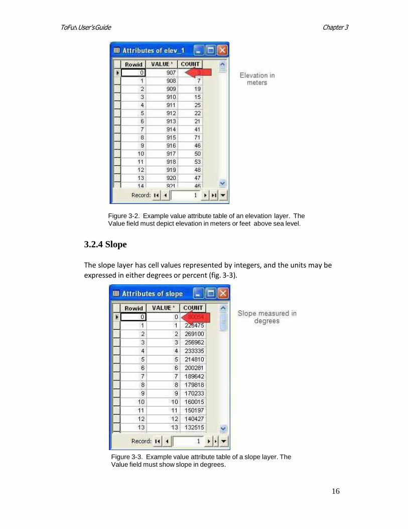
3.2.3 Elevation
The elevation layer represents meters or feet above sea level, and zero values
are used for those areas that are at or below sea level (fig. 3-2).
Chapter 3 ToFu∆ User’s Guide
16
Figure 3-2. Example value attribute table of an elevation layer. The Value field must depict elevation in meters or feet above sea level.
3.2.4 Slope
The slope layer has cell values represented by integers, and the units may be
expressed in either degrees or percent (fig. 3-3).
Figure 3-3. Example value attribute table of a slope layer. The Value field must show slope in degrees.
Chapter 3 ToFu∆ User’s Guide
17
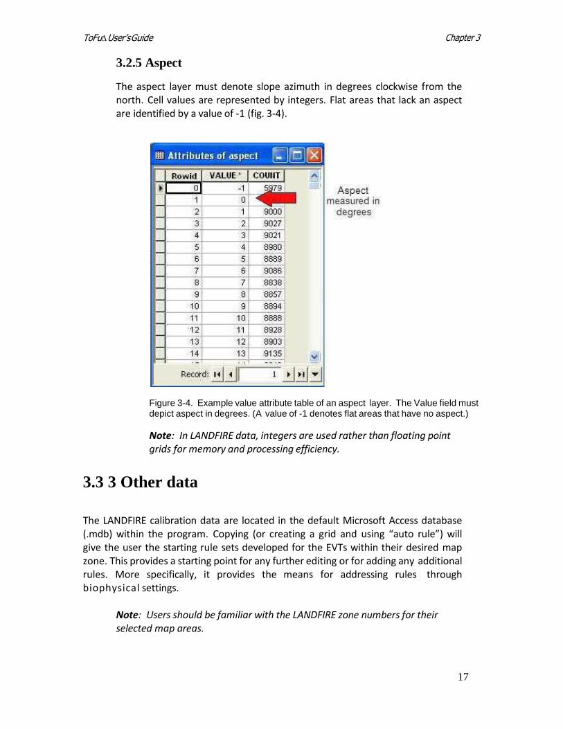
3.2.5 Aspect
The aspect layer must denote slope azimuth in degrees clockwise from the north. Cell values are represented by integers. Flat areas that lack an aspect are identified by a value of -1 (fig. 3-4).
Figure 3-4. Example value attribute table of an aspect layer. The Value field must depict aspect in degrees. (A value of -1 denotes flat areas that have no aspect.)
Note: In LANDFIRE data, integers are used rather than floating point grids for memory and processing efficiency.
3.3 3 Other data
The LANDFIRE calibration data are located in the default Microsoft Access database (.mdb) within the program. Copying (or creating a grid and using “auto rule”) will give the user the starting rule sets developed for the EVTs within their desired map zone. This provides a starting point for any further editing or for adding any additional rules. More specifically, it provides the means for addressing rules through biophysical settings.
Note: Users should be familiar with the LANDFIRE zone numbers for their selected map areas.
18
Chapter 3 ToFu∆ User’s Guide
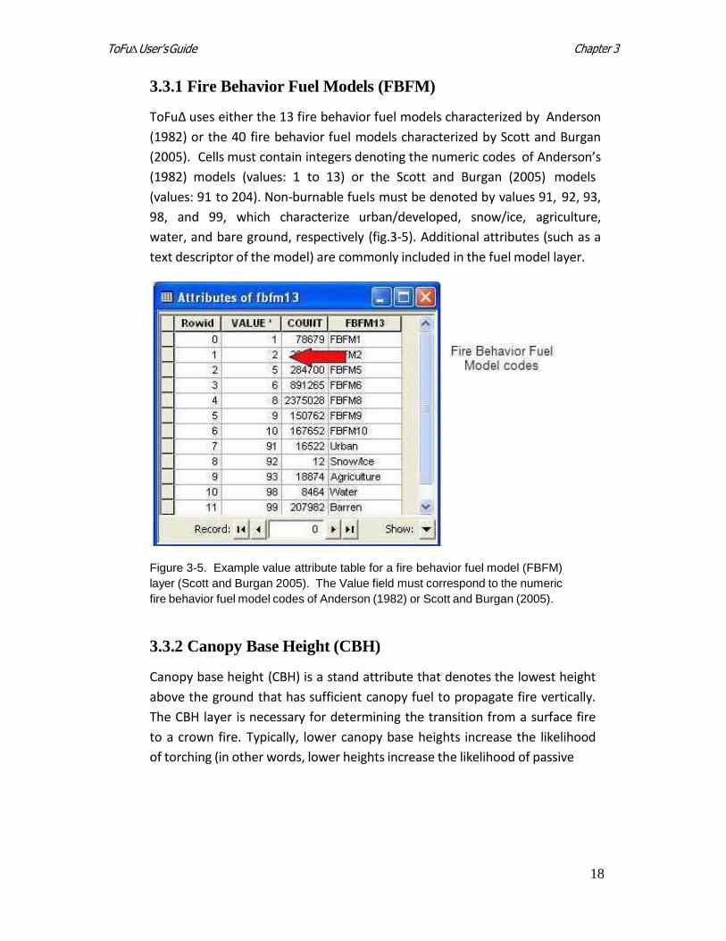
3.3.1 Fire Behavior Fuel Models (FBFM)
ToFuΔ uses either the 13 fire behavior fuel models characterized by Anderson
(1982) or the 40 fire behavior fuel models characterized by Scott and Burgan
(2005). Cells must contain integers denoting the numeric codes of Anderson’s
(1982) models (values: 1 to 13) or the Scott and Burgan (2005) models
(values: 91 to 204). Non-burnable fuels must be denoted by values 91, 92, 93,
98, and 99, which characterize urban/developed, snow/ice, agriculture,
water, and bare ground, respectively (fig.3-5). Additional attributes (such as a
text descriptor of the model) are commonly included in the fuel model layer.
Figure 3-5. Example value attribute table for a fire behavior fuel model (FBFM)
layer (Scott and Burgan 2005). The Value field must correspond to the numeric
fire behavior fuel model codes of Anderson (1982) or Scott and Burgan (2005).
3.3.2 Canopy Base Height (CBH)
Canopy base height (CBH) is a stand attribute that denotes the lowest height
above the ground that has sufficient canopy fuel to propagate fire vertically.
The CBH layer is necessary for determining the transition from a surface fire
to a crown fire. Typically, lower canopy base heights increase the likelihood
of torching (in other words, lower heights increase the likelihood of passive
19
Chapter 3 ToFu∆ User’s Guide
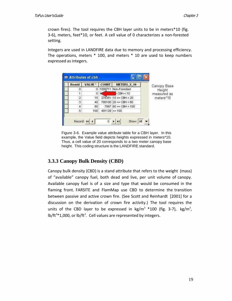
crown fires). The tool requires the CBH layer units to be in meters*10 (fig. 3-6), meters, feet*10, or feet. A cell value of 0 characterizes a non-forested setting.
Integers are used in LANDFIRE data due to memory and processing efficiency. The operations, meters * 100, and meters * 10 are used to keep numbers expressed as integers.
Figure 3-6. Example value attribute table for a CBH layer. In this example, the Value field depicts heights expressed in meters*10. Thus, a cell value of 20 corresponds to a two meter canopy base height. This coding structure is the LANDFIRE standard.
3.3.3 Canopy Bulk Density (CBD)
Canopy bulk density (CBD) is a stand attribute that refers to the weight (mass)
of “available” canopy fuel, both dead and live, per unit volume of canopy.
Available canopy fuel is of a size and type that would be consumed in the
flaming front. FARSITE and FlamMap use CBD to determine the transition
between passive and active crown fire. (See Scott and Reinhardt [2001] for a
discussion on the derivation of crown fire activity.) The tool requires the
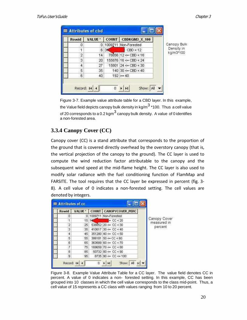
units of the CBD layer to be expressed in kg/m3 *100 (fig. 3-7), kg/m3,
lb/ft3*1,000, or lb/ft3. Cell values are represented by integers.
20
Chapter 3 ToFu∆ User’s Guide
Figure 3-7. Example value attribute table for a CBD layer. In this example,
the Value field depicts canopy bulk density in kg/m3
*100. Thus a cell value
of 20 corresponds to a 0.2 kgm3
canopy bulk density. A value of 0 identifies a non-forested area.
3.3.4 Canopy Cover (CC)
Canopy cover (CC) is a stand attribute that corresponds to the proportion of
the ground that is covered directly overhead by the overstory canopy (that is,
the vertical projection of the canopy to the ground). The CC layer is used to
compute the wind reduction factor attributable to the canopy and the
subsequent wind speed at the mid-flame height. The CC layer is also used to
modify solar radiance with the fuel conditioning function of FlamMap and
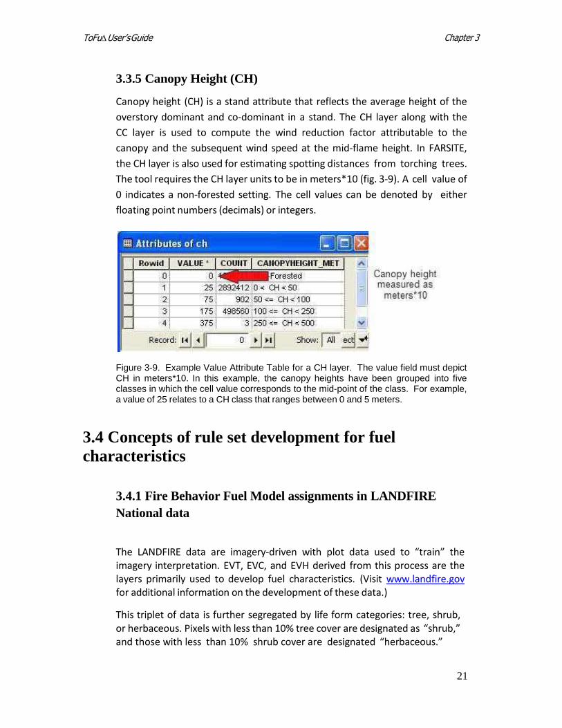
FARSITE. The tool requires that the CC layer be expressed in percent (fig. 3-
8). A cell value of 0 indicates a non-forested setting. The cell values are
denoted by integers.
Figure 3-8. Example Value Attribute Table for a CC layer. The value field denotes CC in percent. A value of 0 indicates a non- forested setting. In this example, CC has been grouped into 10 classes in which the cell value corresponds to the class mid-point. Thus, a cell value of 15 represents a CC class with values ranging from 10 to 20 percent.
21
Chapter 3 ToFu∆ User’s Guide
3.3.5 Canopy Height (CH)
Canopy height (CH) is a stand attribute that reflects the average height of the
overstory dominant and co-dominant in a stand. The CH layer along with the
CC layer is used to compute the wind reduction factor attributable to the
canopy and the subsequent wind speed at the mid-flame height. In FARSITE,
the CH layer is also used for estimating spotting distances from torching trees.
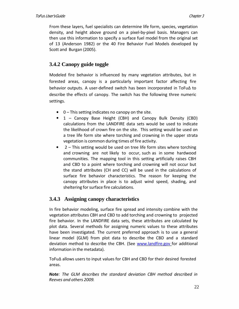
The tool requires the CH layer units to be in meters*10 (fig. 3-9). A cell value of
0 indicates a non-forested setting. The cell values can be denoted by either
floating point numbers (decimals) or integers.
Figure 3-9. Example Value Attribute Table for a CH layer. The value field must depict CH in meters*10. In this example, the canopy heights have been grouped into five classes in which the cell value corresponds to the mid-point of the class. For example, a value of 25 relates to a CH class that ranges between 0 and 5 meters.
3.4 Concepts of rule set development for fuel
characteristics
3.4.1 Fire Behavior Fuel Model assignments in LANDFIRE
National data
The LANDFIRE data are imagery-driven with plot data used to “train” the imagery interpretation. EVT, EVC, and EVH derived from this process are the layers primarily used to develop fuel characteristics. (Visit www.landfire.gov for additional information on the development of these data.)
This triplet of data is further segregated by life form categories: tree, shrub, or herbaceous. Pixels with less than 10% tree cover are designated as “shrub,” and those with less than 10% shrub cover are designated “herbaceous.”
22
Chapter 3 ToFu∆ User’s Guide
From these layers, fuel specialists can determine life form, species, vegetation density, and height above ground on a pixel-by-pixel basis. Managers can then use this information to specify a surface fuel model from the original set of 13 (Anderson 1982) or the 40 Fire Behavior Fuel Models developed by Scott and Burgan (2005).
3.4.2 Canopy guide toggle
Modeled fire behavior is influenced by many vegetation attributes, but in
forested areas, canopy is a particularly important factor affecting fire
behavior outputs. A user-defined switch has been incorporated in ToFu∆ to
describe the effects of canopy. The switch has the following three numeric
settings.
0 – This setting indicates no canopy on the site.
1 – Canopy Base Height (CBH) and Canopy Bulk Density (CBD) calculations from the LANDFIRE data sets would be used to indicate the likelihood of crown fire on the site. This setting would be used on a tree life form site where torching and crowning in the upper strata vegetation is common during times of fire activity.
2 – This setting would be used on tree life form sites where torching and crowning are not likely to occur, such as in some hardwood communities. The mapping tool in this setting artificially raises CBH and CBD to a point where torching and crowning will not occur but the stand attributes (CH and CC) will be used in the calculations of surface fire behavior characteristics. The reason for keeping the canopy attributes in place is to adjust wind speed, shading, and sheltering for surface fire calculations.
3.4.3 Assigning canopy characteristics
In fire behavior modeling, surface fire spread and intensity combine with the vegetation attributes CBH and CBD to add torching and crowning to projected fire behavior. In the LANDFIRE data sets, these attributes are calculated by plot data. Several methods for assigning numeric values to these attributes have been investigated. The current preferred approach is to use a general linear model (GLM) from plot data to describe the CBD and a standard deviation method to describe the CBH. (See www.landfire.gov for additional information in the metadata).
ToFuΔ allows users to input values for CBH and CBD for their desired forested areas.
Note: The GLM describes the standard deviation CBH method described in Reeves and others 2009.
Chapter 4 ToFu Δ User’s Guide
25
Chapter 4: Obtaining Input Data from the
LANDFIRE Data Distribution Site
4.1 Acquiring input data 4.2 Downloading data directly from the LANDFIRE Data Distribution site
4.1 Acquiring input data
The LANDFIRE Program has developed nationally consistent data – across ownerships – of the spatial themes necessary for running ToFu∆ as well as those used in FARSITE and FlamMap. The LANDFIRE website provides links that allow the user to download any of the separate spatial data themes (elevation, slope, aspect, canopy cover, fire behavior fuel model, canopy bulk density, canopy base height, and canopy height). The four grids required to run ToFu∆ are: Existing Vegetation Type (EVT), Existing Vegetation Cover (EVC), Existing Vegetation Height (EVH), and Biophysical Settings (BpS). All of these grids can be downloaded from www.landfire.gov.
4.2 Downloading data directly from the LANDFIRE
Data Distribution site
On www.landfire.gov, click on the Data Distribution Site link and download the desired input layers. Explore the site for additional information on resources offered.
Once you are familiar with the Data Distribution Site, acquiring LANDFIRE data using the LANDFIRE Data Access Tool (LFDAT) is the most efficient method for both downloading and processing LANDFIRE data directly within ArcMap. See Appendix C for details on how to use LFDAT to download data.
Chapter 5 ToFu Δ User’s Guide
Chapter 5: Installing To Fu∆
5.1 General installation instructions 5.2 ToFu∆ installation
5.2.1 Downloading ToFu∆ 5.2.2 Beginning the installation process 5.2.3 Obtaining the latest .NET framework 5.2.4 Finishing the installation
5.3 Troubleshooting ToFu∆ installation
5.1 General installation instructions
All NIFTT tools, including ToFu∆ are now downloaded and installed as single tools. A complete or package install is no longer available for versions of NIFTT tools compatible with ArcMap 9.2 or 9.3.
Note: For ToFu∆ version 1.0 to operate properly, verify that you are using ArcGIS 9.2 or 9.3.
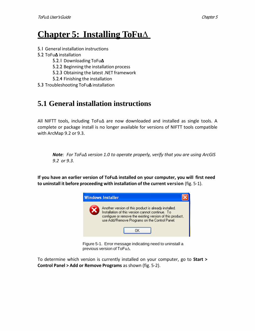
If you have an earlier version of ToFu∆ installed on your computer, you will first need to uninstall it before proceeding with installation of the current version (fig. 5-1).
Figure 5-1. Error message indicating need to uninstall a previous version of ToFu∆.
To determine which version is currently installed on your computer, go to Start > Control Panel > Add or Remove Programs as shown (fig. 5-2).
Chapter 5 ToFu∆ User’s Guide
27
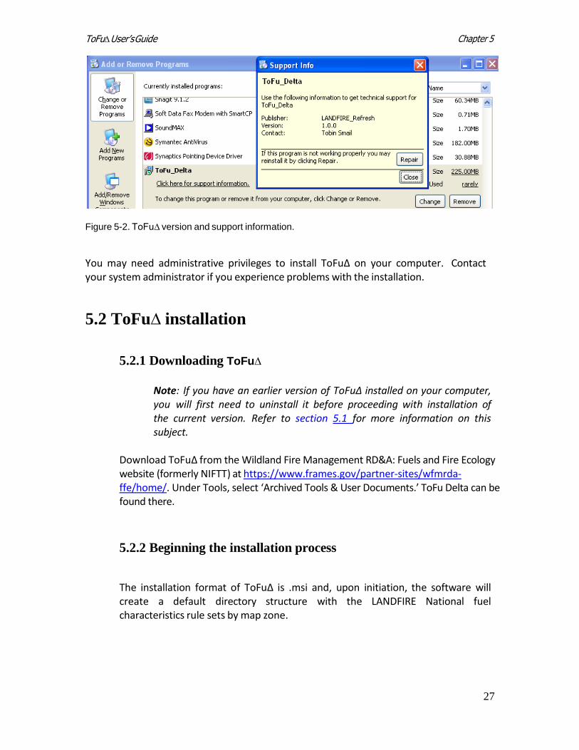
Figure 5-2. ToFu∆ version and support information.
You may need administrative privileges to install ToFuΔ on your computer. Contact your system administrator if you experience problems with the installation.
5.2 ToFu∆ installation
5.2.1 Downloading ToFu∆
Note: If you have an earlier version of ToFu∆ installed on your computer, you will first need to uninstall it before proceeding with installation of the current version. Refer to section 5.1 for more information on this subject.
Download ToFu∆ from the Wildland Fire Management RD&A: Fuels and Fire Ecology website (formerly NIFTT) at https://www.frames.gov/partner-sites/wfmrda-ffe/home/. Under Tools, select ‘Archived Tools & User Documents.’ ToFu Delta can be found there.
5.2.2 Beginning the installation process
The installation format of ToFu∆ is .msi and, upon initiation, the software will create a default directory structure with the LANDFIRE National fuel characteristics rule sets by map zone.
Chapter 5 ToFu∆ User’s Guide
28
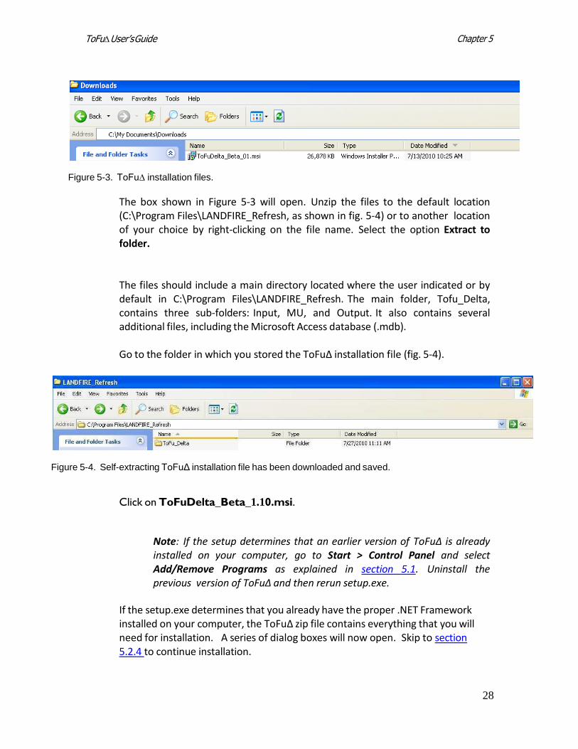
Figure 5-3. ToFu∆ installation files.
The box shown in Figure 5-3 will open. Unzip the files to the default location (C:\Program Files\LANDFIRE_Refresh, as shown in fig. 5-4) or to another location of your choice by right-clicking on the file name. Select the option Extract to folder.
The files should include a main directory located where the user indicated or by default in C:\Program Files\LANDFIRE_Refresh. The main folder, Tofu_Delta, contains three sub-folders: Input, MU, and Output. It also contains several additional files, including the Microsoft Access database (.mdb).
Go to the folder in which you stored the ToFu∆ installation file (fig. 5-4).
Figure 5-4. Self-extracting ToFuΔ installation file has been downloaded and saved.
Click on ToFuDelta_Beta_1.10.msi.
Note: If the setup determines that an earlier version of ToFu∆ is already installed on your computer, go to Start > Control Panel and select Add/Remove Programs as explained in section 5.1. Uninstall the previous version of ToFuΔ and then rerun setup.exe.
If the setup.exe determines that you already have the proper .NET Framework installed on your computer, the ToFu∆ zip file contains everything that you will need for installation. A series of dialog boxes will now open. Skip to section 5.2.4 to continue installation.
Chapter 5 ToFu∆ User’s Guide
29
5.2.3 Obtaining the latest .NET Framework
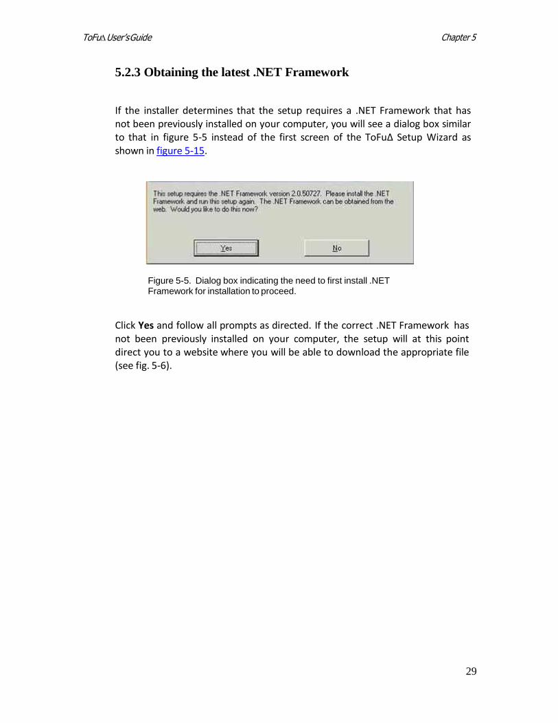
If the installer determines that the setup requires a .NET Framework that has not been previously installed on your computer, you will see a dialog box similar to that in figure 5-5 instead of the first screen of the ToFu∆ Setup Wizard as shown in figure 5-15.
Figure 5-5. Dialog box indicating the need to first install .NET Framework for installation to proceed.
Click Yes and follow all prompts as directed. If the correct .NET Framework has not been previously installed on your computer, the setup will at this point direct you to a website where you will be able to download the appropriate file (see fig. 5-6).
Chapter 5 ToFu∆ User’s Guide
30
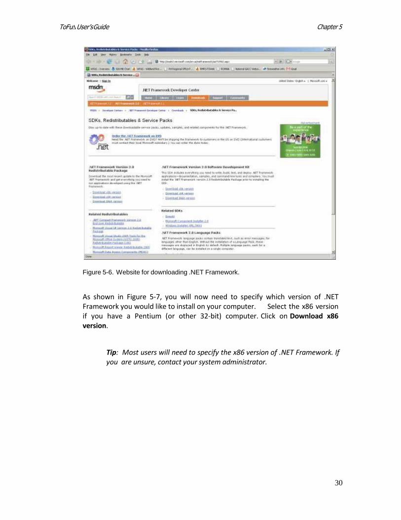
Figure 5-6. Website for downloading .NET Framework.
As shown in Figure 5-7, you will now need to specify which version of .NET Framework you would like to install on your computer. Select the x86 version if you have a Pentium (or other 32-bit) computer. Click on Download x86 version.
Tip: Most users will need to specify the x86 version of .NET Framework. If you are unsure, contact your system administrator.
Chapter 5 ToFu∆ User’s Guide
31
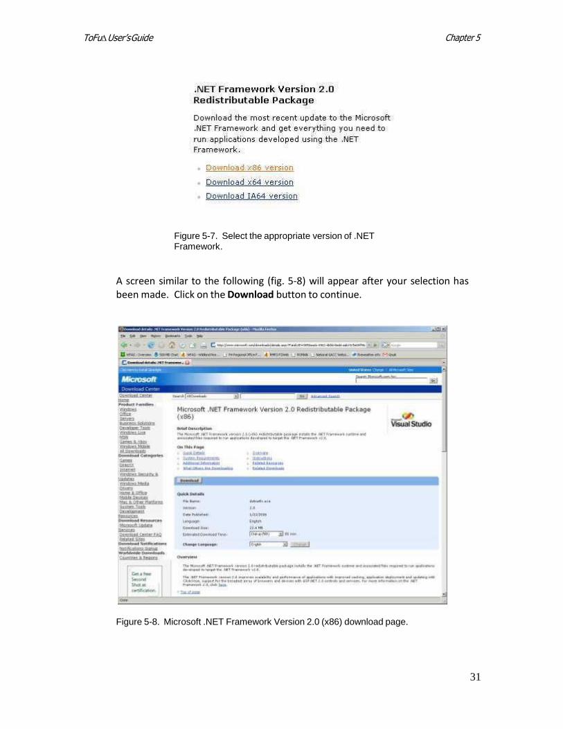
Figure 5-7. Select the appropriate version of .NET Framework.
A screen similar to the following (fig. 5-8) will appear after your selection has been made. Click on the Download button to continue.
Figure 5-8. Microsoft .NET Framework Version 2.0 (x86) download page.
Chapter 5 ToFu∆ User’s Guide
32
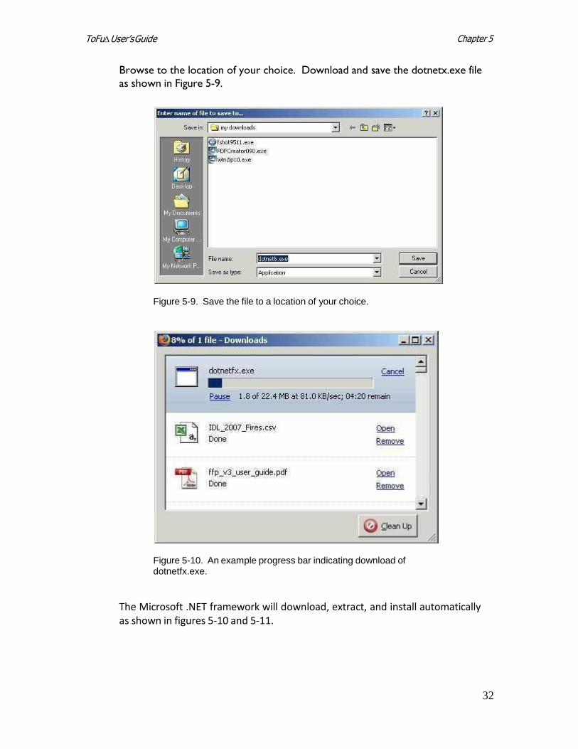
Browse to the location of your choice. Download and save the dotnetx.exe file
as shown in Figure 5-9.
Figure 5-9. Save the file to a location of your choice.
Figure 5-10. An example progress bar indicating download of dotnetfx.exe.
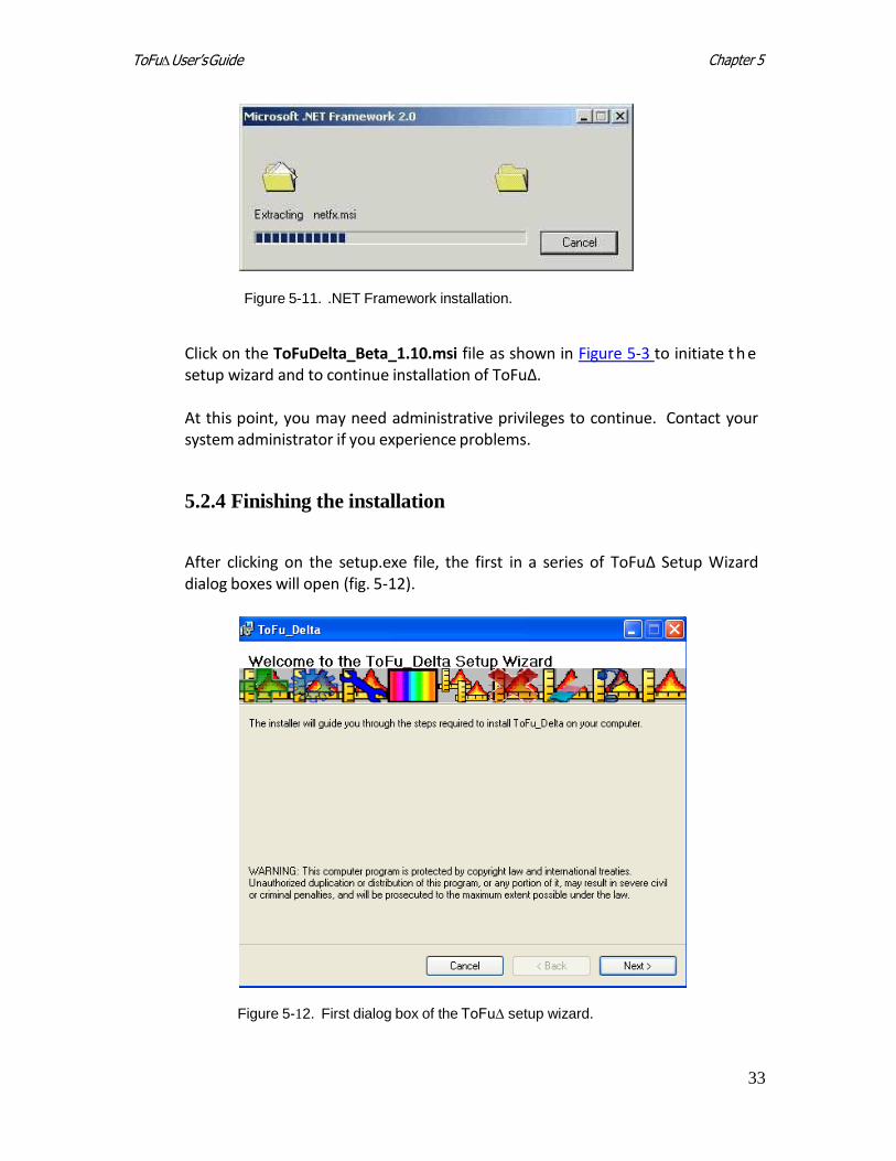
The Microsoft .NET framework will download, extract, and install automatically as shown in figures 5-10 and 5-11.
Chapter 5 ToFu∆ User’s Guide
33
Figure 5-11. .NET Framework installation.
Click on the ToFuDelta_Beta_1.10.msi file as shown in Figure 5-3 to initiate t h e setup wizard and to continue installation of ToFu∆.
At this point, you may need administrative privileges to continue. Contact your system administrator if you experience problems.
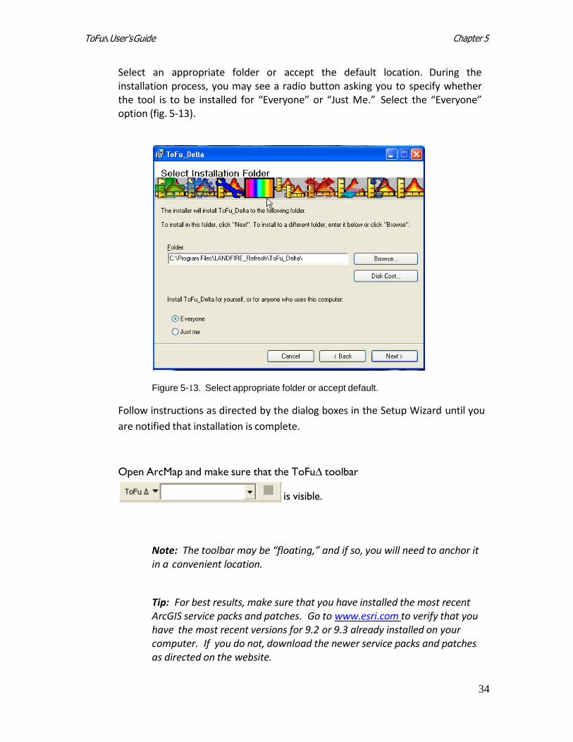
5.2.4 Finishing the installation
After clicking on the setup.exe file, the first in a series of ToFu∆ Setup Wizard dialog boxes will open (fig. 5-12).
Figure 5-12. First dialog box of the ToFu∆ setup wizard.
Chapter 5 ToFu∆ User’s Guide
34
Select an appropriate folder or accept the default location. During the installation process, you may see a radio button asking you to specify whether the tool is to be installed for “Everyone” or “Just Me.” Select the “Everyone” option (fig. 5-13).
Figure 5-13. Select appropriate folder or accept default.
Follow instructions as directed by the dialog boxes in the Setup Wizard until you
are notified that installation is complete.
Open ArcMap and make sure that the ToFu∆ toolbar
is visible.
Note: The toolbar may be “floating,” and if so, you will need to anchor it in a convenient location.
Tip: For best results, make sure that you have installed the most recent ArcGIS service packs and patches. Go to www.esri.com to verify that you have the most recent versions for 9.2 or 9.3 already installed on your computer. If you do not, download the newer service packs and patches as directed on the website.
Chapter 5 ToFu∆ User’s Guide
35
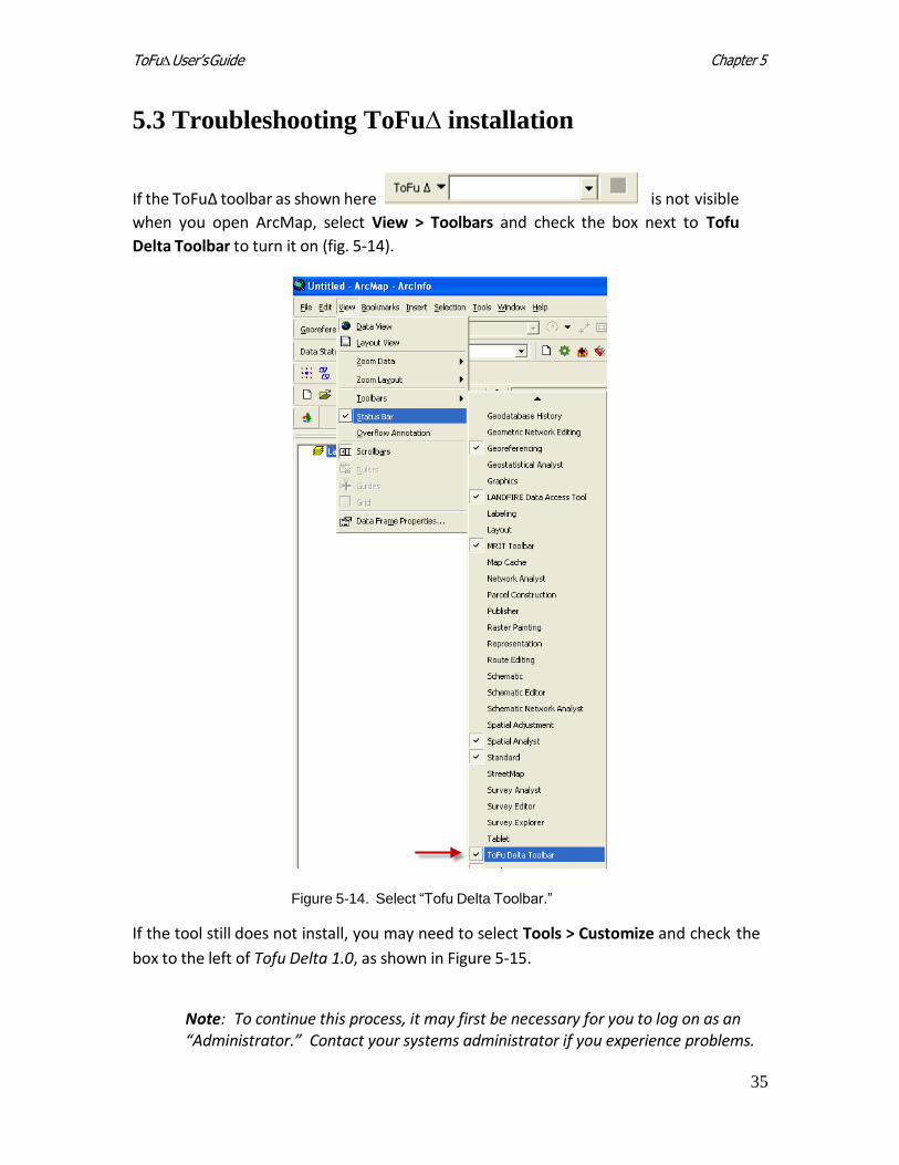
5.3 Troubleshooting ToFu∆ installation
If the ToFu∆ toolbar as shown here is not visible
when you open ArcMap, select View > Toolbars and check the box next to Tofu
Delta Toolbar to turn it on (fig. 5-14).
Figure 5-14. Select “Tofu Delta Toolbar.”
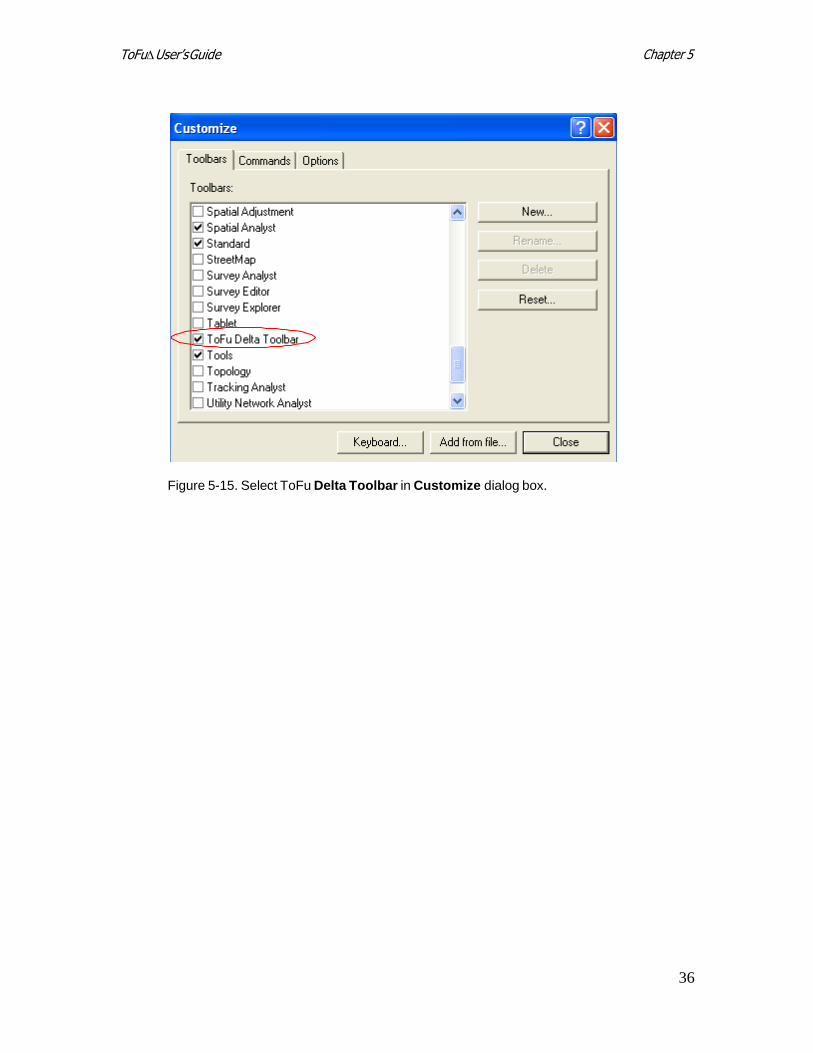
If the tool still does not install, you may need to select Tools > Customize and check the
box to the left of Tofu Delta 1.0, as shown in Figure 5-15.
Note: To continue this process, it may first be necessary for you to log on as an “Administrator.” Contact your systems administrator if you experience problems.
Chapter 5 ToFu∆ User’s Guide
36
Figure 5-15. Select ToFu Delta Toolbar in Customize dialog box.
37
Chapter 6 TofuΔ User’sGuide
Chapter 6: A quick start guide to running
To Fu∆
6.1 Setting up the working directory 6.2 Creating a Management Unit (MU) 6.3 Working with fuel rules 6.4 Evaluating surface and canopy fuel assignments 6.5 Creating the grid menu 6.6 Selecting canopy options 6.7 Applying changes to specified areas 6.8 Creating grids 6.9 Adjusting rule sets 6.10 Evaluating outputs
This purpose of this chapter is to provide a brief overview of many of the basic steps
required to run ToFuΔ. To learn more about all available tool options, proceed to
Chapter 7: Using Tof u ∆. Advanced users seeking detailed information on all available
options, or users looking for help on a specific topic may find the next chapter to be
more useful. This chapter does not discuss every option for each step of the process.
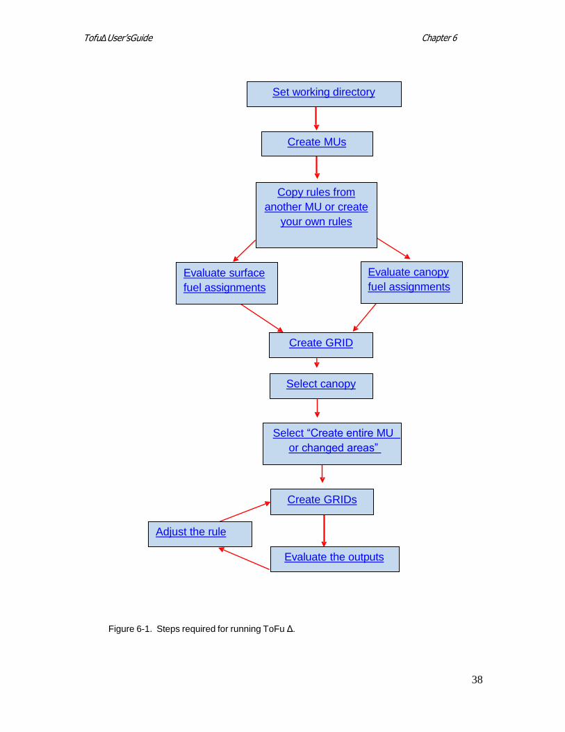
The following flowchart shows the basic steps required to run ToFuΔ (fig. 6-1). Click on
the flowchart’s links for information describing each stage of the process.
38
Chapter 6 TofuΔ User’sGuide
Evaluate canopy
fuel assignments
Figure 6-1. Steps required for running ToFu Δ.
Set working directory
Create MUs
Copy rules from
another MU or create
your own rules
Evaluate surface
fuel assignments
Create GRID
Select canopy
Select “Create entire MU
or changed areas”
Adjust the rule
Evaluate the outputs
Create GRIDs
39
Chapter 6 TofuΔ User’sGuide
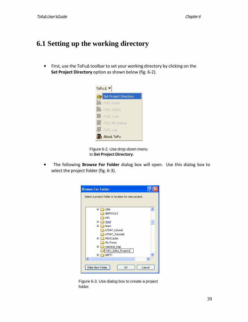
6.1 Setting up the working directory
First, use the ToFuΔ toolbar to set your working directory by clicking on the Set Project Directory option as shown below (fig. 6-2).
Figure 6-2. Use drop-down menu
to Set Project Directory.
The following Browse For Folder dialog box will open. Use this dialog box to select the project folder (fig. 6-3).
Figure 6-3. Use dialog box to create a project
folder.
40
Chapter 6 TofuΔ User’sGuide
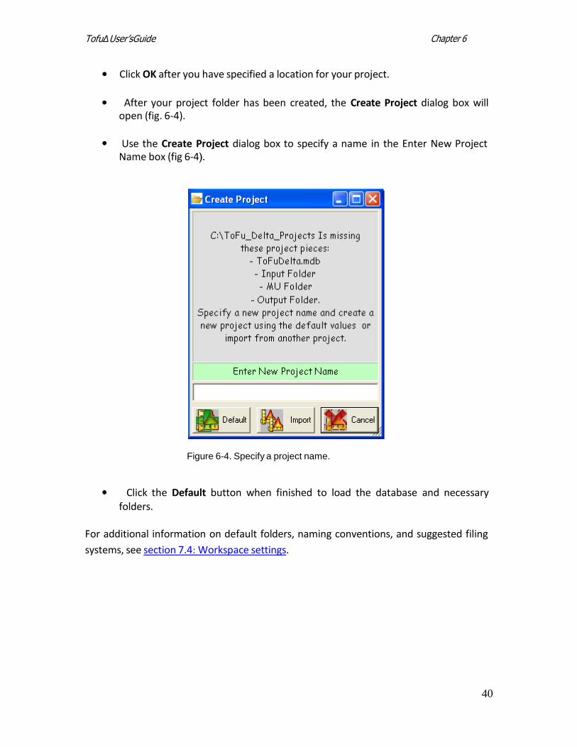
Click OK after you have specified a location for your project.
After your project folder has been created, the Create Project dialog box will
open (fig. 6-4).
Use the Create Project dialog box to specify a name in the Enter New Project
Name box (fig 6-4).
Figure 6-4. Specify a project name.
Click the Default button when finished to load the database and necessary folders.
For additional information on default folders, naming conventions, and suggested filing
systems, see section 7.4: Workspace settings.
41
Chapter 6 TofuΔ User’sGuide
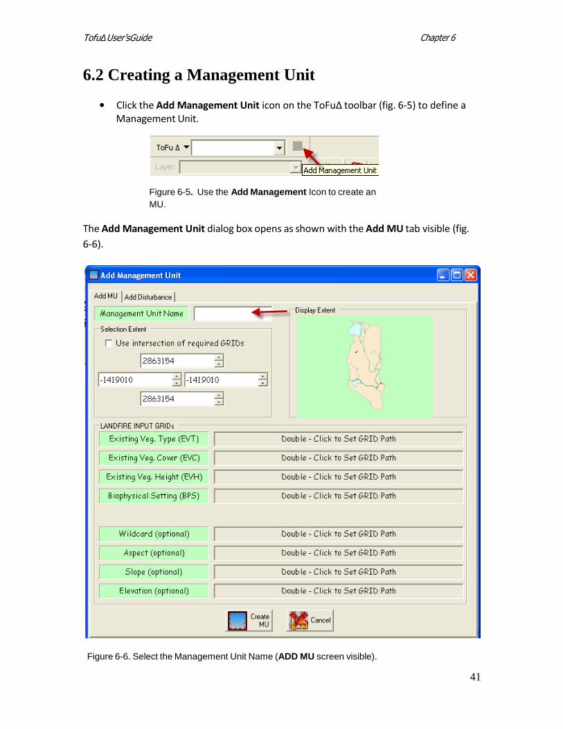
6.2 Creating a Management Unit
Click the Add Management Unit icon on the ToFuΔ toolbar (fig. 6-5) to define a Management Unit.
Figure 6-5. Use the Add Management Icon to create an
MU.
The Add Management Unit dialog box opens as shown with the Add MU tab visible (fig.
6-6).
Figure 6-6. Select the Management Unit Name (ADD MU screen visible).
42
Chapter 6 TofuΔ User’sGuide
An MU can be defined by specifying coordinates or by using the drawing rectangle.
Note: For more detailed information on specifying the extent of your MU, see
section 7.5.
To use the drawing rectangle, drag your cursor to draw an extent rectangle in the “Display Extent” window of the dialog box (fig. 6-6).
With the Add MU tab selected, type a Management Unit Name in the box provided (fig 6-6).
Note: The naming convention follows the rules of ArcMap, which means a grid
name can be no longer than 13 characters.
Check the “Use intersection of required GRIDS” box if you want to clip all grids to the extent of the specified rectangle.
Input the required data layers (EVT, EVC, EVH, and BpS) by double-clicking in
the adjacent boxes to set a grid path.
Tip: You do not have to load grids first in ArcMap; you can simply double-click in the
Add Management Unit dialog box to load grids.
Note: All four grids (EVT, EVC, EVH, and BpS) must be in the same projection.
The Wildcard selection is optional but may be useful in some situations. If the project crosses map zone boundaries, the user can create the Management Unit with required grids by map zone and then use its boundary as a wildcard to convert the boundary shapefile to a grid and thus define the area of interest. When clipped, the area of interest will be available. See section 7.5 for more information.
Enter other optional data layers if desired (Wildcard, Aspect, Slope and
Elevation). See section 7.5 for additional information on using the Wildcard option.
Note: All grids must be in the same projection.
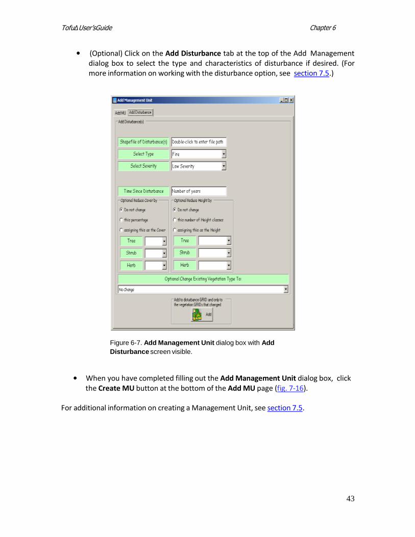
The Add Disturbance tab (fig. 6-7) is also optional and will not be discussed in detail
here. This option allows the user to select five basic types of disturbance and three
intensity levels (which correspond to the disturbance types in the LANDFIRE Reference
Database; see www.landfire.gov).
43
Chapter 6 TofuΔ User’sGuide
(Optional) Click on the Add Disturbance tab at the top of the Add Management dialog box to select the type and characteristics of disturbance if desired. (For more information on working with the disturbance option, see section 7.5.)
Figure 6-7. Add Management Unit dialog box with Add
Disturbance screen visible.
When you have completed filling out the Add Management Unit dialog box, click the Create MU button at the bottom of the Add MU page (fig. 7-16).
For additional information on creating a Management Unit, see section 7.5.
44
Chapter 6 TofuΔ User’sGuide
6.3 Working with fuel rules
The Fuel Rules window is where the bulk of the modifications will be made to spatial
data to prepare them for creation of new fuels layers for fire and fuels analysis. The
Fuel Rules dialog box has many functions and display items. For additional
information on other available options, refer to section 7.6.
The following description will progress from general to more specific steps and in the
order a typical ToFu∆ user would follow. This explanation includes, in order, the main
Fuel Rules page tabs Ruleset, Compare FM, Distribution Graph, and EVT Description)
as well as several of the more commonly used Rule input icons located in the Fuel
Rules window (Copy Rule and Add Rule).
Each EVT has a set of zone-based fuel rules. New rules can be added, edited, deleted,
or copied (see section 7.6 for more detailed information).
To continue, you will need to copy rules from another existing MU or create your own rules.
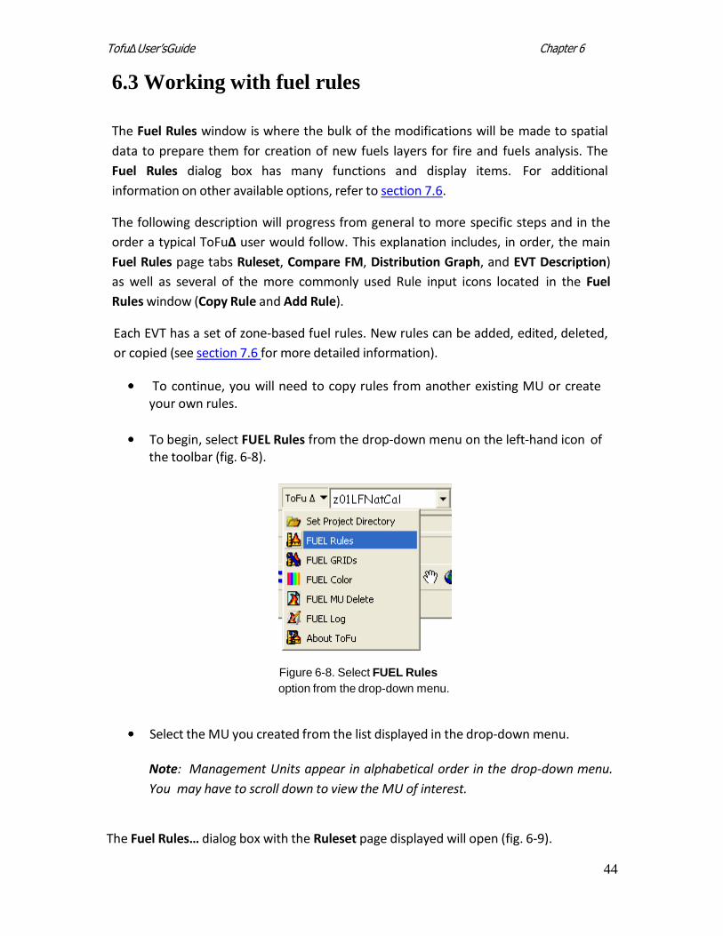
To begin, select FUEL Rules from the drop-down menu on the left-hand icon of the toolbar (fig. 6-8).
Figure 6-8. Select FUEL Rules
option from the drop-down menu.
Select the MU you created from the list displayed in the drop-down menu.
Note: Management Units appear in alphabetical order in the drop-down menu.
You may have to scroll down to view the MU of interest.
The Fuel Rules… dialog box with the Ruleset page displayed will open (fig. 6-9).
45
Chapter 6 TofuΔ User’sGuide
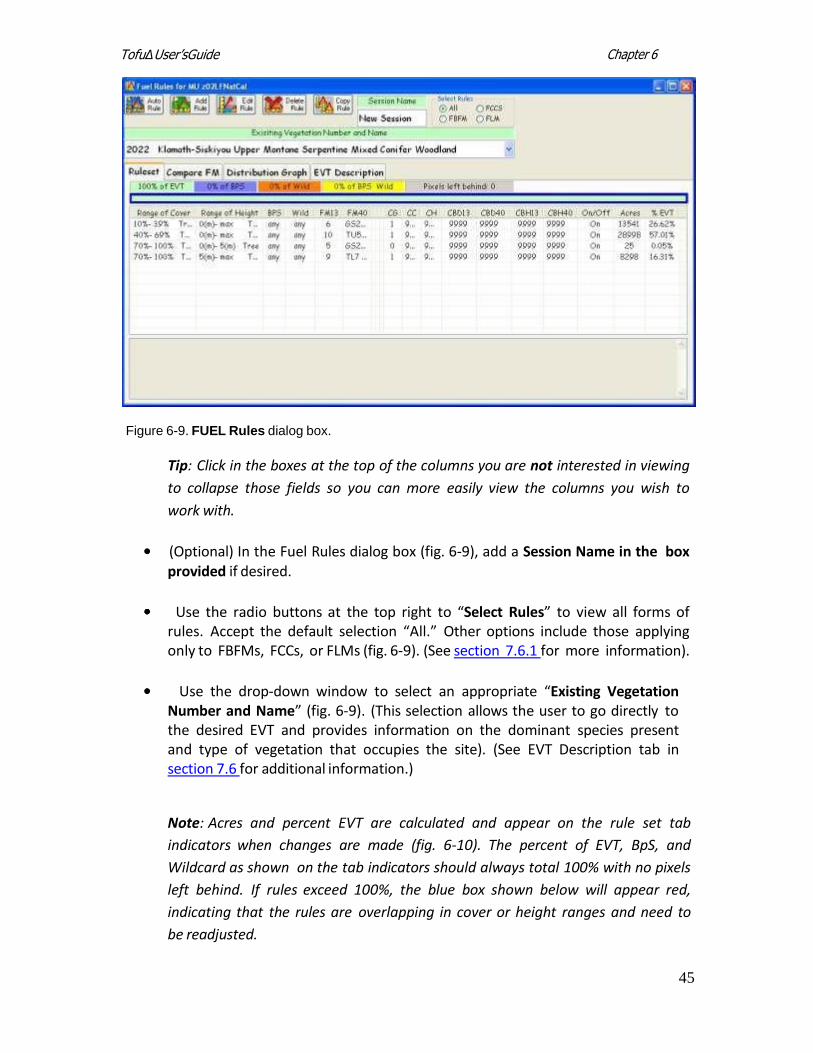
Figure 6-9. FUEL Rules dialog box.
Tip: Click in the boxes at the top of the columns you are not interested in viewing
to collapse those fields so you can more easily view the columns you wish to
work with.
(Optional) In the Fuel Rules dialog box (fig. 6-9), add a Session Name in the box provided if desired.
Use the radio buttons at the top right to “Select Rules” to view all forms of rules. Accept the default selection “All.” Other options include those applying only to FBFMs, FCCs, or FLMs (fig. 6-9). (See section 7.6.1 for more information).
Use the drop-down window to select an appropriate “Existing Vegetation Number and Name” (fig. 6-9). (This selection allows the user to go directly to the desired EVT and provides information on the dominant species present and type of vegetation that occupies the site). (See EVT Description tab in section 7.6 for additional information.)
Note: Acres and percent EVT are calculated and appear on the rule set tab
indicators when changes are made (fig. 6-10). The percent of EVT, BpS, and
Wildcard as shown on the tab indicators should always total 100% with no pixels
left behind. If rules exceed 100%, the blue box shown below will appear red,
indicating that the rules are overlapping in cover or height ranges and need to
be readjusted.
46
Chapter 6 TofuΔ User’sGuide
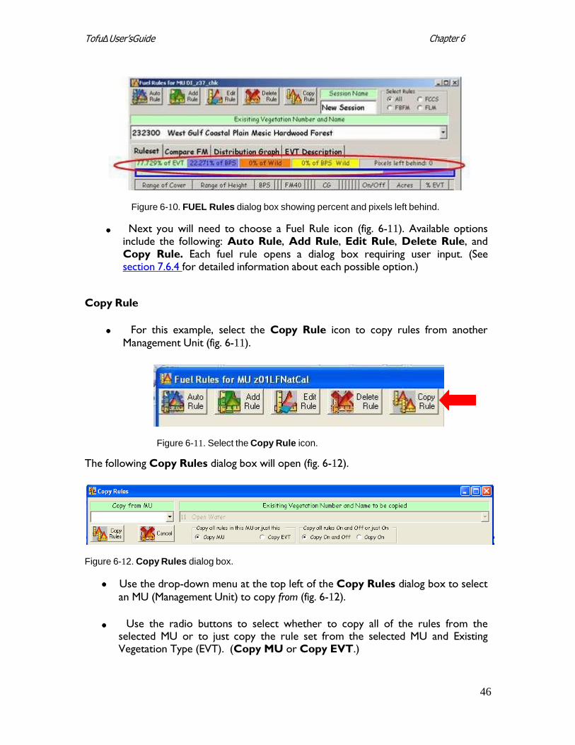
Figure 6-10. FUEL Rules dialog box showing percent and pixels left behind.
Next you will need to choose a Fuel Rule icon (fig. 6-11). Available options include the following: Auto Rule, Add Rule, Edit Rule, Delete Rule, and Copy Rule. Each fuel rule opens a dialog box requiring user input. (See section 7.6.4 for detailed information about each possible option.)
Copy Rule
For this example, select the Copy Rule icon to copy rules from another Management Unit (fig. 6-11).
Figure 6-11. Select the Copy Rule icon.
The following Copy Rules dialog box will open (fig. 6-12).
Figure 6-12. Copy Rules dialog box.
Use the drop-down menu at the top left of the Copy Rules dialog box to select
an MU (Management Unit) to copy from (fig. 6-12).
Use the radio buttons to select whether to copy all of the rules from the
selected MU or to just copy the rule set from the selected MU and Existing Vegetation Type (EVT). (Copy MU or Copy EVT.)
47
Chapter 6 TofuΔ User’sGuide
Note: Use the drop-down menu under “Existing Vegetation Number and Name
to be copied” to specify an EVT if Copy EVT is selected.
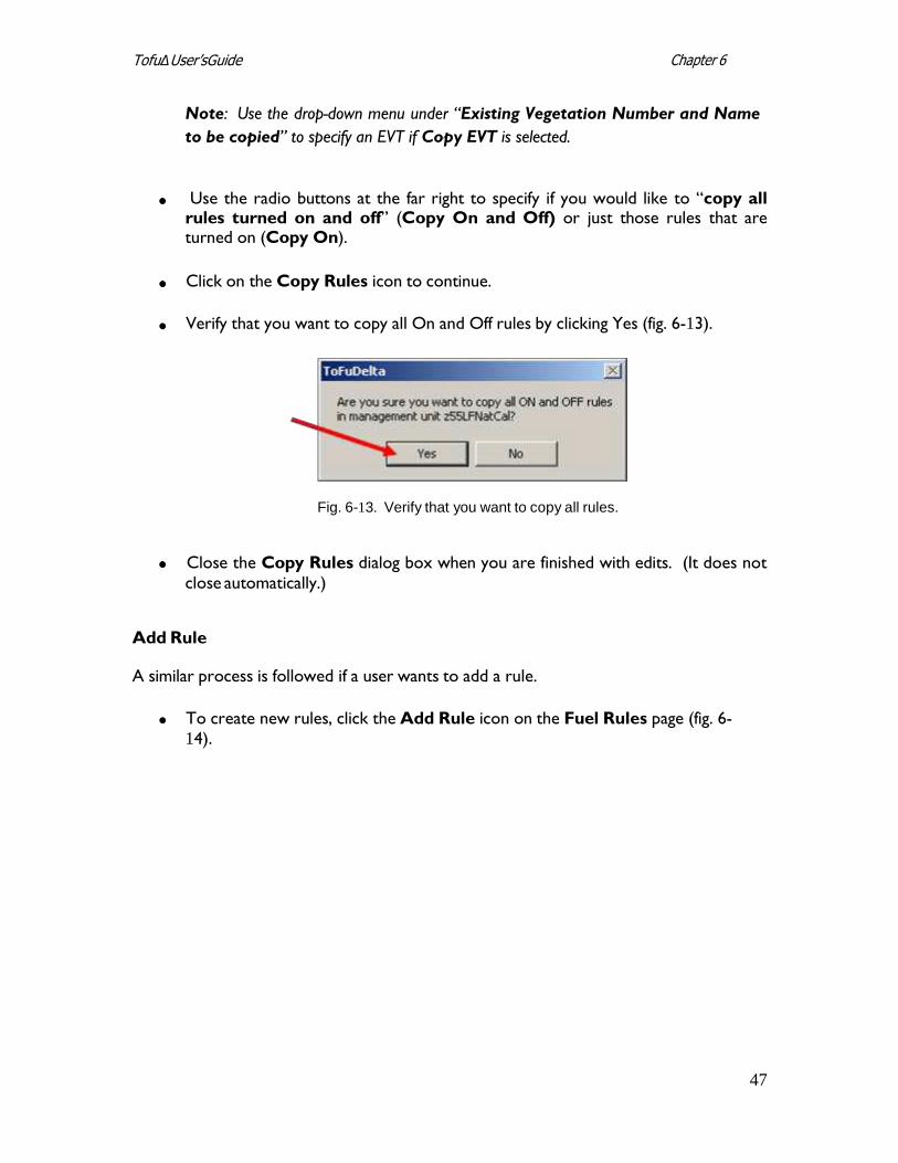
Use the radio buttons at the far right to specify if you would like to “copy all rules turned on and off” (Copy On and Off) or just those rules that are turned on (Copy On).
Click on the Copy Rules icon to continue.
Verify that you want to copy all On and Off rules by clicking Yes (fig. 6-13).
Fig. 6-13. Verify that you want to copy all rules.
Close the Copy Rules dialog box when you are finished with edits. (It does not close automatically.)
Add Rule
A similar process is followed if a user wants to add a rule.
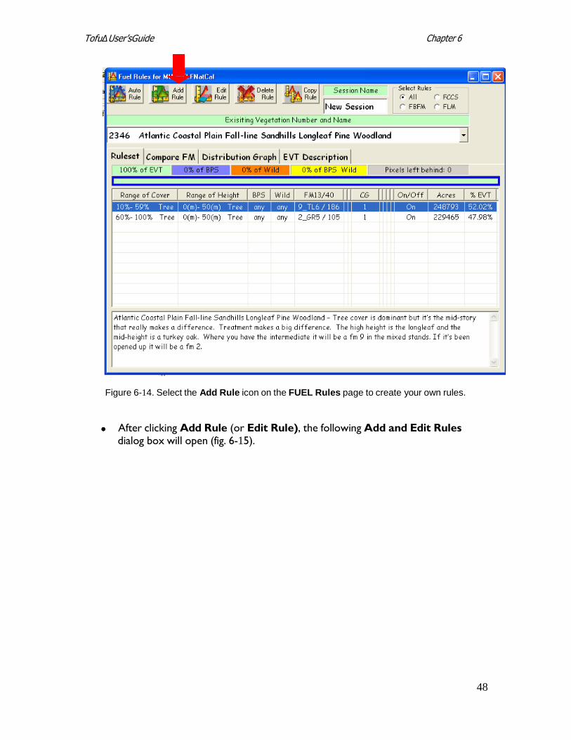
To create new rules, click the Add Rule icon on the Fuel Rules page (fig. 6- 14).
48
Chapter 6 TofuΔ User’sGuide
Figure 6-14. Select the Add Rule icon on the FUEL Rules page to create your own rules.
After clicking Add Rule (or Edit Rule), the following Add and Edit Rules dialog box will open (fig. 6-15).
49
Chapter 6 TofuΔ User’sGuide
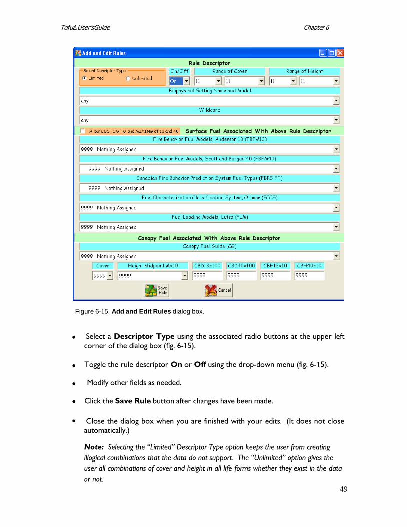
Figure 6-15. Add and Edit Rules dialog box.
Select a Descriptor Type using the associated radio buttons at the upper left
corner of the dialog box (fig. 6-15).
Toggle the rule descriptor On or Off using the drop-down menu (fig. 6-15).
Modify other fields as needed.
Click the Save Rule button after changes have been made.
Close the dialog box when you are finished with your edits. (It does not close automatically.)
Note: Selecting the “Limited” Descriptor Type option keeps the user from creating
illogical combinations that the data do not support. The “Unlimited” option gives the
user all combinations of cover and height in all life forms whether they exist in the data
or not.
50
Chapter 6 TofuΔ User’sGuide
Tip: Use the ideas shown in figure 7-24 to improve your space management.
Other fuel rule input options are also available (Auto Rule, Edit Rule, and Delete
Rule). See section 7.6.4 for detailed information describing these options.
6.4 Evaluating surface and canopy fuel assignments
The next step is to evaluate both surface and canopy fuel assignments.
Open the Fuel Rules dialog box to the Ruleset page. Use the drop-down
menu to select and highlight EVTs to account for all pixels. (See section 7.6.3 for additional information on this subject.)
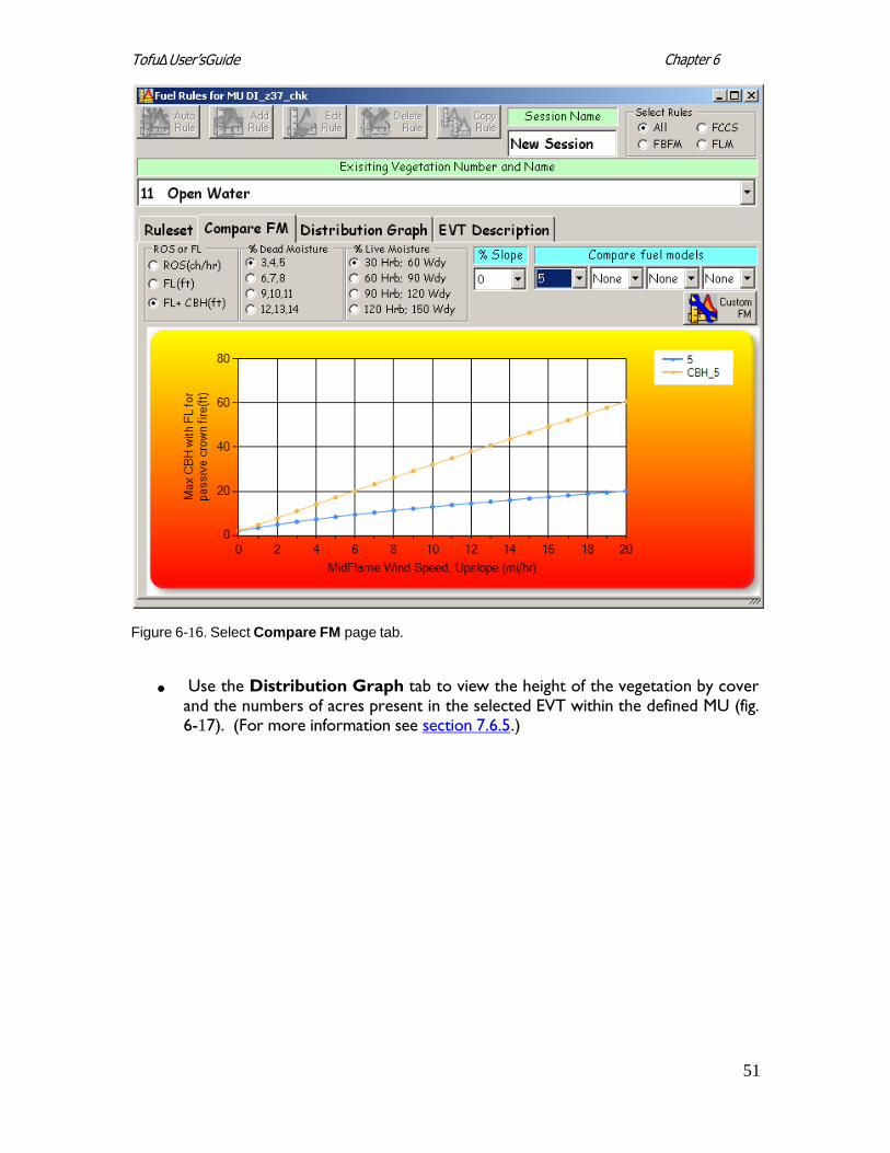
Select the Compare FM tab on the Fuel Rules screen to compare the
required canopy base heights (CBH) needed for torching and crowning fire initiation (fig. 6-16). (For additional information refer to section 7.6.5.)
51
Chapter 6 TofuΔ User’sGuide
Figure 6-16. Select Compare FM page tab.
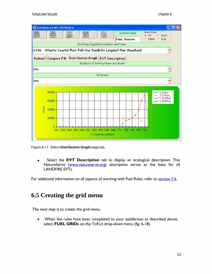
Use the Distribution Graph tab to view the height of the vegetation by cover
and the numbers of acres present in the selected EVT within the defined MU (fig. 6-17). (For more information see section 7.6.5.)
52
Chapter 6 TofuΔ User’sGuide
Figure 6-17. Select Distribution Graph page tab.
Select the EVT Description tab to display an ecological description. This
NatureServe (www.natureserve.org) description serves as the basis for all LANDFIRE EVTs.
For additional information on all aspects of working with Fuel Rules, refer to section 7.6.
6.5 Creating the grid menu
The next step is to create the grid menu.
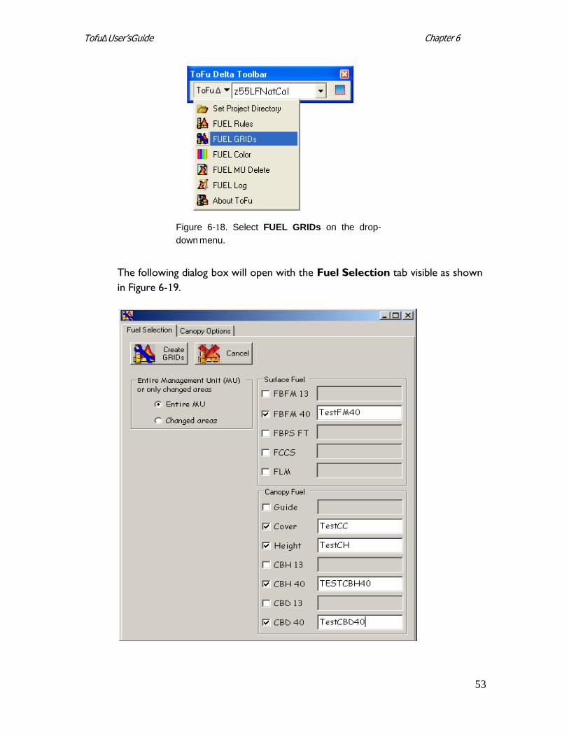
When the rules have been completed to your satisfaction as described above,
select FUEL GRIDs on the ToFu∆ drop-down menu (fig. 6-18).
53
Chapter 6 TofuΔ User’sGuide
Figure 6-18. Select FUEL GRIDs on the drop-
down menu.
The following dialog box will open with the Fuel Selection tab visible as shown
in Figure 6-19.
54
Chapter 6 TofuΔ User’sGuide
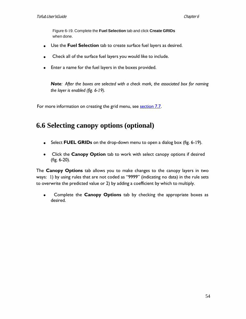
Figure 6-19. Complete the Fuel Selection tab and click Create GRIDs
when done.
Use the Fuel Selection tab to create surface fuel layers as desired.
Check all of the surface fuel layers you would like to include.
Enter a name for the fuel layers in the boxes provided.
Note: After the boxes are selected with a check mark, the associated box for naming
the layer is enabled (fig. 6-19).
For more information on creating the grid menu, see section 7.7.
6.6 Selecting canopy options (optional)
Select FUEL GRIDs on the drop-down menu to open a dialog box (fig. 6-19).
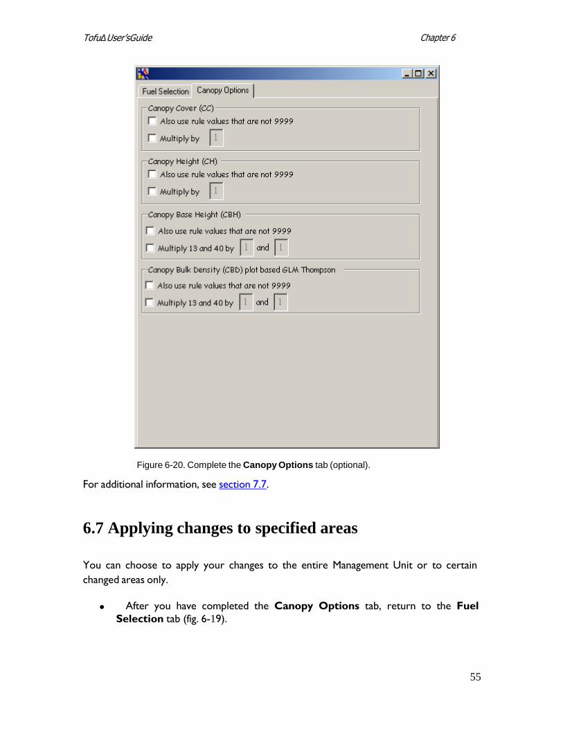
Click the Canopy Option tab to work with select canopy options if desired (fig. 6-20).
The Canopy Options tab allows you to make changes to the canopy layers in two
ways: 1) by using rules that are not coded as “9999” (indicating no data) in the rule sets
to overwrite the predicted value or 2) by adding a coefficient by which to multiply.
Complete the Canopy Options tab by checking the appropriate boxes as
desired.
55
Chapter 6 TofuΔ User’sGuide
Figure 6-20. Complete the Canopy Options tab (optional).
For additional information, see section 7.7.
6.7 Applying changes to specified areas
You can choose to apply your changes to the entire Management Unit or to certain
changed areas only.
After you have completed the Canopy Options tab, return to the Fuel
Selection tab (fig. 6-19).
56
Chapter 6 TofuΔ User’sGuide
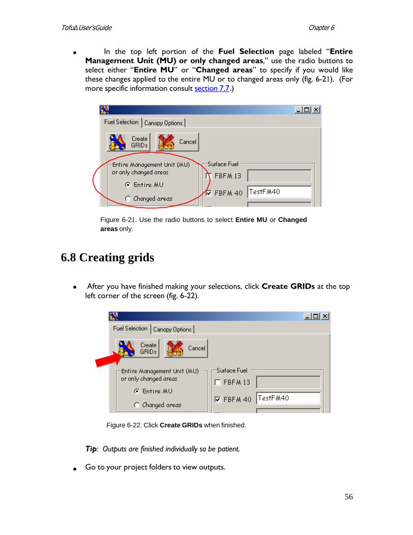
In the top left portion of the Fuel Selection page labeled “Entire Management Unit (MU) or only changed areas,” use the radio buttons to select either “Entire MU” or “Changed areas” to specify if you would like these changes applied to the entire MU or to changed areas only (fig. 6-21). (For more specific information consult section 7.7.)
Figure 6-21. Use the radio buttons to select Entire MU or Changed
areas only.
6.8 Creating grids
After you have finished making your selections, click Create GRIDs at the top
left corner of the screen (fig. 6-22).
Figure 6-22. Click Create GRIDs when finished.
Tip: Outputs are finished individually so be patient.
Go to your project folders to view outputs.
57
Chapter 6 TofuΔ User’sGuide
6.9 Adjusting rule sets
At this point, you can adjust rule sets if necessary. If changes are needed, go back to the
rules, make your changes, and then create the grids again.
6.10 0 Evaluating outputs
Finally, evaluate your outputs. Your edited outputs should now better reflect expected
fire behavior and fuels characteristics for your area.
58
Chapter 7 ToFu∆ User’s Guide
Chapter 7: Using ToFu∆
7.1 The ToFu∆ toolbar 7.2 Creating a new project 7.3 Loading data 7.4 Workspace settings
7.5 Management Units
7.6 Fuel rules
7.6.1 Fuel rule header selections 7.6.2 Column headers 7.6.3 Tab indicators 7.6.4 Rule input options
7.6.5 Fuel rule page tabs
7.7 Creating new grids
7.8 Fuel grid color palette 7.9 Deleting fuel Management Units
7.10 log
7.11 About ToFu∆ 7.12 7.12 Help
This chapter describes ToFu∆’s functionality in detail. Each available option is
described in a sequential order wherever possible. If you would prefer to see an
overview of generalized tool operation, refer to Chapter 6. Because ToFu∆ offers
many options, you may prefer to skip to sections of particular interest.
7.1 The ToFu∆ toolbar
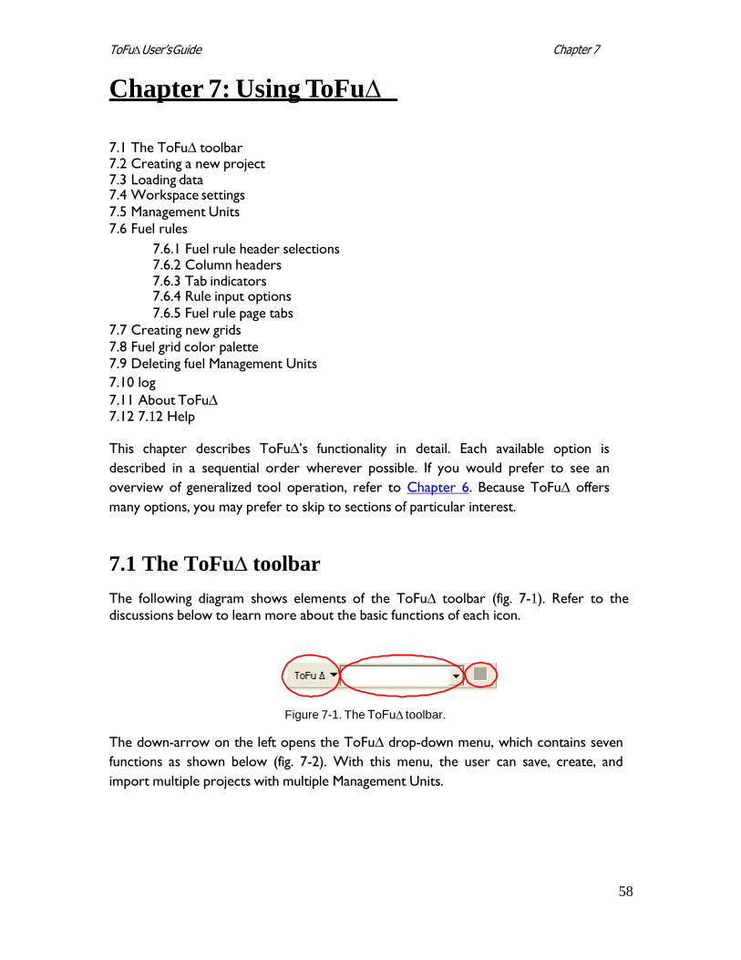
The following diagram shows elements of the ToFu∆ toolbar (fig. 7-1). Refer to the discussions below to learn more about the basic functions of each icon.
Figure 7-1. The ToFu∆ toolbar.
The down-arrow on the left opens the ToFu∆ drop-down menu, which contains seven
functions as shown below (fig. 7-2). With this menu, the user can save, create, and
import multiple projects with multiple Management Units.
59
Chapter 7 ToFu∆ User’s Guide
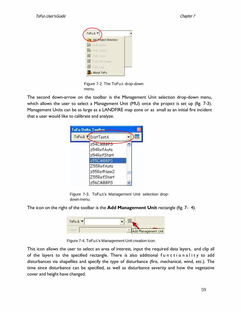
Figure 7-2. The ToFu∆ drop-down
menu.
The second down-arrow on the toolbar is the Management Unit selection drop-down menu,
which allows the user to select a Management Unit (MU) once the project is set up (fig. 7-3).
Management Units can be as large as a LANDFIRE map zone or as small as an initial fire incident
that a user would like to calibrate and analyze.
Figure 7-3. ToFu∆’s Management Unit selection drop-
down menu.
The icon on the right of the toolbar is the Add Management Unit rectangle (fig. 7- 4).
Figure 7-4. ToFu∆’s Management Unit creation icon.
This icon allows the user to select an area of interest, input the required data layers, and clip all
of the layers to the specified rectangle. There is also additional f u n c t i o n a l i t y to add
disturbances via shapefiles and specify the type of disturbance (fire, mechanical, wind, etc.). The
time since disturbance can be specified, as well as disturbance severity and how the vegetative
cover and height have changed.
60
Chapter 7 ToFu∆ User’s Guide
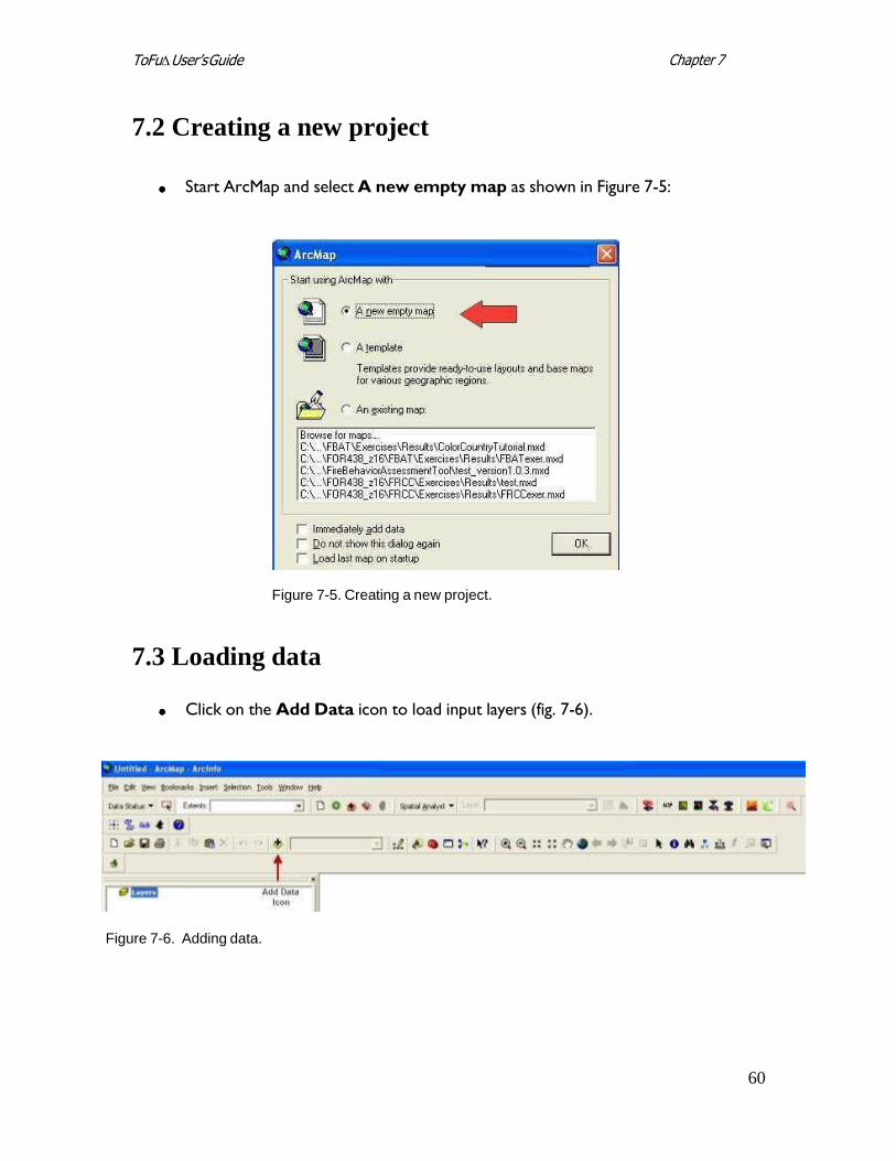
7.2 Creating a new project
Start ArcMap and select A new empty map as shown in Figure 7-5:
Figure 7-5. Creating a new project.
7.3 Loading data
Click on the Add Data icon to load input layers (fig. 7-6).
Figure 7-6. Adding data.
61
Chapter 7 ToFu∆ User’s Guide
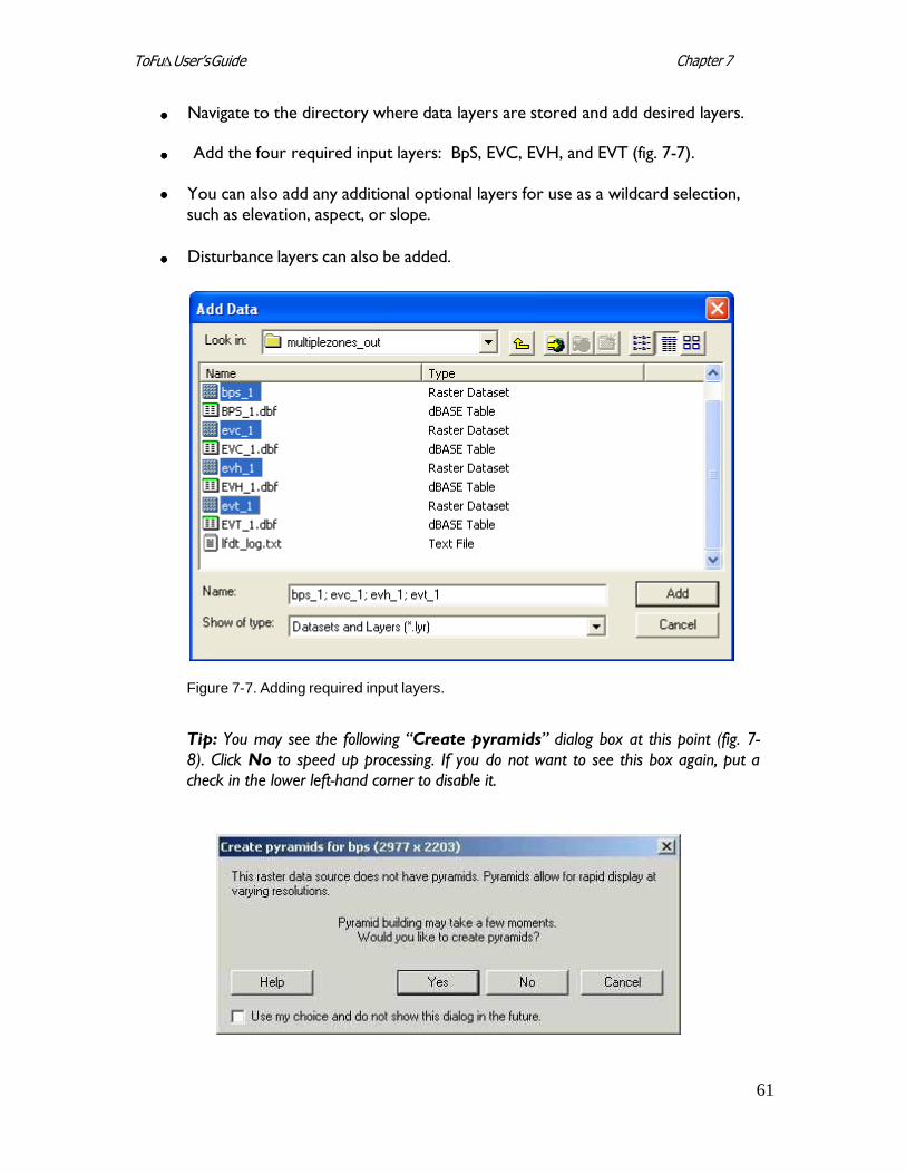
Navigate to the directory where data layers are stored and add desired layers.
Add the four required input layers: BpS, EVC, EVH, and EVT (fig. 7-7).
You can also add any additional optional layers for use as a wildcard selection,
such as elevation, aspect, or slope.
Disturbance layers can also be added.
Figure 7-7. Adding required input layers.
Tip: You may see the following “Create pyramids” dialog box at this point (fig. 7-
8). Click No to speed up processing. If you do not want to see this box again, put a check in the lower left-hand corner to disable it.
62
Chapter 7 ToFu∆ User’s Guide
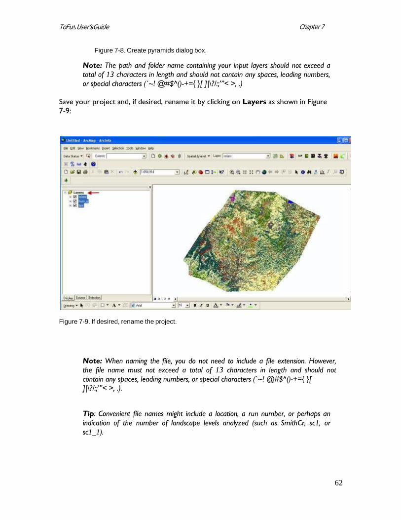
Figure 7-8. Create pyramids dialog box.
Note: The path and folder name containing your input layers should not exceed a total of 13 characters in length and should not contain any spaces, leading numbers,
or special characters (`~! @#$^()-+={ }[ ]|\?/:;”’< >, .)
Save your project and, if desired, rename it by clicking on Layers as shown in Figure
7-9:
Figure 7-9. If desired, rename the project.
Note: When naming the file, you do not need to include a file extension. However, the file name must not exceed a total of 13 characters in length and should not
contain any spaces, leading numbers, or special characters (`~! @#$^()-+={ }[ ]|\?/:;”’< >, .).
Tip: Convenient file names might include a location, a run number, or perhaps an
indication of the number of landscape levels analyzed (such as SmithCr, sc1, or
sc1_1).
63
Chapter 7 ToFu∆ User’s Guide
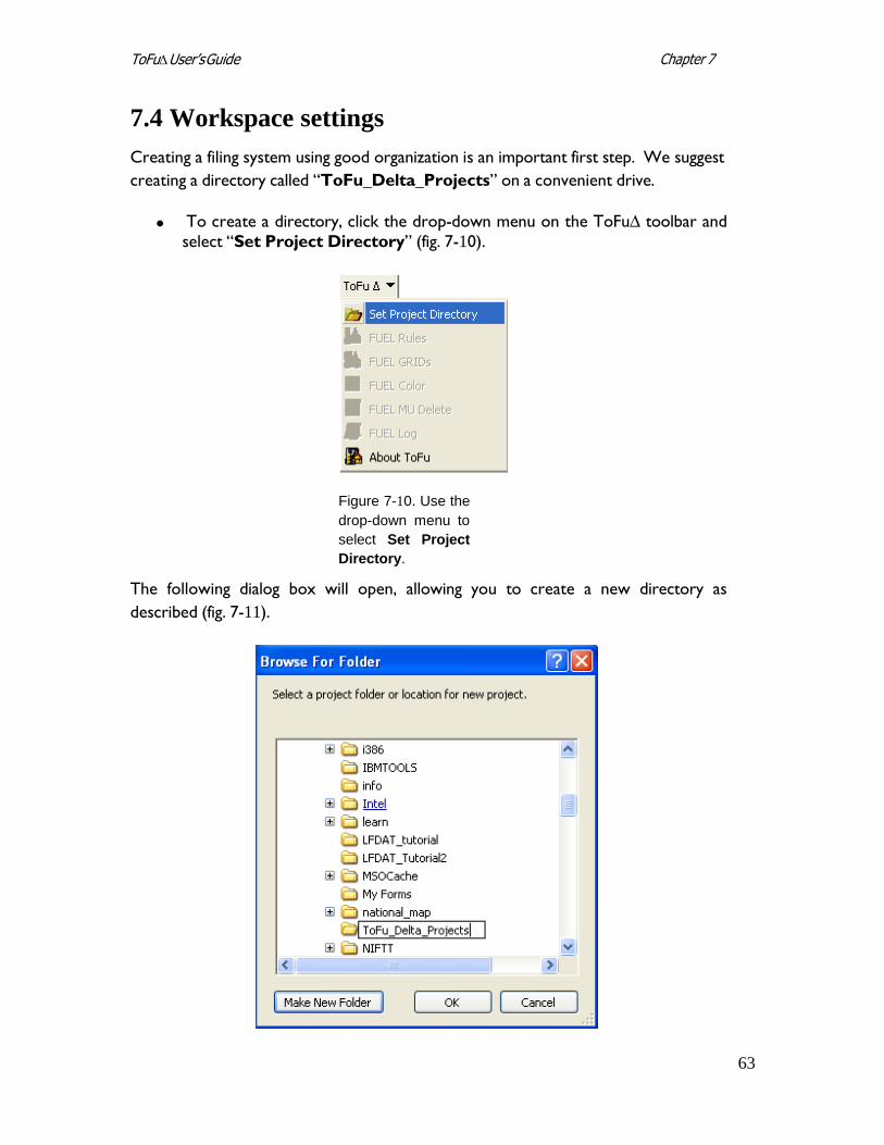
7.4 Workspace settings
Creating a filing system using good organization is an important first step. We suggest
creating a directory called “ToFu_Delta_Projects” on a convenient drive.
To create a directory, click the drop-down menu on the ToFu∆ toolbar and
select “Set Project Directory” (fig. 7-10).
Figure 7-10. Use the
drop-down menu to
select Set Project
Directory.
The following dialog box will open, allowing you to create a new directory as
described (fig. 7-11).
64
Chapter 7 ToFu∆ User’s Guide
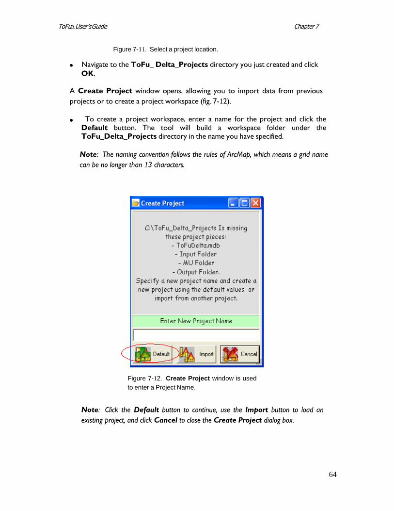
Figure 7-11. Select a project location.
Navigate to the ToFu_ Delta_Projects directory you just created and click
OK.
A Create Project window opens, allowing you to import data from previous
projects or to create a project workspace (fig. 7-12).
To create a project workspace, enter a name for the project and click the Default button. The tool will build a workspace folder under the ToFu_Delta_Projects directory in the name you have specified.
Note: The naming convention follows the rules of ArcMap, which means a grid name
can be no longer than 13 characters.
Figure 7-12. Create Project window is used
to enter a Project Name.
Note: Click the Default button to continue, use the Import button to load an
existing project, and click Cancel to close the Create Project dialog box.
65
Chapter 7 ToFu∆ User’s Guide
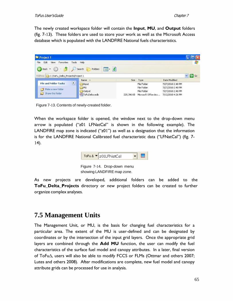
The newly created workspace folder will contain the Input, MU, and Output folders
(fig. 7-13). These folders are used to store your work as well as the Microsoft Access
database which is populated with the LANDFIRE National fuels characteristics.
Figure 7-13. Contents of newly-created folder.
When the workspace folder is opened, the window next to the drop-down menu
arrow is populated (“z01 LFNatCal” is shown in the following example). The
LANDFIRE map zone is indicated (“z01”) as well as a designation that the information
is for the LANDFIRE National Calibrated fuel characteristic data (“LFNatCal”) (fig. 7-
14).
Figure 7-14. Drop-down menu
showing LANDFIRE map zone.
As new projects are developed, additional folders can be added to the
ToFu_Delta_Projects directory or new project folders can be created to further
organize complex analyses.
7.5 Management Units
The Management Unit, or MU, is the basis for changing fuel characteristics for a
particular area. The extent of the MU is user-defined and can be designated by
coordinates or by the intersection of the input grid layers. Once the appropriate grid
layers are combined through the Add MU function, the user can modify the fuel
characteristics of the surface fuel model and canopy attributes. In a later, final version
of ToFu∆, users will also be able to modify FCCS or FLMs (Ottmar and others 2007;
Lutes and others 2008). After modifications are complete, new fuel model and canopy
attribute grids can be processed for use in analysis.
66
Chapter 7 ToFu∆ User’s Guide
Note: The default data set includes MUs created for all LANDFIRE map zones
except Alaska and Hawaii. These zones exist in relational Microsoft Access database
form only and not as spatial grids in the MU folder. As new MUs are created, they
will consist of a combined grid of the four mandatory grid layers from the LANDFIRE
data set and any optional grid layers the user inputs. They will reside in the MU
folder.
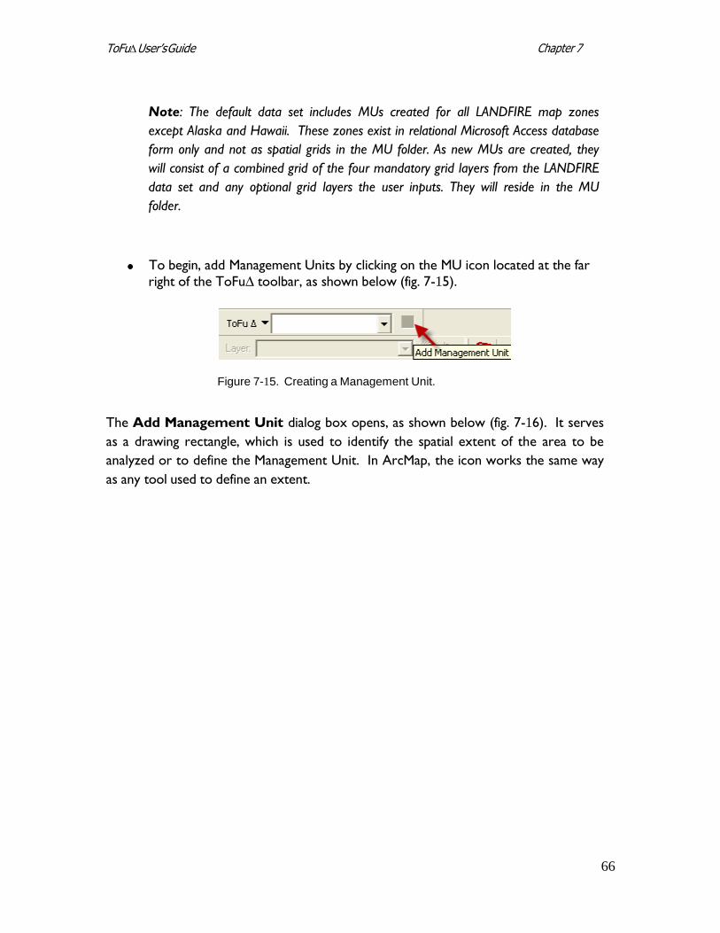
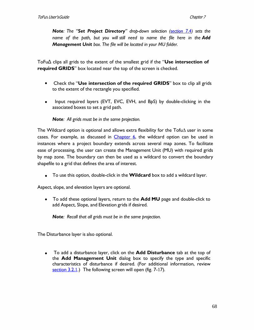
To begin, add Management Units by clicking on the MU icon located at the far
right of the ToFu∆ toolbar, as shown below (fig. 7-15).
Figure 7-15. Creating a Management Unit.
The Add Management Unit dialog box opens, as shown below (fig. 7-16). It serves
as a drawing rectangle, which is used to identify the spatial extent of the area to be
analyzed or to define the Management Unit. In ArcMap, the icon works the same way
as any tool used to define an extent.
67
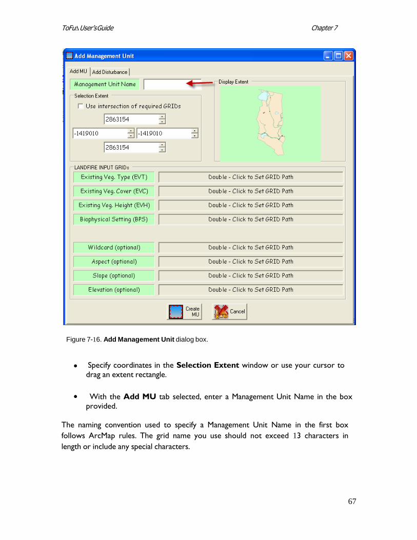
Chapter 7 ToFu∆ User’s Guide
Figure 7-16. Add Management Unit dialog box.
Specify coordinates in the Selection Extent window or use your cursor to drag an extent rectangle.
With the Add MU tab selected, enter a Management Unit Name in the box
provided. The naming convention used to specify a Management Unit Name in the first box
follows ArcMap rules. The grid name you use should not exceed 13 characters in
length or include any special characters.
68
Chapter 7 ToFu∆ User’s Guide
Note: The “Set Project Directory” drop-down selection (section 7.4) sets the
name of the path, but you will still need to name the file here in the Add
Management Unit box. The file will be located in your MU folder.
ToFuΔ clips all grids to the extent of the smallest grid if the “Use intersection of
required GRIDS” box located near the top of the screen is checked.
Check the “Use intersection of the required GRIDS” box to clip all grids
to the extent of the rectangle you specified.
Input required layers (EVT, EVC, EVH, and BpS) by double-clicking in the
associated boxes to set a grid path.
Note: All grids must be in the same projection.
The Wildcard option is optional and allows extra flexibility for the Tofu∆ user in some
cases. For example, as discussed in Chapter 6, the wildcard option can be used in
instances where a project boundary extends across several map zones. To facilitate
ease of processing, the user can create the Management Unit (MU) with required grids
by map zone. The boundary can then be used as a wildcard to convert the boundary
shapefile to a grid that defines the area of interest.
To use this option, double-click in the Wildcard box to add a wildcard layer.
Aspect, slope, and elevation layers are optional.
To add these optional layers, return to the Add MU page and double-click to add Aspect, Slope, and Elevation grids if desired.
Note: Recall that all grids must be in the same projection.
The Disturbance layer is also optional.
To add a disturbance layer, click on the Add Disturbance tab at the top of
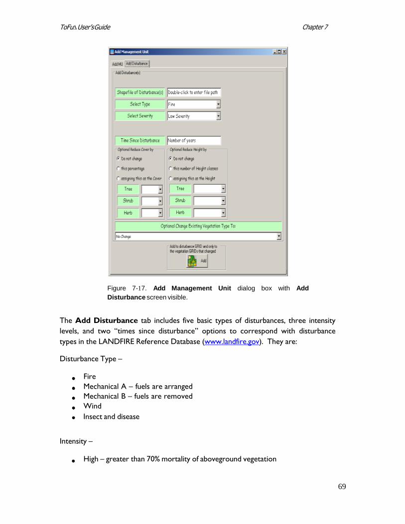
the Add Management Unit dialog box to specify the type and specific characteristics of disturbance if desired. (For additional information, review section 3.2.1.) The following screen will open (fig. 7-17).
69
Chapter 7 ToFu∆ User’s Guide
Figure 7-17. Add Management Unit dialog box with Add
Disturbance screen visible.
The Add Disturbance tab includes five basic types of disturbances, three intensity
levels, and two “times since disturbance” options to correspond with disturbance
types in the LANDFIRE Reference Database (www.landfire.gov). They are:
Disturbance Type –
Fire
Mechanical A – fuels are arranged
Mechanical B – fuels are removed
Wind
Insect and disease
Intensity –
High – greater than 70% mortality of aboveground vegetation
70
Chapter 7 ToFu∆ User’s Guide
Medium – greater than 25% but less than 70% mortality of aboveground
vegetation Low – less than 25% mortality of aboveground vegetation
Time Since Disturbance –
0-5 years (5-10 years in the western U.S.)
0-3 years (3-10 years in the southeastern U.S.)
To use the Disturbance option:
Double-click in the box to the right of “Shapefile of Disturbance(s)” at the top of the screen to specify a particular shapefile. The shapefile you select must be in the same project as the MU.
Next, select a disturbance type (“Select Type”) using the drop-down menu
provided. Possible options include: fire, mechanical A and B, wind, and insect and disease.
Select the severity of disturbance (“Select Severity”) using the drop-down
menu. Options include: high, medium, and low.
Enter “Time Since Disturbance,” expressed in years, in the box provided.
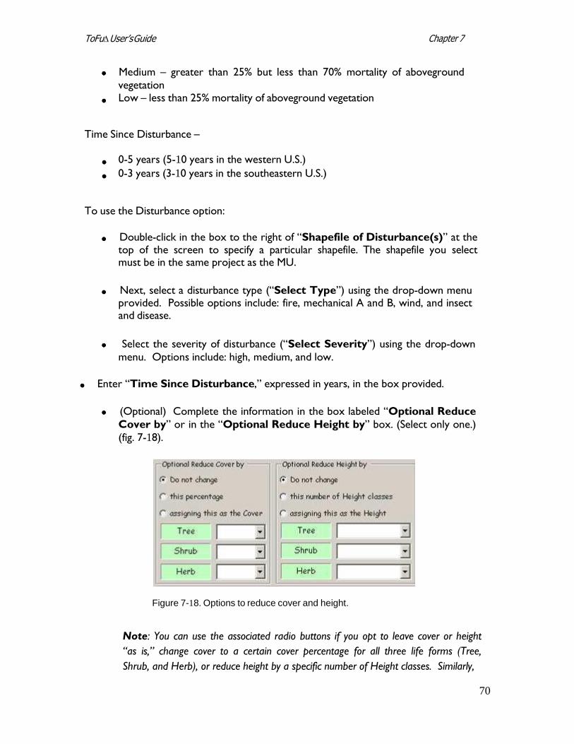
(Optional) Complete the information in the box labeled “Optional Reduce
Cover by” or in the “Optional Reduce Height by” box. (Select only one.)
(fig. 7-18).
Figure 7-18. Options to reduce cover and height.
Note: You can use the associated radio buttons if you opt to leave cover or height
“as is,” change cover to a certain cover percentage for all three life forms (Tree,
Shrub, and Herb), or reduce height by a specific number of Height classes. Similarly,
71
Chapter 7 ToFu∆ User’s Guide
you can use the spinner boxes to assign specific values as Cover or to assign specific
values as Height.
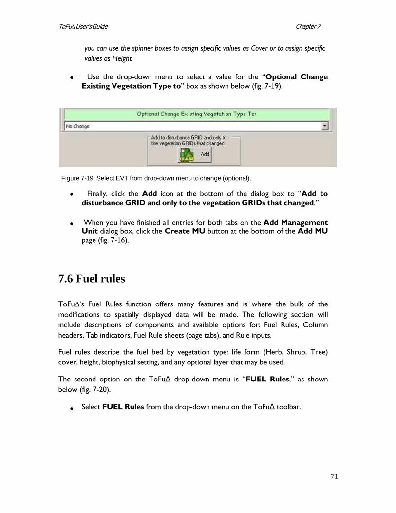
Use the drop-down menu to select a value for the “Optional Change
Existing Vegetation Type to” box as shown below (fig. 7-19).
Figure 7-19. Select EVT from drop-down menu to change (optional).
Finally, click the Add icon at the bottom of the dialog box to “Add to disturbance GRID and only to the vegetation GRIDs that changed.”
When you have finished all entries for both tabs on the Add Management
Unit dialog box, click the Create MU button at the bottom of the Add MU page (fig. 7-16).
7.6 Fuel rules
ToFu∆’s Fuel Rules function offers many features and is where the bulk of the
modifications to spatially displayed data will be made. The following section will
include descriptions of components and available options for: Fuel Rules, Column
headers, Tab indicators, Fuel Rule sheets (page tabs), and Rule inputs.
Fuel rules describe the fuel bed by vegetation type: life form (Herb, Shrub, Tree)
cover, height, biophysical setting, and any optional layer that may be used.
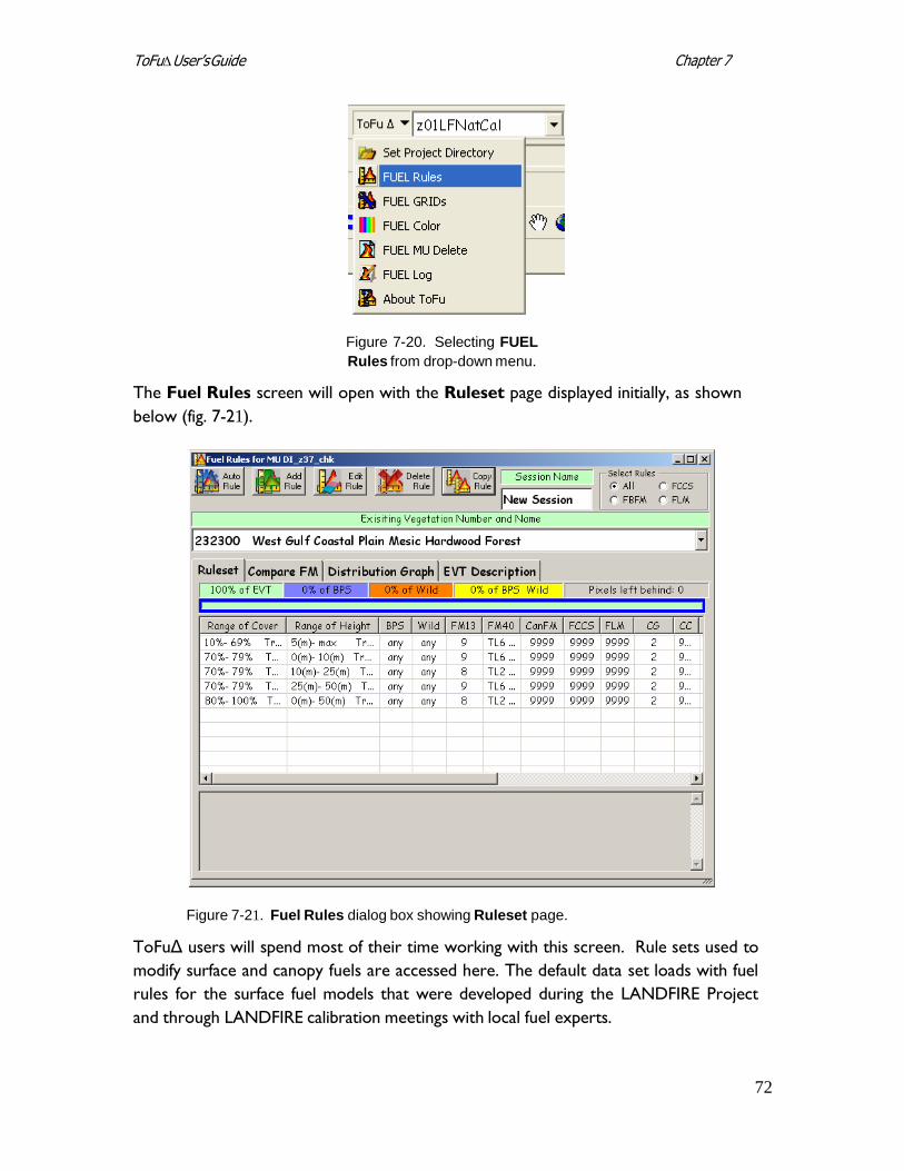
The second option on the ToFuΔ drop-down menu is “FUEL Rules,” as shown
below (fig. 7-20).
Select FUEL Rules from the drop-down menu on the ToFuΔ toolbar.
72
Chapter 7 ToFu∆ User’s Guide
Figure 7-20. Selecting FUEL
Rules from drop-down menu.
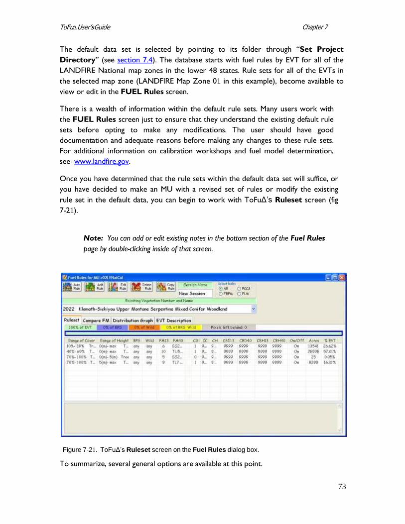
The Fuel Rules screen will open with the Ruleset page displayed initially, as shown
below (fig. 7-21).
Figure 7-21. Fuel Rules dialog box showing Ruleset page.
ToFuΔ users will spend most of their time working with this screen. Rule sets used to
modify surface and canopy fuels are accessed here. The default data set loads with fuel
rules for the surface fuel models that were developed during the LANDFIRE Project
and through LANDFIRE calibration meetings with local fuel experts.
73
Chapter 7 ToFu∆ User’s Guide
The default data set is selected by pointing to its folder through “Set Project
Directory” (see section 7.4). The database starts with fuel rules by EVT for all of the
LANDFIRE National map zones in the lower 48 states. Rule sets for all of the EVTs in
the selected map zone (LANDFIRE Map Zone 01 in this example), become available to
view or edit in the FUEL Rules screen.
There is a wealth of information within the default rule sets. Many users work with
the FUEL Rules screen just to ensure that they understand the existing default rule
sets before opting to make any modifications. The user should have good
documentation and adequate reasons before making any changes to these rule sets.
For additional information on calibration workshops and fuel model determination,
see www.landfire.gov.
Once you have determined that the rule sets within the default data set will suffice, or
you have decided to make an MU with a revised set of rules or modify the existing
rule set in the default data, you can begin to work with ToFuΔ’s Ruleset screen (fig
7-21).
Note: You can add or edit existing notes in the bottom section of the Fuel Rules
page by double-clicking inside of that screen.
Figure 7-21. ToFuΔ’s Ruleset screen on the Fuel Rules dialog box.
To summarize, several general options are available at this point.
74
Chapter 7 ToFu∆ User’s Guide
If the default data set is reviewed and determined to be usable with no further modifications, a grid of the 13 or 40 Fuel Behavior Fuel Models (FBFM) and grids of canopy attributes (see Chapter 3) can be made for use in fire potential and simulation software such as FARSITE or FlamMap (see “Creating new grids” in section 7.7).
If the edits are made to the default database (see “Rule input options” in
section 7.6.4 later in this chapter) then grids of the FBFMs and/or canopy
attributes can be made. For additional information on this subject, see
“Creating new grids” in section 7.7.
If an MU was created for the purpose of developing rule sets for fuel
characteristics when the MU is selected in the MU window (no fuels layer is
added in as a wildcard) and the FUEL Rules selection is made on the ToFuΔ
drop-down menu, the FUEL Rules window will open.
A “9999,” indicating that there are no data, will be visible where all of the rule set
information should be displayed. At this point, the user will need to copy a rule
(“Copy Rule”), use auto rule (“Auto Rule”), create a rule through editing (“Edit
Rule”), or add a rule (“Add Rule”) for the EVC, EVH, BpS, FBFM, and canopy
attributes for each rule set in each EVT desired in the MU.
Note: Other options for editing rules exist and are available through ToFuΔ.
However, the options described above represent the most common functions in
current use.
7.6.1 Fuel rule header selections
The following header selection components are found at the top of the Fuel
Rules page (fig 7-22).
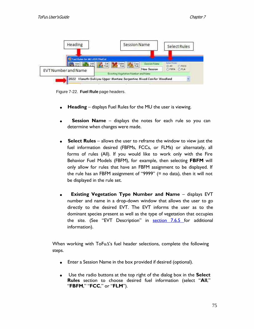
75
Chapter 7 ToFu∆ User’s Guide
Figure 7-22. Fuel Rule page headers.
Heading – displays Fuel Rules for the MU the user is viewing.
Session Name – displays the notes for each rule so you can
determine when changes were made.
Select Rules – allows the user to reframe the window to view just the
fuel information desired (FBFMs, FCCs, or FLMs) or alternately, all
forms of rules (All). If you would like to work only with the Fire
Behavior Fuel Models (FBFM), for example, then selecting FBFM will
only allow for rules that have an FBFM assignment to be displayed. If
the rule has an FBFM assignment of “9999” (= no data), then it will not
be displayed in the rule set.
Existing Vegetation Type Number and Name – displays EVT
number and name in a drop-down window that allows the user to go
directly to the desired EVT. The EVT informs the user as to the
dominant species present as well as the type of vegetation that occupies
the site. (See “EVT Description” in section 7.6.5 for additional
information).
When working with ToFu∆’s fuel header selections, complete the following
steps.
Enter a Session Name in the box provided if desired (optional).
Use the radio buttons at the top right of the dialog box in the Select
Rules section to choose desired fuel information (select “All,” “FBFM,” “FCC,” or “FLM”).
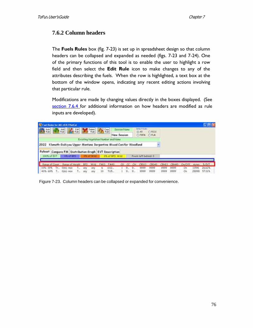
76
Chapter 7 ToFu∆ User’s Guide
7.6.2 Column headers
The Fuels Rules box (fig. 7-23) is set up in spreadsheet design so that column
headers can be collapsed and expanded as needed (figs. 7-23 and 7-24). One
of the primary functions of this tool is to enable the user to highlight a row
field and then select the Edit Rule icon to make changes to any of the
attributes describing the fuels. When the row is highlighted, a text box at the
bottom of the window opens, indicating any recent editing actions involving
that particular rule.
Modifications are made by changing values directly in the boxes displayed. (See
section 7.6.4 for additional information on how headers are modified as rule
inputs are developed).
Figure 7-23. Column headers can be collapsed or expanded for convenience.
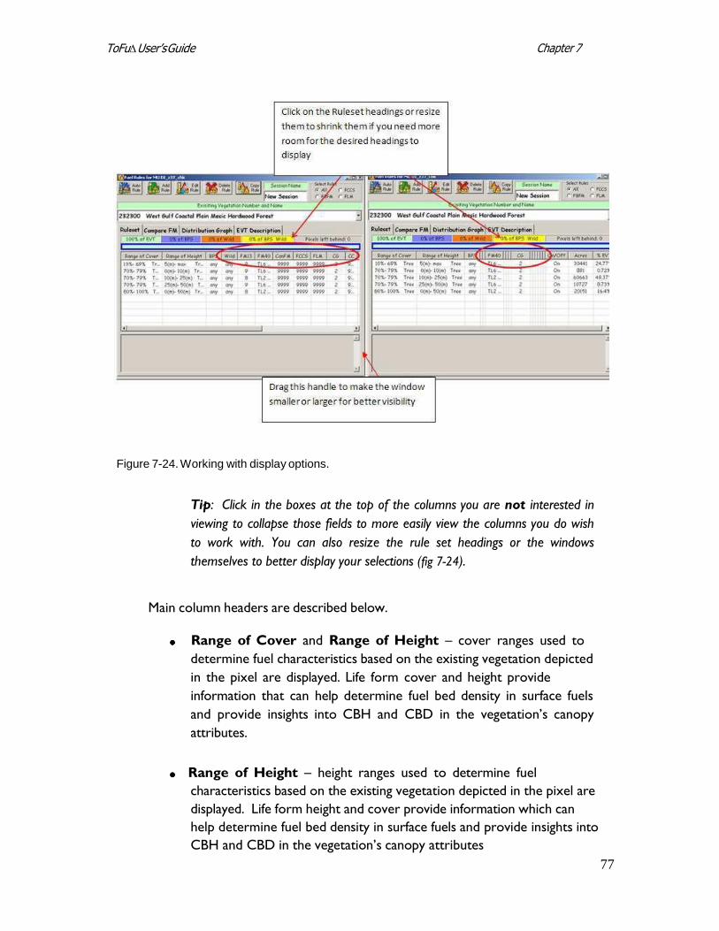
77
Chapter 7 ToFu∆ User’s Guide
Figure 7-24. Working with display options.
Tip: Click in the boxes at the top of the columns you are not interested in
viewing to collapse those fields to more easily view the columns you do wish
to work with. You can also resize the rule set headings or the windows
themselves to better display your selections (fig 7-24).
Main column headers are described below.
Range of Cover and Range of Height – cover ranges used to
determine fuel characteristics based on the existing vegetation depicted
in the pixel are displayed. Life form cover and height provide
information that can help determine fuel bed density in surface fuels
and provide insights into CBH and CBD in the vegetation’s canopy
attributes.
Range of Height – height ranges used to determine fuel
characteristics based on the existing vegetation depicted in the pixel are
displayed. Life form height and cover provide information which can
help determine fuel bed density in surface fuels and provide insights into
CBH and CBD in the vegetation’s canopy attributes
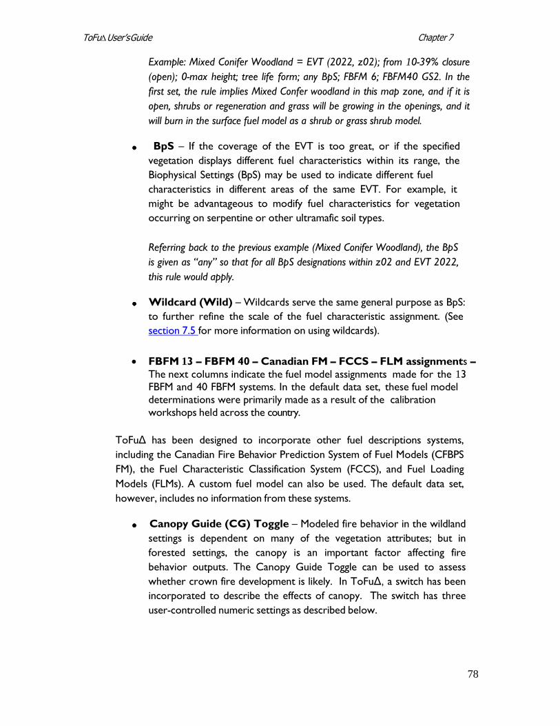
78
Chapter 7 ToFu∆ User’s Guide
Example: Mixed Conifer Woodland = EVT (2022, z02); from 10-39% closure
(open); 0-max height; tree life form; any BpS; FBFM 6; FBFM40 GS2. In the
first set, the rule implies Mixed Confer woodland in this map zone, and if it is
open, shrubs or regeneration and grass will be growing in the openings, and it
will burn in the surface fuel model as a shrub or grass shrub model.
BpS – If the coverage of the EVT is too great, or if the specified
vegetation displays different fuel characteristics within its range, the
Biophysical Settings (BpS) may be used to indicate different fuel
characteristics in different areas of the same EVT. For example, it
might be advantageous to modify fuel characteristics for vegetation
occurring on serpentine or other ultramafic soil types.
Referring back to the previous example (Mixed Conifer Woodland), the BpS
is given as “any” so that for all BpS designations within z02 and EVT 2022,
this rule would apply.
Wildcard (Wild) – Wildcards serve the same general purpose as BpS:
to further refine the scale of the fuel characteristic assignment. (See
section 7.5 for more information on using wildcards).
FBFM 13 – FBFM 40 – Canadian FM – FCCS – FLM assignments –
The next columns indicate the fuel model assignments made for the 13 FBFM and 40 FBFM systems. In the default data set, these fuel model
determinations were primarily made as a result of the calibration
workshops held across the country.
ToFuΔ has been designed to incorporate other fuel descriptions systems,
including the Canadian Fire Behavior Prediction System of Fuel Models (CFBPS
FM), the Fuel Characteristic Classification System (FCCS), and Fuel Loading
Models (FLMs). A custom fuel model can also be used. The default data set,
however, includes no information from these systems.
Canopy Guide (CG) Toggle – Modeled fire behavior in the wildland
settings is dependent on many of the vegetation attributes; but in
forested settings, the canopy is an important factor affecting fire
behavior outputs. The Canopy Guide Toggle can be used to assess
whether crown fire development is likely. In ToFuΔ, a switch has been
incorporated to describe the effects of canopy. The switch has three
user-controlled numeric settings as described below.
79
Chapter 7 ToFu∆ User’s Guide
o 0 = no canopy on the site.
o 1 = canopy base height (CBH) and canopy bulk density (CBD)
calculations from LANDFIRE data sets are used to indicate the
likelihood of crown fire on the site. This setting is used on a
forested site (dominated by “tree” life form) where torching and
crowning in the upper strata vegetation is common during times of
fire activity.
o 2 = used on forested sites (“tree” life form) where torching and
crowning will not occur but where the stand attributes will be used
in the calculations of surface fire behavior characteristics. (The
reason for keeping the canopy attributes in place is to adjust wind
speeds, shading, and sheltering for surface fire calculations).
Canopy Cover (CC) and Canopy Height (CH) – can be user-
designated by individual rule set while in editing mode. The default data
set uses LANDFIRE cover and height as portrayed in the range of cover
and height columns.
CBH 13 and CBH 40 – The user can specify CBH for a given Fuel
Rule by individual rule set for either of the surface fuel model grids they
will be producing (see section 6.3 for more information). Default
values are derived from the standard deviation plot data approach
(Martin, Napoli, and Smail, personal communication).
CBD 13 and CBD 40 – The user can specify CBD for a given Fuel
Rule by individual rule set for either of the surface fuel model grids they
will be producing (see section 6.3 for more information). Default
values are taken from the General Linear Model (GLM).
On/Off – A rule can be turned “On” or “Off” using a toggle switch. If
a rule is turned off without accounting for the area in another rule, the
total acres and percent coverage of the EVT may become out of
balance (less than or greater than 100%). If a rule is turned “Off,” the
user can still view relevant notes about its history or past use.
Acres and Percent of EVT – shows how many acres and percent of
the EVT a specific rule covers. When out of balance (over or under
100%), the Ruleset sheet tabs will indicate the problem (see section
7.6.3).
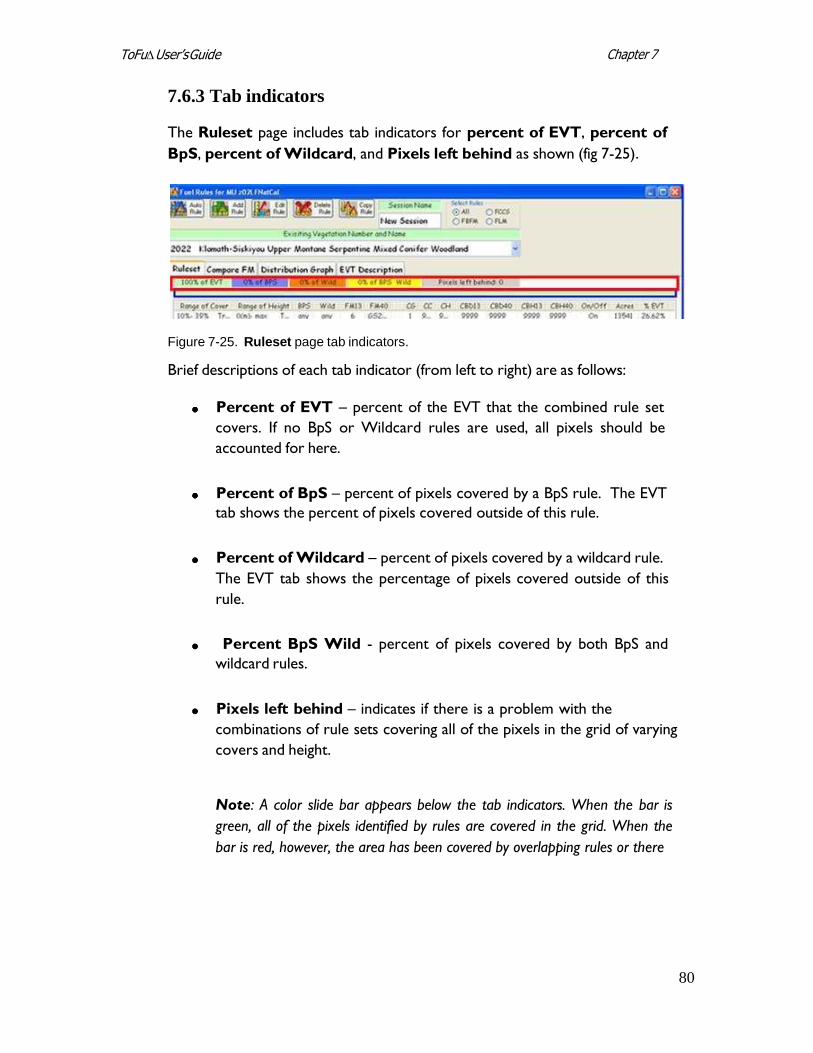
80
Chapter 7 ToFu∆ User’s Guide
7.6.3 Tab indicators
The Ruleset page includes tab indicators for percent of EVT, percent of
BpS, percent of Wildcard, and Pixels left behind as shown (fig 7-25).
Figure 7-25. Ruleset page tab indicators.
Brief descriptions of each tab indicator (from left to right) are as follows:
Percent of EVT – percent of the EVT that the combined rule set
covers. If no BpS or Wildcard rules are used, all pixels should be
accounted for here.
Percent of BpS – percent of pixels covered by a BpS rule. The EVT
tab shows the percent of pixels covered outside of this rule.
Percent of Wildcard – percent of pixels covered by a wildcard rule.
The EVT tab shows the percentage of pixels covered outside of this
rule.
Percent BpS Wild - percent of pixels covered by both BpS and
wildcard rules.
Pixels left behind – indicates if there is a problem with the
combinations of rule sets covering all of the pixels in the grid of varying
covers and height.
Note: A color slide bar appears below the tab indicators. When the bar is
green, all of the pixels identified by rules are covered in the grid. When the
bar is red, however, the area has been covered by overlapping rules or there
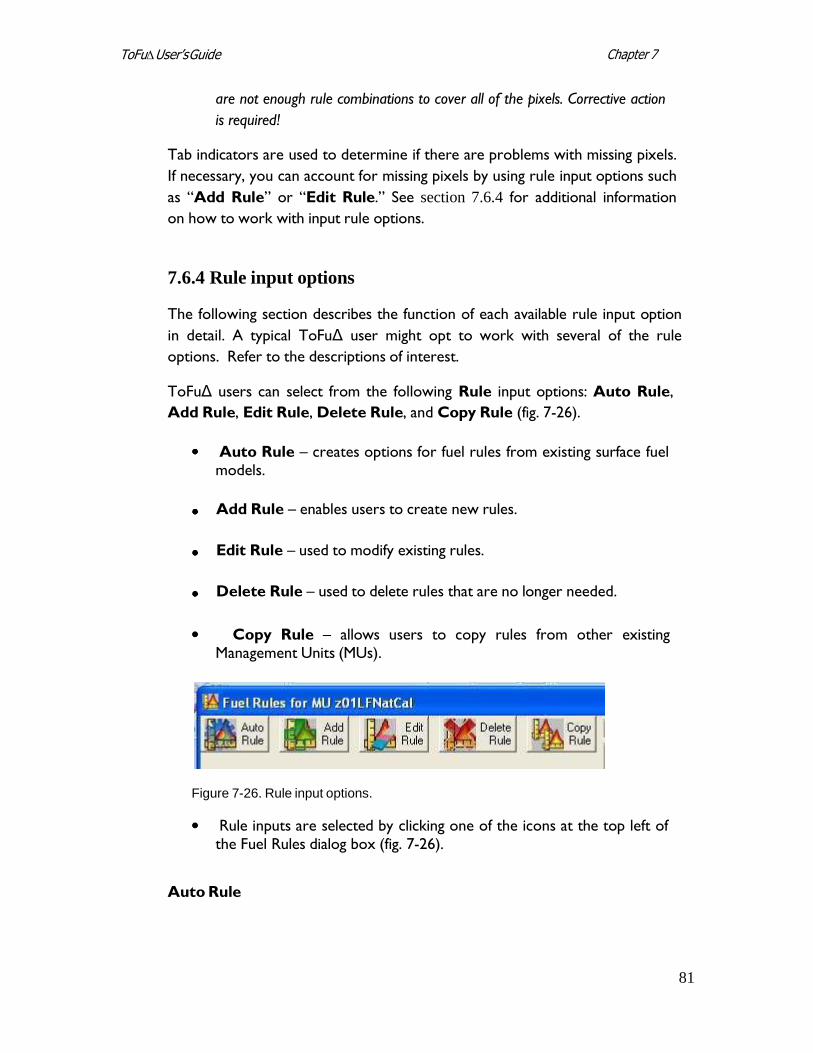
81
Chapter 7 ToFu∆ User’s Guide
are not enough rule combinations to cover all of the pixels. Corrective action
is required!
Tab indicators are used to determine if there are problems with missing pixels.
If necessary, you can account for missing pixels by using rule input options such
as “Add Rule” or “Edit Rule.” See section 7.6.4 for additional information
on how to work with input rule options.
7.6.4 Rule input options
The following section describes the function of each available rule input option
in detail. A typical ToFuΔ user might opt to work with several of the rule
options. Refer to the descriptions of interest.
ToFuΔ users can select from the following Rule input options: Auto Rule,
Add Rule, Edit Rule, Delete Rule, and Copy Rule (fig. 7-26).
Auto Rule – creates options for fuel rules from existing surface fuel models.
Add Rule – enables users to create new rules.
Edit Rule – used to modify existing rules.
Delete Rule – used to delete rules that are no longer needed.
Copy Rule – allows users to copy rules from other existing
Management Units (MUs).
Figure 7-26. Rule input options.
Rule inputs are selected by clicking one of the icons at the top left of the Fuel Rules dialog box (fig. 7-26).
Auto Rule
82
Chapter 7 ToFu∆ User’s Guide
Auto Rule is used with surface fuel model grids incorporated into the wildcard
slot. This function automatically builds rule sets and assigns surface fuel
models to other extents of the MU.
The Auto Rule icon creates options for fuel rules from existing surface fuel
model layers. For this option to work, the surface fuel model layer must be
included when creating the Management Unit, and it must include an FBFM
option.
Add Rule
The Add Rule option can be used when there are no available rules to edit.
The Add Rule option may be appropriate if rules exist and EVTs have been
added but EVTs are populated by “9999,” indicating “no data,” or when rule
sets are split out into new cover and height rules and there are no existing
applicable rules to edit.
For example, suppose a user had an existing rule specifying canopy cover of 10
to 49%, canopy height of 0-max, 9/TL6, and wanted to use a shrub model to
depict the more open condition with smaller trees. The user could add a rule
to state: canopy cover of 10 to 29%, canopy height of 0 to 25, 2/GS2, 10-29%,
25 – max, 9/TL6, and edit the existing rule to 30-49%, 0 – max, 9/TL6.
To use the Add Rule option, click the Add Rule icon (fig. 7-26).
The Add and Edit Rules dialog box opens as shown (fig. 7-27).
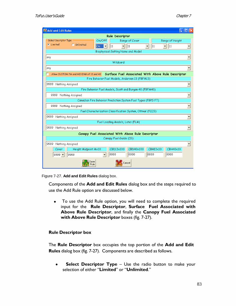
83
Chapter 7 ToFu∆ User’s Guide
Figure 7-27. Add and Edit Rules dialog box.
Components of the Add and Edit Rules dialog box and the steps required to
use the Add Rule option are discussed below.
To use the Add Rule option, you will need to complete the required
input for the Rule Descriptor, Surface Fuel Associated with
Above Rule Descriptor, and finally the Canopy Fuel Associated with Above Rule Descriptor boxes (fig. 7-27).
Rule Descriptor box
The Rule Descriptor box occupies the top portion of the Add and Edit
Rules dialog box (fig. 7-27). Components are described as follows.
Select Descriptor Type – Use the radio button to make your
selection of either “Limited” or “Unlimited.”
84
Chapter 7 ToFu∆ User’s Guide
Note: Using the “Limited” Descriptor Type option keeps the user from
creating illogical combinations that the data do not support. The
“Unlimited” option gives the user all combinations of cover and height in all
life forms whether they exist in the data or not.
Use the drop-down menu to toggle the Rule “On” or “Off.”
Use the drop-down menus to select a Range of Cover and Range of
Height.
Specify the Biophysical Setting Name and Model using the drop-
down menu. (Refer to section 3.1.1 for additional information on BpSs.)
A Wildcard option can be selected from the associated drop-down
menu. (Refer to section 7.5 for more information on wildcards.)
Surface Fuel Associated with Above Rule Descriptor box
Use the “Surface Fuel Associated with Above Rule Descriptor” section
in the middle of the Add and Edit Rules dialog box to make the following
selections.
Use drop-down menus to make assignments for Fire Behavior Fuel Models (13 and/or 40; FBFM13 and FBFM40), the Canadian Fire Behavior Prediction System Fuel Models (FBPS FM), Fuel Characteristic Classification System (FCCS) and Fuel Loading Models (FLM).
Canopy Fuel Associated With Above Rule Descriptor box
This section of the dialog box is used to make canopy selections as described
below.
Make a Canopy Fuel Guide (CG) selection using the drop-down box.
Modify CBD and CBH to express different fire behavior in different
conditions if desired.
Tip: When working with Add Rule, you must specify a Canopy Fuel
Guide (CG). If you do not, you will get a “9999” (“no value”).
85
Chapter 7 ToFu∆ User’s Guide
Save rule by clicking on the Save Rule icon at the lower left.
Close the Add and Edit Rules dialog box when you are finished. (It
does not close automatically).
Edit Rule
Use the Edit Rule selection when rules exist but modifications are desired,
such as when there is a need to adjust canopy cover or canopy height.
Tip: Be aware that you may need to use Add Rule to cover any pixels
missing if the whole range in the grid is not covered by the existing rule.
Example: A rule set for the Cottonwood Bosque EVT has the range of cover and
height worked out in logical fashion for the EVT, but you know that under dry
conditions, crowning is likely in this vegetation type. Currently, the rule set has 8/TL3
and a canopy guide (CG) of 2, which will use just canopy to adjust shading and wind
reduction. In this situation, to help model crowning, highlight the rule set for 20-54%
0-max height. Use the drop-down box for FBFM13 to select FM10, hit the drop-
down arrow for FBFM40 to select TL8-188, and use the drop-down menu for
Canopy Fuel Guide (CG) to select “1.” Save your edits by clicking on the Save
Rule icon. Subsequently, the Bosque rule sets will be 10-19%, 0-max, 5/GS2; 20-
59%, 0-max, 8/TL3.
To use the Edit Rule option, click the Edit Rule icon on the Fuel Rules dialog box (fig. 7-26).
The Add and Edit Rules dialog box opens (fig. 7-27). Components of the
Add and Edit Rule dialog box are the same as those described for the Add Rule
option. They are repeated here for convenience. Components of the Add
and Edit Rules dialog box and the steps required to use the Edit Rule option,
are discussed below.
To use the Edit Rule option, you will need to complete the required input for the Rule Descriptor, Surface Fuel Associated with Above Rule Descriptor, and finally the Canopy Fuel Associated with Above Rule Descriptor boxes (fig. 7-27).
Rule Selector Box
86
Chapter 7 ToFu∆ User’s Guide
The Rule Descriptor box occupies the top portion of the Add and Edit
Rules dialog box (fig. 7-27). Components are described as follows.
Select Descriptor Type – Use the radio button to make your
selection of either “Limited” or “Unlimited.”
Note: Using the “Limited” Descriptor Type option keeps the user from
creating illogical combinations that the data do not support. The
“Unlimited” option gives the user all combinations of cover and height in all
life forms whether they exist in the data or not.
Use the drop-down menu to toggle the Rule “On” or “Off.”
Use the drop-down menus to select a Range of Cover and Range of
Height.
Specify the Biophysical Setting Name and Model using the drop-
down menu. (Refer to section 3.1.1 for additional information on
BpSs).
A Wildcard option can be selected from the associated drop-down
menu. (See section 7.5 for more information on using the wildcard option).
Surface Fuel Associated with Above Rule Descriptor Box
Use the “Surface Fuel Associated with Above Rule Descriptor” section
in the middle of the Add and Edit Rules dialog box to make the following
selections.
Use drop-down menus to make assignments for Fire Behavior Fuel Models (13 and/or 40) (FBFM13 and FBFM40), the Canadian Fire Behavior Prediction System Fuel Models (FBPS FM), Fuel Characterization Classification System (FCCS) and Fuel Loading Models (FLM).
Canopy Fuel Associated With Above Rule Descriptor box
This section of the dialog box is used to make canopy selections as described
below.
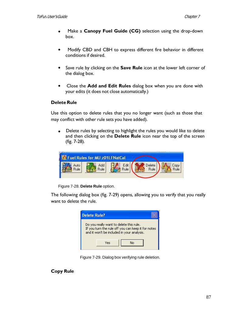
87
Chapter 7 ToFu∆ User’s Guide
Make a Canopy Fuel Guide (CG) selection using the drop-down
box.
Modify CBD and CBH to express different fire behavior in different
conditions if desired.
Save rule by clicking on the Save Rule icon at the lower left corner of
the dialog box.
Close the Add and Edit Rules dialog box when you are done with
your edits (it does not close automatically.)
Delete Rule
Use this option to delete rules that you no longer want (such as those that
may conflict with other rule sets you have added).
Delete rules by selecting to highlight the rules you would like to delete and then clicking on the Delete Rule icon near the top of the screen (fig. 7-28).
Figure 7-28. Delete Rule option.
The following dialog box (fig. 7-29) opens, allowing you to verify that you really
want to delete the rule.
Figure 7-29. Dialog box verifying rule deletion.
Copy Rule
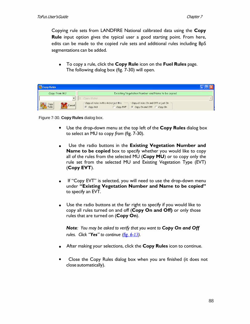
88
Chapter 7 ToFu∆ User’s Guide
Copying rule sets from LANDFIRE National calibrated data using the Copy
Rule input option gives the typical user a good starting point. From here,
edits can be made to the copied rule sets and additional rules including BpS
segmentations can be added.
To copy a rule, click the Copy Rule icon on the Fuel Rules page.
The following dialog box (fig. 7-30) will open.
Figure 7-30. Copy Rules dialog box.
Use the drop-down menu at the top left of the Copy Rules dialog box to select an MU to copy from (fig. 7-30).
Use the radio buttons in the Existing Vegetation Number and
Name to be copied box to specify whether you would like to copy all of the rules from the selected MU (Copy MU) or to copy only the rule set from the selected MU and Existing Vegetation Type (EVT) (Copy EVT).
If “Copy EVT” is selected, you will need to use the drop-down menu
under “Existing Vegetation Number and Name to be copied” to specify an EVT.
Use the radio buttons at the far right to specify if you would like to
copy all rules turned on and off (Copy On and Off) or only those rules that are turned on (Copy On).
Note: You may be asked to verify that you want to Copy On and Off
rules. Click “Yes” to continue (fig. 6-13).
After making your selections, click the Copy Rules icon to continue.
Close the Copy Rules dialog box when you are finished (it does not
close automatically).
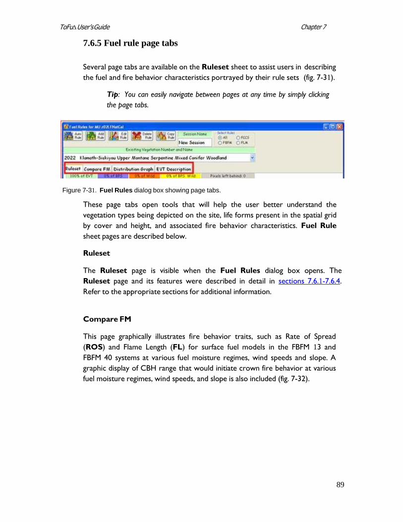
89
Chapter 7 ToFu∆ User’s Guide
7.6.5 Fuel rule page tabs
Several page tabs are available on the Ruleset sheet to assist users in describing
the fuel and fire behavior characteristics portrayed by their rule sets (fig. 7-31).
Tip: You can easily navigate between pages at any time by simply clicking
the page tabs.
Figure 7-31. Fuel Rules dialog box showing page tabs.
These page tabs open tools that will help the user better understand the
vegetation types being depicted on the site, life forms present in the spatial grid
by cover and height, and associated fire behavior characteristics. Fuel Rule
sheet pages are described below.
Ruleset
The Ruleset page is visible when the Fuel Rules dialog box opens. The
Ruleset page and its features were described in detail in sections 7.6.1-7.6.4.
Refer to the appropriate sections for additional information.
Compare FM
This page graphically illustrates fire behavior traits, such as Rate of Spread
(ROS) and Flame Length (FL) for surface fuel models in the FBFM 13 and
FBFM 40 systems at various fuel moisture regimes, wind speeds and slope. A
graphic display of CBH range that would initiate crown fire behavior at various
fuel moisture regimes, wind speeds, and slope is also included (fig. 7-32).
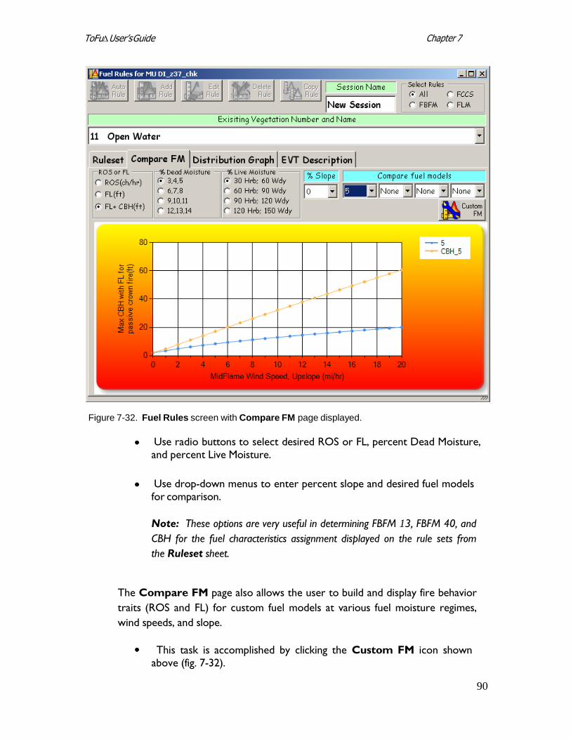
90
Chapter 7 ToFu∆ User’s Guide
Figure 7-32. Fuel Rules screen with Compare FM page displayed.
Use radio buttons to select desired ROS or FL, percent Dead Moisture, and percent Live Moisture.
Use drop-down menus to enter percent slope and desired fuel models
for comparison.
Note: These options are very useful in determining FBFM 13, FBFM 40, and
CBH for the fuel characteristics assignment displayed on the rule sets from
the Ruleset sheet.
The Compare FM page also allows the user to build and display fire behavior
traits (ROS and FL) for custom fuel models at various fuel moisture regimes,
wind speeds, and slope.
This task is accomplished by clicking the Custom FM icon shown above (fig. 7-32).
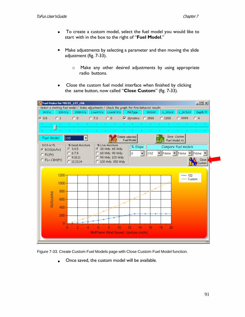
91
Chapter 7 ToFu∆ User’s Guide
To create a custom model, select the fuel model you would like to
start with in the box to the right of “Fuel Model.”
Make adjustments by selecting a parameter and then moving the slide
adjustment (fig. 7-33).
o Make any other desired adjustments by using appropriate radio buttons.
Close the custom fuel model interface when finished by clicking the same button, now called “Close Custom” (fig. 7-33).
Figure 7-33. Create Custom Fuel Models page with Close Custom Fuel Model function.
Once saved, the custom model will be available.
92
Chapter 7 ToFu∆ User’s Guide
Distribution Graph
The Distribution Graph tab opens a graph that shows the distribution of
acres of classified cover and height by life form that exist in the grid data for
the entire EVT or by BpS or Wildcard (if a wildcard is used in the MU grid) (fig.
7-34).
You can use the Distribution Graph page (fig. 7-34) to view the height of the
vegetation by cover and the numbers of acres present in the selected EVT
within the defined MU.
The x-axis shows 10% breaks of cover by life form; the y-axis corresponds to
the number of acres within the EVT in the MU’s extent.
The legend displays the line indications by height corresponding to the percent
cover and represents the number of acres.
To work with the Distribution Graph:
Click on the Distribution Graph tab.
Use the relevant drop-down menus to display the distribution of an
EVT, BpS, or wildcard.
Note: If the graph is in the “T” category, tree cover is represented; if “S” then
shrub cover is represented; and if H, it is made up of herbaceous cover.
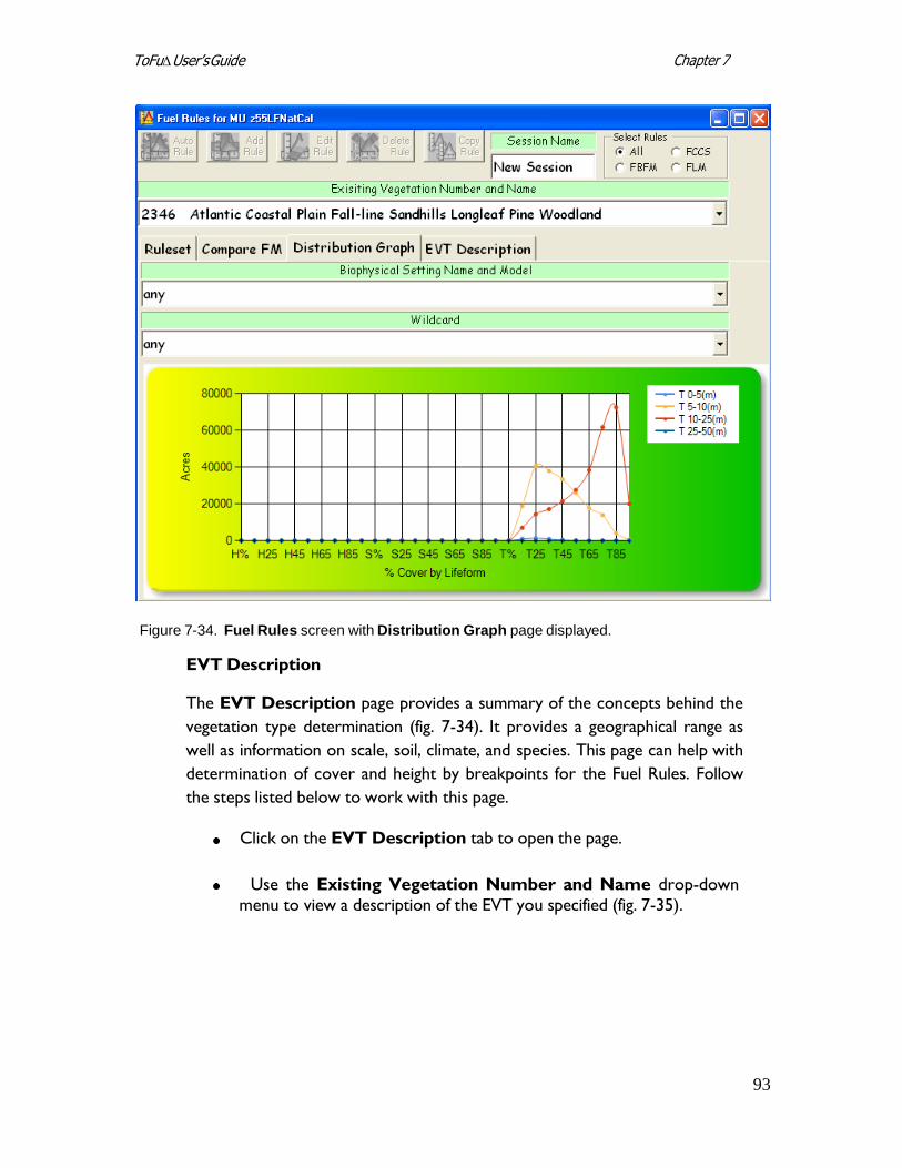
93
Chapter 7 ToFu∆ User’s Guide
Figure 7-34. Fuel Rules screen with Distribution Graph page displayed.
EVT Description
The EVT Description page provides a summary of the concepts behind the
vegetation type determination (fig. 7-34). It provides a geographical range as
well as information on scale, soil, climate, and species. This page can help with
determination of cover and height by breakpoints for the Fuel Rules. Follow
the steps listed below to work with this page.
Click on the EVT Description tab to open the page.
Use the Existing Vegetation Number and Name drop-down
menu to view a description of the EVT you specified (fig. 7-35).
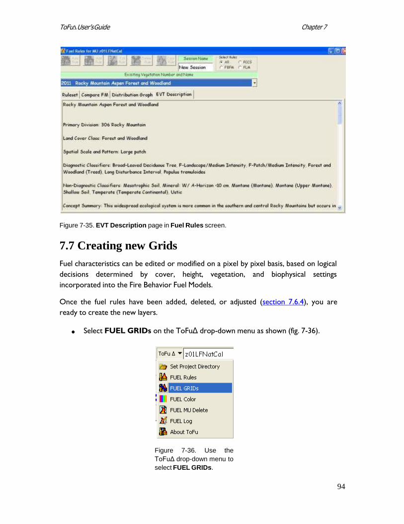
94
Chapter 7 ToFu∆ User’s Guide
Figure 7-35. EVT Description page in Fuel Rules screen.
7.7 Creating new Grids
Fuel characteristics can be edited or modified on a pixel by pixel basis, based on logical
decisions determined by cover, height, vegetation, and biophysical settings
incorporated into the Fire Behavior Fuel Models.
Once the fuel rules have been added, deleted, or adjusted (section 7.6.4), you are
ready to create the new layers.
Select FUEL GRIDs on the ToFuΔ drop-down menu as shown (fig. 7-36).
Figure 7-36. Use the
ToFuΔ drop-down menu to
select FUEL GRIDs.
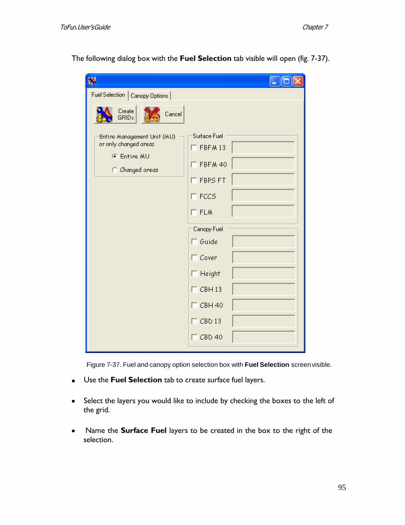
95
Chapter 7 ToFu∆ User’s Guide
The following dialog box with the Fuel Selection tab visible will open (fig. 7-37).
Figure 7-37. Fuel and canopy option selection box with Fuel Selection screen visible.
Use the Fuel Selection tab to create surface fuel layers.
Select the layers you would like to include by checking the boxes to the left of
the grid.
Name the Surface Fuel layers to be created in the box to the right of the
selection.
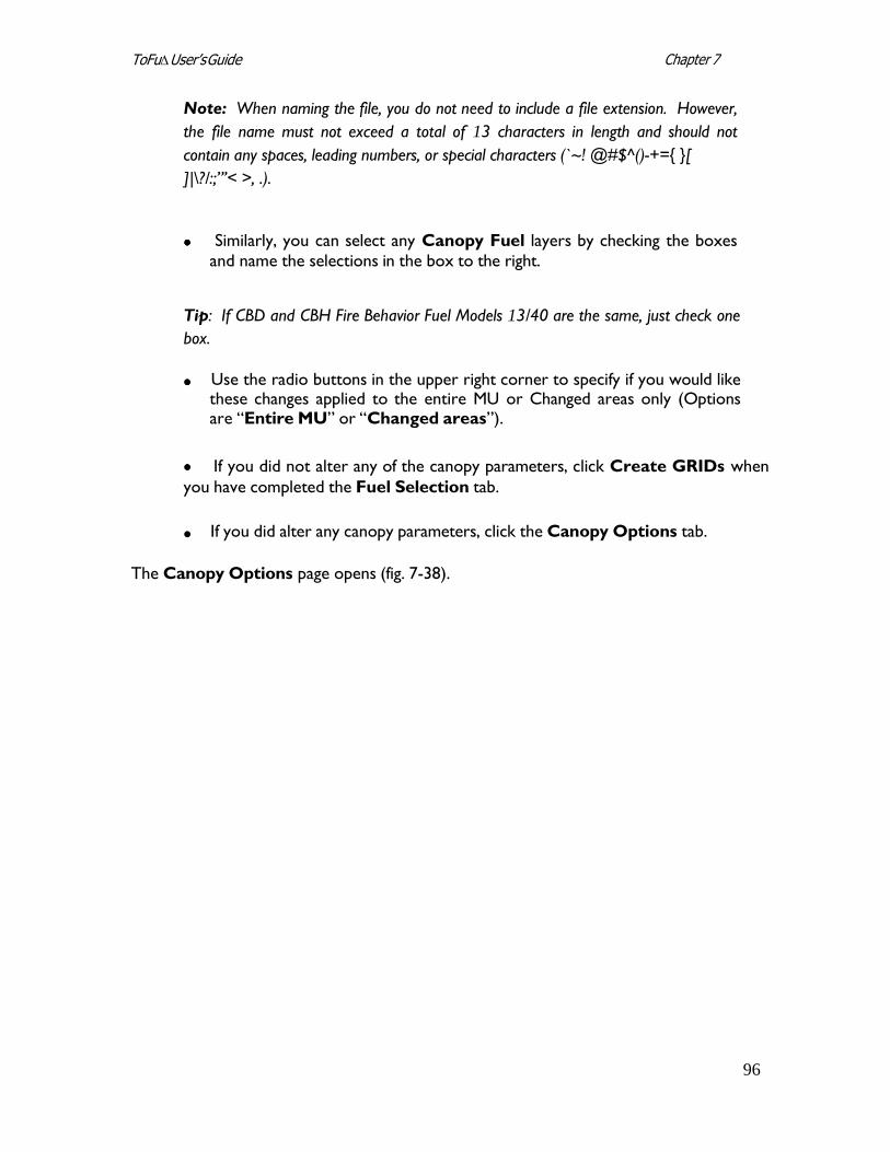
96
Chapter 7 ToFu∆ User’s Guide
Note: When naming the file, you do not need to include a file extension. However,
the file name must not exceed a total of 13 characters in length and should not
contain any spaces, leading numbers, or special characters (`~! @#$^()-+={ }[
]|\?/:;”’< >, .).
Similarly, you can select any Canopy Fuel layers by checking the boxes
and name the selections in the box to the right.
Tip: If CBD and CBH Fire Behavior Fuel Models 13/40 are the same, just check one
box.
Use the radio buttons in the upper right corner to specify if you would like these changes applied to the entire MU or Changed areas only (Options are “Entire MU” or “Changed areas”).
If you did not alter any of the canopy parameters, click Create GRIDs when
you have completed the Fuel Selection tab.
If you did alter any canopy parameters, click the Canopy Options tab.
The Canopy Options page opens (fig. 7-38).
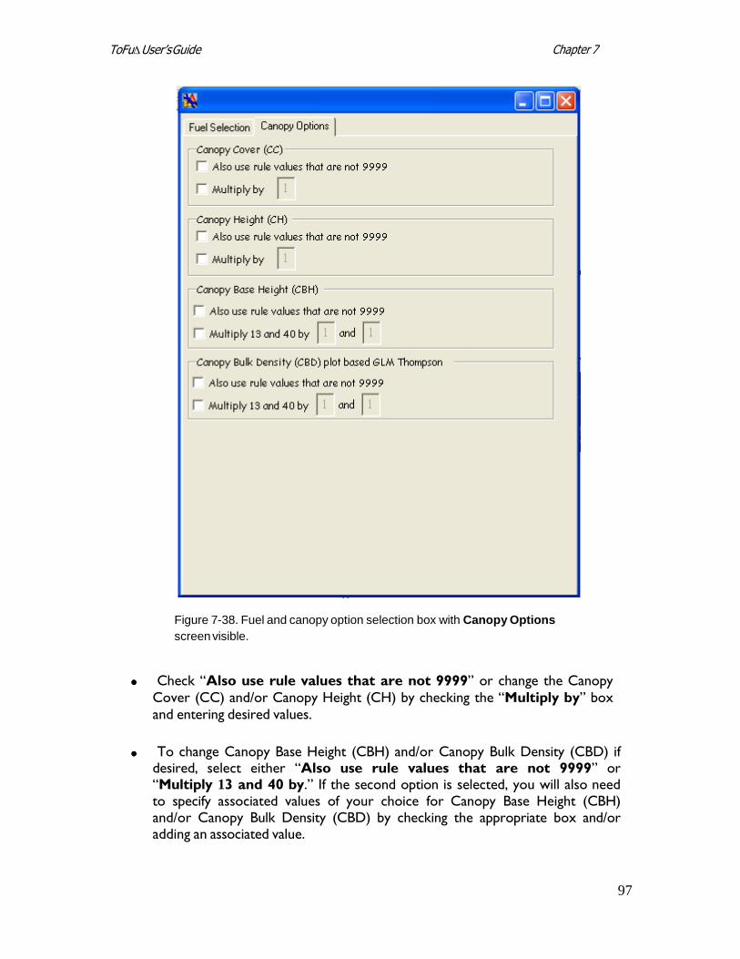
97
Chapter 7 ToFu∆ User’s Guide
Figure 7-38. Fuel and canopy option selection box with Canopy Options
screen visible.
Check “Also use rule values that are not 9999” or change the Canopy
Cover (CC) and/or Canopy Height (CH) by checking the “Multiply by” box
and entering desired values.
To change Canopy Base Height (CBH) and/or Canopy Bulk Density (CBD) if
desired, select either “Also use rule values that are not 9999” or “Multiply 13 and 40 by.” If the second option is selected, you will also need to specify associated values of your choice for Canopy Base Height (CBH) and/or Canopy Bulk Density (CBD) by checking the appropriate box and/or adding an associated value.
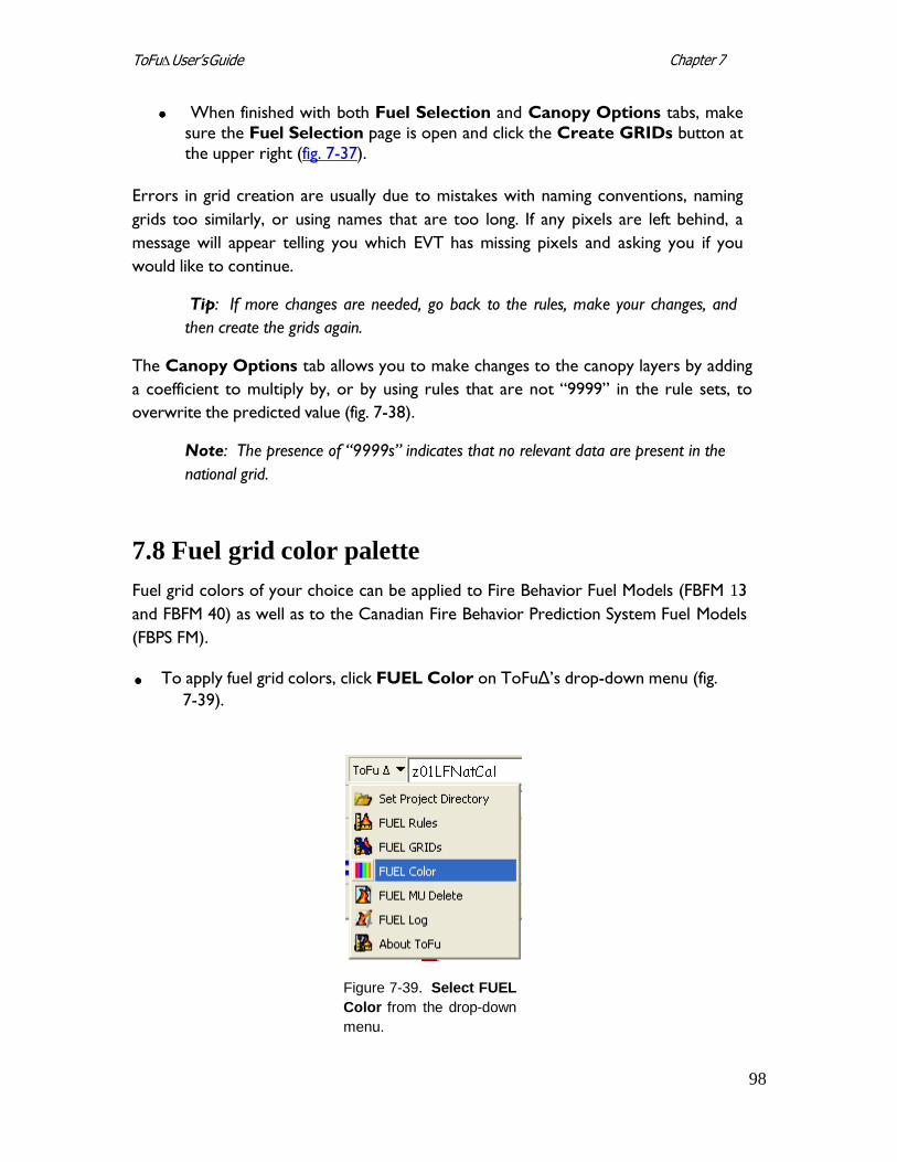
98
Chapter 7 ToFu∆ User’s Guide
When finished with both Fuel Selection and Canopy Options tabs, make
sure the Fuel Selection page is open and click the Create GRIDs button at
the upper right (fig. 7-37).
Errors in grid creation are usually due to mistakes with naming conventions, naming
grids too similarly, or using names that are too long. If any pixels are left behind, a
message will appear telling you which EVT has missing pixels and asking you if you
would like to continue.
Tip: If more changes are needed, go back to the rules, make your changes, and
then create the grids again.
The Canopy Options tab allows you to make changes to the canopy layers by adding
a coefficient to multiply by, or by using rules that are not “9999” in the rule sets, to
overwrite the predicted value (fig. 7-38).
Note: The presence of “9999s” indicates that no relevant data are present in the
national grid.
7.8 Fuel grid color palette
Fuel grid colors of your choice can be applied to Fire Behavior Fuel Models (FBFM 13
and FBFM 40) as well as to the Canadian Fire Behavior Prediction System Fuel Models
(FBPS FM).
To apply fuel grid colors, click FUEL Color on ToFuΔ’s drop-down menu (fig.
7-39).
Figure 7-39. Select FUEL
Color from the drop-down
menu.
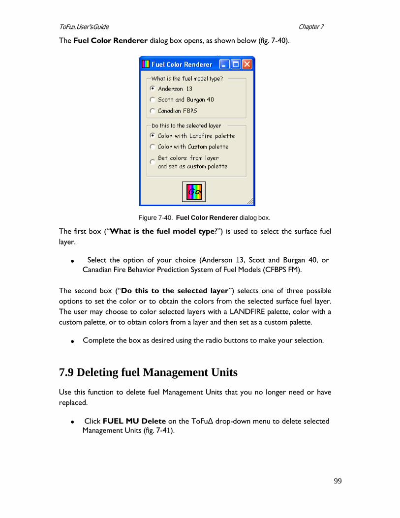
99
Chapter 7 ToFu∆ User’s Guide
The Fuel Color Renderer dialog box opens, as shown below (fig. 7-40).
Figure 7-40. Fuel Color Renderer dialog box.
The first box (“What is the fuel model type?”) is used to select the surface fuel
layer.
Select the option of your choice (Anderson 13, Scott and Burgan 40, or
Canadian Fire Behavior Prediction System of Fuel Models (CFBPS FM).
The second box (“Do this to the selected layer”) selects one of three possible
options to set the color or to obtain the colors from the selected surface fuel layer.
The user may choose to color selected layers with a LANDFIRE palette, color with a
custom palette, or to obtain colors from a layer and then set as a custom palette.
Complete the box as desired using the radio buttons to make your selection.
7.9 Deleting fuel Management Units
Use this function to delete fuel Management Units that you no longer need or have
replaced.
Click FUEL MU Delete on the ToFuΔ drop-down menu to delete selected
Management Units (fig. 7-41).
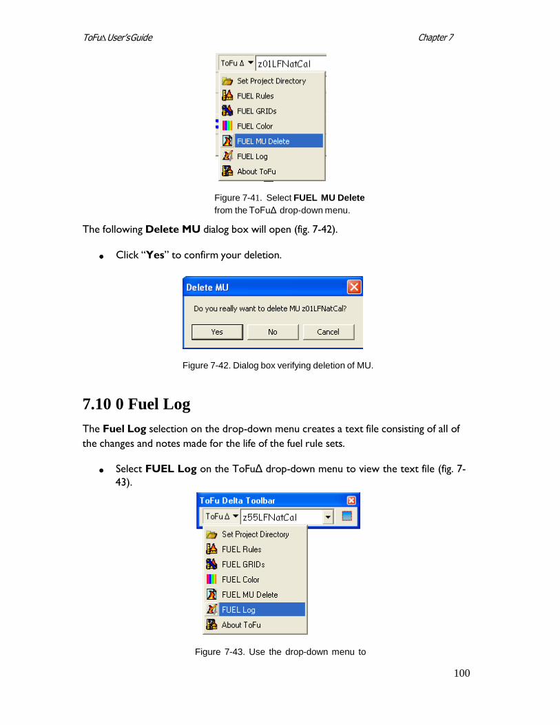
Chapter 7 ToFu∆ User’s Guide
100
Figure 7-41. Select FUEL MU Delete
from the ToFuΔ drop-down menu.
The following Delete MU dialog box will open (fig. 7-42).
Click “Yes” to confirm your deletion.
Figure 7-42. Dialog box verifying deletion of MU.
7.10 0 Fuel Log
The Fuel Log selection on the drop-down menu creates a text file consisting of all of
the changes and notes made for the life of the fuel rule sets.
Select FUEL Log on the ToFuΔ drop-down menu to view the text file (fig. 7-
43).
Figure 7-43. Use the drop-down menu to
Chapter 7 ToFu∆ User’s Guide
101
open the FUEL log file.
7.11 About ToFuΔ
Clicking on About ToFuΔ in the drop-down menu displays the following screen (fig.
7-44), which includes information on version number and tool development.
Figure 7-44. About ToFuΔ screen.
7.12 Help
The help button provides information about the program. Click on the icon to open
the Help Utility.
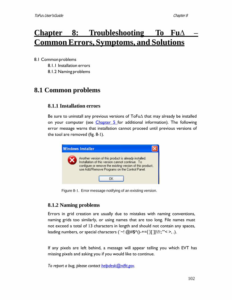
102
Chapter 8 ToFu∆ User’s Guide
Chapter 8: Troubleshooting To Fu∆ –
Common Errors, Symptoms, and Solutions
8.1 Common problems
8.1.1 Installation errors
8.1.2 Naming problems
8.1 Common problems
8.1.1 Installation errors
Be sure to uninstall any previous versions of ToFu∆ that may already be installed
on your computer (see Chapter 5 for additional information). The following
error message warns that installation cannot proceed until previous versions of
the tool are removed (fig. 8-1).
Figure 8-1. Error message notifying of an existing version.
8.1.2 Naming problems
Errors in grid creation are usually due to mistakes with naming conventions,
naming grids too similarly, or using names that are too long. File names must
not exceed a total of 13 characters in length and should not contain any spaces,
leading numbers, or special characters (`~! @#$^()-+={ }[ ]|\?/:;”’< >, .).
If any pixels are left behind, a message will appear telling you which EVT has
missing pixels and asking you if you would like to continue.
To report a bug, please contact [email protected].
103
Appendix A ToFu∆ User’s Guide
Appendix A: References
Allen, T.F.H; Hoekstra, T.W. 1992. Toward a unified ecology. New York: Columbia
University Press. 384p.
Anderson, H. E. 1982. Aids to determining fuel models for estimating fire behavior.
Gen. Tech. Rep. INT-122. Ogden, UT: U.S. Department of Agriculture, Forest Service,
Intermountain Research Station. 22 p.
Brown, J.K.; Arno, S.F.; Barrett, S.W.; Menakis, J.P. 1994. Comparing the prescribed
natural fire program with presettlement fires in the Selway-Bitterroot Wilderness.
International Journal of Wildland Fire. 4:157-168.
Comer, P.J. and others 2003. Ecological Systems of the United States: a Working
Classification of U.S. Terrestrial Systems.
ESSA Technologies Ltd. 2005a. TELSA - Tool for Exploratory Landscape Scenario
Analyses Analyses: User’s Guide Version 3.3. Vancouver, BC: ESSA Technologies Ltd.
236 pp.
ESSA Technologies Ltd. 2005b. Vegetation dynamics development tool: User guide,
version 5.1. Vancouver, BC: ESSA Technologies Ltd. 196 pp.
Keane, R.E.; Holsinger, L.M.; Pratt, S.D. 2006. Simulating historical landscape dynamics
using the landscape fire succession model LANDSUM version 4.0. Gen. Tech. Rep.
RMRS-GTR-171CD. Fort Collins, CO: U.S. Department of Agriculture, Forest Service,
Rocky Mountain Research Station. 73 pp.
Lutes, D.C.; Keane, R.E.; Caratti, J.F. 2008. [In review] A surface fuel classification for
estimating fire effects. International Journal of Wildland Fire.
Martin, Napoli, and Smail. Personal communication. Stinger Ghaffarian Technologies, Inc.,
contractor to the U.S. Geological Survey (USGS) Earth Resources Observation and
Science (EROS) Center, Sioux Falls, SD. Work performed under contract G10PC00044.
NatureServe. http://www.natureserve.org/.
Ottmar, R.D.; Sandberg, D.V.; Riccardi, C.L.; Prichard, S.J. 2007. An Overview of the
Fuel Characteristic Classification System – Quantifying, Classifying, and Creating
Fuelbeds for Resource Planning. Canadian Journal of Forest Research. 37(12): 2383-
2393.
104
Appendix A ToFu∆ User’s Guide
Reeves, M.C.; Ryan, K.C.; Rollins, M.G.; Thompson, T.G. 2009. Spatial fuel data products
of the LANDFIRE Project. International Journal of Wildland Fire. 18: 250-267.
Scott, J. H.; Burgan, R. E. 2005. Standard fire behavior fuel models: a comprehensive set
for use with Rothermel’s surface fire spread model. Gen Tech. Rep. RMRS-GTR-153.
Fort Collins, CO: U.S. Department of Agriculture, Forest Service, Rocky Mountain
Research Station. 72 p.
Scott, J. H.; Reinhardt, E. D. 2001. Assessing crown fire potential by linking models of
surface and crown fire behavior. Res. Pap. RMRS-RP-29. Fort Collins, CO: U.S.
Department of Agriculture, Forest Service, Rocky Mountain Research Station. 59 p.
Toney, Chris. Stem mapping of plots canopy cover in LANDFIRE. (Unpublished).
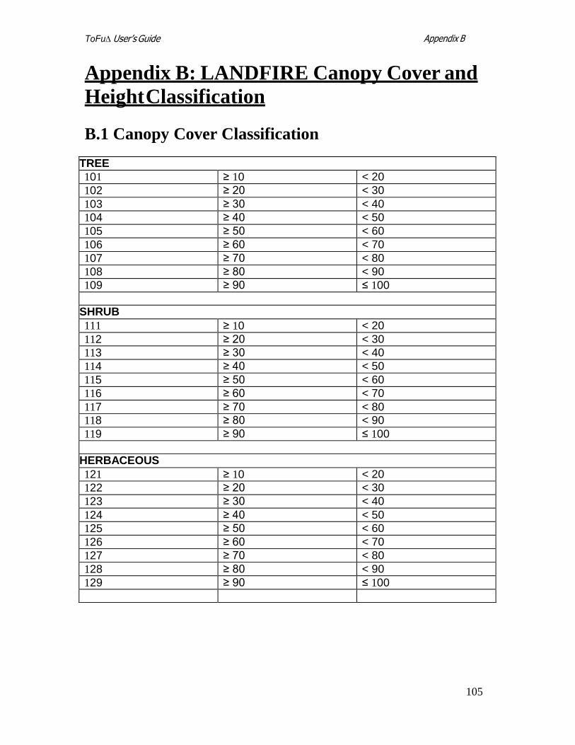
105
Appendix B ToFu∆ User’s Guide
Appendix B: LANDFIRE Canopy Cover and
Height Classification
B.1 Canopy Cover Classification
TREE
101 ≥ 10 < 20
102 ≥ 20 < 30
103 ≥ 30 < 40
104 ≥ 40 < 50
105 ≥ 50 < 60
106 ≥ 60 < 70
107 ≥ 70 < 80
108 ≥ 80 < 90
109 ≥ 90 ≤ 100
SHRUB
111 ≥ 10 < 20
112 ≥ 20 < 30
113 ≥ 30 < 40
114 ≥ 40 < 50
115 ≥ 50 < 60
116 ≥ 60 < 70
117 ≥ 70 < 80
118 ≥ 80 < 90
119 ≥ 90 ≤ 100
HERBACEOUS
121 ≥ 10 < 20
122 ≥ 20 < 30
123 ≥ 30 < 40
124 ≥ 40 < 50
125 ≥ 50 < 60
126 ≥ 60 < 70
127 ≥ 70 < 80
128 ≥ 80 < 90
129 ≥ 90 ≤ 100
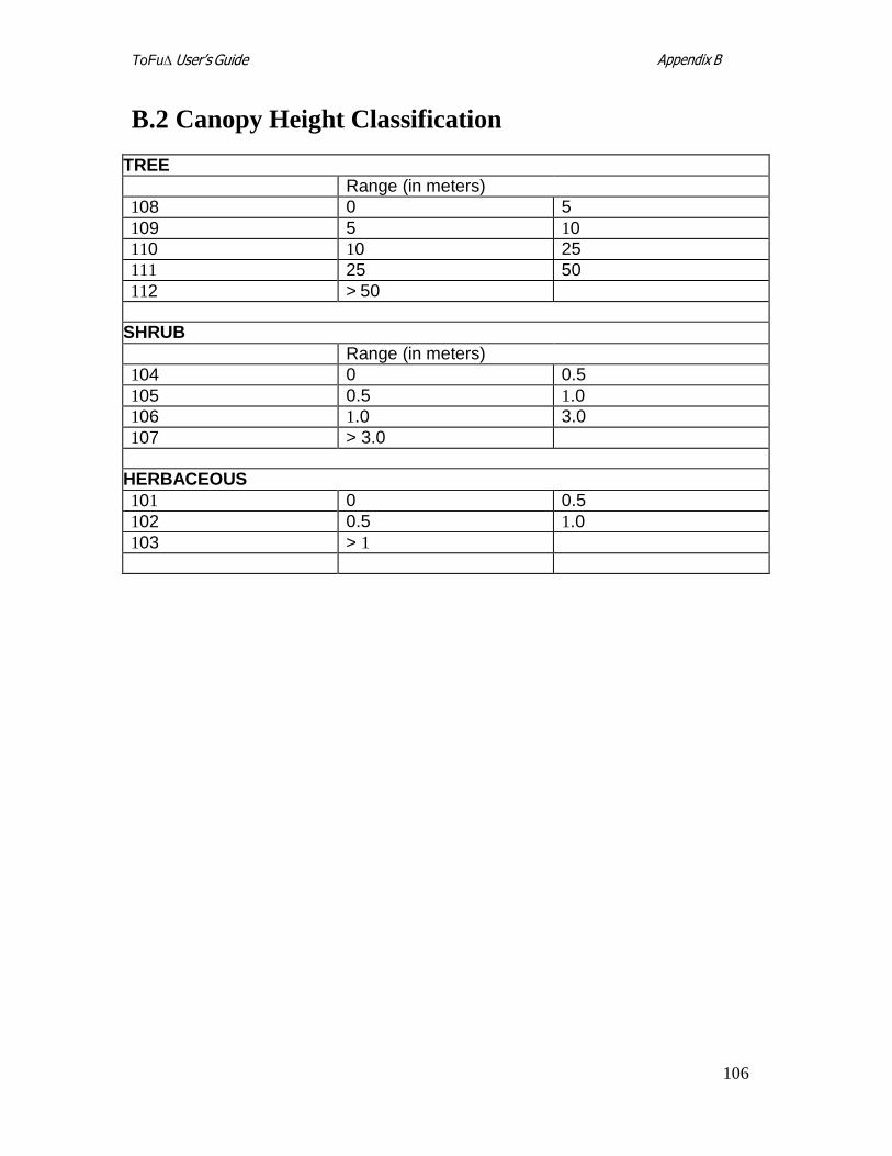
106
Appendix B ToFu∆ User’s Guide
B.2 Canopy Height Classification
TREE Range (in meters)
108 0 5
109 5 10
110 10 25
111 25 50
112 > 50
SHRUB
Range (in meters)
104 0 0.5
105 0.5 1.0
106 1.0 3.0
107 > 3.0
HERBACEOUS
101 0 0.5
102 0.5 1.0
103 > 1
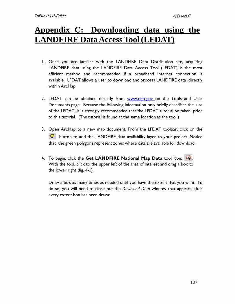
107
Appendix C ToFu∆ User’s Guide
Appendix C: Downloading data using the
LANDFIRE Data Access Tool (LFDAT)
1. Once you are familiar with the LANDFIRE Data Distribution site, acquiring
LANDFIRE data using the LANDFIRE Data Access Tool (LFDAT) is the most
efficient method and recommended if a broadband Internet connection is
available. LFDAT allows a user to download and process LANDFIRE data directly
within ArcMap.
2. LFDAT can be obtained directly from www.niftt.gov on the Tools and User
Documents page. Because the following information only briefly describes the use
of the LFDAT, it is strongly recommended that the LFDAT tutorial be taken prior
to this tutorial. (The tutorial is found at the same location as the tool.)
3. Open ArcMap to a new map document. From the LFDAT toolbar, click on the
button to add the LANDFIRE data availability layer to your project. Notice
that the green polygons represent zones where data are available for download.
4. To begin, click the Get LANDFIRE National Map Data tool icon: .
With the tool, click to the upper left of the area of interest and drag a box to
the lower right (fig. 4-1).
Draw a box as many times as needed until you have the extent that you want. To
do so, you will need to close out the Download Data window that appears after
every extent box has been drawn.
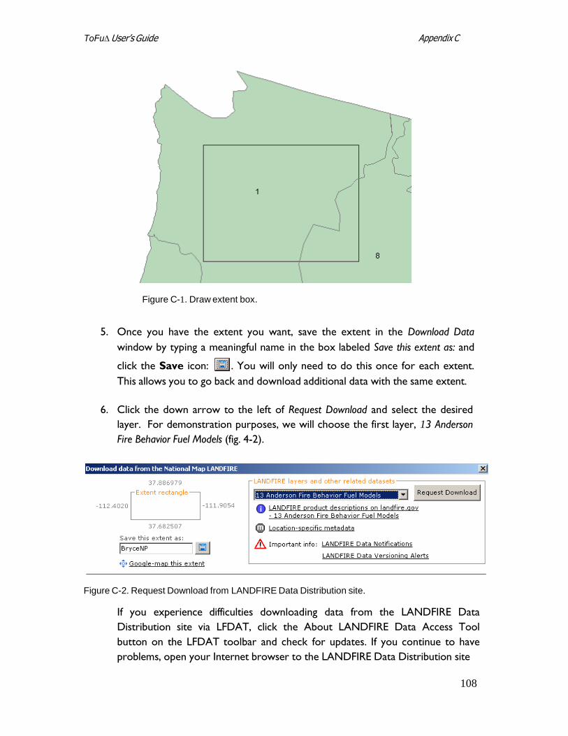
108
Appendix C ToFu∆ User’s Guide
Figure C-1. Draw extent box.
5. Once you have the extent you want, save the extent in the Download Data
window by typing a meaningful name in the box labeled Save this extent as: and
click the Save icon: . You will only need to do this once for each extent.
This allows you to go back and download additional data with the same extent.
6. Click the down arrow to the left of Request Download and select the desired
layer. For demonstration purposes, we will choose the first layer, 13 Anderson
Fire Behavior Fuel Models (fig. 4-2).
Figure C-2. Request Download from LANDFIRE Data Distribution site.
If you experience difficulties downloading data from the LANDFIRE Data
Distribution site via LFDAT, click the About LANDFIRE Data Access Tool
button on the LFDAT toolbar and check for updates. If you continue to have
problems, open your Internet browser to the LANDFIRE Data Distribution site
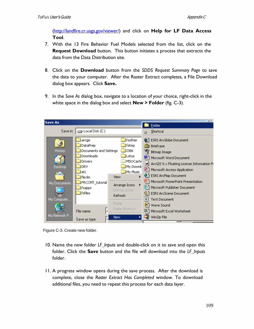
109
Appendix C ToFu∆ User’s Guide
(http://landfire.cr.usgs.gov/viewer/) and click on Help for LF Data Access
Tool.
7. With the 13 Fire Behavior Fuel Models selected from the list, click on the
Request Download button. This button initiates a process that extracts the
data from the Data Distribution site.
8. Click on the Download button from the SDDS Request Summary Page to save
the data to your computer. After the Raster Extract completes, a File Download
dialog box appears. Click Save.
9. In the Save As dialog box, navigate to a location of your choice, right-click in the
white space in the dialog box and select New > Folder (fig. C-3).
Figure C-3. Create new folder.
10. Name the new folder LF_Inputs and double-click on it to save and open this
folder. Click the Save button and the file will download into the LF_Inputs
folder.
11. A progress window opens during the save process. After the download is
complete, close the Raster Extract Has Completed window. To download
additional files, you need to repeat this process for each data layer.
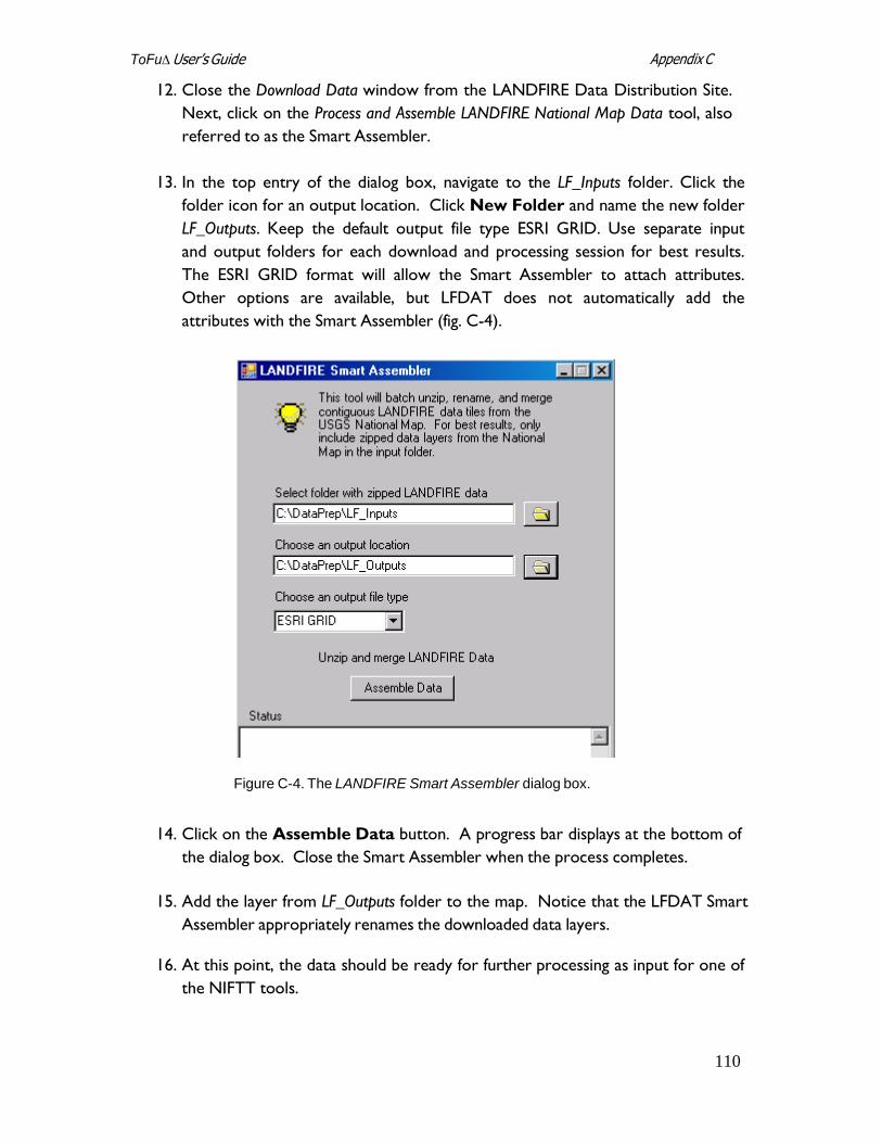
110
Appendix C ToFu∆ User’s Guide
12. Close the Download Data window from the LANDFIRE Data Distribution Site.
Next, click on the Process and Assemble LANDFIRE National Map Data tool, also
referred to as the Smart Assembler.
13. In the top entry of the dialog box, navigate to the LF_Inputs folder. Click the
folder icon for an output location. Click New Folder and name the new folder
LF_Outputs. Keep the default output file type ESRI GRID. Use separate input
and output folders for each download and processing session for best results.
The ESRI GRID format will allow the Smart Assembler to attach attributes.
Other options are available, but LFDAT does not automatically add the
attributes with the Smart Assembler (fig. C-4).
Figure C-4. The LANDFIRE Smart Assembler dialog box.
14. Click on the Assemble Data button. A progress bar displays at the bottom of
the dialog box. Close the Smart Assembler when the process completes.
15. Add the layer from LF_Outputs folder to the map. Notice that the LFDAT Smart
Assembler appropriately renames the downloaded data layers.
16. At this point, the data should be ready for further processing as input for one of
the NIFTT tools.