Embed Size (px)
Citation preview

Spencer 1 34th Annual Small Satellite Conference
SSC20-II-01
The LightSail 2 Controlled Solar Sailing Demonstration Mission
David A. Spencer, Justin R. Mansell Purdue University
701 W. Stadium Ave., West Lafayette, Indiana, 47907 [email protected], [email protected]
Bruce Betts
The Planetary Society 60 S. Los Robles Ave., Pasadena, California, 91101
John M. Bellardo California Polytechnic State University
1 Grand Ave., San Luis Obispo, California, 93407 [email protected]
Alex Diaz
Ecliptic Enterprises Corporation 398 W. Washington Blvd., Suite 100, Pasadena, California, 91103
Barbara Plante Boreal Space
3207 Bridle Drive, Suite 200, Hayward, California, 94541 [email protected]
ABSTRACT The LightSail 2 mission is the culmination of a decade-long program sponsored by The Planetary Society to advance solar sailing technology. The objective of LightSail 2 is to demonstrate controlled solar sailing in Earth orbit using a CubeSat platform. The LightSail 2 attitude is controlled using a single-axis momentum wheel and magnetic torque rods. During solar sailing operations, two 90 degree slews are performed each orbit to harness momentum from solar photons. Flight data show that LightSail 2 is successfully controlling its orientation relative to the Sun, and the controlled thrust from solar radiation pressure is measurably reducing the rate of orbital decay. The Planetary Society declared LightSail 2 mission success on July 31, 2019. This paper provides an overview of the LightSail 2 mission implementation, including the design of the flight system and flight software, and the pre-launch testing program. A summary of LightSail 2 mission operations is provided, including a description of the ground system. Solar sailing performance is presented, and anomalies encountered during the mission are discussed. The flight team continues to refine solar sailing performance and conduct on-orbit imaging for engineering purposes and to engage public interest. The LightSail program is entirely donor-funded, with over 50,000 contributors around the globe.
INTRODUCTION The Planetary Society initiated the LightSail program in June 2009 to advance solar sailing technology, as a pathfinder for future space science missions that are enabled by solar sail propulsion. Through the LightSail program, The Planetary Society also sought to engage the public and advance awareness of solar sailing, thereby increasing public support for space exploration.
The first attempted solar sailing mission was The Planetary Society’s Cosmos 1, however, the flight system did not reach orbit due to a launch vehicle failure.1 The NanoSail-D2 mission developed by NASA Marshall Space Flight Center (MSFC) and Ames Research Center (ARC) demonstrated the successful deployment of a 10 m2 sail from a three-unit (3U) CubeSat in January 2010.2 The Japanese Aerospace Exploration Agency (JAXA) mission Interplanetary Kite-craft Accelerated by Radiation Of
Spencer 2 34th Annual Small Satellite Conference
the Sun (IKAROS) successfully deployed a 196 m2 solar sail on June 10, 2010.3 By dynamically controlling the reflectivity of 80 liquid crystal panels at the outer edge of the sail, control of the rotation rate and orientation of the sail were successfully demonstrated during the six-month transfer to Venus.4,5 These flight projects, as well as solar sail ground test programs, provided a foundation for the solar sailing technology advancements pursued through the LightSail program.6
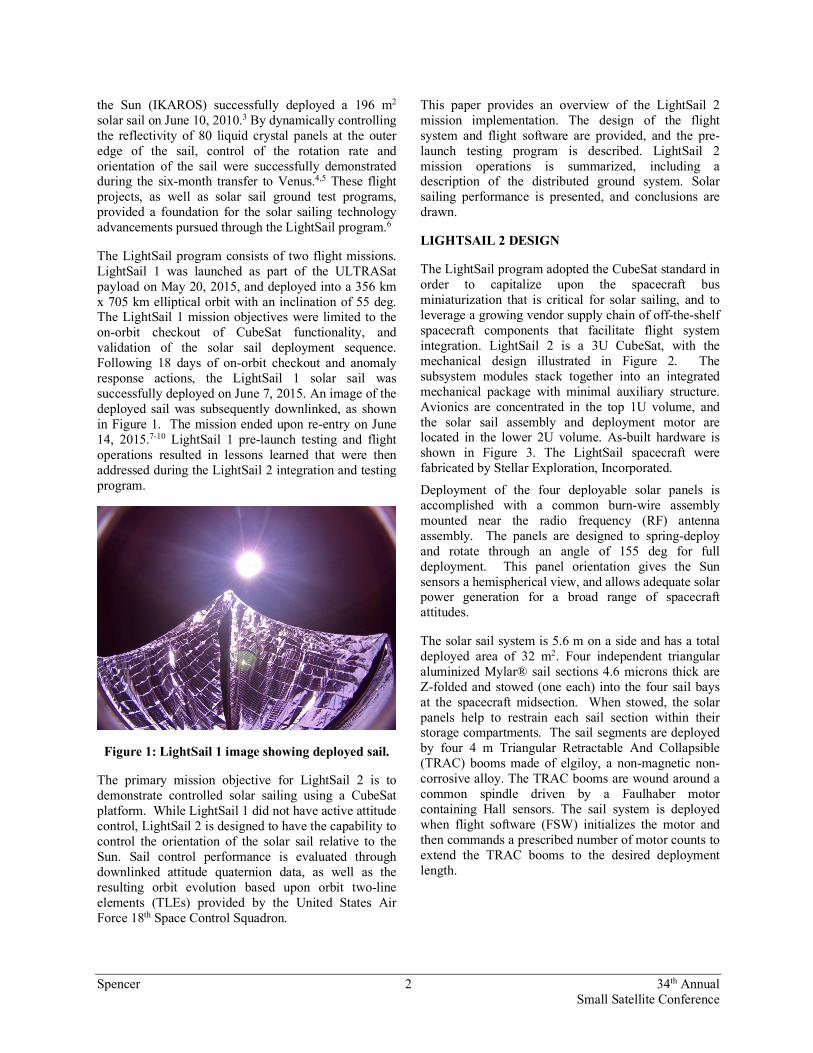
The LightSail program consists of two flight missions. LightSail 1 was launched as part of the ULTRASat payload on May 20, 2015, and deployed into a 356 km x 705 km elliptical orbit with an inclination of 55 deg. The LightSail 1 mission objectives were limited to the on-orbit checkout of CubeSat functionality, and validation of the solar sail deployment sequence. Following 18 days of on-orbit checkout and anomaly response actions, the LightSail 1 solar sail was successfully deployed on June 7, 2015. An image of the deployed sail was subsequently downlinked, as shown in Figure 1. The mission ended upon re-entry on June 14, 2015.7-10 LightSail 1 pre-launch testing and flight operations resulted in lessons learned that were then addressed during the LightSail 2 integration and testing program.
Figure 1: LightSail 1 image showing deployed sail.
The primary mission objective for LightSail 2 is to demonstrate controlled solar sailing using a CubeSat platform. While LightSail 1 did not have active attitude control, LightSail 2 is designed to have the capability to control the orientation of the solar sail relative to the Sun. Sail control performance is evaluated through downlinked attitude quaternion data, as well as the resulting orbit evolution based upon orbit two-line elements (TLEs) provided by the United States Air Force 18th Space Control Squadron.
This paper provides an overview of the LightSail 2 mission implementation. The design of the flight system and flight software are provided, and the pre-launch testing program is described. LightSail 2 mission operations is summarized, including a description of the distributed ground system. Solar sailing performance is presented, and conclusions are drawn.
LIGHTSAIL 2 DESIGN
The LightSail program adopted the CubeSat standard in order to capitalize upon the spacecraft bus miniaturization that is critical for solar sailing, and to leverage a growing vendor supply chain of off-the-shelf spacecraft components that facilitate flight system integration. LightSail 2 is a 3U CubeSat, with the mechanical design illustrated in Figure 2. The subsystem modules stack together into an integrated mechanical package with minimal auxiliary structure. Avionics are concentrated in the top 1U volume, and the solar sail assembly and deployment motor are located in the lower 2U volume. As-built hardware is shown in Figure 3. The LightSail spacecraft were fabricated by Stellar Exploration, Incorporated.
Deployment of the four deployable solar panels is accomplished with a common burn-wire assembly mounted near the radio frequency (RF) antenna assembly. The panels are designed to spring-deploy and rotate through an angle of 155 deg for full deployment. This panel orientation gives the Sun sensors a hemispherical view, and allows adequate solar power generation for a broad range of spacecraft attitudes.
The solar sail system is 5.6 m on a side and has a total deployed area of 32 m2. Four independent triangular aluminized Mylar® sail sections 4.6 microns thick are Z-folded and stowed (one each) into the four sail bays at the spacecraft midsection. When stowed, the solar panels help to restrain each sail section within their storage compartments. The sail segments are deployed by four 4 m Triangular Retractable And Collapsible (TRAC) booms made of elgiloy, a non-magnetic non-corrosive alloy. The TRAC booms are wound around a common spindle driven by a Faulhaber motor containing Hall sensors. The sail system is deployed when flight software (FSW) initializes the motor and then commands a prescribed number of motor counts to extend the TRAC booms to the desired deployment length.

Spencer 3 34th Annual Small Satellite Conference
Figure 2: Exploded view of LightSail 2 CubeSat configuration.
Figure 3: LightSail flight hardware, inspected by flight system engineer Alex Diaz.
The electrical power subsystem is composed of the solar arrays, batteries, power distribution, and fault protection circuitry. A 5.6 Ah battery pack coupled with a solar panel system produces an average power of 8.5 W. In full Sun, the four deployed solar panels generate
a maximum 6 W of power each with the body-mounted -Z panel providing 2 W. Solar power is routed through the main avionics board and charges a set of 8 lithium-polymer batteries providing power during eclipse periods. Each battery cell has its own charge monitoring/protection circuit and ties individually to the spacecraft bus. Each cell monitor independently provides overvoltage and undervoltage protection as well as overcurrent and short-circuit protection to that cell.
The main avionics board contains a low state-of-charge recovery system that initiates when the bus voltage drops below the specified limit. Power analyses were conducted for each planned mission mode. Depth of discharge values were analyzed for all modes, with a worst-case depth-of-discharge of 15% during the sail deployment sequence. Temperature sensors are installed on all solar panels, in both cameras, and in the primary avionics board.
Three magnetotorquers, one in each body axis, provide coarse attitude control using the Earth’s magnetic field. A Sinclair Interplanetary momentum wheel facilitates more rapid slews about the spacecraft Y-axis.
Two Planetary Society Cameras (PSCAMs) developed by the Aerospace Corporation are mounted at the tips of opposing solar panels. The 2-megapixel 185 deg fish-eye color cameras are inward-looking when the panels are in their stowed positions and outward-looking when deployed. As images are taken, each 1600 x 1200 JPEG image is stored in camera memory along with a 120 x 90 pixel thumbnail. Each camera has a heater installed in series with a thermostat initially set to turn on if the camera temperature falls below 0°C. Flight software turns off the camera if the operating temperature rises above 70°C.
The use of thermal blankets and ambient heat from electronics provides a stable thermal environment for all electronics within the spacecraft. Hot and cold cases were evaluated in a thermal model using the Thermal Desktop software for the planned orbit, evaluated over a range of orbit ascending node locations. Scenarios corresponding to the stowed configuration (prior to solar panel deployment) and the deployed configuration (solar panels and solar sail deployed) were evaluated. Avionics board temperatures are contained in the telemetry beacon, and are routinely downlinked.
The primary avionics board for LightSail 2 is a Tyvak Intrepid computer board (version 8), which is Atmel-based and hosts a Linux operating system. Integrated onto a daughterboard is an AX5042 UHF radio transceiver with an operating frequency of 437.025

Spencer 4 34th Annual Small Satellite Conference
MHz for both uplink and downlink. Sun sensors are mounted at the tips of each deployable solar panel and on the -Z panel, magnetometers are located near the tips of the each deployable panel, and gyros measuring three-axis angular rates are located in the avionics bay.
LightSail flight software and firmware are written in the C programming language, and are functionally partitioned between the Intrepid board and the payload interface board (PIB). A Linux-based operating system hosted on the Intrepid board features libraries, (e.g., event handling, command handling) and kernel space drivers (e.g. SPI, I2C, RTC) that facilitate FSW development. Table 1 lists application-level control processes that are supported by user space drivers built and integrated into the Intrepid architecture. Table 2 lists functions performed by the PIB.
The ADCS software was designed in MATLAB/Simulink and autogenerated to C code and integrated with the flight software. Attitude control software and interfaces to ADCS sensors and actuators are allocated to the Intrepid board. ADCS runs a 1 Hz control loop that first initializes required peripheral devices. It then checks for ground commands and performs functions including modification of the ADCS control loop rate, sensor data collection, and execution of the ADCS control law including torque rod and momentum wheel actuation. During sail deployment, LightSail 2 ceases active attitude control and commands the Microchip Payload Interface Card (PIC) to deploy the sail. The PIC actively commutates and controls the brushless DC deployment motor.
LightSail 2 has the capability to receive and process ADCS and payload flight software updates in flight. Spacecraft commands are parameterized to maximize flexibility during testing and mission operations. Telemetry is downlinked via 227-byte beacon packets. Mission elapsed time, command counter, power, thermal, ADCS and deployment data are included in the beacon data to provide assessments of on-orbit performance during the mission. Beacon packets are downlinked at a nominal 7-second cadence and are supplemented by spacecraft logs that further characterize spacecraft behavior.
Flight software development activities are facilitated by BenchSat test platform, shown in Figure 4. BenchSat consists of most of the hardware components of the LightSail 2 spacecraft avionics, including the Intrepid board, PIB, cameras, radio, magnetometers, sun sensors, gyros and solar panels. For subsystem components that are lacking, simulators have been incorporated. For example, BenchSat lacks the actual solar sail deployment motor/spindle, but a clutch
mechanism was introduced to simulate the load experienced by the deployment motor. It also does not have actual torque rods, but instead has torque rod simulators in the form of 30 Ω resistors (27 Ω is the nominal torque rod impedance at steady state). In addition to its role in flight software development, BenchSat was used to perform component testing prior to integration into flight units, served as a ground station during communications testing, was used for testing operational procedures during Operations Readiness Testing (ORTs), and is used for verification of on-orbit procedures during mission operations.
Figure 4: BenchSat is used as a test platform for LightSail 2.
Table 1: Intrepid board flight software control processes
Process Functionality
acs_process Implements ADCS algorithms
payload_process Communicates with and commands the PIC to deploy the solar sail and collect telemetry.
beacon_process Packages collected telemetry for downlink to ground station.
camera_process Camera monitoring, commanding and telemetry, take images during deployment and move to processor board memory.
sys_manager Collects and monitors the telemetry from most of the spacecraft sensors. Implements software battery charge protection.
satcomm Sends and receives commands over the radio.
device drivers Interfaces with all devices, including SPI, i2c, GPIO, gyro, magnetometers, sun sensors, and magnatorquers.
Table 2: Payload Interface Board control processes
Process Functionality
main Hardware and software initialization, communicates with the Intrepid board, and controls motor deployment
spiWrapper, I2CWrapper
Wrappers for Microchip drivers

Spencer 5 34th Annual Small Satellite Conference
PRE-LAUNCH TESTING The LightSail 2 pre-launch testing program was used for verification and validation (V&V) of project requirements, and to establish flight team readiness for operations. Tests were performed at the subsystem level, and system-level day-in-the-life (DITL) testing was completed with full flight team participation. Operations Readiness Tests (ORTs) were conducted to train the flight team and exercise the flight procedures prior to launch. Ecliptic Enterprises Corporation was the implementing organization for the pre-launch testing program.
Two DITL tests were performed during the LightSail 2 integration and testing phase. DITL testing allowed full sensor checkouts, deployments of the RF antenna, solar panels, and solar sail, and imaging operations. DITL testing was performed using spacecraft power, with commanding and telemetry data return via RF link to the California Polytechnic State University, San Luis Obispo (Cal Poly) tracking station. DITL testing aided in refining the flight command procedures, undergoing several iterations during the test campaign.
The pre-sail deployment phase of the DITL test was performed in a clean room at Cal Poly. It began with a simulated Poly-Picosatellite Orbital Deployer (P-POD) deployment by removing the power inhibit switches and turning on the avionics subsystem. Antenna deployment, radio squelching timers, camera operations, and solar panel deployments were then all commanded in a flight like manner either through automated software routings or via ground commands. System health checks were performed by analyzing spacecraft telemetry. When the pre-sail deployment phase of DITL test was complete, the spacecraft was powered down and packaged in preparation for the sail deployment phase.
Due to the physical space required for a solar sail deployment, the LightSail 2 spacecraft was transported to the larger testing space in the Bonderson facility at Cal Poly. The spacecraft was set up in the center of a large deployment test table. When all the operators were ready, the spacecraft was once again powered on and solar sail deployment was completed.
At the end of DITL testing, procedures were executed to post-process data, take physical measurements of the sail hardware, then stow the solar sail and deployment booms. Spacecraft hardware and software was then reset to a ready-for-flight state.
DITL testing was instrumental in improving the concept of operations, and resulted in software changes to address test anomalies. As an example, during a
DITL test it was observed that the spacecraft was unable to receive commands during operation of the deployment motor. This finding led to the incorporation of a software deployment timeout to safeguard against a scenario in which the full deployment motor count could not be met despite continuous motor activation.
Due to the importance of proper ADCS performance for meeting the LightSail 2 mission objectives, additional ADCS phasing tests and sensor calibrations were performed at the Space Dynamics Laboratory at Utah State University (USU) and at the University of California Los Angeles (UCLA). At both test facilities, the spacecraft was placed in a Helmholtz cage to establish a specified magnetic field, allowing magnetometer calibration. Two of the four solar-panel mounted magnetometers were found to be faulty, and were rendered passive in the ADCS software. At USU, a two degree-of-freedom platform allowed characterization of the torque rod and momentum wheel phasing under ADCS control. The maximum dipole for each torque rod was validated, and a polarity error for the momentum wheel was found and fixed in flight software. The solar angle and gyro sensors were tested and found to be performing nominally.
During the LightSail development phase, the team collaborated to define Operational Readiness Tests (ORTs) that consisted of mission scenarios to be executed once the spacecraft was on-orbit. These scenarios included initial spacecraft detumble, attaining a stable pointing attitude, sail deployment, and solar sailing. ORTs were performed at various points during the test program and were run using the Benchsat test platform. ORTs were performed with the full LightSail 2 flight team using the flight procedures, with commanding of BenchSat via the Cal Poly ground station. The ORTs resulted in a flight team that was proficient in terms of operating the LightSail 2 spacecraft.
Flight system bakeout and thermal cycle testing were performed at Cal Poly prior to shipment to the Air Force Research Laboratory (AFRL) in Albuquerque, New Mexico. LightSail 2 was integrated into the flight Poly Picosat Orbital Deployer (P-POD), hosted by the Georgia Institute of Technology Prox-1 satellite.11-13 The Prox-1/LightSail 2 integrated system was then environmentally tested at AFRL. For each spacecraft axis, a low-level sine sweep was performed before and after vibration testing of the system. A sine burst test was performed, followed by another low-level sine sweep. Upon completion of vibration testing, LightSail 2 was removed from the P-POD, and a functional test
Spencer 6 34th Annual Small Satellite Conference
was performed. The battery was fully charged, and the spacecraft was reintegrated into the P-POD for launch.
MISSION OPERATIONS
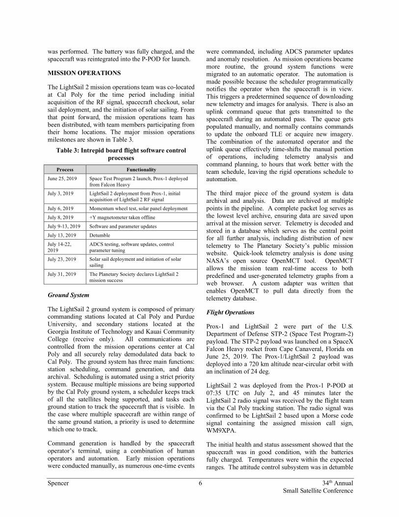
The LightSail 2 mission operations team was co-located at Cal Poly for the time period including initial acquisition of the RF signal, spacecraft checkout, solar sail deployment, and the initiation of solar sailing. From that point forward, the mission operations team has been distributed, with team members participating from their home locations. The major mission operations milestones are shown in Table 3.
Table 3: Intrepid board flight software control processes
Process Functionality
June 25, 2019 Space Test Program 2 launch, Prox-1 deployed from Falcon Heavy
July 3, 2019 LightSail 2 deployment from Prox-1, initial acquisition of LightSail 2 RF signal
July 6, 2019 Momentum wheel test, solar panel deployment
July 8, 2019 +Y magnetometer taken offline
July 9-13, 2019 Software and parameter updates
July 13, 2019 Detumble
July 14-22, 2019
ADCS testing, software updates, control parameter tuning
July 23, 2019 Solar sail deployment and initiation of solar sailing
July 31, 2019 The Planetary Society declares LightSail 2 mission success
Ground System
The LightSail 2 ground system is composed of primary commanding stations located at Cal Poly and Purdue University, and secondary stations located at the Georgia Institute of Technology and Kauai Community College (receive only). All communications are controlled from the mission operations center at Cal Poly and all securely relay demodulated data back to Cal Poly. The ground system has three main functions: station scheduling, command generation, and data archival. Scheduling is automated using a strict priority system. Because multiple missions are being supported by the Cal Poly ground system, a scheduler keeps track of all the satellites being supported, and tasks each ground station to track the spacecraft that is visible. In the case where multiple spacecraft are within range of the same ground station, a priority is used to determine which one to track.
Command generation is handled by the spacecraft operator’s terminal, using a combination of human operators and automation. Early mission operations were conducted manually, as numerous one-time events
were commanded, including ADCS parameter updates and anomaly resolution. As mission operations became more routine, the ground system functions were migrated to an automatic operator. The automation is made possible because the scheduler programmatically notifies the operator when the spacecraft is in view. This triggers a predetermined sequence of downloading new telemetry and images for analysis. There is also an uplink command queue that gets transmitted to the spacecraft during an automated pass. The queue gets populated manually, and normally contains commands to update the onboard TLE or acquire new imagery. The combination of the automated operator and the uplink queue effectively time-shifts the manual portion of operations, including telemetry analysis and command planning, to hours that work better with the team schedule, leaving the rigid operations schedule to automation.
The third major piece of the ground system is data archival and analysis. Data are archived at multiple points in the pipeline. A complete packet log serves as the lowest level archive, ensuring data are saved upon arrival at the mission server. Telemetry is decoded and stored in a database which serves as the central point for all further analysis, including distribution of new telemetry to The Planetary Society’s public mission website. Quick-look telemetry analysis is done using NASA’s open source OpenMCT tool. OpenMCT allows the mission team real-time access to both predefined and user-generated telemetry graphs from a web browser. A custom adapter was written that enables OpenMCT to pull data directly from the telemetry database.
Flight Operations
Prox-1 and LightSail 2 were part of the U.S. Department of Defense STP-2 (Space Test Program-2) payload. The STP-2 payload was launched on a SpaceX Falcon Heavy rocket from Cape Canaveral, Florida on June 25, 2019. The Prox-1/LightSail 2 payload was deployed into a 720 km altitude near-circular orbit with an inclination of 24 deg.
LightSail 2 was deployed from the Prox-1 P-POD at 07:35 UTC on July 2, and 45 minutes later the LightSail 2 radio signal was received by the flight team via the Cal Poly tracking station. The radio signal was confirmed to be LightSail 2 based upon a Morse code signal containing the assigned mission call sign, WM9XPA.
The initial health and status assessment showed that the spacecraft was in good condition, with the batteries fully charged. Temperatures were within the expected ranges. The attitude control subsystem was in detumble
Spencer 7 34th Annual Small Satellite Conference
mode, and angular rates were low (< 2 deg/s). The flight team established two-way communications with the spacecraft and began working through checkout activities per the flight procedure. The recurring autonomous antenna deployment process was disabled, and a file listing was downlinked. The error in the spacecraft clock was determined, and an updated TLE orbit state was uplinked to the spacecraft. The spacecraft clock was then updated, which resulted in an expected spacecraft reboot. Detailed attitude determination and control system (ADCS) information was downlinked for assessment. Test images were acquired from each of the two cameras mounted on the solar panels. The attitude control mode was changed from Mode 0 (detumble) to Mode 1 (Z-axis alignment). Mode 1 aligns the longitudinal axis of the CubeSat with the Earth’s magnetic field vector, which is a favorable attitude for communications. A functional checkout of the momentum wheel was successfully performed. The script-driven activity commanded the momentum wheel to speeds of 500 and 2000 rpm in each direction, followed by commanded torques of +/- 0.001 Nm. The flight team then proceeded with solar panel deployment, and acquired additional test images from the panel-mounted cameras. The next two weeks were spent testing and updating the ADCS software to validate the pointing control capability that would be needed for solar sailing.
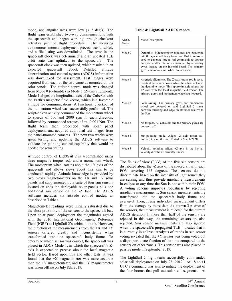
Attitude control of LightSail 2 is accomplished using three magnetic torque rods and a momentum wheel. The momentum wheel rotates about the +Y axis of the spacecraft and allows slews about this axis to be conducted rapidly. Attitude knowledge is provided by two 3-axis magnetometers on the +X and +Y solar panels and supplemented by a suite of four sun sensors located on ends the deployable solar panels plus one additional sun sensor on the -Z face. The ADCS software includes six attitude control modes, as described in Table 4.
Magnetometer readings were initially saturated due to the close proximity of the sensors to the spacecraft bus. Upon solar panel deployment the magnitudes agreed with the 2010 International Geomagnetic Reference Field (IGRF) at LightSail 2’s orbital altitude. However, the direction of the measurements from the +X and +Y sensors differed greatly and inconsistently when transformed into the spacecraft body frame. To determine which sensor was correct, the spacecraft was placed in ADCS Mode 1, in which the spacecraft’s Z-axis is expected to precess about the local magnetic field vector. Based upon this and other tests, it was found that the +X magnetometer was more accurate than the +Y magnetometer, and the +Y magnetometer was taken offline on July 8th, 2019.
Table 4: LightSail 2 ADCS modes.
ADCS Mode
Mode Description
Mode 0 Detumble. Magnetometer readings are converted into the spacecraft body frame and B-dot control is used to generate torque rod commands to oppose the spacecraft’s rotation as measured by secondary gyros located on the Intrepid board. The primary gyros and momentum wheel are not used.
Mode 1 Magnetic alignment. The Z-axis torque rod is set to constant maximum power while the others act as in the detumble mode. This approximately aligns the +Z axis with the local magnetic field vector. The primary gyros and momentum wheel are not used.
Mode 2 Solar sailing. The primary gyros and momentum wheel are powered on and LightSail 2 slews between thrusting and edge-on attitudes relative to the Sun
Mode 3 No torques. All actuators and the primary gyros are powered off.
Mode 4 Sun-pointing mode. Aligns -Z axis (solar sail normal) toward the Sun. Tested in March 2020.
Mode 5 Velocity pointing. Aligns +Z axis in the inertial velocity direction. Currently unused.
The fields of view (FOV) of the five sun sensors are distributed about the -Z axis of the spacecraft with each FOV covering 165 degrees. The sensors do not discriminate based on the intensity of light source they are sensing and thus provide unreliable measurements in eclipse or any time the Sun is not within their FOV. A voting scheme improves robustness by rejecting unreliable measurements. Sun sensor measurements are transformed into the spacecraft body frame and averaged. Then, if any individual measurement differs from the average by more than the known 3-σ error of the sensors, that measurement is rejected for the current ADCS iteration. If more than half of the sensors are rejected in this way, the remaining sensors are also rejected. Sun sensor measurements are also ignored when the spacecraft’s propagated TLE indicates that it is currently in eclipse. Analysis of trends in sun sensor voting revealed that the +Y sensor was being voted out a disproportionate fraction of the time compared to the sensors on other panels. This sensor was also placed in passive mode in September 2019.
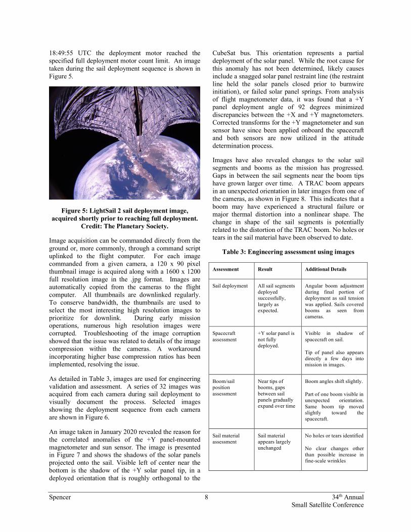
The LightSail 2 flight team successfully commanded solar sail deployment on July 23, 2019. At 18:46:11 UTC a command was sent to initiate the deployment of the four booms that pull out solar sail segments. At
Spencer 8 34th Annual Small Satellite Conference
18:49:55 UTC the deployment motor reached the specified full deployment motor count limit. An image taken during the sail deployment sequence is shown in Figure 5.
Figure 5: LightSail 2 sail deployment image, acquired shortly prior to reaching full deployment.
Credit: The Planetary Society.
Image acquisition can be commanded directly from the ground or, more commonly, through a command script uplinked to the flight computer. For each image commanded from a given camera, a 120 x 90 pixel thumbnail image is acquired along with a 1600 x 1200 full resolution image in the .jpg format. Images are automatically copied from the cameras to the flight computer. All thumbnails are downlinked regularly. To conserve bandwidth, the thumbnails are used to select the most interesting high resolution images to prioritize for downlink. During early mission operations, numerous high resolution images were corrupted. Troubleshooting of the image corruption showed that the issue was related to details of the image compression within the cameras. A workaround incorporating higher base compression ratios has been implemented, resolving the issue.
As detailed in Table 3, images are used for engineering validation and assessment. A series of 32 images was acquired from each camera during sail deployment to visually document the process. Selected images showing the deployment sequence from each camera are shown in Figure 6.
An image taken in January 2020 revealed the reason for the correlated anomalies of the +Y panel-mounted magnetometer and sun sensor. The image is presented in Figure 7 and shows the shadows of the solar panels projected onto the sail. Visible left of center near the bottom is the shadow of the +Y solar panel tip, in a deployed orientation that is roughly orthogonal to the
CubeSat bus. This orientation represents a partial deployment of the solar panel. While the root cause for this anomaly has not been determined, likely causes include a snagged solar panel restraint line (the restraint line held the solar panels closed prior to burnwire initiation), or failed solar panel springs. From analysis of flight magnetometer data, it was found that a +Y panel deployment angle of 92 degrees minimized discrepancies between the +X and +Y magnetometers. Corrected transforms for the +Y magnetometer and sun sensor have since been applied onboard the spacecraft and both sensors are now utilized in the attitude determination process.
Images have also revealed changes to the solar sail segments and booms as the mission has progressed. Gaps in between the sail segments near the boom tips have grown larger over time. A TRAC boom appears in an unexpected orientation in later images from one of the cameras, as shown in Figure 8. This indicates that a boom may have experienced a structural failure or major thermal distortion into a nonlinear shape. The change in shape of the sail segments is potentially related to the distortion of the TRAC boom. No holes or tears in the sail material have been observed to date.
Table 3: Engineering assessment using images
Assessment Result Additional Details
Sail deployment All sail segments deployed successfully, largely as expected.
Angular boom adjustment during final portion of deployment as sail tension was applied. Sails covered booms as seen from cameras.
Spacecraft assessment
+Y solar panel is not fully deployed.
Visible in shadow of spacecraft on sail.
Tip of panel also appears directly a few days into mission in images.
Boom/sail position assessment
Near tips of booms, gaps between sail panels gradually expand over time
Boom angles shift slightly.
Part of one boom visible in unexpected orientation. Same boom tip moved slightly toward the spacecraft.
Sail material assessment
Sail material appears largely unchanged
No holes or tears identified
No clear changes other than possible increase in fine-scale wrinkles

Spencer 9 34th Annual Small Satellite Conference
Figure 6: Images from Camera 1 (top) and Camera 2 (bottom) during sail deployment July 23, 2019. No corrections have been made to the fisheye images. Spectraline that constrained panels in stowed configuration
prior to deployment can be seen in Camera 1 images.
Figure 7: Image showing shadows of the deployed solar panels projected onto the sail, confirming
partial deployment of the +Y solar panel. Credit: The Planetary Society.
Figure 8: Camera 2 image showing TRAC boom in unexpected location. Credit: The Planetary
Society.
In addition to their engineering validation application, images also are crucial to public outreach, increasing awareness, interest, and excitement in this public-supported mission and solar sailing in general. The LightSail 2 flight team can specify the time at which an image is acquired, and a variety of locations are targeted, based upon cloud cover and lighting assessments. Since the spacecraft is not fully three-axis controlled, exact viewing angles cannot be controlled, however, the opposing cameras often yield Earth images with the sail in the foreground. Examples of images used for public relations purposes are shown in Figures 9 and 10.
Figure 9: Camera 2 image showing the Red Sea and the Nile. Credit: The Planetary Society.
Spencer 10 34th Annual Small Satellite Conference
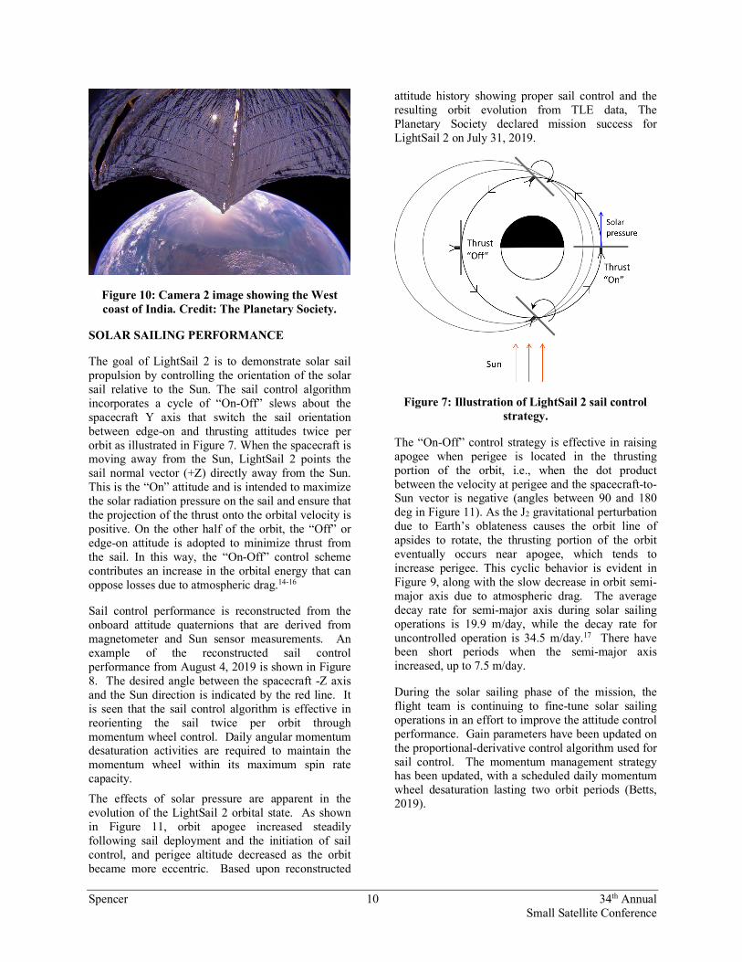
Figure 10: Camera 2 image showing the West coast of India. Credit: The Planetary Society.
SOLAR SAILING PERFORMANCE
The goal of LightSail 2 is to demonstrate solar sail propulsion by controlling the orientation of the solar sail relative to the Sun. The sail control algorithm incorporates a cycle of “On-Off” slews about the spacecraft Y axis that switch the sail orientation between edge-on and thrusting attitudes twice per orbit as illustrated in Figure 7. When the spacecraft is moving away from the Sun, LightSail 2 points the sail normal vector (+Z) directly away from the Sun. This is the “On” attitude and is intended to maximize the solar radiation pressure on the sail and ensure that the projection of the thrust onto the orbital velocity is positive. On the other half of the orbit, the “Off” or edge-on attitude is adopted to minimize thrust from the sail. In this way, the “On-Off” control scheme contributes an increase in the orbital energy that can oppose losses due to atmospheric drag.14-16
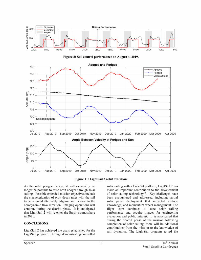
Sail control performance is reconstructed from the onboard attitude quaternions that are derived from magnetometer and Sun sensor measurements. An example of the reconstructed sail control performance from August 4, 2019 is shown in Figure 8. The desired angle between the spacecraft -Z axis and the Sun direction is indicated by the red line. It is seen that the sail control algorithm is effective in reorienting the sail twice per orbit through momentum wheel control. Daily angular momentum desaturation activities are required to maintain the momentum wheel within its maximum spin rate capacity.
The effects of solar pressure are apparent in the evolution of the LightSail 2 orbital state. As shown in Figure 11, orbit apogee increased steadily following sail deployment and the initiation of sail control, and perigee altitude decreased as the orbit became more eccentric. Based upon reconstructed
attitude history showing proper sail control and the resulting orbit evolution from TLE data, The Planetary Society declared mission success for LightSail 2 on July 31, 2019.
Figure 7: Illustration of LightSail 2 sail control strategy.
The “On-Off” control strategy is effective in raising apogee when perigee is located in the thrusting portion of the orbit, i.e., when the dot product between the velocity at perigee and the spacecraft-to-Sun vector is negative (angles between 90 and 180 deg in Figure 11). As the J2 gravitational perturbation due to Earth’s oblateness causes the orbit line of apsides to rotate, the thrusting portion of the orbit eventually occurs near apogee, which tends to increase perigee. This cyclic behavior is evident in Figure 9, along with the slow decrease in orbit semi-major axis due to atmospheric drag. The average decay rate for semi-major axis during solar sailing operations is 19.9 m/day, while the decay rate for uncontrolled operation is 34.5 m/day.17 There have been short periods when the semi-major axis increased, up to 7.5 m/day.
During the solar sailing phase of the mission, the flight team is continuing to fine-tune solar sailing operations in an effort to improve the attitude control performance. Gain parameters have been updated on the proportional-derivative control algorithm used for sail control. The momentum management strategy has been updated, with a scheduled daily momentum wheel desaturation lasting two orbit periods (Betts, 2019).
Spencer 11 34th Annual Small Satellite Conference
Figure 8: Sail control performance on August 4, 2019.
Figure 11: LightSail 2 orbit evolution.
As the orbit perigee decays, it will eventually no longer be possible to raise orbit apogee through solar sailing. Possible extended mission objectives include the characterization of orbit decay rates with the sail to be oriented alternately edge-on and face-on to the aerodynamic flow direction. Imaging operations will continue during the deorbit phase. It is anticipated that LightSail 2 will re-enter the Earth’s atmosphere in 2021.
CONCLUSIONS
LightSail 2 has achieved the goals established for the LightSail program. Through demonstrating controlled
solar sailing with a CubeSat platform, LightSail 2 has made an important contribution to the advancement of solar sailing technology13. Key challenges have been encountered and addressed, including partial solar panel deployment that impacted attitude knowledge, and momentum wheel management. The flight team continues to tune solar sailing performance and acquire images for engineering evaluation and public interest. It is anticipated that during the deorbit phase of the mission following completion of solar sailing, there will be additional contributions from the mission to the knowledge of sail dynamics. The LightSail program raised the
Jul 2019 Aug 2019 Sep 2019 Oct 2019 Nov 2019 Dec 2019 Jan 2020 Feb 2020 Mar 2020 Apr 2020690
695
700
705
710
715
720
725
730
735
Altit
ude
[km
]
Apogee and PerigeeApogeePerigeeMean altitude
Jul 2019 Aug 2019 Sep 2019 Oct 2019 Nov 2019 Dec 2019 Jan 2020 Feb 2020 Mar 2020 Apr 20200
50
100
150
Angl
e [d
eg]
Angle Between Velocity at Perigee and Sun
Sail deployment

Spencer 12 34th Annual Small Satellite Conference
profile of solar sailing with the public as well as with the technical community. In the process the mission has excited the public about space exploration. Importantly, the LightSail program has been funded entirely through private donors, with contributions from more than 50,000 people around the world. The program acted as a pathfinder for public funding of exciting, high-risk technology/science missions.
Acknowledgments The authors would like to thank the donors and members of The Planetary Society, and the Kickstarter campaign contributors, who supported the LightSail program. Also, we are grateful for the crucial assistance of the University Nanosat Program, AFRL, the Prox-1 team, the U.S. Department of Defense Space Test Program, and the USAF 18th Space Control Squadron. We also thank NASA’s Near Earth Asteroid Scout team for informative discussions and a long-term collaboration through a NASA Space Act Agreement.
References 1. Friedman, L., “Human Spaceflight, From Mars
to the Stars,” The University of Arizona Press, Tucson, Arizona, 2015.
2. Alhorn, D. C., Casas, J. P., Agasid, E. F., Adams, C. L., Laue, G., Kitts, C., and O'Brien, S. "NanoSail-D: The Small Satellite That Could!," 25th Annual AIAA/USU Conference on Small Satellites. 2011.
3. Tsuda, Y., Mori, O., Funase, R., Sawada, H., Yamamoto, T., Saiki, T., Endo, T., and Kawaguchi, J. "Flight status of IKAROS deep space solar sail demonstrator," Acta Astronautica Vol. 69, No. 9-10, 2011, pp. 833-840. doi: 10.1016/j.actaastro.2011.06.005
4. Sawada, H., Mori, O., Shirasawa, Y., Miyazaki, Y., Natori, M., Matunaga, S., Furuya, H., and Sakamoto, H. "Mission Report on The Solar Power Sail Deployment Demonstration of IKAROS," 52nd AIAA/ASME/ASCE/AHS/ASc Structures, Structural Dynamics and Materials conference. Vol. AIAA 2011-1887, Denver, Colorado, 2011.
5. Shirasawa, Y., Mori, O., Sawada, H., Chishiki, Y., Kitamura, K., and Kawaguchi, J. i. "A Study on Membrane Dynamics and Deformation of Solar Power Sail Demonstrator "IKAROS"," 53rd AIAA/ASME/ASCE/AHS/ASC Structures,
Structural Dynamics and Materials Conference. Vol. AIAA 2012-1747, Honolulu, Hawaii, 2012.
6. Spencer, D.A., Johnson, L., and Long, A.C., “Solar Sailing Technology Challenges,” Journal of Aerospace Science and Technology, Vol. 93, Oct. 2019, 10.1016/j.ast.2019.07.009
7. Betts, B., Nye, B., Greeson, E., Vaughn, J., Chute, R., Spencer, D.A., Ridenoure, R.W., Munakata, R., Wong, S.D., Diaz, A., Stetson, D.A., Foley, J.D., Bellardo, J.M., and Plante, B.A., “LightSail 1 Mission Results and Public Outreach Strategies,” 4th International Solar Sailing Symposium, Kyoto, Japan, January 2017.
8. Ridenoure, R., Munakata, R., Diaz, A., Wong, S., Plante, B., Stetson, D., Spencer, D., and Foley, J., “LightSail Program Status: One Down, One to Go,” SSC15-V-3, 29th Annual AIAA/USU Conference on Small Satellite, Logan, Utah, August 2015.
9. Ridenoure, R., Spencer, D.A., Stetson, D.A., Betts, B., Munakata, R., Wong, S.D., Diaz, A., Plante, B., Foley, J.D, and Bellardo, J.M., “Status of the Dual CubeSat LightSail Program,” AIAA SPACE 2015 Conference and Exposition, Pasadena, CA, August-September 2015.
10. Ridenoure, R., Munakata, R., Diaz, A., Wong, S., Plante, B., Stetson, D., Spencer, D., and Foley, J., “Testing The LightSail Program: Demonstrating Solar Sailing Technology Using a CubeSat Platform,” Journal of Small Satellites, Vol. 5, No. 3, October 2016.
11. Spencer, D.A., Chait, S.B., Schulte, P.Z., Okseniuk, K.J., and Veto, M., “Prox-1 University-Class Mission to Demonstrate Automated Proximity Operations,” Journal of Spacecraft and Rockets, Vol. 53, Iss. 5, pp. 847-863, September 2016, 10.2514/1.A33526.
12. Okseniuk, K.J., Chait, S.B., Schulte, P.Z., and Spencer, D.A., “Prox-1: Automated Proximity Operations on an ESPA Class Platform,” SSC15-IX-4, 29th Annual AIAA/USU Conference on Small Satellite, Logan, Utah, August 2015.
13. Chait, S., Spencer, D.A., “Prox-1: Automated trajectory control for on-orbit inspection,” 37th Annual American Astronautical Society

Spencer 13 34th Annual Small Satellite Conference
Guidance and Control Conference, Breckenridge, Colorado, February 2014.
14. Betts, B., Spencer, D., Nye, B., Munakata, R., Bellardo, J.M., Wong, S.D., Diaz, A., Ridenoure, R.W., Plante, B.L., Foley, J.D., Vaughn, J., “LightSail 2: Controlled Solar Sailing Using a CubeSat,” 4th International Solar Sailing Symposium, Kyoto, Japan, January 2017.
15. Plante, B.A., Spencer, D.A., Betts, B., Chait, S., Bellardo, J.M., Diax, A., Pham, I., “LightSail 2 ADCS: From Simulation to Mission Readiness,” 4th International Solar Sailing Symposium, Kyoto, Japan, January 2017.
16. Betts, B., Spencer, D., Bellardo, J., Nye, B., Diaz, A., Plante, B., Mansell, J., Fernandez, M., Gillespie, C., Garber, D., “LightSail 2: Controlled Solar Sailing Propulsion Using a CubeSat,” 70th International Astronautical Congress, Washington, D.C., October 2019.
17. Mansell, J., Spencer, D.A., Plante, B.A., Diaz, A., Fernandez, M., Bellardo, J.M., Betts, B., Nye, B., “Orbit and Attitude Performance of the LightSail 2 Solar Sailing Spacecraft,” AIAA Science and Technology Forum and Exposition, Orlando, FL, January 2020.