Embed Size (px)
Citation preview
Paper ID #8129
The LowCost Vertical Axis Wind Turbine Project: An exercise in learningacross disciplines
Dr. Narayanan M. Komerath, Georgia Institute of Technology
This is a student-led paper guided by Professor Komerath. Dr. Komerath is a professor of aerospaceengineering at Georgia Institute of Technology, and director of the Micro Renewable Energy SystemsLaboratory. He has over 300 publications, over 120 of them peer-reviewed, plus 3 US Patents, and hasguided 15 PhDs , 50+ MS and over 160 undergraduate research special problem projects. He is a formerChair of the Aerospace Division.
Akshay Milind Pendharkar, Georgia Institute of Technology
An undergraduate at the Daniel Guggenheim School of Aerospace in Georgia Tech, Akshay Pendharkarhas been working with the Experimental Aerodynamics and Concepts Group (EACG) for over two years.As an international student from India he is scheduled to graduate in May 2013.
Vrishank Raghav, Georgia Institute of Technology
c©American Society for Engineering Education, 2013
Page 23.1222.1
The Low-Cost Vertical Axis Wind Turbine Project- An Exercise in Learning Across Disciplines
Abstract This is a student-led paper describing a multi-year hands-on project. The low-cost Vertical Axis Wind Turbine (VAWT) is a research and development testbed, aimed to refine analyses, design features and construction techniques that will go into devices suitable for use by a family. The testbed integrates knowledge from various disciplines and is used to build experience and capabilities. This paper describes how the student team, mostly undergraduates, participating in this project have been learning what they need to make progress, and to make the innovations necessary for success. The paper traces the evolution of the multi-year student project, and summarizes recent experience of the team that is taking the design to field test readiness. Issues such as safety training, development and usage of skills in using hands-on and analytical tools, and the process of team organization and progress monitoring, are all discussed. Prior work on these topics is extracted and summarized as appropriate. The educational aspects of the project are then discussed, in the context of the resources and practices that we have been developing, to facilitate innovation in multidisciplinary endeavors. Introduction This is a student-led paper describing a multi-year hands-on project. One of the five testbeds being developed at the Micro Renewable Energy Laboratory at our institution, is a low-cost Vertical Axis Wind Turbine (VAWT). Micro wind turbines with power levels from a few watts to a few kilowatts promise a power source for the needs of a small family. They are often located a horizontal axis wind turbine (HAWT) on a tall tower or pole. To reduce the investment and obtrusiveness of such devices, rooftop horizontal axis wind turbines have been developed. While relatively efficient, these turbines operate at high tip speeds, and hence must be located well above reach of residents and pets. VAWTs operate at much lower tip speeds, and are suitable to locate closer to the ground. Blades can be made of less expensive materials, failure modes are generally benign compared to those of HAWTs (no flying swords). However their operation is complex, and their efficiency may not be as high as those of horizontal axis machines. Market Realities Questions from a reviewer warrant a brief digression into the market realities of micro renewable power generators. A news report in Britain in the early 2000s cited the dire danger to the emerging renewable energy industry that results as purchasers of power generators experience
Page 23.1222.2
performance and cost recovery far below advertised levels. An informal survey by a high school student at our lab, conducted in the summer of 2011, studied the advertised performance (rated power), rated windspeed and capture area of wind turbines over a large range of sizes. He found that for wind turbines with power levels on the order of 1 MW, rated power claims were quite conservative when viewed against the wind energy contained in the capture area, and the Betz Limit1,2 of roughly 60% efficiency. However, for small devices, the advertised rated power often appeared to be the power generated at maximum survivable wind speed, not at the rated wind speed. In several cases it was higher than the maximum wind power flowing through the capture area of the device. This confusion appears to stem from lack of regulation: the government fixed the rated wind speed of 12 mph, but does not require that the rated power be the value at the rated wind speed. More recently, vendors educating customers on the realities of small wind turbines3, confirm these fears. A rigorous test of a sophisticated rooftop HAWT market entry4 showed serious problems in achieving the performance and cost recovery that were found advertised by retail vendors. This is typical of market entries in this field, which may partly account for the low market penetration of such devices. Vertical Axis Wind Turbine Features Small VAWTs are often of the Savonius5 type, and are derived from ancient water wheel bucket turbines: they operate on the difference in drag between the blade that advances into the wind and the one that is driven by the wind. The rotor tip speed is limited to be below the wind speed. However, such turbines are simple and start themselves at low wind speeds. The Darrieus VAWT6 is much more complex. In this design, power is generated from the lift operating on blades. Gorlov7 claims a peak conversion efficiency of 35% with a Darrieus design using a helical blade design in steady water flow. Practical efficiency values in fluctuating low-altitude winds is usually much lower. The theory of Darrieus turbines shows that optimal power generation occurs when the rotor tip speed is 3 to 5 times the wind speed. This means that Darrieus machines require some other means of starting. At low tip speed ratios, power generation comes primarily from two sectors around the rotor azimuth, with stalling and negative torque occurring in some other regions. Complex solutions to this problem include a motor to drive the machine up to optimal tip speed ratio, and cyclic pitch control using cams or servo motors. These drive the cost of the machine up considerably. Analytical approaches must be quite sophisticated. Other than the obvious variation with blade azimuth that occurs at all conditions, operation at high tip speed ratio implies further complexity. The same fluid packet can encounter more than one blade. Streamtube curvature through the machine must be considered, as well as energy extraction from the streamtube by preceding blades. The net result is that it is a challenging undertaking to develop a cost-effective micro wind turbine, and especially so in the case of the VAWT. Conventional turbines alleviate such issues using complex means such as pitch control using cam/linkage arrangements or using servo motors. These drive costs far beyond what can be made viable in the mass marketplace, and impose maintenance and repair/replacement costs that are beyond the reach of many anticipated user communities. Our team from the beginning, emphasized the use of inexpensive materials, commonly-available (bicycle-based) moving parts, and local construction/ repair/ maintenance suitability. The emphasis on sustainable architecture with parts and materials easily disposed at the end of their lifetimes, also imposed constraints.
Page 23.1222.3
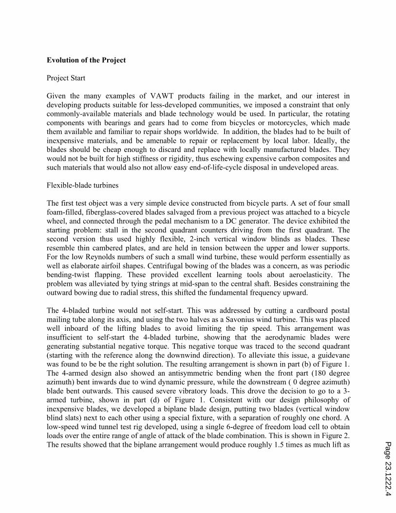
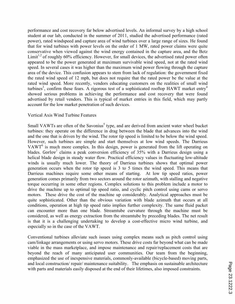
Evolution of the Project Project Start Given the many examples of VAWT products failing in the market, and our interest in developing products suitable for less-developed communities, we imposed a constraint that only commonly-available materials and blade technology would be used. In particular, the rotating components with bearings and gears had to come from bicycles or motorcycles, which made them available and familiar to repair shops worldwide. In addition, the blades had to be built of inexpensive materials, and be amenable to repair or replacement by local labor. Ideally, the blades should be cheap enough to discard and replace with locally manufactured blades. They would not be built for high stiffness or rigidity, thus eschewing expensive carbon composites and such materials that would also not allow easy end-of-life-cycle disposal in undeveloped areas. Flexible-blade turbines The first test object was a very simple device constructed from bicycle parts. A set of four small foam-filled, fiberglass-covered blades salvaged from a previous project was attached to a bicycle wheel, and connected through the pedal mechanism to a DC generator. The device exhibited the starting problem: stall in the second quadrant counters driving from the first quadrant. The second version thus used highly flexible, 2-inch vertical window blinds as blades. These resemble thin cambered plates, and are held in tension between the upper and lower supports. For the low Reynolds numbers of such a small wind turbine, these would perform essentially as well as elaborate airfoil shapes. Centrifugal bowing of the blades was a concern, as was periodic bending-twist flapping. These provided excellent learning tools about aeroelasticity. The problem was alleviated by tying strings at mid-span to the central shaft. Besides constraining the outward bowing due to radial stress, this shifted the fundamental frequency upward. The 4-bladed turbine would not self-start. This was addressed by cutting a cardboard postal mailing tube along its axis, and using the two halves as a Savonius wind turbine. This was placed well inboard of the lifting blades to avoid limiting the tip speed. This arrangement was insufficient to self-start the 4-bladed turbine, showing that the aerodynamic blades were generating substantial negative torque. This negative torque was traced to the second quadrant (starting with the reference along the downwind direction). To alleviate this issue, a guidevane was found to be be the right solution. The resulting arrangement is shown in part (b) of Figure 1. The 4-armed design also showed an antisymmetric bending when the front part (180 degree azimuth) bent inwards due to wind dynamic pressure, while the downstream ( 0 degree azimuth) blade bent outwards. This caused severe vibratory loads. This drove the decision to go to a 3-armed turbine, shown in part (d) of Figure 1. Consistent with our design philosophy of inexpensive blades, we developed a biplane blade design, putting two blades (vertical window blind slats) next to each other using a special fixture, with a separation of roughly one chord. A low-speed wind tunnel test rig developed, using a single 6-degree of freedom load cell to obtain loads over the entire range of angle of attack of the blade combination. This is shown in Figure 2. The results showed that the biplane arrangement would produce roughly 1.5 times as much lift as
Page 23.1222.4

a single blade, thus making it worthwhile if blade cost could be kept low, as with local blade manufacture.
Page 23.1222.5
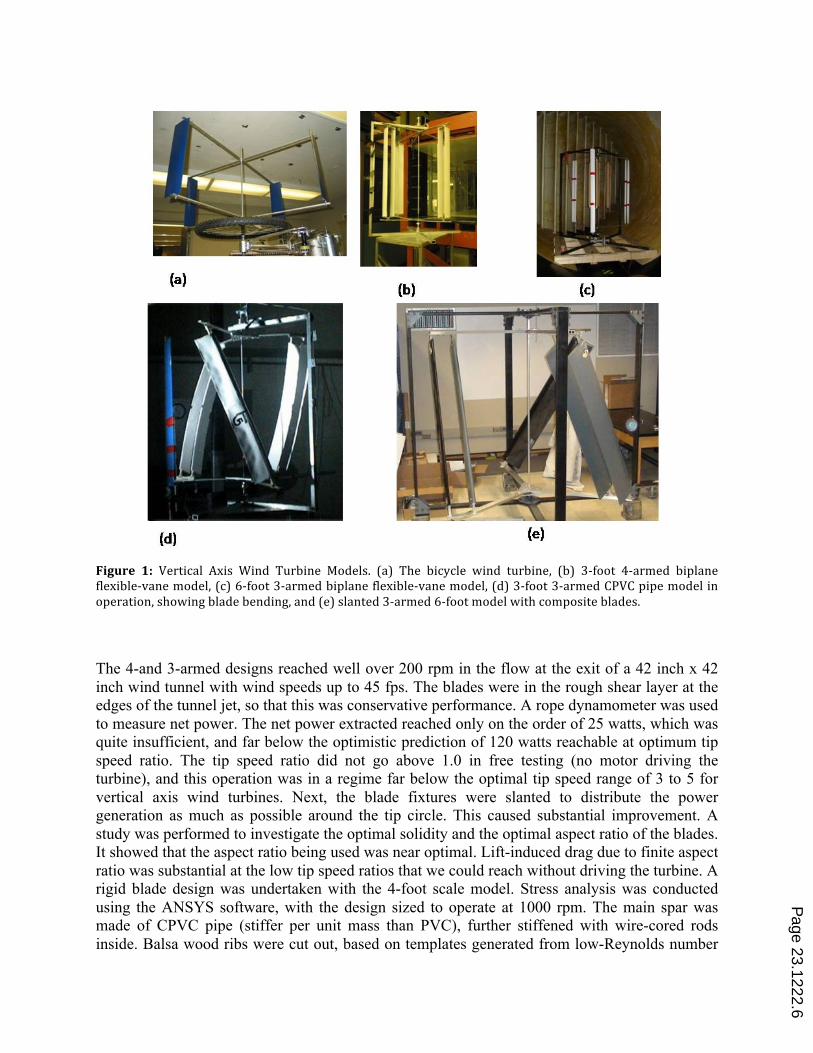
Figure 1: Vertical Axis Wind Turbine Models. (a) The bicycle wind turbine, (b) 3-‐foot 4-‐armed biplane flexible-‐vane model, (c) 6-‐foot 3-‐armed biplane flexible-‐vane model, (d) 3-‐foot 3-‐armed CPVC pipe model in operation, showing blade bending, and (e) slanted 3-‐armed 6-‐foot model with composite blades. The 4-and 3-armed designs reached well over 200 rpm in the flow at the exit of a 42 inch x 42 inch wind tunnel with wind speeds up to 45 fps. The blades were in the rough shear layer at the edges of the tunnel jet, so that this was conservative performance. A rope dynamometer was used to measure net power. The net power extracted reached only on the order of 25 watts, which was quite insufficient, and far below the optimistic prediction of 120 watts reachable at optimum tip speed ratio. The tip speed ratio did not go above 1.0 in free testing (no motor driving the turbine), and this operation was in a regime far below the optimal tip speed range of 3 to 5 for vertical axis wind turbines. Next, the blade fixtures were slanted to distribute the power generation as much as possible around the tip circle. This caused substantial improvement. A study was performed to investigate the optimal solidity and the optimal aspect ratio of the blades. It showed that the aspect ratio being used was near optimal. Lift-induced drag due to finite aspect ratio was substantial at the low tip speed ratios that we could reach without driving the turbine. A rigid blade design was undertaken with the 4-foot scale model. Stress analysis was conducted using the ANSYS software, with the design sized to operate at 1000 rpm. The main spar was made of CPVC pipe (stiffer per unit mass than PVC), further stiffened with wire-cored rods inside. Balsa wood ribs were cut out, based on templates generated from low-Reynolds number
Page 23.1222.6
airfoil shapes. The ribs were attached to the pipe using small metal brackets. The pipe spar was connected at the ends to CPVC pipe tees to allow setting attitude, and the tees were attached using metal brackets to the aluminum frame. The airfoil skins were PVC roof flashing sheets, bent over the ribs to generate the airfoil shape, and stapled at the trailing edge to provide a sharp trailing edge. The blades were slanted. This design is shown in part (d) of Figure 1, and is the current state of the blade design. It still meets the criteria of low cost and ease of manufacture. When translated to the field, the blades will presumably be built using natural fibers and carpentry instead of CPVC. A separate 6-foot VAWT was built, with all parameters scaled up from the 3-foot machine, except that the blades were built of composites and the frame was made of steel. This device is designed to operate in winds of up to 80 mph, and is sized to be tested in the test section of our 7' x 9' wind tunnel.
Figure 2: Components used in the VAWT testbed project. Top from L-R: Set up with a single 6-dof load cell, to measure the lift, drag and pitching moment of blades at the exit of the 42-inch wind tunnel at the School of AE at Georgia Tech, through a wide range of angle of attack. (b) Nylon pulley used to transmit power from the VAWT. (c)Circuit board developed to switch from being driven by a motor, to driven by the wind, (d) parts of the attachment stand.
Page 23.1222.7
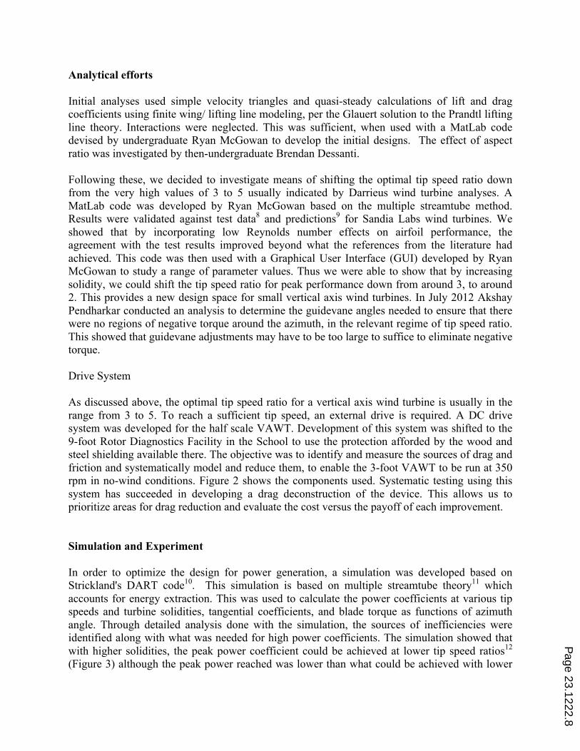
Analytical efforts Initial analyses used simple velocity triangles and quasi-steady calculations of lift and drag coefficients using finite wing/ lifting line modeling, per the Glauert solution to the Prandtl lifting line theory. Interactions were neglected. This was sufficient, when used with a MatLab code devised by undergraduate Ryan McGowan to develop the initial designs. The effect of aspect ratio was investigated by then-undergraduate Brendan Dessanti. Following these, we decided to investigate means of shifting the optimal tip speed ratio down from the very high values of 3 to 5 usually indicated by Darrieus wind turbine analyses. A MatLab code was developed by Ryan McGowan based on the multiple streamtube method. Results were validated against test data8 and predictions9 for Sandia Labs wind turbines. We showed that by incorporating low Reynolds number effects on airfoil performance, the agreement with the test results improved beyond what the references from the literature had achieved. This code was then used with a Graphical User Interface (GUI) developed by Ryan McGowan to study a range of parameter values. Thus we were able to show that by increasing solidity, we could shift the tip speed ratio for peak performance down from around 3, to around 2. This provides a new design space for small vertical axis wind turbines. In July 2012 Akshay Pendharkar conducted an analysis to determine the guidevane angles needed to ensure that there were no regions of negative torque around the azimuth, in the relevant regime of tip speed ratio. This showed that guidevane adjustments may have to be too large to suffice to eliminate negative torque. Drive System As discussed above, the optimal tip speed ratio for a vertical axis wind turbine is usually in the range from 3 to 5. To reach a sufficient tip speed, an external drive is required. A DC drive system was developed for the half scale VAWT. Development of this system was shifted to the 9-foot Rotor Diagnostics Facility in the School to use the protection afforded by the wood and steel shielding available there. The objective was to identify and measure the sources of drag and friction and systematically model and reduce them, to enable the 3-foot VAWT to be run at 350 rpm in no-wind conditions. Figure 2 shows the components used. Systematic testing using this system has succeeded in developing a drag deconstruction of the device. This allows us to prioritize areas for drag reduction and evaluate the cost versus the payoff of each improvement. Simulation and Experiment In order to optimize the design for power generation, a simulation was developed based on Strickland's DART code10. This simulation is based on multiple streamtube theory11 which accounts for energy extraction. This was used to calculate the power coefficients at various tip speeds and turbine solidities, tangential coefficients, and blade torque as functions of azimuth angle. Through detailed analysis done with the simulation, the sources of inefficiencies were identified along with what was needed for high power coefficients. The simulation showed that with higher solidities, the peak power coefficient could be achieved at lower tip speed ratios12 (Figure 3) although the peak power reached was lower than what could be achieved with lower
Page 23.1222.8
solidity13. By using guide vanes to turn the flow at various azimuth locations, the torque produced by the blade could be kept positive all around the azimuth.
Figure 3: Effects of solidity on the operation of a Vertical Axis Wind Turbine Blade aerodynamic characteristics of the vertical blind slats and later S2027 airfoil blade designs were measured using a special rig using a single 6-dof load cell, placed at the exit of the 42 inch wind tunnel as shown in part (b) of Figure 1. This apparatus was designed and built by the student team. Drag deconstruction experiments were performed in the 9-foot Rotor Diagnostics Facility, with shaft encoders used to obtain RPM, and electric power measured using multimeters. A single 12-volt deep cycle automobile battery was used first, and then supplemented with another one in series to deliver 24 volts. Multi-Disciplinary Aspects The testbed approach to research provides a focus for students to bring their skills to bear as they seek out new knowledge. As discussed above, this one project involves the content of several courses in the aerospace curriculum. This is briefly considered below:
1. The project delved into the aerodynamics of airfoil sections and finite wings, both experimentally and using analyses from coursework. This included choosing airfoil sections, measuring characteristics, correcting finite wing data to validate airfoil section performance against published results including Reynolds number dependence, calculating lift, drag and pitching moment, optimizing the Savonius drag tubes for self-
Page 23.1222.9
starting, constructing turbomachine velocity diagrams to find regions of driving and dragging, and considering streamtube interactions and power extraction effects.
2. Unsteady aerodynamics effects appear in the optimal range of operation where the tip is moving 3 to 5 times as fast as the wind. This is complex, graduate-level aerodynamics. The VAWT testbed provides a convenient platform to introduce the physics.
3. Statics and Strength Of Materials: The project required innovating on materials, and using flexible components of unknown strength, checking measured strength against estimates. Composite principles were used to obtain strength where needed. The design and construction of the 6-foot turbine required students to use CAD and structural analysis software packages, along with common-sense calculations.
4. Dynamics and vibrations: Moment of inertia of each component was measured and computed to model the dynamic system. Vibrations had to be diagnosed and reduced.
5. Mechanical design and graphics skills were refined. 6. The fabrication of the various parts was done in consultation and iteration with the
professional machinists in the Machine Shop. 7. Composite wing construction technology was learned under the guidance of graduate
student Rafael Lozano, who had experience of doing this professionally on co-op assignments in industry. This involved the proper ways to mix resin and hardener, cutting wood templates, fixing ribs, leading edge and trailing edge pieces, filling foam, laying the fiberglass cloth, covering with the resin mix, curing, sanding with protective equipment and cleanup processes, and verifying the shape and refining it. Some structural testing was done to verify the amount of deflection that occurred, in order to validate the predictions from the ANSYS code.
8. Stress analysis of complex systems was learned on the job using the ANSYS code available through the university's software licensing server. The knowledge required to operate the code was transferred between team members.
9. Structural testing was done using improvised test rigs involving cantilever and simply suspended beams and suspended weights.
10. The simulation was developed in MATLAB as well as in FORTRAN. For the team, FORTRAN was a newly-learned tool.
11. The motor, generator and associated circuitry were mastered. A switching system to go between operation as a driven machine and a generator, was obtained with the help of the Electrical Engineering instructor and class.
12. Data acquisition and analysis is very hard to fit into the standard curriculum. The VAWT testbed provides a focal point to teach about the Nyquist sampling criteria, Wiener-Khintchine theorem relating frequency domain and time domain statistical quantities, statistical averaging of data, and all other aspects of signal processing.
13. Figure of Merit approach to system improvement. The reason for the low values of power measured became evident when the simulation reached a fidelity where we could predict our machine's expected performance. Due to the low tip speed ratio that could be achieved in unpowered testing, the performance was quite poor, but quite accurately matched the predicted performance.
14. Socioeconomic aspects: The peculiar design constraints adopted, are driven by conceptual models of the end user customers of such systems. It is a good exercise in socioeconomics for engineering students to investigate the validity of these assumptions.
Page 23.1222.10
15. Business modeling: There are good reasons why HAWTS and VAWTS are not seen in large numbers or widespread use at the small scale level. These have to do with the difficulty of building and installing micro wind turbines in an economical manner, with payoff within 3 years. Venture capital models do not work in this environment, and so the business developer must seek more appropriate models.
Educational Assessment Assessing student performance quantitatively on research projects, poses quite a challenge. The success or failure of the device or system itself cannot be used as a metric, since there is no guarantee that the chosen problem has a satisfactory solution. Thus the grading must be based on the instructor's understanding the effort and thought that have been invested by the student into the project. It is difficult to separate out this aspect objectively from the status of the project itself, as there is a common tendency to blame the student for not trying hard enough to make the project succeed. On the other hand, it is often true that nonlinear effort and initiative by the student is what makes projects succeed. Our 3-fold approach is:
1. A rigorous reporting scheme with weekly report updates, as well as regular weekly face-to-face meetings with the student, so that there is continual assessment and feedback on the thought and effort going into the project, as well as to discuss alternative approaches.
2. To provide continuity across semesters, a system of documentation has been developed. Work done each week is added into the project document. All of the VAWT associated files are open to the members of the current VAWT team who are required to review all of the previous work carried out. The project leader is an undergraduate provides continuity and ensures transfer of knowledge.
3. With both of the above established, tie the grading to the initiative and effort shown, but be strict about regularity and completeness of reporting and meeting attendance. Having said that, it remains true that with good, regular attention and reporting, most students on Research Special Problems should be able to earn A grades. However, we do have the experience of having had to give grades over the whole spectrum from F to A.
Conclusions This case study documents the multi-year process by which a small device is developed using a team of mostly undergraduates. The detailed process exhibits several positive and negative features of the constantly changing team, where a great deal of the effort goes into the students' learning, as is appropriate for our environment. The particular constraints on the sytem are driven by the needs of the anticipated customer environment. These do introduce challenges, as well as exciting possibilities for innovation. Acknowledgements This work was supported under a NASA grant monitored by Mr. Tony Springer. The authors are also grateful for the help of Mr. James Steinberg of the School of Electrical and Computer Engineering at Georgia Tech, who assisted in developing the charging circuit.
Page 23.1222.11
References 1 Okulov, Valery L., and Gijs AM van Kuik: The Betz–Joukowsky limit: on the contribution to rotor aerodynamics by the British, German and Russian scientific schools. Wind Energy 15.2 (2012): 335-‐344. 2 Bergey, K. H.: The Lanchester-‐Betz limit. Journal of Energy 3 (1979): 382-‐384. 3 Anon. The Truth About Small Wind Turbines. http://www.solacity.com/smallwindtruth.htm Seen March 19, 2013. 4 Anon: Shopping Was Hardly A Breeze For Our Secret Shoppers. Consumer Reports magazine, October 2011. 5 Hansen, A. C., and Butterfield, C.P.: Aerodynamics of horizontal-‐axis wind turbines.} Annual Review of Fluid Mechanics 25.1 (1993): 115-‐149. 6 Kato, Y., Seki, K. and Shimizu, Y. : Vertical axis wind turbine. US Patent 4247253. 1981. 7 Gorlov, Alexander M., and Valentin M. Silantyev: Limits of the turbine efficiency for free fluid flow. Journal of Energy Resources Technology 123 (2001): 311-‐317. 8 Sheldahl, R.E. and Klimas, R.C. : Aerodynamic characteristics of seven symmetrical airfoil sections through 180-‐degree angle of attack for use in aerodynamic analysis of vertical axis wind turbines. Technical Report SAND80-‐2114, Sandia National Laboratories, 1981 9 Islam, M., Ting, D.S.K., and Fartaj, A.: Aerodynamic models for Darrieus-‐type straight-‐bladed vertical axis wind turbines. Renewable and Sustainable Energy Reviews, 12:1087-‐1109, 2008. 10 Strickland, J. H.: A Performance Prediction Model Using Mutiple Streamtubes}. Report SAND75-‐0431, Sandia National Laboratories, October 1975 11 Hirsch, H. and Mandal, A.C.: A cascade theory for the aerodynamic performance of Darrieus wind turbines. Wind Engineering, 11(3):164-‐175, 1987. 12 Templin, R. J.: Aerodynamic performance theory for the NRC vertical-‐axis wind turbine. NASA STI/Recon Technical Report N 76 (1974): 16618. 13 McGowan, R., Raghav, V. S., Komerath, N. M. Optimization of a Vertical Axis Micro Wind Turbine for Low Tip Speed Ratio Operation. Proceedings of the AIAA IECEC Conference, Atlanta, GA, 2012.
Page 23.1222.12