Embed Size (px)
Citation preview

THE MclNTOSH C32 SOLID STATE STEREO PREAMPLIFIER
Reading Time: 44 Minutes Price $1.25

WARNING: TO PREVENT FIRE OR SHOCKHAZARD, DO NOT EXPOSE THIS UNIT TORAIN OR MOISTURE.
The Mclntosh you have purchased has a serial number located onthe rear panel of the chassis.Record that serial number herefor future references. The model and serial number are importantto you for any future service.

Your C 32 Stereo Preamplifier wil lgive you many years of pleasant andsatisfactory performance. If youhave any questions, please contact:
CUSTOMER SERVICEMclntosh Laboratory Inc.2 Chambers StreetBinghamton, New York 13903Phone: 607-723-3512
Take Advantage of 3 yearsof FREE Service...Fill in the Application NOW.
ContentsINTRODUCTION 2
HOW TO INSTALL 2
HOW TO CONNECT 4
USING THE FRONT PANEL CONTROLS 8USING THE PUSHBUTTONS 11BALANCING YOUR STEREO 12
LISTENING TO YOUR STEREO 12
PERFORMANCE LIMITS AND RATINGS 13
PERFORMANCE CHARTS 14, 15TECHNICAL DESCRIPTION 16
BLOCK DIAGRAM 19
THREE YEAR SERVICE CONTRACTAn application for a FREE THREE YEAR SERVICE CONTRACT is included with this manual.
The terms of the contract are:
1. Mclntosh will provide all parts, materials andlabor needed to return the measured perfor-mance of the instrument to the original per-formance limits free of any charge. TheSERVICE CONTRACT does not cover anyshipping costs to and from the authorizedservice agency or the factory.
2. Any Mclntosh authorized service agencywil l repair Mclntosh instruments at normalservice rates. To receive the free serviceunder the terms of the SERVICE CONTRACT,the SERVICE CONTRACT CERTIFICATE mustaccompany the instrument when taken tothe service agency.
3- Always have service done by a Mclntoshauthorized service agency. If the instrumentis modified or damaged, as a result of un-authorized repair the SERVICE CONTRACTwill be cancelled. Damage by improper use or
mishandling is not covered by the SERVICECONTRACT.
4. The SERVICE CONTRACT is issued to you asthe original purchaser. To protect you frommisrepresentation this contract cannot betransferred to a second owner.
5. For your protection Mclntosh selects onlydealers who have technical competence toguide purchasers fairly, and provide servicewhen necessary. To receive the SERVICECONTRACT your purchase must be madefrom a Mclntosh franchised dealer.
6. Your completely filled in application for aSERVICE CONTRACT must be postmarkedwithin 30 days of the date of purchase of theinstrument.
7. To receive the SERVICE CONTRACT all in-formation on the application must be filledin. The SERVICE CONTRACT will be issuedwhen the completely filled in application isreceived at Mclntosh Laboratory Incorporatedin Binghamton, New York.
Copyright © 1977 by Mclntosh Laboratory Inc. 1

IntroductionThe Mclntosh C 32 preamplifier provides the most com-
prehensive range of functions and control options. Manyof these are new in a preamplifier. The C 32 can onlyserve you best when you understand what its functionsare and what it is designed to do. Spend some time withthis manual and get to know how this preamplifier works.
The C 32 is a "dual" stereo preamplifier with a built-inMONITOR POWER AMPLIFIER. There are two totally inde-pendent left and right stereo program lines runningthrough the preamplifier. One program line is the LISTENprogram line, the other is the RECORD program line. Eachprogram line can select its own program source from anyconnected input signal—i.e. PHONO, TUNER, AUX, orTAPES 1, 2 or 3 without interference with the other pro-gram line.
The output of the LISTEN program line is affected byall the front panel controls (except the RECORD switch)and is fed to the OUTPUT MAIN and/or OUTPUT 1 and 2jacks as selected by front panel pushbuttons. The outputof the RECORD program line is not affected by front panelcontrols (except the RECORD switch) and is fed to a l lOUTPUT RECORD jacks.
The MONITOR AMPLIFIER program may be selectedfrom either the LISTEN or RECORD program lines. Sepa-rate GAIN controls for LEFT AND RIGHT MONITOR AM-PLIFIER are located on the top panel. The signal selectedfor the MONITOR AMPLIFIER is fed to the front panelHEADPHONE jacks and the rear panel OUTPUT LINE andMONITOR OUTPUT connectors.
How to installThe PANLOC system of installing equipment conve-
niently and securely is a direct result of Mclntosh research.By depressing the two PANLOC buttons on the front panelof the C 32, the instrument either can be locked firmly inplace or unlocked so that the chassis can be slid forward,giving you easy access to the top and rear panels.
The trouble-free life of an electronic instrument isgreatly extended by providing sufficient ventilation toprevent the buildup of high internal temperatures thatcause deterioration. Allow enough clearance so that coolair can enter at the bottom of the cabinet and be ventedfrom the top. With adequate ventilation the instrumentcan be mounted in any position. The recommended mini-mum space for installation is 15 inches (38.1 cm) deep,17 inches (43.2 cm) wide, and 6 inches (15.2 cm) high.
To install the instrument in a Mclntosh cabinet, followthe instructions that are enclosed with the cabinet. Forany other type of installation:
1. Unpack from CartonRemove the instrument PANLOC brackets, hardwarepackage, and mounting template from the carton. Re-move the C 32 from its plastic bag and place it upsidedown on the shipping pallet; unscrew the four plasticfeet from the bottom of the chassis.
2. Mark for PositionPlace the mounting template in position to cover thearea of the cabinet panel where the instrument is to beinstalled, and tape it in place. The broken lines thatrepresent the outline of the rectangular cutout alsorepresent the outside dimensions of the chassis. Makesure these lines clear shelves, partitions, or any equip-ment. With the template in place, first mark the six Aand B holes and the four small holes that locate thecorners of the cutout. Then, join the four corner mark-ings with pencil lines, using the edge of the templateas a straightedge.
2

3. Drill HolesUsing a drill with a 3/16 inch bit held perpendicular tothe panel, drill the six A and B holes. Then, using a drillbit slightly wider than the tip of your saw blade, drillone hole at each of two diagonally opposite corners. Theholes should barely touch the inside edge of the pencilledoutline. Before taking the next step, make sure thatthe six A and B holes have been drilled.
4. Saw Panel CutoutSawing carefully on the inside of the pencilled lines,first make the two long cuts and then the two short.After the rectangular opening has been cut out, use afile to square the corners and smooth any irregularitiesin the cut edges.
5. Install Mounting StripsIn the hardware package you will find two mountingstrips and two sets of machine screws. For panels thatare less than ½ inch thick, use the ¾ inch screws; forpanels that are more than ½ inch thick, use the 1¼ inchscrews.
Starting at the right-hand side of the panel, insert ascrew of the proper length into the center hole in thepanel, marked B on the template. On the back of thepanel, align a mounting strip with the holes in the paneland tighten the screw until the screwhead is pulledslightly into the wood.
Repeat this procedure to attach the mounting stripto the left side of the panel.
6. Attach PANLOC BracketsUsing two screws of the proper length in the A holes oneach side, attach the PANLOC brackets to the cabinetpanel; the short flange is mounted against the front(face) of the cabinet panel. The screws pass through thePANLOC bracket flange, the cabinet panel, and thenthrough the mounting strips previously mounted.
7. Install InstrumentGuide the AC power cord through the panel opening tothe back of the cabinet; then, slide the instrument intothe opening carefully so that the rails on the bottom ofeach side of the chassis engage the tracks on the mount-ing brackets. Continue to slide the instrument into thecabinet until it is stopped by the adjust position latches.Press the latches inward, this permits the instrument toslide into the cabinet until its front panel is flush withthe cabinet panel. Depress the PANLOC buttons at thelower left and right corners of the instrument panel tolock the unit firmly in the cabinet. Depressing thePANLOC buttons again wi l l unlock the instrument sothat it can be slid forward to the adjust position;pressing inward on the adjust position latches permitsremoval from the cabinet
3

How to ConnectCONNECTING A TURNTABLE TO PHONO 1
Connect the cable from the "left" channel of the turn-table into the INPUT L PHONO 1 jack.
Connect the cable from the "right" channel of the turn-table into the INPUT R PHONO 1 jack.
PHONO 2 is provided for the use of a second turntable.Connect the cable from the "left" channel of the turn-
table into the INPUT L PHONO 2 jack.Connect the cable from the "right" channel of the turn-
table into the INPUT R PHONO 2 jack.
On the rear panel are two green AC power outlets anda slide switch marked AUTO/MANUAL. Plug the AC powercables from the turntable into the green TURNTABLEPOWER outlets on the rear panel. When the switch is inthe AUTO position, power to the black AC power out-lets, can be controlled by the front panel POWER switchor by the current drawn by a turntable plugged intothe green TURNTABLE POWER outlets. The current sens-ing green AC power outlets will control the AC powerto the entire system from the AC power on/off switch onthe turntable. When the turntable is turned off with itsown AC power switch, no current is drawn which causesthe current sensing relays in the C 32 to turn oft all ACpower to the system. With the AUTO/MANUAL switch in theMANUAL position, AC power to the system will be controlledby the front panel POWER pushbutton only.
Some turntables have electronic circuits that draw currentall the time. To use these turntables the AUTO/MANUALswitch must be in the MANUAL position.
The green AC power outlets are protected with a oneampere fuse. Any increase in the value of this fuse willaffect the operation of the sensing circuit and can causesevere damage.
GROUND CONNECTIONA single ground post is provided. Grounds for turntables,
record changers, tape decks, etc. should be connected tothis post. The left and right program cables and the groundwire from that source should be wound or twisted together.To avoid hum, make sure the ground wire does not makeany connections to the shields of the left and right programcables between the program source and the C 32.
CONNECTING A STEREO TUNERConnect the cable from the "left" channel tuner output
to the INPUT L TUNER jack.Connect the cable from the "right" channel tuner output
to the INPUT R TUNER jack.
AUX—Any high level program source such as a tuner,a TV set or a tape recorder can be connected to the INPUTAUX jacks.
CONNECTING TAPE RECORDERSTo Record:
Connect a cable from the OUTPUT L TAPE 1 jack to the
left high level input of the tape recorder.
Connect a cable from the OUTPUT R TAPE 1 jack to theright high level input of the tape recorder
Connect second and third tape recorders in the samefashion to the TAPE 2 and TAPE 3 outputs.
To Playback/Monitor:
Connect the cable from the left channel output of a taperecorder to the INPUT L TAPE 1.
Connect the cable from the right channel output of a taperecorder to the INPUT R TAPE 1.
Connect second and third tape recorders in the samefashion to the TAPE 2 and TAPE 3 INOUT jacks.
TAPE RECORDER FRONT PANEL CONNECTIONInputs and outputs for TAPE 3 are available at the TAPE 3
IN-OUT jacks on the front panel just left of the pushbuttons.This allows rapid, temporary connections to TAPE 3 positionwithout getting at the rear panel, A metal shielded Vstereo phone plug is used for best shielding—similar tothe plugs used on low impedance headphones. Connectionsfollow the industry standards and are tip: left signal, ring:right signal, and, sleeve: common ground
Connecting a Tape Recorder to the Listen Program Line
Connect a cable from the OUTPUT 1 —LEFT jack to theleft high level input of the tape recorder
Connect a cable from the OUTPUT 1 —RIGHT jack to theright high level input of the tape recorder.
Output signal will be ted to the tape recorder when thefront panel pushbutton OUTPUT 1 is pushed in.
CONNECTING THE C 32 TO POWER AMPLIFIERSConnect the OUTPUT MAIN jacks to the input of a
stereo power amplifier. The Left MAIN jack is connectedto the left amplifier input jack. The Right MAIN jack isconnected to the right amplifier input jack.
Two additional stereo power amplifiers may be con-nected in the same fashion to the OUTPUT 1 and OUTPUT 2jacks. Audio output signal is supplied to these jacks onlywhen front panel pushbutton SPEAKER/OUTPUT 1 and 2pushbuttons are pressed IN. The input impedance of theamplifiers used should be 5,000 ohms or greater.
SPEAKER CONTROL RELAYTo control loudspeakers by use of SPEAKER/OUTPUT 1
and 2 pushbuttons on the front panel an accessory MclntoshSCR (SPEAKER CONTROL RELAY) is needed. Plug the specialcable from the SCR control into the SPEAKER CONTROLRELAY receptacle. The speakers are then connected to theSCR control.
The SCR has two AC power outlets that provide addi-tional capacity of 2400 watts. Use these outlets to supplyAC power to amplifiers or other components to be con-trolled by the ON OFF cycle of the C 32. Use the SCRwhenever the total load to be switched by the C 32 exceedsits rating of 600 watts.
4

TAPE RECORDER 3
T U N E R
FM ANTENNA
AC POWER TOTAPE RECORDERS.TUNERS, POWERAMPLIFIERS.TOTAL OF 600 WATTS.FOR MORE AC POWERUSE THE SCR SPEAKERCONTROL RELAY
AC POWER
AC POWER
T U R N T A B L E #2
TURNTABLE #1
5
TAPER E C O R D E R2
TAPER E C O R D E R
1

USE
OFPU
SHBU
TTO
NSSP
EAKE
R/O
UTP
UT
REM
OTE
SPEA
KERS
SPEA
KER
CO
NN
ECTI
ON
S
TO A
C LI
NE
6

MAI
N SP
EAKE
RS
MO
NIT
OR
AMPL
IFIE
R SP
EAKE
RS
7

Using the Front Panel ControlsLISTEN and RECORD Input Selector Switches
The control at the left top of the front panel selects theinput for the LISTEN program line. The left bottom controlselects the input for the RECORD program line. Both op-erate in the same manner.
MODE SELECTORThe MODE SELECTOR facilitates the accurate adjustment
of a stereo system for differences caused by room acous-tics, loudspeaker placement and the other componentsused in the system.
The MODE SELECTOR switch affects the program onthe LISTEN program line only and connects the programto the loudspeaker in seven ways:
L to L and R: Connects the left input to both loudspeakers.
R to L and R: Connects the right input to both loud-speakers.
STEREO REV: Connects the left input to the right loud-speaker and the right input to the left loudspeaker.
STEREO: Connects the left input to the left loudspeakerand the right input to the right loudspeaker.
MONO (L + R): Adds the left and right inputs together andconnects to both loudspeakers.
L + R to L: Connects the left plus right program to theleft loudspeaker only.
L - R to R: Connects the left plus right program to theright loudspeaker only.
EQUALIZER FREQUENCY ControlsEach of five EQUALIZER FREQUENCY controls raises or
lowers a band of frequencies centered on the frequencymarked above the control. Both left and right channels ofthe LISTEN program line are affected. The center, or flat,position of the control has a detent for easy reference.
Use the EQUALIZER FREQUENCY controls to modify thesound and balance of material. Here are some suggestionsfrom which to start:
ProblemBass too weakMale vocalist needs reinforcingFemale reinforcingHum on programViolins, trumpets dullDrum "brushes" not audible
Equalizer CorrectionRaise 30 and/or 150Raise 150Raise 500Reduce 30 and LF FILTERRaise 1500Raise 10 K
To prevent interference from subsonic and supersonicsignals, the C 32 includes subsonic and supersonic filtersthat attenuate signals below 20 Hz and above 20,000 Hz.They are bypassed when the EQ OUT pushbutton is pressedIN which extends the frequency response to 10 Hz to100,000 Hz.
BALANCE and LOUDNESSThe BALANCE and LOUDNESS controls are concentric.
The BALANCE control (large outer knob) adjusts for equalvolume of either the left or right channels. The volume ofthe channels can be varied relative to each other withoutaffecting their combined volume.
LEFT . . . turning the control to the left accents the leftchannel by reducing the right channel output.
RIGHT . . . turning the control to the right accents theright channel by reducing the left channel output.
LOUDNESSThe LOUDNESS control (small center knob) increases
both bass and treble frequencies of both channels as it isturned clockwise. Adjustment of the LOUDNESS controlallows life-like frequency balance when playing musicsoftly. Its contour is the same, regardless of the positionof the volume control. This contour is accurately modelledafter the family of "Equal Loudness" curves identified byFletcher and Munson.
8

EXPANDERThe EXPANDER affects both channels of the LISTEN
program line only. The circuit enables you to correct forthe compression that is imposed on most of the programmaterial available—records, tapes and FM. Compressionis used for many practical reasons but limits the dynamicrange—and, therefore, the realism—of the music. Programsvary in their need for expansion. Live recordings may notneed any at all. Rotation of the EXPANDER causes theloudness of the program to be affected logarithmically.The point at which operation of the expander starts isselected by the rotary LEVEL MATCH control on the toppanel. The attack speed of the expander is set with theSPEED switch on the top panel. Settings of FAST, NORMand SLOW change the attack time of the expander.
As the EXPANDER control is rotated clockwise the circuitacts in two ways:
1. Loudness is reduced for signals below a predeterminedset level. The farther below set level the program is, themore the loudness is reduced.
2. Loudness is increased for signals above set level. Thegreater the program is above set level, the more theloudness is increased.
The amount of loudness expansion imposed on incomingsignals is determined by the position of the EXPANDERcontrol. Clockwise rotation increases the effect. As theEXPANDER knob is rotated clockwise, undesirable noisessuch as hum, scratch and hiss are reduced. The chartsshow the action of the EXPANDER CIRCUIT. When rotatedfully counterclockwise, the front panel EXPANDER knobactivates a switch which completely by-passes all EX-PANDER circuitry.
The LEVEL MATCH control on the top panel of the C 32adjusts the set level. This is the point above and belowwhich expansion is introduced when the EXPANDER knobis turned clockwise. Set the LEVEL MATCH controls for eachchannel while listening to a program. Switch the EXPANDERin and out. The average sound level of the system should bethe same with the EXPANDER knob in the desired positionof EXPANSION as it is in the bypass (OFF) position.
9

A. To reduce noise (hum, hiss or scratch)
1. Select the desired program source with LISTEN frontpanel selector switch.
2. Switch top panel SPEED control to NORM.
3. Increase VOLUME control during a quiet passage ofthe program until noise is clearly audible.
4. Rotate EXPANDER control clockwise until the noiseis acceptably reduced.
5. Adjust the LEVEL MATCH controls.
B. To improve the "live" sound of recorded or transmittedprogram material:
1. Select LISTEN input.
2. Switch top panel SPEED control to NORM.
3. Increase VOLUME to satisfactory level.
4. Rotate the EXPANDER control clockwise until thedynamic range of the music, the ratio of loud to softis correct for you.
5. Adjust the LEVEL MATCH controls as described pre-viously.
By using the EXPANDER controls in conjunction with theEQUALIZER FREQUENCY controls, the C 32 may be usedto de-emphasize and decompress disc and tape programmaterial.
HEADPHONE JacksThe stereo HEADPHONE jacks are driven by the built-in
MONITOR AMPLIFIER. Either LISTEN or RECORD programscan be heard depending on the position of the INPUTswitch on the MONITOR AMPLIFIER located on the toppanel. The LEFT and RIGHT GAIN controls regulate head-phone volume:
A. In conjunction with the main front panel VOLUME con-trol if the top panel INPUT switch is in LISTEN position,
B. Exclusively if the INPUT switch is in RECORD position.
The upper HEADPHONE jack is used to feed electrostaticheadphones. It is fed directly by the MONITOR AMPLIFIER.Electrostatic headphones require more power than dynamictype headphones as a rule. The lower headphone jack isused to feed low impedance dynamic headphones. It isfed by the MONITOR AMPLIFIER through a matching net-work.
MONITOR AMPLIFIER
Although its primary purpose is to drive the headphonejacks, the MONITOR AMPLIFIER may additionally be used:
1. To listen, on speakers, to any of the inputs connected tothe C 32 without the use of a separate stereo poweramplifier. Stereo loudspeakers can be connected to therear panel 8 ohm terminals. The program source for theMONITOR AMPLIFIER may be selected from either theLISTEN program line or the RECORD program line bymeans of the top panel INPUT switch. Beside the INPUTswitch are LEFT GAIN and RIGHT GAIN controls. Theycontrol the volume of the respective channels of theMONITOR AMPLIFIER.
2. To drive a 600 ohm unbalanced line connected toOUTPUT LINE jacks.
3. The extensive flexibility of the C 32 permits many otherpossible uses of the MONITOR AMPLIFIER such asadding a reverberation device, time delay or "ambience"accessory unit, discrete 4-channel, etc.
10

Using the Pushbuttons
PHONO 1-2The PHONO 1-2 pushbutton selects from either PHONO 1
or PHONO 2 inputs. When the button is out—the indicatorabove the 1 will light and the PHONO 1 signals will beconnected to the LISTEN and RECORD switches. When thepushbutton is in, the indicator above the 2 will light andthe PHONO 2 inputs will be connected to the LISTEN andRECORD switches.
RECORD MONITORWhen pressed IN, the RECORD MONITOR pushbutton
switches the LISTEN input to the output of the RECORDprogram line. In the IN position the program heard on theLISTEN program line is the program on the RECORD pro-gram line.
EQ OUTThe EQ OUT pushbutton operates to bypass the program
equalizers, the LF and HF filters and the subsonic andsupersonic filters on the LISTEN program line. With theEQ OUT pushbutton pressed IN, the total bandwidth ofthe C 32 is 10 to 100,000 Hz. The indicator light abovethe EQ OUT pushbutton is illuminated when the pushbuttonis pressed IN indicating that the EQUALIZER FREQUENCYand the HF and LF FILTERS are removed from the circuit.
LF FILTERThe LF FILTER affects only the LISTEN program line
when pressed in. With the LF FILTER IN all frequenciesbelow 50 Hz are attenuated at the rate of 12 dB per octave.Use it to reduce undesirable low frequency noise such asrumble or acoustic feedback.
HF FILTERThe HF FILTER affects only the LISTEN program line.
With the HF FILTER IN all frequencies above 7,000 Hz areattenuated at the rate of 12 dB per octave. Use it to reduceundesirable high frequency noise such as record surfacenoise or tape hiss.
SPEAKER/OUTPUT 1 and 2
The SPEAKER/OUTPUT 1 and 2 pushbuttons operateonly on the LISTEN program line. Each serve dual purposes.
When pressed IN, they
A. Connect the LISTEN program to the OUTPUT 1 and 2jacks on the rear panel. Sound can thus be switched onand off in areas served by additional amplifiers con-nected to these jacks. Typical uses would be the switch-ing of music to selected living areas, a swimming poolor an outdoor recreation area.
B. Control the operation of a SCR relay when it is pluggedinto the rear panel SPEAKER CONTROL RELAY socket.
The SCR controls the audio to two pairs of stereo loud-speakers. The AC power to two AC receptacles on the SCRis controlled by the ON-OFF cycle of the C 32. The totalAC power capacity of the receptacles is 2400 watts.
POWERThe POWER switch energizes the C 32 circuits and sup-
plies AC power to the black rear panel AC power outlets.The black AC power outlets are not fused.
11

Balancing Your StereoThe performance and enjoyment of a stereo system is
greatly increased when the sound is properly balanced.Balance is affected by many things including room acous-tics, furniture placement, room shape, small differences inloudspeakers, etc. The input gain controls on your stereopower amplifier should be used to balance the system.The BALANCE control on the C 32 should be used to adjustfor imbalance in program material.
1. Set the MODE to MONO.
2. Play a familiar recording.
3. Turn the BALANCE control to the 12 o'clock position.
4. While the program is playing, stand between the twoloudspeakers. Listen for a difference in loudness be-tween speakers. Balance the system by adjusting thecontrols on the power amplifiers. Next, set the MODEselector to STEREO. If there is then a difference inloudness turn the BALANCE control toward the speakerthat is not as loud. Adjust the BALANCE control untilthe sound is equally loud from both speakers.
Listening to Your StereoLISTENING TO STEREO RECORDS
Turn the LISTEN selector to PHONO 1, or PHONO 2,whichever is connected to the turntable you wish to hear.
Set the MODE SELECTOR to STEREO.
Adjust the VOLUME control to the desired volume.
LISTENING TO MONOPHONIC RECORDSTurn the LISTEN selector to PHONO 1 or PHONO 2,
whichever is connected to the turntable you wish to hear.
Turn the MODE SELECTOR to MONO
Adjust the VOLUME control to the desired volume,
LISTENING TO A TUNER
Turn the LISTEN selector to TUNER
Adjust the volume to a comfortable level.
LISTENING TO A TAPE RECORDERThree tape recorders can be used with the C 32.
Turn the LISTEN selector to TAPE 1, 2 or 3 whichever isconnected to the tape recorder you wish to hear.
Turn the MODE SELECTOR to STEREO or MONO, depend-ing on the program on the tape
Adjust the VOLUME control to the desired volume.
TAPE MONITORINGA program being recorded may be monitored either as
it is fed to the tape recorder , or, in the case of tape recordershaving separate playback heads and associated preampli-fiers, directly oft the tape. To monitor the program beingted to the tape recorder, press the RECORD MONITORpushbutton IN, To monitor from the playback head of thetape recorder as the program is being recorded turn theLISTEN switch to TAPE 1. 2 or 3.
USING THE LISTEN CONTROLS FOR TAPE RECORDING
To modify a program before recording, the OUTPUT 1or 2 outputs on the program line may be fed to a tape re-corder. For connection instructions, see page 4 under "Howto Connect."
The controls in the LISTEN program line are all availableto alter the signal before recording Note that once re-cording has started, the controls will change the programto the tape recorder. Since the available signal outputfrom the OUTPUT 1 or OUTPUT 2 is much higher than theoutput available from the OUTPUT TAPE 1, TAPE 2, orTAPE 3 jacks, be sure the signal does not overload the taperecorder input,
HOW TO COPY TAPEThe tape to be copied is ted to INPUT TAPE 1 Set the
RECORD selector to TAPE 1. The signal available at theOUTPUT TAPE 2 and 3 jacks is the playback of TAPE 1Recording is done on either recorder 2 or 3, or both andcan be monitored on the LISTEN program line by selectingthe appropriate TAPE position of the LISTEN knob.
12

Performance Limits and RatingsPerformance Limits die the maximum deviation fromperfection permitted for a Mclntosh instrument. We promiseyou that your C 32 must be capable of performance at orexceeding these limits or you get your money back.
FREQUENCY RESPONSE+0 -0.5 dB 20 Hz to 20,000 Hz(with equalizer out: +0 -1 dB from 10 Hz to 100,000 Hz)
DISTORTION.05% maximum, at rated output level, 20 Hz to 20,000 Hz
INPUT SENSIT IV ITY AND IMPEDANCEPHONO 1 and 2 2 millivolts at 47,000 ohms 65 pF,AUXiltary, TUNER TAPE 1, 2 and 3: 250 millivolts at50,000 ohms
HUM AND NOISEAUXiliary, TUNER, TAPE 1, 2 and 3. IHF 100 dB un-weighted--90 dBPHONO 1 and 2 IHF 90 dB, unweighted 80 dB below 10millivolt input or equivalent to less than 1 microvolt at theinput terminals
OUTPUT LEVEL A N D I M P E D A N C EMAIN Output 2.5 volts with rated input, 220 ohms sourceimpedance, to operate into 5,000 ohm or greaterTAPE Output 250 millivolts with rated input to operateinto 5,000 ohms or greater
MONITOR, HEADPHONE, LINE Output: 12watts per channel, continuous, into 8 ohmsat 0,1% harmonic distortion 20 Hz to20,000 Hz or 5 volts RMS into 600 ohmline—level controls provided
PROGRAM EQUALIZERFive, 2 octave frequency bands, each band has 12 dB ofboost or cut at 30, 150, 500, 1500 and 10,000 Hz
LF FILTERFlat or roll-oft at 12 dB per octave below 50 Hz
HF F ILTERFlat or rol l -of f at 12 dB per octave above 7000 Hz
VOLTAGE AMPLIFICATION in Decibels(all equalizers and filters flat)
Input
Auxi l iary, TunerTape 1, 2 or 3Phono 1Phono 2
Main
20 dB
62 dB
Tape1 , 2 , 3
0dB
42 dB
MonitorAmp
20 dB
62 dB
SEMICONDUCTOR COMPLEMENT67 Transistors35 Integrated Circuits62 Diodes
2 Field Effect Transistors1 Silicon Controlled Rectifier (SCR)
AC POWER OUTLETS2 automatic current sensing (green)4 switched (black)
POWER R E Q U I R E M E N T S120 volts, 50/60 Hz, 25 to 85 wat ts
MECHANICAL INFORMATIONSIZE: Front panel measures 16 inches wide (40,64 cm) by5-7/16 inches deep (13.81 cm). Chassis measures 15inches wide (38.1 cm) by 5 inches high (12.7 cm) by 13inches deep (33.02 cm), including PANLOC shelf and backpanel connectors Knob clearance required is 1-1/2 inches(3.81 cm) in front of the mounting panel.FINISH: Front panel is anodized gold and black withspecial gold/teal nomenclature illumination. Chassis isblackMOUNTING: Exclusive Mclntosh developed professionalPANLOCWEIGHT, 26 pounds (11.79 kg) net, 36 pounds (16.33 kg)in shipping carton
13

14
Perfo
rman
ce C
harts

15
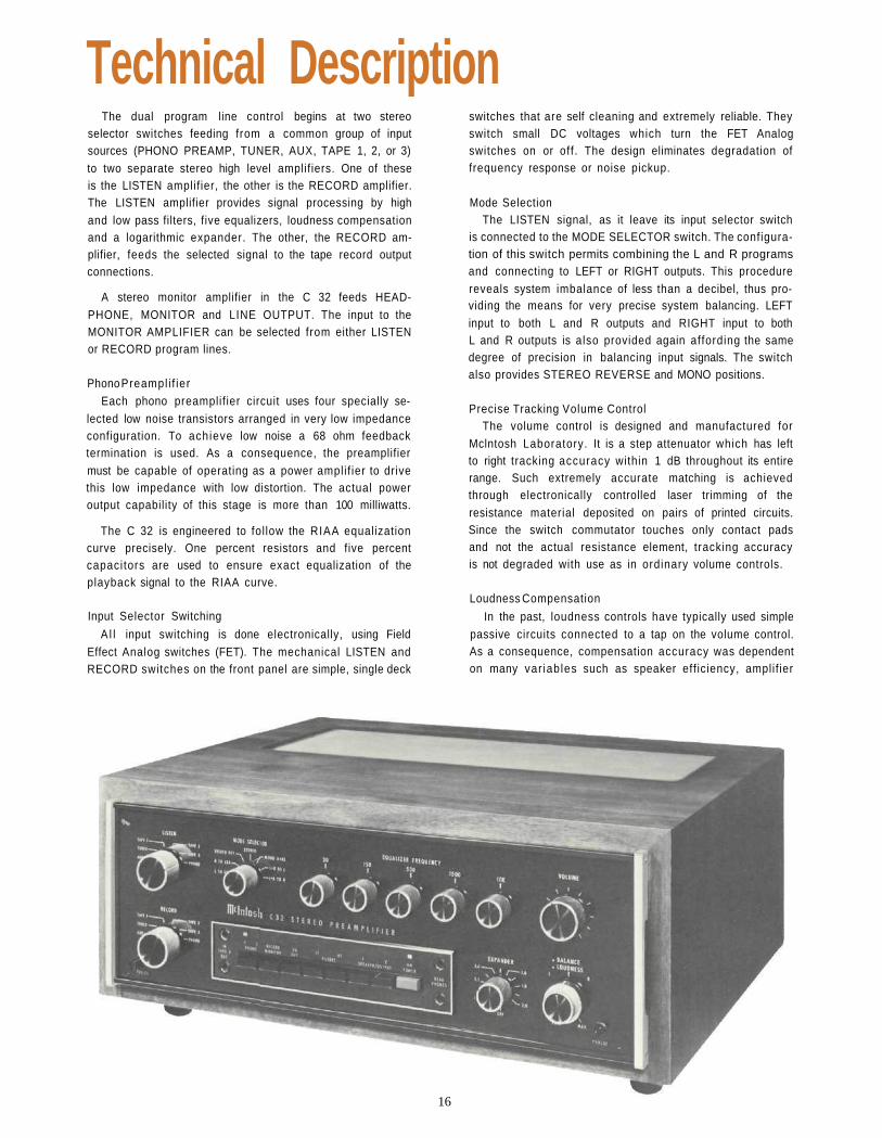
Technical DescriptionThe dual program line control begins at two stereo
selector switches feeding from a common group of inputsources (PHONO PREAMP, TUNER, AUX, TAPE 1, 2, or 3)to two separate stereo high level amplifiers. One of theseis the LISTEN amplif ier, the other is the RECORD amplifier.The LISTEN amplifier provides signal processing by highand low pass filters, five equalizers, loudness compensationand a logarithmic expander. The other, the RECORD am-plifier, feeds the selected signal to the tape record outputconnections.
A stereo monitor amplifier in the C 32 feeds HEAD-PHONE, MONITOR and LINE OUTPUT. The input to theMONITOR AMPLIFIER can be selected from either LISTENor RECORD program lines.
Phono Preampl i f ierEach phono preamplif ier circuit uses four specially se-
lected low noise transistors arranged in very low impedanceconfiguration. To achieve low noise a 68 ohm feedbacktermination is used. As a consequence, the preamplifiermust be capable of operating as a power amplif ier to drivethis low impedance with low distortion. The actual poweroutput capability of this stage is more than 100 milliwatts.
The C 32 is engineered to fol low the RIAA equalizationcurve precisely. One percent resistors and five percentcapacitors are used to ensure exact equalization of theplayback signal to the RIAA curve.
Input Selector Switching
A l l input switching is done electronically, using FieldEffect Analog switches (FET). The mechanical LISTEN andRECORD switches on the front panel are simple, single deck
switches that are self cleaning and extremely reliable. Theyswitch small DC voltages which turn the FET Analogswitches on or off. The design eliminates degradation offrequency response or noise pickup.
Mode SelectionThe LISTEN signal, as it leave its input selector switch
is connected to the MODE SELECTOR switch. The configura-tion of this switch permits combining the L and R programsand connecting to LEFT or RIGHT outputs. This procedurereveals system imbalance of less than a decibel, thus pro-viding the means for very precise system balancing. LEFTinput to both L and R outputs and RIGHT input to bothL and R outputs is also provided again affording the samedegree of precision in balancing input signals. The switchalso provides STEREO REVERSE and MONO positions.
Precise Tracking Volume ControlThe volume control is designed and manufactured for
Mclntosh Laboratory. It is a step attenuator which has leftto right tracking accuracy within 1 dB throughout its entirerange. Such extremely accurate matching is achievedthrough electronically controlled laser trimming of theresistance material deposited on pairs of printed circuits.Since the switch commutator touches only contact padsand not the actual resistance element, tracking accuracyis not degraded with use as in ordinary volume controls.
Loudness Compensation
In the past, loudness controls have typically used simplepassive circuits connected to a tap on the volume control.As a consequence, compensation accuracy was dependenton many var iables such as speaker eff iciency, amplif ier
16

gain and differences in input level.
The C 32 uses active circuitry, electrically independentof the volume control. Close conformity to Fletcher MunsonEqual Loudness Curves is attained regardless of volumecontrol position.
Active Filter CircuitryLoudness, equalizer, and band pass filters of the C 32
are all constructed with ion implanted junction field effectoperational amplifiers (popularly called "Op Amps").These new devices amplify with a 6 dB better signal tonoise ratio than bipolar input op amps.
Program EqualizersTo adjust for program limitations and personal prefer-
ences the C 32 LISTEN program line has a five band boost/cut program EQUALIZER based on resonant circuit opera-tional amplifier. The preamplifier is flat when the EQUAL-IZER controls are at the 12 o'clock position. EQUALIZERcenter frequencies of 30, 150, 500, 1500 and 10,000 Hzwere chosen to cover the audio spectrum in approximatelyequal two octave bandwidths. Maximum boost and cut is12 dB at band centers.
HF and LF FiltersThe HF and LF filters are selected by pushbutton switches
in a manner electrically similar to the program EQUALIZERSand are pushbutton switch selected. The HF filter attenu-ates all frequencies above 5 kHz, reaching a rate of 12 dBper octave, at 7 kHz (at which point attenuation is 3 dBbelow the 5 kHz level). The LF filter attenuates all fre-quencies below 50 Hz, at a rate of 12 dB per octave.
All program EQUALIZERS and HF/LF filters are bypassedwhen the EQ OUT pushbutton switch is depressed. TheEQ OUT switch also removes subsonic and supersonic fil-ters below 20 Hz and above 20,000 Hz, extending totalfrequency response to 10 Hz to 100,000 Hz.
The ExpanderTo overcome the compression imposed in radio broad-
casting and recording, and to reduce hum, scratch and hiss,the C 32 has a logarithmic program expander in theLISTEN program line. Controls are provided to adjust theoperating point, attack time and expansion ratio.
Signal from the equalizer circuit is applied to a voltagecontrolled amplifier (VCA) which operates as a variablegain block. Control voltages for this VCA are developedfrom a sample taken from the output of the equalizer. Theelectronic processing of this sample is detailed. It includesband shaping, logarithmic amplification, full wave rectifi-cation, level setting, expansion ratio regulation, attacktiming, level setting and DC amplification. The resultingvoltage controls the gain of the VCA to cause logarithmicgain reduction below set level and logarithmic expansionabove set level.
A switched bypass link provides a program path aroundthe expander, to maintain a constant signal level with theexpander in or out of the circuit. The gain of the amplifierblock incorporated in the link approximates the gain ofthe expander circuit.
The Record Program LineThe C 32 is designed to permit simultaneous recording
on up to three tape recorders of any program input selectedon the RECORD switch regardless of what is being heardon the LISTEN program line. The RECORD switch selectsits input from the same inputs, but entirely independentlyfrom the LISTEN switch. As this selection is by means ofhigh impedance FET Analog switches, switching to or overan input in use on the LISTEN program line does not causeany audio interference.
Output from the RECORD switch is fed through tapeinterlock switches to the three pairs of tape recorder outputjacks. In the event that one of the tape recorders is chosenas an input signal to the RECORD program line, its asso-ciated tape interlock is opened to prevent feedback throughthat tape recorder back into the C 32 input.
Monitor Amplifier/Headphone Circuits
The C 32 contains a stereo power amplifier which pro-vides adequate power to drive electrostatic headphones.The upper HEADPHONE output jack is connected directlyto this MONITOR AMPLIFIER output, making the full 12watts per channel power available to drive those head-phones which require it. The lower HEADPHONE jack isfed through a network designed to match low impedancedynamic headphones.
In addition, the MONITOR AMPLIFIER may be switchedto either program line, controlled and connected withenough flexibility that several other uses for it are possible.Some of these are:
1. As a preamplifier/power amplifier in a completelyseparate stereo system.
2. To power rear channel speakers when used in a 4-channel discreet system.
3. To operate speakers in another area.
4. To feed a 600 ohm line.
On the rear panel are two green AC power outlets anda slide switch marked AUTO/MANUAL. Plug the AC powercables from the turntable into the green TURNTABLEPOWER outlets on the rear panel. When the switch is inthe AUTO position, power to the black AC power outlets,can be controlled by the front panel POWER switch orby the current drawn by a turntable plugged into thegreen TURNTABLE POWER outlets. The current sensinggreen AC power outlets will control the AC power to theentire system from the AC power on/off switch on theturntable. When the turntable is turned off with its own
17

AC power switch, no current is drawn which causes thecurrent sensing relays in the C 32 to turn off all AC powerto the system.
Special Output SwitchingIn addition to the OUTPUT MAIN jacks, two additional
pairs of output jacks, OUTPUT 1 and OUTPUT 2, are pro-vided. These are individually switched from the frontpanel pushbuttons SPEAKER/OUTPUT. The C 32 outputsignal can be fed to two additional stereo power amplifiersindependent of the main system stereo amplifier. Alter-natively, these outputs may be used to drive reverberationdevices, delay lines, etc. The SPEAKER/OUTPUT pushbuttonswitches provide the voltage to control a SCR speaker con-trol relay.
Power SupplyTo minimize hum pickup—and thus improve signal to
noise ratio—the C 32 power transformer is triple shielded.Shielding includes a copper strap, a silicon steel strap andfinally, a steel outer shell. The transformer output voltageis fed to a full wave bridge with 5,000 microfarad filtercapacitors to provide the plus and minus 24 volts poweringthe MONITOR AMPLIFIER. The plus and minus 18 voltsneeded for low level and op amp stages is derived from the24 volt supply and controlled with integrated circuit vol-tage regulators.
Turn on DelayThe C 32 has transient free turn on and turn off charac-
teristics. A relay, time controlled by a transistor switch,connects the output of the preamplifier to the output jacks.The control to the transistor switch is derived from a longtime constant capacitor charging network that turns therelay on approximately two seconds after the C 32 isturned on. The same circuit has a short turn-off time con-stant which turns off the relay before the preamplifier'smain power supply has had a chance to discharge.
18
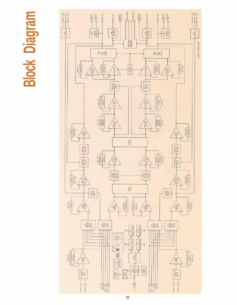
Block
Diag
ram
19

MclNTOSH LABORATORY INC.
2 CHAMBERS ST. BINGHAMTON, N. Y. 13903607-723-3512
The continuous improvement of its products is the policy ofMclntosh Laboratory Incorporated, who reserve the right to
improve design without notice.
Printed in U.S.A.
038-990
BE032003