Embed Size (px)
Citation preview
9th Conference on Computational Methods in Marine Engineering (Marine 2021)
2-4 June 2021, Edinburgh, Scotland, UK
THE MECHANICAL ANALYSIS OF HDPE NET CAGE BY TEST AND CALCULATION
HAIYANG LIU AND XIAOHUA HUANG AND TAIPING YUAN AND YU HU
AND JIEJIN GUO AND GUOLIANG PANG
Sanya Tropical Fisheries Research Institute
Sanya 572018, China
South China Sea Fisheries Research Institute, Chinese Academy of Fishery Sciences
Key Laboratory of South China Sea Fishery Resources Exploitation & Utilization, Ministry of Agriculture and Rural Affairs
Key Laboratory of Open-Sea Fishery Development, Ministry of Agriculture and Rural Affairs
Guangdong Cage Engineering Research Center Guangzhou 510300, China
Key words: Net Cage, Mechanical Test, Structural strength, FEA, HDPE
ABSTRACT To reduce the structural failure risk of net cages under extreme sea conditions, this study analysed the yield phenomenon under mooring constraints and excessive or long-term wave loads. The floating collar deforms by shear when a twisted 1 m for the 8-point type and 5 m for the four point type. The structural strength in the Z-vertical direction is one-fifth of that in the X-horizontal direction. The maximum deformation is mainly on the two ends of the cap ned pipes. The critical points of the guardrail may reach the yield stress when the wave height is 1.1 m, while the height of the floating pipe is 5 m. The float can be damaged more easily when there is torsion or shear deformation caused by irregular waves. The results provide guidelines for the optimised structural design of net cages, which by increasing the number of mooring points and cap neds as well as reducing the welding points and structural mutation points, can improve the ultimate bearing capacity and fatigue reliability of the cage float.
1 Introduction
The high-density polyethylene (HDPE) circular fish cages have remarkable advantages such as high cost-effectiveness, large breeding capacity, and corrosion resistance. To reduce the pressure of inshore limits, the fish cage designs are updated from conventional nearshore to offshore, which must contend with deep-sea high-energy environments (Chu et al., 2020). However, the cage system may be bent or deformed if it cannot bear the excessive loads of the wave environment, especially in the face of super-typhoons, which are considered the main cause of cage damage (Bi et al., 2020). The aquaculture cages systems were listed and classified (Xu and Qin, 2020). The floating system of the fish cage is coordinated with the waves, mooring, and net loads that experience reciprocating motion, so the float may cause fatigue damage due to vibration loads. Especially at present, although the theoretical, numerical, and experimental progress made in the application of porous membranes and net-type structures to fish cages is rapidly increasing (Guo et al., 2020), there is still a lack of
specification and unified standards for transient failure and fatigue reliability. Based on the fluid–structure interactions within cage-based aquaculture, the characteristics of fish cages subjected to external loads were decomposed(Xu and Qin, 2020); then, the mooring constraint and wave load could be calculated by structural force (Wan et al., 2020). Through the static calculation and structural stability analysis, the fish cage motion and structural strength are evaluated, to satisfy safety requirements.
The structural dynamics method in finite element modelling (FEM) has a significant advantage in analysing the risk assessment of fish cage systems, which can greatly promote the further design and optimisation of fish cages. The equilibrium configuration and the tension distribution of the set-net were calculated (Wan et al., 2020). The structural strength of offshore fish farms subjected to supply vessel collisions in Norway was evaluated using nonlinear FEM simulations, and the results were discussed with respect to the impact resistance, energy absorption, and structural damage (Yu et al., 2019). Liu et al. (2017, 2019, 2020) developed a processing method for a floating sample, and carried out mechanical tests to measure the performance parameters of a floating pipe, and the floating failure and fatigue were analysed by combining the measurements with FEM structural simulation. The drag on the cage was measured using a load shackle attached to the towing rope, and the net deformation and cage volume were calculated (Gansel et al., 2018). Moreover, Huang et al. (2020) compared and analysed the test results of mooring force, heave, pitch, and roll of offshore fish farms under different conditions. In addition, the use of the FEM structural mechanics model could effectively study the failure of floating key nodes. The plastic yield simulation of extreme loads based on structural analysis has attracted increasing attention from domestic to foreign experts.
In summary, research on the material and structural mechanical properties of cages is important in domestic and foreign reports; however, the judgement standards for the failure performance of key cage structures are still insufficient, and specific research on the nonlinear failure and fatigue characteristics of fish cages is still needed. To address these issues, this study performs material mechanical tests of tensile, bending, and vibration loading modes and conducts FEM structural simulation on the plastic failure and fatigue evaluation of circular fish cages. Furthermore, the main scale and structure of HDPE fish cage C80 (perimeter of circular cage is 80 m) is investigated to determine if it can withstand the maximum wave level. Through the FEM display dynamics of structural mechanics nonlinear analysis, the key parts of the fish cage that are destroyed during failure are identified, facilitating the development of future improved fish cages.
2 Mechanical numerical computation of the fish cage
2.1. Choice of FEM element for the fish cage
The FEM element type used for the fish cage is selected based on structural geometry, material characteristics, and loading status. The element contacts are classified as having a no separation, frictionless bond. The preferential elements of tetrahedron and hexahedron include Pipe59, Beam161, Mass166, Combi165, and Link160. The details of shell elements and solid elements of the fish cage are as follows. Each Shell163 node has twelve degrees of freedom, which are the translation, velocity, and acceleration of the node in the X, Y, and Z directions and rotation about the X, Y, and Z axes, and the unit supports all nonlinear characteristics for the display dynamics. Shell181 is a 4-node quadrilateral unit, and each node has six degrees of freedom, which
are translations in the X, Y, and Z directions and rotation about the X, Y, and Z axes. The element has the abilities of nonlinear stress stiffening, large deformation, large rotation angle, and large strain. The analysis of the HDPE composite pipe and thin-shell structure of the cage float is appropriate. The Shell281 element has eight nodes, and each node has six degrees of freedom, which are translation in the X, Y, and Z directions and rotation about the X, Y, and Z axes. Solid 187 is a tetrahedral element with ten nodes. Solid185 has eight nodes, each of which has three degrees of freedom of translation in the X, Y, and Z directions, and the element has the ability of super-elasticity, stress hardening, creep, large deformation, and strain.
2.2. Dynamic analysis based on the fish cage model The general equation of fish cage motion is calculated based on modal analysis
theory. [ ] [ ] [ ] ( )M x C x K x F t (1) where F(t) is the external load vector, [M] is the mass matrix, [C] is the damping matrix, [K] is the stiffness matrix, x is the nodal acceleration vector, x is the nodal velocity vector, and x is the nodal displacement vector.
The equation for buckling analysis of cage float is as follows: ([K]+ λi[S]){Ψi}=0 (2) where [K] and [S] are constants, λi is the buckling load multiplier, and {Ψi} is the buckling mode.
The ordinary differential equations (ODEs) involving damping and inertia forces are solved, and the central difference algorithm of the immediate integration method is used to integrate the dynamic equation. The velocity and acceleration are expressed as follows:
1( )
2t t t t tx x x
t
(3)
2
1( 2 )t t t t t tx x x x
t
(4)
Equations (3) and (4) are substituted into Equation (5), and the recurrence formula for solving the solutions at each discrete time point can be obtained:
2 2 2
1 1 2 1 1[ ] ( ) [ ] [ ]
2 2t t t t tM C x F t K M x M C x
t t t t t
(5)
Formula (5) under given initial conditions is used to solve the displacement values of each discrete time point, and the stability condition of the solution is:
ncr
Tt t
(6)
where Tn is the minimum natural vibration period of the FEM system, and ∆tcr is estimated using the following equation:
min
2/ (1 )cr
lt
E
(7)
where lmin is the minimum unit length, ρ is the material density, γ is Poisson's ratio, and E is the elastic modulus.
3 Material test of the fish cage floating collar
3.1. Hydrodynamic test of C80 fish cage mooring force
The wave height of the regular wave was 5–8 m, and the period was 9–11 s. The
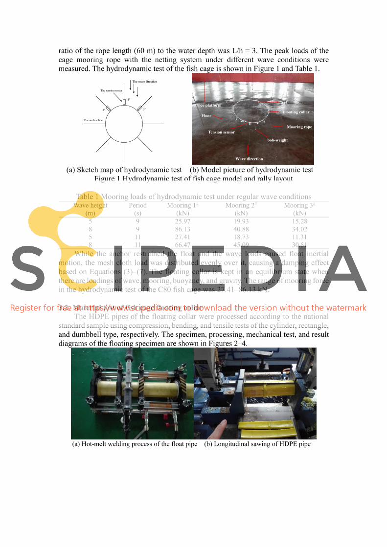
ratio of the rope length (60 m) to the water depth was L/h = 3. The peak loads of the cage mooring rope with the netting system under different wave conditions were measured. The hydrodynamic test of the fish cage is shown in Figure 1 and Table 1.
(a) Sketch map of hydrodynamic test (b) Model picture of hydrodynamic test
Figure 1 Hydrodynamic test of fish cage model and rally layout
Table 1 Mooring loads of hydrodynamic test under regular wave conditions Wave height
(m) Period
(s) Mooring 1#
(kN) Mooring 2#
(kN) Mooring 3#
(kN) 5 9 25.97 19.93 15.28
8 9 86.13 40.88 34.02
5 11 27.41 18.73 11.31
8 11 66.47 45.09 30.51
While the anchor restrained the float and the wave loads caused float inertial motion, the mesh cloth load was distributed evenly over it, causing a damping effect based on Equations (3)–(7). The floating collar is kept in an equilibrium state when there are loadings of wave, mooring, buoyancy, and gravity. The range of mooring force in the hydrodynamic test of the C80 fish cage was 27.41–86.13 kN.
3.2. Material test of fish cage floating collar
The HDPE pipes of the floating collar were processed according to the national standard sample using compression, bending, and tensile tests of the cylinder, rectangle, and dumbbell type, respectively. The specimen, processing, mechanical test, and result diagrams of the floating specimen are shown in Figures 2–4.
(a) Hot-melt welding process of the float pipe (b) Longitudinal sawing of HDPE pipe
The wave direction
1#
2# 3#
The anchor line
The tension meter
Floating collar
Net
Mooring rope
Wave direction
Tension sensor
Service platform
Floor
bob-weight
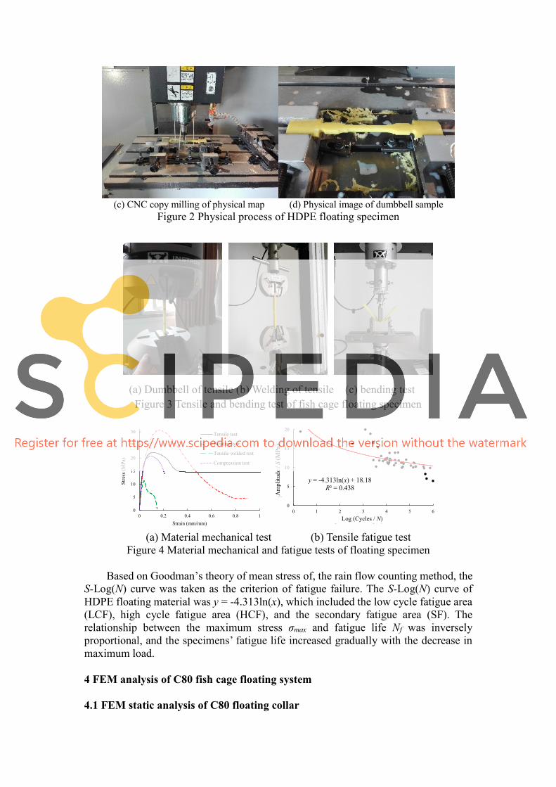
(c) CNC copy milling of physical map (d) Physical image of dumbbell sample
Figure 2 Physical process of HDPE floating specimen
(a) Dumbbell of tensile (b) Welding of tensile (c) bending test Figure 3 Tensile and bending test of fish cage floating specimen
(a) Material mechanical test (b) Tensile fatigue test
Figure 4 Material mechanical and fatigue tests of floating specimen
Based on Goodman’s theory of mean stress of, the rain flow counting method, the S-Log(N) curve was taken as the criterion of fatigue failure. The S-Log(N) curve of HDPE floating material was y = -4.313ln(x), which included the low cycle fatigue area (LCF), high cycle fatigue area (HCF), and the secondary fatigue area (SF). The relationship between the maximum stress σmax and fatigue life Nf was inversely proportional, and the specimens’ fatigue life increased gradually with the decrease in maximum load.
4 FEM analysis of C80 fish cage floating system
4.1 FEM static analysis of C80 floating collar
0
5
10
15
20
25
30
0 0.2 0.4 0.6 0.8 1
Str
ess
(MP
a)
Strain (mm/mm)
Tensile test
Bending test
Tensile welded test
Compression test
y = -4.313ln(x) + 18.18
R² = 0.438
0
5
10
15
20
0 1 2 3 4 5 6
最大应力
-0
Max
imu
m s
tres
s-0
/MP
a
Log(疲劳次数) Log(Cycles)Log (Cycles / N)
Am
pli
tud
e /
S(M
Pa)
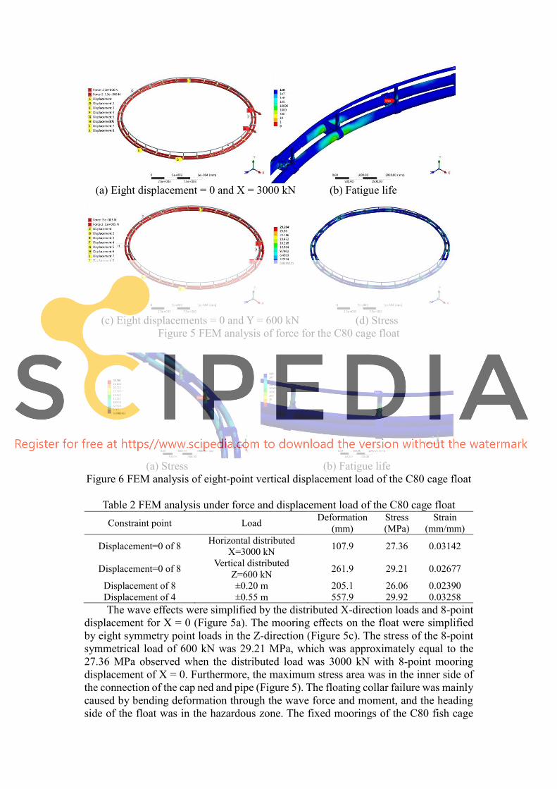
(a) Eight displacement = 0 and X = 3000 kN (b) Fatigue life
(c) Eight displacements = 0 and Y = 600 kN (d) Stress
Figure 5 FEM analysis of force for the C80 cage float
(a) Stress (b) Fatigue life
Figure 6 FEM analysis of eight-point vertical displacement load of the C80 cage float
Table 2 FEM analysis under force and displacement load of the C80 cage float Constraint point Load
Deformation
(mm) Stress
(MPa) Strain
(mm/mm)
Displacement=0 of 8 Horizontal distributed
X=3000 kN 107.9 27.36 0.03142
Displacement=0 of 8 Vertical distributed
Z=600 kN 261.9 29.21 0.02677
Displacement of 8 ±0.20 m 205.1 26.06 0.02390
Displacement of 4 ±0.55 m 557.9 29.92 0.03258
The wave effects were simplified by the distributed X-direction loads and 8-point displacement for X = 0 (Figure 5a). The mooring effects on the float were simplified by eight symmetry point loads in the Z-direction (Figure 5c). The stress of the 8-point symmetrical load of 600 kN was 29.21 MPa, which was approximately equal to the 27.36 MPa observed when the distributed load was 3000 kN with 8-point mooring displacement of X = 0. Furthermore, the maximum stress area was in the inner side of the connection of the cap ned and pipe (Figure 5). The floating collar failure was mainly caused by bending deformation through the wave force and moment, and the heading side of the float was in the hazardous zone. The fixed moorings of the C80 fish cage
had eight points, and the distributed loads in the Z vertical direction were 600 kN or in the X-horizontal direction were 3000 kN, when the floating collar initiated bending failure. Thus, the loads in the Z-vertical direction caused five times more damage than the X-horizontal direction loads.
The displacement constraint types were applied based on the floating modal shapes of Equation (1)-(2). The wave torsion load of 1.1 m was the guardrail critical point failure value (Figure 11), while 5 m was the floating pipe critical point failure value (Figure 7). The guardrail was destroyed earlier than the main floating pipe. Torsional or sheared loads caused damage more easily than the bending and tensile loads to the floating collar. The failure zone was mainly in the connections or weldings of the cap, floating pipe, and guardrail.
The mechanical analysis of fish cages mainly involves high cycle fatigue, and stress fatigue and elastic strain play important roles. The fatigue failure processes of the float mainly include three stages: the HDPE floating collar has initial cracks, and the cracks increase due to the application loads. The ability to tolerate applied loads continues to deteriorate until failure occurs. According to the Basquin nominal stress: σa = σf’(2Nf)b (8) where σf’ is the fatigue strength coefficient, Nf is the cycle number when the fatigue fracture is under a constant amplitude load, and b is the fatigue strength index. Based on the notch effect of the cage float welding structure, the relationship between the peak stress σp and net area nominal stress σn is: Kc = σp / σn (9) where Kc is the stress concentration factor of the section. The σn and Kc are used as the control parameters of the fatigue life. For the HDPE S-Log(N) curve and the components of cage float, if the stress concentration coefficient Kc and load spectrum are the same, then the service life is equal. Therefore, high and low cycle fatigues appear on the floating collar in different areas. As shown in Fig. 9–11, high cycle fatigue occurs when the working stress is much lower than the elastic limit of the HDPE material, and the stress cycle is 106–108. Low cycle fatigue occurs when the stress is close to the yield limit of the floating material, and the stress cycle is < 106 under the condition of high strain.
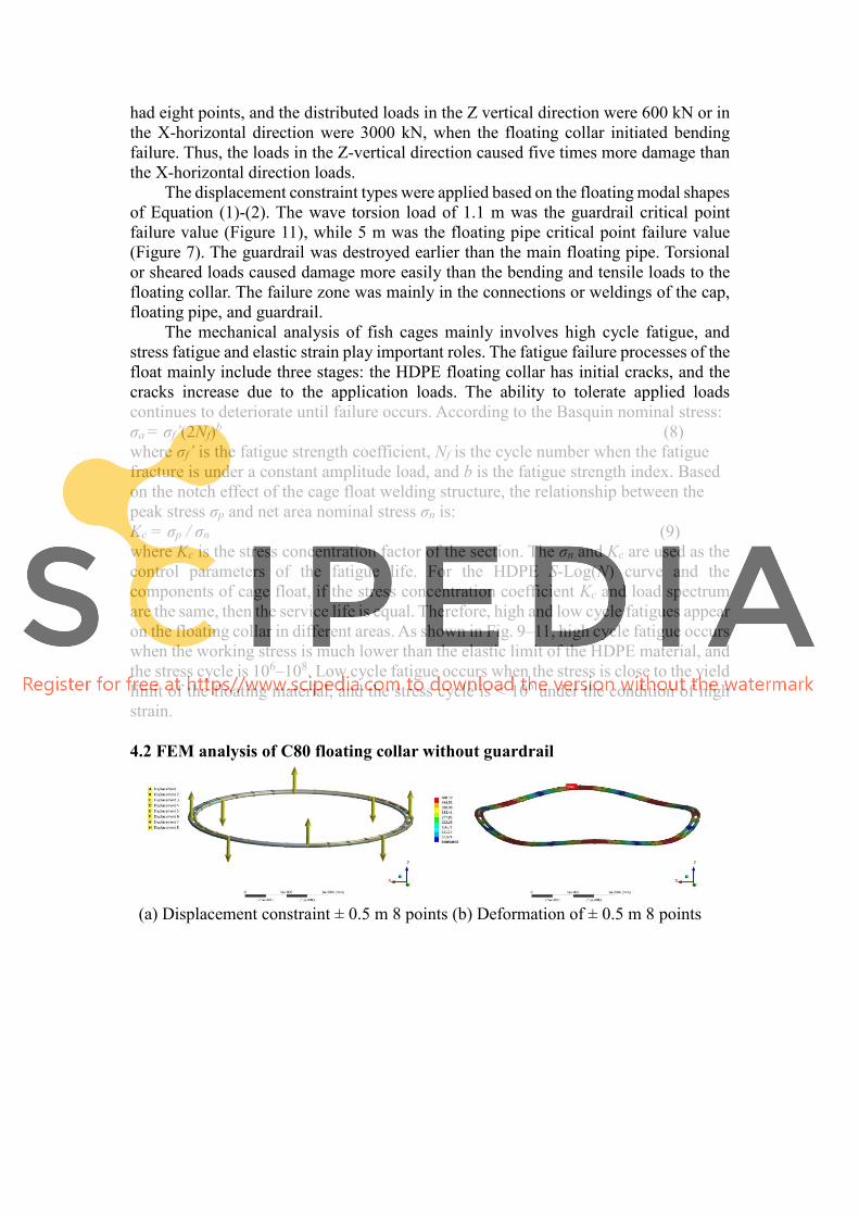
4.2 FEM analysis of C80 floating collar without guardrail
(a) Displacement constraint ± 0.5 m 8 points (b) Deformation of ± 0.5 m 8 points
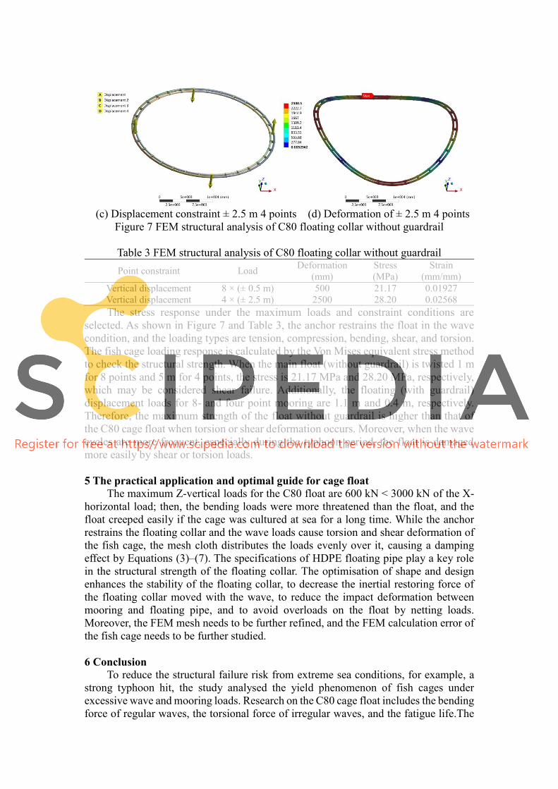
(c) Displacement constraint ± 2.5 m 4 points (d) Deformation of ± 2.5 m 4 points
Figure 7 FEM structural analysis of C80 floating collar without guardrail
Table 3 FEM structural analysis of C80 floating collar without guardrail Point constraint Load
Deformation
(mm) Stress
(MPa) Strain
(mm/mm) Vertical displacement 8 × (± 0.5 m) 500 21.17 0.01927
Vertical displacement 4 × (± 2.5 m) 2500 28.20 0.02568
The stress response under the maximum loads and constraint conditions are selected. As shown in Figure 7 and Table 3, the anchor restrains the float in the wave condition, and the loading types are tension, compression, bending, shear, and torsion. The fish cage loading response is calculated by the Von Mises equivalent stress method to check the structural strength. When the main float (without guardrail) is twisted 1 m for 8 points and 5 m for 4 points, the stress is 21.17 MPa and 28.20 MPa, respectively, which may be considered shear failure. Additionally, the floating (with guardrail) displacement loads for 8- and four point mooring are 1.1 m and 0.4 m, respectively. Therefore, the maximum strength of the float without guardrail is higher than that of the C80 cage float when torsion or shear deformation occurs. Moreover, when the wave cycles are more frequent, especially during the typhoon period, the float is damaged more easily by shear or torsion loads.
5 The practical application and optimal guide for cage float The maximum Z-vertical loads for the C80 float are 600 kN < 3000 kN of the X-
horizontal load; then, the bending loads were more threatened than the float, and the float creeped easily if the cage was cultured at sea for a long time. While the anchor restrains the floating collar and the wave loads cause torsion and shear deformation of the fish cage, the mesh cloth distributes the loads evenly over it, causing a damping effect by Equations (3)–(7). The specifications of HDPE floating pipe play a key role in the structural strength of the floating collar. The optimisation of shape and design enhances the stability of the floating collar, to decrease the inertial restoring force of the floating collar moved with the wave, to reduce the impact deformation between mooring and floating pipe, and to avoid overloads on the float by netting loads. Moreover, the FEM mesh needs to be further refined, and the FEM calculation error of the fish cage needs to be further studied.
6 Conclusion
To reduce the structural failure risk from extreme sea conditions, for example, a strong typhoon hit, the study analysed the yield phenomenon of fish cages under excessive wave and mooring loads. Research on the C80 cage float includes the bending force of regular waves, the torsional force of irregular waves, and the fatigue life.The
hydrodynamic, tensile and bending tests of HDPE cage float were performed.
The cage float can be damaged more easily when torsion or shear deformation occurs. When the cage float is twisted by 1 m for the 8-point type and 5 m for the four point type, the float is sheared. When the fixed mooring is of the eight-point type and the distributed load in the Z-vertical direction is 600 kN, or the X-horizontal direction component is 3000 kN, the floating collar may be bent; that is, the load in the Z-vertical direction does five times more damage than the load type in the X-horizontal direction. The critical points of the cage guardrail and main floating pipe may reach the yield stress when the wave height is 1.1 m and 5 m, respectively, meaning that the guardrail is destroyed before the floating pipe.
The mechanical performance test and FEM analysis were adopted to evaluate the loading response on the wave condition of the C80 fish cage, which is used to check the ultimate strength and fatigue life. The main components of stress are mainly concentrated in the floating welding areas, mooring points, and structural connection edges. Increasing the number of mooring points and cap neds can improve the ultimate bearing capacity and fatigue reliability of the floating collar. The results provide guidelines for the optimised structural design of fish cages under extreme or long-term wave conditions.
Reference
Bi C. W., Zhao Y. P., Sun X. X., Zhang Y., Guo Z. X., Wang B. and Dong G. H., 2020. An efficient artificial neural network model to predict the structural failure of high-density polyethylene offshore net cages in typhoon waves. Ocean Engineering, 196: 106793. Chu, Y. I., Wang, C. M., Park, J. C. and Lader, P. F., 2020. Review of cage and containment tank designs for offshore fish farming. Aquaculture, 519: 734928. Guo, Y. C., Mohapatra, S. C. and Soares, C. G., 2020. Review of developments in porous membranes and net-type structures for breakwaters and fish cages. Ocean Engineering, 200: 107027. Gansel, L. C., Oppedal, F., Birkevold, J. and Tuene, S.A., 2018. Drag forces and deformation of aquaculture cages—full-scale towing tests in the field. Aquacultural Engineering, 81: 46–56. Huang, X. H., Liu, H. Y., Hu, Y., Yuan, T. P., Tao, Q. Y., Wang, S. M. and Liu, Z. X., 2020. Hydrodynamic Performance of a Semi-submersible Offshore Fish Farm with a Single Point Mooring System in Pure Waves and Current. Aquacultural Engineering, 90: 102075. Huang, X. H., Liu, H. Y., Hu Y., Tao, Q. Y., Wang, S. M. and Yuan, T. P., 2018.
Deformation simulation and structural improvement design for floating collar of deep-
water aquaculture net cage. Transactions of the Chinese Society of Agricultural
Engineering, 34(15): 44–49. (in Chinese with English abstract)
Liu, H. Y., Hu, Y., Huang, X. H., Yuan, T. P., Wang, S. M., Chen, M. Q. and Guo, G. X., 2020. Failure and fatigue analysis of floating structure of offshore cage. Transactions of the Chinese Society of Agricultural Engineering, 36(3): 46–54. (in Chinese with English abstract) Liu, H. Y., Huang, X. H., Wang, S. M., Hu, Y., Yuan, T. P. and Guo, G. X., 2019.
Evaluation of the structural strength and failure for floating frame of a single-point
mooring fish cage based on finite element method. Aquacultural Engineering, 85: 32–48.
Liu, H. Y., Wang, S. M., Huang, X. H., Tao, Q. Y., Hu, Y., Guo, G. X. and Song, L.
M., 2017. Mechanical properties analysis and optimization of deep-water net cage
guardrail. Transactions of the Chinese Society of Agricultural Engineering, 33(4): 248–257. (in Chinese with English abstract)
Wan, R., Guan, Q. L., Li, Z. G., Hu, F. X., Dong, S. C. and You, X. X., 2020. Study on hydrodynamic performance of a set-net in current based on numerical simulation and physical model test. Ocean Engineering, 195: 106660. Wang, L. Q., Wei, Z.L., Yao, S. M., Guan, Y. and Li, S. K., 2018. Sealing performance and optimization of a subsea pipeline mechanical connector. Chinese Journal of Mechanical Engineering, 31(1): 142-155. Xu, Z. J. and Qin, H. D., 2020. Fluid-structure interactions of cage based aquaculture: From structures to organisms. Ocean Engineering, 217: 107961. Yu, Z. L., Amdahl, J., Kristiansen, D. and Bore, P. T., 2019. Numerical analysis of local and global responses of an offshore fish farm subjected to ship impacts. Ocean Engineering, 194: 106653.1–106653.17.
Acknowledgement The research was supported by the Hainan Provincial Joint Project of Sanya Yazhou Bay Science and Technology City, Grant No: 520LH039; National Natural Science Foundation of China, Grant No: 31902424; National Key R&D Program of China, Grant No: 2019YFD0900903.