Embed Size (px)
Citation preview

I Ü I Ä
i.·«
pkfuï I Wil
up
»ir i
OF THE CARBONACEOUS MESOPHAS FORMED IN THE HEAT TREATMENTfSL· GRAPHITIZABLE ORGANIC MATERIALS
ΜΤΤ'ψη»'« 'If
Neither the Commission of the European Communities contractors nor any person acting on their behalf :
Ι:^Ο·"Ι8ΙΙ·Λ ! fií(iíliíii: lÜ&Hu ?ΠΙ!Λ·Ι is'ÏSÎr H I ι J r ' ('Sí !>Βι> ^^ÄP&TT^^ ι *'*r- ij»wWi¿k¿líWil' make any warranty or representation, express or implied, with respect to the accuracy, completeness, or usefulness of the information contained in this document, or tha t the use of any information, apparatus, method or process disclosed in this document may not infringe privately owned r ights ; or
assume any liability with respect to the use of, or for damages resulting from the use of any information, apparatus, method or process disclosed in this document.
,, its
1 This report is on sale a t the addresses listed on cover page 4
in . lá Fl. 3.
When ordering, please quote the EUR number and the title, which are indicated on the cover of each report.
Printed by L. Vanmelle, Ghent
Luxembourg, April 1971
is document was reproduced on the basis of the best available

EUR 4627 e THE MICROGRAPHY OF THE CARBONACEOUS MESOPHASE FORMED IN THE HEAT TREATMENT OF GRAPHITIZABLE ORGANIC MATERIALS by J. DUBOIS, C. AGACE and J.L. WHITE Commission of the European Communities Joint Nuclear Research Centre Petten Establishment (Netherlands) Luxembourg, April 1971 — 26 Pages — 16 Figures — B.Fr. 40.—
Observations by polarized light of the microstructures formed during the heat treatment of materials used to fabricate graphitic artifacts have directed attention to the short range of temperature during which the carbonizing liquid exists as a liquid crystal termed the carbonaceous mesophase. The poor polishing characteristics of the unhardened mesophase required modifications to the preparation methods used for carbons and graphites. A temperature-gradient heat-treatment technique was employed to obtain specimens representative of the various mesophase microstructures developed in the
EUR 4627 e THE MICROGRAPHY OF THE CARBONACEOUS MESOPHASE FORMED IN THE HEAT TREATMENT OF GRAPHITIZABLE ORGANIC MATERIALS by J. DUBOIS, C. AGACE and J.L. WHITE
Commission of the European Communities Joint Nuclear Research Centre Petten Establishment (Netherlands) Luxembourg, April 1971 — 26 Pages — 16 Figures — B.Fr. 40.—
Observations by polarized light of the microstructures formed during the heat treatment of materials used to fabricate graphitic artifacts have directed attention to the short range of temperature during which the carbonizing liquid exists as a liquid crystal termed the carbonaceous mesophase. The poor polishing characteristics of the unhardened mesophase required modifications to the preparation methods used for carbons and graphites. A temperature-gradient heat-treatment technique was employed to obtain specimens representative of the various mesophase microstructures developed in the

short plastic range. Three mechanisms—the mesophase transformation itself, the coalescence of the initial spherules to bulk mesophase, and the plastic flow before hardening—act to establish the principal features of the lamelliform morphology of a graphitizable coke. Fine insoluble particles are segregated by the mesophase transformation, and the effect of larger graphitic particles is to align the mesophase layers parallel to the layer planes of the substrate. Upon heat treatment of the hardened mesophase to graphitizing temperatures, shrinkage cracking and fine-scale mechanisms of fold-sharpening and poly-gonization take place to yield the final microstructure of the graphitic product.
short plastic range. Three mechanisms—the mesophase transformation itself, the coalescence of the initial spherules to bulk mesophase, and the plastic flow before hardening—act to establish the principal features of the lamelliform morphology of a graphitizable coke. Fine insoluble particles are segregated by the mesophase transformation, and the effect of larger graphitic particles is to align the mesophase layers parallel to the layer planes of the substrate. Upon heat treatment of the hardened mesophase to graphitizing temperatures, shrinkage cracking and fine-scale mechanisms of fold-sharpening and poly-gonization take place to yield the final microstructure of the graphitic product.
short plastic range. Three mechanisms—the mesophase transformation itself, the coalescence of the initial spherules to bulk mesophase, and the plastic flow before hardening—act to establish the principal features of the lamelliform morphology of a graphitizable coke. Fine insoluble particles are segregated by the mesophase transformation, and the effect of larger graphitic particles is to align the mesophase layers parallel to the layer planes of the substrate. Upon heat treatment of the hardened mesophase to graphitizing temperatures, shrinkage cracking and fine-scale mechanisms of fold-sharpening and poly-gonization take place to yield the final microstructure of the graphitic product.

EUR 4627 e
COMMISSION OF THE EUROPEAN COMMUNITIES
THE MICROGRAPHY OF THE CARBONACEOUS MESOPHASE FORMED IN THE HEAT TREATMENT
OF GRAPHITIZABLE ORGANIC MATERIALS
by
J. DUBOIS, C. AGACE and J. L. WHITE
1971
Joint Nuclear Research Centre Petten Establishment - Netherlands

ABSTRACT Observations by polarized light of the microstructures formed
during the heat treatment of materials used to fabricate graphitic artifacts have directed attention to the short range of temperature during which the carbonizing liquid exists as a liquid crystal termed the carbonaceous mesophase. The poor polishing characteristics of the unhardened mesophase required modifications to the preparation methods used for carbons and graphites. A temperature-gradient heat-treatment technique was employed to obtain specimens representative of the various mesophase microstructures developed in the short plastic range. Three mechanisms—the mesophase transformation itself, the coalescence of the initial spherules to bulk mesophase, and the plastic flow before hardening—act to establish the principal features of the lamelliform morphology of a graphitizable coke. Fine insoluble particles are segregated by the mesophase transformation, and the effect of larger graphitic particles is to align the mesophase layers parallel to the layer planes of the substrate. Upon heat treatment of the hardened mesophase to graphitizing temperatures, shrinkage cracking and fine-scale mechanisms of fold-sharpening and poly-gonization take place to yield the final microstructure of the graphitic product.
KEYWORDS
LIGHT OPTICAL SYSTEM POLARIZATION GRAPHITE CARBON CHEMICAL REACTIONS CRYSTALS PHASE DIAGRAMS COKE HEAT TREATMENTS DECOMPOSITION PYROLYSIS

ABSTRACT * )
Observations by polarized light of the microstructures formed during the pyrolysis of materials used tó fabricate graphitic artifacts have directed attention to the narrow range of temperature during which the carbonizing liquid exists as a liquid crystal called the carbonaceous mesophase. The poor polishing characteristics of the unhardened mesophase required modifications to the preparation methods used for carbons and graphites. A temperature gradient heat-treatment technique was employed to obtain specimens representative of the various mesophase morphologies developed in the short plastic range. Three mechanisms - the mesophase transformation itself, the coalescence of the initial spherules to bulk mesophase, and the plastic flow before hardening - act to establish the principal features of the lamelliform morphology of a graphitizable coke. Fine insoluble particles are segregated by the mesophase transformation, and the effect of graphitic substrate particles is to align the mesophase layers parallel to the layer planes of the substrate. Upon heat treatment of the hardened mesophase to graphitizing temperatures, shrinkage-cracking and fine-scale mechanisms of fold-sharpening and polygonization take place to yield the final microstructure of the graphitic product.
INTRODUCTION
The techniques of optical micrography applied to commercial organic materials at various stages of carbonization and graphitization have been fruitful in recent years in shedding light on the mechanisms acting to make a material graphitizable. [1-7] Although the chemical reactions involved in liquids-phase pyrolysis are complex, [8-11] the problems of understanding the formation of the morphology have been simplified by the recognition, originally by Brooks and Taylor, [1,2] of the significant role of the mesophase transformation which takes place in graphitizable organic materials during carbonization between 400 and 500°C. The carbonaceous mesophase is the result of a liquid-state structural transformation in which the large planar aromatic molecules produced by the pyrolysis reactions are aligned parallel to form an anisotropic liquid crystal.
Although the carbonaceous mesophase behaves as a solid material at room temperature, the properties vary over a wide range depending on the heat treatment. Thus a complete study of the development of microstructure in a graphitizable material during pyrolysis from the temperature of the mesophase transformation to 3000°C [6] encounters a number of problems of micrographie preparation. At room temperature, freshly formed mesophase which has not been heat-treated beyond the plastic liquid-crystalline condition is friable and readily crumbles under stress. Furthermore pyrolysis in the plastic region usually
leads to the nucleation, growth, and percolation of gas bubbles, and the mesophase is locally subjected to extensive plastic deformation; these strains can produce a fibrous folded microstructure, which requires high magnifications for satisfactory resolution. After hardening by continued pyrolysis, anisotropic shrinkage effects take place, leading to the formation of lamellar cracks in a wide range of sizes. Upon heat treatment to graphitizing temperatures, the mesophase fossils soften as the graphite crystallinity is developed, and magnifications near the upper limit of optical techniques are necessary to resolve the microstructural processes of fold-sharpening and polygonization.
When micrographie methods are applied to the materials and processes employed in the fabrication of commercial graphitic products, the problem of hard particles in a soft matrix is encountered in two forms. Firstly, most binder and imprégnant pitches contain, or develop in the early stages of pyrolysis, [2] appreciable quantities of hard particles which resemble carbon black in size and shape. [12] Although these particles are insoluble in the carbonaceous mesophase, they act to modify the micro-structure as well as to increase the difficulties of polishing. Secondly, conventional graphite manufacture involves the fabrication of binder-filler artifacts in which the filler coke remains in a more advanced state of pyrolysis than the binder or imprégnant until the later stages of heat treatment are reached. Accordingly the problem of polishing relief usually enters to complicate the micrographie preparation of the pregraphitic artifacts.
One purpose of the present paper is to describe how the foregoing problems have been attacked using conventional metallographic techniques but with special care in the later stages of polishing. In some cases it is evident that more complicated methods, such as low-temperature polishing or cathodic etching, [13] would be useful in making further improvements in preparation. However relatively simple techniques have been adequate to reveal the principal features of the microstructure at the magnifications accessible to optical observation, and the degree of success attained is illustrated by photomicrographs and structural sketches of specimens chosen to represent the micrographie problems outlined above.
The ultimate objective of the micrographie studies is to contribute to a scientific basis for the control of the morphology of the carbons and graphites produced by liquid-phase pyrolysis. Accordingly a second purpose of this parper is to present further results to add emphasis and detail to the point [4,6,14] that the principal features of the morphology are established by the molecular alignment, coalescence, and flow which occur in the carbonaceous mesophase during the short interval of time and temperature in which it is liquid or plastic. The effects of further heat treatment of the hardened, or coked, mesophase comprise microstructural modifications which are minor by comparison with those resulting directly from the mesophase transformation.
*) M a n u s c r i p t r e c e i v e d on J a n u a r y I 9 , 1970

- 4 -
MATERIALS PREPARATION AND PYROLYSIS
The methods of micrographie preparation described here have been found suitable for various types of graphitizable materials used in the fabrication of graphitic artifacts, including coal-tar pitches used as binder or imprégnant and petroleum coker feedstocks used in the manufacture of filler coke. However the morphologies formed by the heat treatment of these commercial materials or their binder-filler artifacts have resisted micrographie analysis not only because of polishing difficulties but also because the effects of insoluble particles, substrate grains (i.e., filler cokes), bubble percolation,^ and shrinkage-cracking combine to produce complex microstructures whose details lie near or beyond the limit of resolution of ordinary optical techniques. Accordingly we have sought to simplify the analysis experimentally by beginning with the relatively simple mesophase morphologies formed in selected coal-tar pitches from which the insoluble particles have been removed by solvent extraction.[5,6] Proceeding from this base, subsequent experiments were designed to investigate the specific microstructural modifications resulting from the presence of insoluble particles or substrate grains or from the use of different starting materials.
The solvent-extraction process employed to remove the insoluble particles from coal-tar pitch followed the procedure of Hooker and Norman.[12] The extraction was made with tetrahydrofuran at 60°C. After cooling to room temperature, the solution was filtered through successively finer sintered-glass filters, the final filter being specified as two microns in pore size. Although electron micrographs reveal that most of the hard insoluble particles in a typical
binder pitch are less than two microns in diameter,[12] their ready agglomeration with the high-molecular-weight components which are also insoluble in tetrahydrofuran accounts for their effective removal by the two-micron filter. After filtration, the tetrahydrofuran was removed by evaporation from large pans in a vacuum oven.
The effects of substrate grains on the formation of the mesophase morphology were observed in specimens prepared by adding sizes particles of calcined petroleum coke or natural graphite flakes to extracted pitch. Similar observations were made on some specimens consisting of extracted pitch containing four types of carbon-coated spheres representing the pyrolytic carbon structures made in the fluidized bed, viz., laminar, isotropic, granular, and columnar. As-received samples of coal-tar pitch proved satisfactory for observations of the effects of insoluble particles on the development of microstructure; an impregnating pitch was selected for the initial studies in view of its relatively low content of insoluble particles.
Although quantitative kinetic information on the mesophase transformation and the subsequent processes of coalescence, bubble percolation, and hardening are presently quite limited in scope, it is clear that the transition and the resulting structures are sensitive to temperature and the rate of heating for both coal-tar pitches [2,4,6,15] and petroleum coker feedstocks.[16,17] Therefore a temperature-gradient heat-treatment technique was developed to obtain series of specimens representative of slightly varying degrees of heat treatment. A schematic diagram of a temperature gradient furnace designed for this purpose is shown in Figure 1.
The temperature-gradient is maintained in a steel bar
OLASS CELL INLET FOR INERT CAS
CONTAINMENT BOX FOR THERMAL INSULATION
Fig. 1 Schematic diagram of a temperature-gradient furnace for the liquid-phase pyrolysis of organic materials.
into which are inserted pyrolysis tubes made of glass or metal. Copper sleeves are employed to improve the temperature uniformity in each cell. Two rows of cells have been used in experiments aimed at comparing the structures found in different starting materials or in the presence of various substrate particles. A glass plate on the top of the cell compartment permits qualitative observations of gas evolution and mesophase hardening.
In the usual operation, the desired temperature gradient is first established by adjustment of the power in the internal end-heater. About six hours are required to attain a steady-state condition. Then the entire bar is increased in temperature by applying a programmed power input to the main side-heaters. Gentle and uniform heating is often necessary, at rates of the order of 10°C/hr or less, in order to pass through the mesophase transformation and the subsequent plastic range of the mesophase without excessive foaming by bubble percolation.
After the mesophase has hardened, special care in heat treatment is no longer necessary. In the present work, several types of graphite resistance furnace have been used for heat treatments above 600°C. The specimens of hardened mesophase were heat-treated in graphite cups which contained thermocouple wells for heat treatments to 1000°C or black-body cavities for heat treatments to higher temperatures.
MICROGRAPHIC PREPARATION
The micrographie preparation of the carbonaceous mesophase comprises the steps of impregnation and mounting, grinding, rough polishing, and final polishing. The procedures were developed from those employed in the micrographie preparation of conventional carbons and graphites [18,19] and differ appreciably only in the final steps.
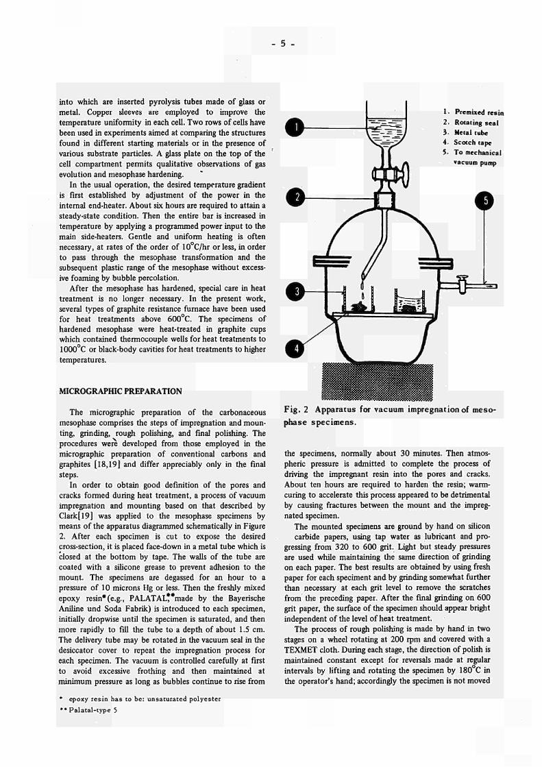
In order to obtain good definition of the pores and cracks formed during heat treatment, a process of vacuum impregnation and mounting based on that described by Clark[19] was applied to the mesophase specimens by means of the apparatus diagrammed schematically in Figure 2. After each specimen is cut to expose the deshed cross-section, it is placed face-down in a metal tube which is closed at the bottom by tape. The walls of the tube are coated with a silicone grease to prevent adhesion to the mount. The specimens are degassed for an hour to a pressure of 10 microns Hg or less. Then the freshly mixed epoxy resin*(e.g., PALATAL**made by the Bayerische Aniline und Soda Fabrik) is introduced to each specimen, initially dropwise until the specimen is saturated, and then more rapidly to fill the tube to a depth of about 1.5 cm. The delivery tube may be rotated in the vacuum seal in the desiccator cover to repeat the impregnation process for each specimen. The vacuum is controlled carefully at first to avoid excessive frothing and then maintained at minimum pressure as long as bubbles continue to rise from
* epoxy resin has to be: unsaturated polyester ** Palatal-type 5
1 . Premixed resin 2. Rotating seal 3- Metal tube 4. Scotch tape 5· To mechanical
vacuum pump
Fig. 2 Apparatus for vacuum impregnation of mesophase specimens.
the specimens, normally about 30 minutes. Then atmospheric pressure is admitted to complete the process of driving the imprégnant resin into the pores and cracks. About ten hours are required to harden the resin·; warm-curing to accelerate this process appeared to be detrimental by causing fractures between the mount and the impregnated specimen.
The mounted specimens are ground by hand on silicon carbide papers, using tap water as lubricant and pro
gressing from 320 to 600 grit. Light but steady pressures are used while mamtaining the same direction of grinding on each paper. The best results are obtained by using fresh paper for each speciment and by grinding somewhat further than necessary at each grit level to remove the scratches from the preceding paper. After the final grinding on 600 grit paper, the surface of the specimen should appear bright independent of the level of heat treatment.
The process of rough polishing is made by hand in two stages on a wheel rotating at 200 rpm and covered with a TEXMET cloth. During each stage, the direction of polish is maintained constant except for reversals made at regular intervals by lifting and rotating the specimen by 180 C in the operator's hand; accordingly the specimen is not moved

- 6 -
560χ crossed polarizers
mesophase sphere with section including polar diameter
pole
Fig. 3 The structure of mesophase spherules, formed by the pyrolysis of an extracted coal-tar pitch to 464°C.

- 7 -
about the wheel but is only moved laterally between the center and the periphery. In the first stage, the polishing cloth is charged with 0.3-micron alumina (Buehler ALPHA MICROPOLISH), distilled water is used as lubricant, and relatively heavy pressures are applied. The specimen is thoroughly cleaned by a water jet before undertaking the second stage in which the polishing cloth is charged with 0.05-micron alumina (Buehler GAMMA MICROPOLISH), and the technique is altered only by reducing the pressure as the polishing advances. At the conclusion of rough polishing, the characteristic mesophase microstructure should be discernible by observation with crossed polarizers, although with many fine scratches still present.
The final polishing is performed on a vibratory polisher (Buehler VIBROMET) operating in a dust-free atmosphere. The only fully satisfactory results have been obtained by use of a fresh and quite clean Selvyt MICROPOLISH cloth with distilled water as lubricant and no polishing abrasive. Care is required to adjust the vibration rate to the polishing behaviour of each specimen; if the rate is too low, the polish is ineffective, but at excessively high rates the more friable specimens can be seriously damaged. The polishing time varies with the nature of the specimen, but conditions can usually be found to complete the final polishing within an hour. When the polish is complete, the carbonaceous mesophase has a characteristic bright luster by which it is readily distinguished by the naked eye from untransformed material.
The foregoing procedure may produce appreciable relief in specimens consisting of components with a large disparity in polishing hardness. Since the mesophase structure in the immediate neighbourhood of a hard substrate is often of special interest, a modified procedure using diamond abrasive was developed to give a more planar as well as a more nearly finished surface at the conclusion of the rough polishing. An automatic polisher (Buehler POLIMET with WHIRLIMET attachment) with a nylon cloth is used with lapping oil as lubricant. The rough polish is made in two stages with 1-micron and 1/4-micron diamond powder, respectively. Light pressures and moderate speeds (e.g., 250 rpm) are used, and the polishing time in each stage is typically one hour. At the conclusion of this modified procedure for rough polishing, the rather fine scratches still remaining in the mesophase can be reduced by a brief vibratory polish on Selvyt MICRO-POLISH cloth with no polishing abrasive. The time for this final polishing is chosen for each specimen to compromise perfection of polish against the development of relief and varies depending on the disparity in hardness as well as the type of observation to be made.
MICROGRAPHIC RESULTS
The value of polarized-light micrography in studies of the mechanisms of carbonization and graphitization stems from the fact that the strong optical anisotropy character
istic of the graphite crystal [20,21] begins with the parallel alignment of the aromatic molecules to form the carbonaceous mesophase. Accordingly the polarized-light response on a polished section can be used to identify the orientations of the mesophase layers relative to the plane of section [22] as well as to distinguish the specific types of layer-stacking discontinuity. [5,6] Furthermore the sensitive-tint technique is useful in illustrating the orientational relationships which exist between the mesophase layers and various substrate materials. [1,2] The flexibility of working with both crossed and parallel polarizers, as well as with intermediate angles between the analyzer and polarizer, can be advantageously employed to emphasize particular micro-structural features, e.g., the segregation of insoluble particles during the carbonization of commercial materials.
The mesophase spherules formed in the pyrolysis of an extracted electrode pitch are illustrated at an early stage of their nucleation and growth by Figure 3. At this stage the mesophase is very fragile and crumbles when lightly pressed with a blunt probe. However in the absence of insoluble particles a satisfactory polish is readily achieved, with special delicacy required only in the final stages. It should be noted that the ultrasonic cleaning commonly employed with metals can easily destroy the freshly formed mesophase, and we have eliminated ultrasonic cleaning from our procedures regardless of the heat treatment of the mesophase.
The structural sketch, which indicates the orientations of the mesophase layers relative to the plane of section, was prepared from a series of polarized-light micrographs made at increasing angles of stage rotation. As observed with crossed polarizers, the extinction contours define the loci of points where the layers are either parallel or perpendicular to the plane of polarization of the incident light.[22] Observations by parallel polarizers or the sensitive-tint technique may be used to resolve these cases, and the structure may then be sketched by applying an overlay successively to the series of micrographs. The area of Figure 3 was chosen because two spherules have been fortuitously sectioned quite near to their polar diameters, thus revealing the layer-stacking pattern of the liquid crystal. This characteristic structure of the simple spherules formed in an extracted coal-tar pitch was first demonstrated by Brooks and Taylor [1] by applying selected-area electron diffraction to thin sections of spherules sectioned on or near to their polar diameter. The layers are aligned perpendicular to the polar diameter but curve to meet the interface with the isotropic matrix at a high angle. The poles constitute anomalous regions, but this is reflected in little if any departure of the droplet from spherical geometry.
As the pyrolysis of the extracted pitch proceeds to higher temperatures, the mesophase spherules grow rapidly and sink to the bottom of the container owing to their density being higher than that of the isotropic matrix. [4,7,15] When the spherules meet, coalescence may occur, leading ultimately to the bulk mesophase illustrated by Figure 4. The large coalesced drops, as well as the bulk

- 8
a) lOOx, crossed polar izers , b) 82Qx, crossed polarizers
mesophase, display complex arrays of polarized-light extinction contours. The lamelliform morphologies corresponding to these arrays have been analyzed in previous papers [5,6 ] in which the nodes and crosses are classified as four specific types of linear discontinuity in the layer stacking.
As suggested by Figure 4a, there appears to be an upper limit, for a given coal-tar pitch and heat treatment, to the size of the droplets found with the simple structure of the mesophase spherule. Figure 4b illustrates spherules and droplets of varying complexity caught in the act of coalescence. These micrographs also show some small islands of isotropic material, which could comprise untransformed pitch trapped geometrically by the coalescence mechanism. However these isotropic islands are often found deep within the bulk mesophase. Since Honda et al. [7] have shown that pyrolytic reactions continue in the mesophase after transformation it seems likely that many of these islands have been formed by the rejection of reaction products whose molecules are incompatible with
the carbonaceous mesophase. In order to gain further insight into the coalescence
process, the structural sketch of Figure 5 was prepared. As indicated by the radii of curvature of the mesophase-matrix interface, the two coalescence processes shown here are in two quite different states of assimilation. The mechanism of coalescence appears to be a simple process of interleaving of the mesophase layers. The fact that many spherules resist coalescence despite their contiguity can reasonably be attributed to the layers in the adjacent bodies not being sufficiently parallel for initiation of the interleaving mechanism.
The viscosity of the mesophase formed in the pyrolysis of the extracted pitch is sufficiently low to permit appreciable structural rearrangement by flow during and after coalescence. The end result of this rearrangement would presumably be the equilibrium defect-free structure of the simple spherule (cf. Figure 3), provided that the rearrangement process is not interrupted by hardening or complicated by new coalescence processes. The excess
F ig . 4 The coa lescence of spherules to form bulk mesophase in an extracted impregnating pitch pyro-lyzed to 465°C.

- ? -
Indicates mesophase regions which are optically isotropic.
crossed polarizers. 500 χ
50 microns
Fig . 5 Photomicrograph and structural sketch illustrating the coalescence process in an extracted coal-tar pitch.

10
pyrolyzed to 430°C
200x
2° off crossed polarizers
pyrolyzed to 436°C
200x
2° off crossed polarizers
pyrolyzed to 538°C
200x
2° off crossed polarizers
'M&
Fig'. 6 Coalescence with limited structural rearrangement, as observed in the pyrolysis of a resin.

11
energies associated with the mesophase-matrix interface, the layer-stacking defects, and the layer-folding appear to constitute the driving forces for the rearrangement process, and the intensity of these forces will dissipate rapidly as the droplet grows and the density of defects and folds is decreased. The extent of rearrangement in response to these forces will depend on the viscosity and its rate of increase as the mesophase pyrolysis reactions continue. Although quantitative data for these properties do not exist, it is clear that there is a droplet size, dependent on the specific properties of the particular mesophase as well as the schedule of heat treatment, at which rearrangement becomes^ too sluggish to keep up with the structural complications of further coalescence, and the various defect structures will thus be locked into the larger droplets and bulk mesophase.
Observations of a variety of extracted coal-tar pitches revealed essentially the same general behavior of nucleation, growth, coalescence and structural rearrangement of the mesophase, although there were some minor differences in the transformation temperatures. However when attention was directed -to other types of graphitizable organic materials, some rather different microstructures were found; the first case was the hydrocarbon resin illustrated in Figure 6. In the early stages spherules were formed as in the case of .the coal-tar pitches, but these spherules appear to nucleate more rapidly in comparison with their growth and coalescence, leading to a dense array of small spherules. Coalescence occurs, but in a stringy manner, and with less rearrangement of the coalesced microstructure. Strings or layers of spherules extend through the isotropic matrix, trapping relatively large islands of untransformed material, and thus producing a strong tendency to foaming during continued pyrolysis. Observations at higher magnification show that the polarized-light extinction contours display nodes and crosses and behave in the same manner as in the case of the coarse-structured mesophase formed from the coal-tar pitches.
The phenomenon of stringy coalescence may also be observed in petroleum coker feedstocks; see Figure 7. Such feedstocks range appreciably in chemical content, depending upon the crude petroleum source as well as the operating pattern of the refinery in which they are produced, but in general they contain lower amounts of aromatic compounds and larger amounts of heteroatoms than the coal-tar pitches. [17] The mesophase transformation illustrated in Figure 7 for a relatively low-sulfur feedstock begins,by nucleation and stringy coalescence to form a bulk mesophase with a fine structure of extinction contours.* The fine-structured coalescence leads to a randomized microstructure which appears by qualitative microscopic observation to be isotropic on a scale of the order of 100 microns. However the mesophase formed at a later stage of pyrolysis undergoes coalescence and rearrangement to give a coarse structure of extinction contours. In some cases this coarse-structured mesophase appears to have filled the pores formed earlier in the stiffer,
more finely structured mesophase. Thus is formed a 'two-phase' microstructure, which persists through the hardening process. t
The possibility of producing a randomly oriented and fine-structured coke of reasonable graphitizability is promising for various modern applications of graphitic materials.[23] For example, extensive studies of the effects of irradiation on model structures of pyrolytic carbon indicate that microstructures which are highly graphitic and isotropic should offer exceptional dimensional stability under the operating conditions of power reactors of advanced design. [24] Recent observations by Pitner [25] on various grades of a commercial graphite possessing these characteristics (POCO graphite) confirm this point.
Studies of the relationship of the graphitizability to the chemistry of the starting materials are relevant to the question of preparing a fine-structured, isotropic, and graphitizable coke. The results obtained by Ihnatowicz et al. [4] and by Kipling et al. [26] on the effects of oxygen and sulfur, respectively, in the starting materials are particularly useful because these investigators related the graphitizability to the behavior of the plastic mesophase. These heteroatoms had similar effects in increasing the viscosity and decreasing the plastic range of the mesophase. Concurrently the graphitizability was reduced and could be completely suppressed by sufficiently high concentrations of oxygen or sulfur in the starting materials. These effects were non-linear; modest amounts of the heteroatoms had little effect on the characteristics of the mesophase, but when a threshold concentration level was exceeded, e.g., five wt.- % sulfur added to polyvinyl chloride, [26] the fluidity of the mesophase as well as the temperatures defining the limits of its plastic range dropped sharply. In the case of sulfur, Kipling et al. [26] attributed these effects to cross-linking reactions induced in the early pre-mesophase stages of pyrolysis.
An example of a randomly oriented, fine-structured coke produced by pyrolysis of a petroleum asphalt is given in Figure 8. The asphalt was selected to sulfur content (4.4 wt.-% in order to obtain the mesophase transformation but with little rearrangement after coalescence.
It should be noted that these chemical effects on the properties of the mesophase are not necessarily limited to heteroatoms such as oxygen or sulfur, which may be present in the starting materials, but apparently may also be achieved by varying the chemical structure of the starting materials to cause different sequences of pyrolysis reaction to be followed. Smith and Harper [27] found that, while
* It would be convenient but misleading to describe the lamelliform microstructure of the coalesced bulk mesophase in terms of grain size, e.g., to describe in simple terms the difference between the fine structure formed initially in the coker feedstock (Figures 7 and 8) and the coarse structure usually found in a pitch-base mesophase immediately after coalescence. The apparent grain boundaries are in fact polarized-light extinction contours, and the region between any pair of contours consists, in the simplest and most common cases, of curved layers whose orientation on the plan of section varies by 90 from one contour to the next.

- 12 -
pyrolyzed to 452°C
mesophase transformation and stringy coalescence in progress
200x 3° off crossed polarizers
pyrolized to 468°C
'two-phase' structure forming during later stages of mesophase transformation
180x crossed polarizers
pyrolyzed to 6l7°C
'two-phase' structure in hard-coked specimen
400x 2° off crossed polarizers
Fig. 7 Stringy coalescence and the formation of a two-phase microstructure in a petroleum coker feedstock specified to contain 0.6% to 1.0% sulfur.

- 1 3 -
a) Coa lescence in progress , pyrolyzed to 432°C, b) After hardening by continued pyrolysis to 586°C,
400x, crossed polarizers. 800x, crossed polarizers.
F ig . 8 The coa lescence of fine mesophase spherules in a petroleum asphal t (4.4 wt.—% sulfur) se lec ted to produce a randomly oriented, fine-structured coke .
isotruxene is graphitizable, its isomer truxene is not, and that truxene may be mixed with isotruxene to vary the level of graphitizability. The two-phase microstructure of Figure 7 also suggests the existence of two or more sequences of pyrolytic reactions and products in the same specimen, leading to a structural segregation during the mesophase transformation. It is worth noting that the manner of development of this two-phase microstructure is consistent with the observations of Ihnatowicz et al.[4] who found that materials of lower graphitizability transform to mesophase at lower temperatures.
Continued pyrolysis of the freshly formed mesophase causes further dehydrogenation reactions. Unless the mesophase has hardened immediately after coalescence, the nucleation, growth, and percolation of bubbles produces extensive flow or plastic deformation which constitutes another important mechanism of structural refinement. Figure 9 illustrates the refinement produced by bubble percolation in an extracted coal-tar pitch whose mesophase displays the usual coarse microstructure immediately after
coalescence. Previous work [6] has shown that the regions displaying a fibrous array of polarized-light extinction contours are comprised of folded lammelae with a strong preferred orientation of layers parallel to the extinction contours. The mosaic regions apparently result from a different plane of section through the same type of folded and oriented microstructure. The density of layer-stacking defects, corresponding to the nodes and crosses in the extinction contours, has increased by several orders of magnitude, but the structure of the defects, as inferred from their response to rotation of the plane of polarization of the incident light, is essentially the same as found in the coarse-structured mesophase.
As pyrolysis proceeds, the viscosity of the mesophase increases until it is no longer plastically responsive to the stresses of bubble percolation. The complex arrays of folded lamellae and linear discontinuities in layer stacking are then frozen into the mesophase microstructure, and the further effects of heat treatment comprise principally fine-scale modifications, namely, shrinkage cracking or

- 14 -
/ΧΜ'
fibrous and mosaic structures at low magnification
200x
crossed polarizers
fibrous structure from upper right-hand region of micrograph a
1300x, oil immersion
crossed polarizers
mosaic structure from lower right-hand region of micrograph a
1300x, oil immersion
crossed polarizers
Fig. 9 The refirement of lamelliform microstructure by bubble percolation in an extracted coal-tar pitch pyrolyzed to 515°C.

- 15
900χ, sens i t ive tint
counter-rotating X5j§s§£Í^-\.-= node
optically isotropic region 50^
Fig . 10 Shrinkage cracking in an extracted coal-tar pitch heat-treated to 800°C.

- 16
a) Heat-treated to 1400°C
575x, Oil immersion sensitive tint.
b) Heattreated to 3000°C
2200x, Oil immersion, sensitive tint.
Fig. 11 Fold-sharpening and polygonization in an extracted coal-tar pitch heat-treated to calcining and graphitizing temperature.
fissuring, the sharpening of folded regions to form linear boundaries, and polygonization as the final step of graphiti-zation. Although the hardened mesophase is much less fragile in respect to polishing processes, some care is still required in the final steps of preparation because high magnifications are necessary to resolve the microstructural modifications as the temperature of heat treatment is increased from 500° to 3000°C.
Shrinkage-cracking is the first effect observed on heat-treating the hardened mesophase. Lenticular cracks, generally running parallel to the mesophase layers, open up as the result of a greater shrinkage perpendicular to the layers than parallel to them. The cracks appear first in coarse-structured regions and at folds in the mesophase layers; for example, shrinkage-cracking is extensive in a coarse mesophase from extracted pitch pyrolyzed to 620°C, [6] but no cracks are microscopically observable in the fine structured mesophase heat-treated to 617°C and shown in Figure 7. At first the cracks are of short range, i.e., confined to lengths of the order of the spacing between
polarized light extinction contours, but they rapidly increase in length as well as the heat treatment is intensified.
Figure 10 illustrates long-range fissuring as well as numerous short-range shrinkage cracks formed in an extracted coal-tar pitch heat-treated to 800°C. It may be noted that complete impregnation by the epoxy resin has avoided serious polishing relief and allowed adequate definition of the crack geometry. The layer-stacking defects do not appear to play a significant role in respect to the formation of the shrinkage cracks. The majority of the cracks run parallel to the mesophase layers leading to a porosity consisting almost entirely of exposed layer surfaces rather than edges.
The phenomena of fold-sharpening and polygonization, as they occur in an extracted coal-tar pitch at temperatures representative of the processes of calcination and graphiti-zation, are illustrated in Figure 11. The removal of boundary restraints and the development of appreciable voidage by shrinkage cracking permits the small bulk displacements which are necessary for fold-sharpening and
epoxy resin has to be: unsaturated polyester

17
Fig. 12 The mesophase transformation in an impregnating pitch of relatively low content of insoluble particles, a) Pyrolyzed to 423°C / 820x, Crossed polarizers, b) Pyrolyzed to 452°C. / 82Ox, Crossed polarizers.
polygonization. Subtle changes in the geometry of some folded layers
become noticeable in pitch-base mesophase heat-treated to 1200 C, and fold-sharpening is crealy evident in specimens heat-treated to 1400°C. In general, shrinkage cracking tends to break a fold into segments at fairly regular intervals, and these segments sharpen to decreasing radii of curvature. In many cases the curvature is beyond optical resolution, and the fold takes an appearance suggestive of a twin boundary. The extent of fold-sharpening in a given material increases as the intensity of heat treatment is increased, but the process is still not complete at 3000° C. Concurrently the x-ray diffraction parameters vary monotonically, the layer spacing steadily decreasing toward the value for a graphite crystal and the crystallite size Lc tending to values in excess of 1000 Å for heat treatments to 3000°C.
The phenomenon of fold-sharpening appears to constitute the first point at which the process of final graphitization becomes microscopically evident, and the observations are in agreement with the model of graphiti
zation proposed by Ruland.[28 ] The curved and folded layers of the hardened mesophase forbid extensive crystalline atomic registry perpendicular to the layers and introduce the possibility of varying degrees of translational disorder between adjacent layers. [29] When the boundary restraints are relaxed by shrinkage cracking, shear displacements can take place to reduce the translational disorder and accumulate the layer curvature into a well-defined boundary which would be a twin boundary in the ideal case. The fact that fold-sharpening is observed to take place over an extensive range of temperature is consistent with a wide range of layer curvatures and consequent degrees of translational disorder as well as varying levels of relaxation of the boundary restraints.
The polygonization effects, which comprise the final step of graphitization, appear in several ways by optical observation. When observed by polirized light (cf. Figure lib), mosaic block structures become evident as various levels of extinction over regions of the order to a few microns. Flecks indication narrow bands of markedly

18 -
Fig. 13 The segregation of insoluble particles by the mesophase transformation in a briquette pitch, a) Pyrolyzed to 466°C / 820x, Crossed polarizers, b) Pyrolyzed to 489°C / 820x, Parallel polarizers.
different orientation from that of the surrounding material are found, usually on the concave side of a folded region and of decreasing thickness with increasing distance from the shrinkage crack. The flecks appear to be kink bands formed to relax the compressive stresses generated by the tendency to shear the layers into graphitic registry. It should be noted that these microstructural processes occur on a scale better suited to electron than optical microscopy and that the foregoing observations are consistent with the electron micrography by Woodruff.[30].
The foregoing results apply to graphitizable materials which are relatively free of paricles insoluble in strong solvents such as quinoline. Although insoluble particles may form during the pre-mesophase stages of the pyrolysis of extracted pitch or other insoluble-free starting materials (e.g., as evidenced by the roughness of the lower meso-phase-matrix interface of Figure 5), the quantity is usually not sufficient to interfer seriously with the preparation. However in commercial materials, and especially in the common grades of binder pitches, insoluble particles are
always present, and their effects on the transformation and coalescence of the carbonaceous mesophase must be taken into account if the microstructures of conventional graphitic artifacts are to be fully understood. When present to the extent usually found in commercial coal-tar pitches, the hard insoluble particles can seriously complicate the polishing process. It is usually expedient to accept some scratches due to pull-outs of these particles in the final polish as well as some polishing relief around the particles in specimens which have not been heat-treated beyond the point of mesophase hardening.
The mesophase formed while the transformation is still in progress is illustrated by Figure 12 for an impregnating pitch whose insoluble content is relatively low. As originally noted by Brooks and Taylor, [1,2] the insoluble particles are found associated with the mesophase as soon as transormation is observable, although they are never incorporated into the body of the mesophase and are thus swept along in the mesophase-matrix interface as the transformation progresses. The insolubles interfere notice-
- 19
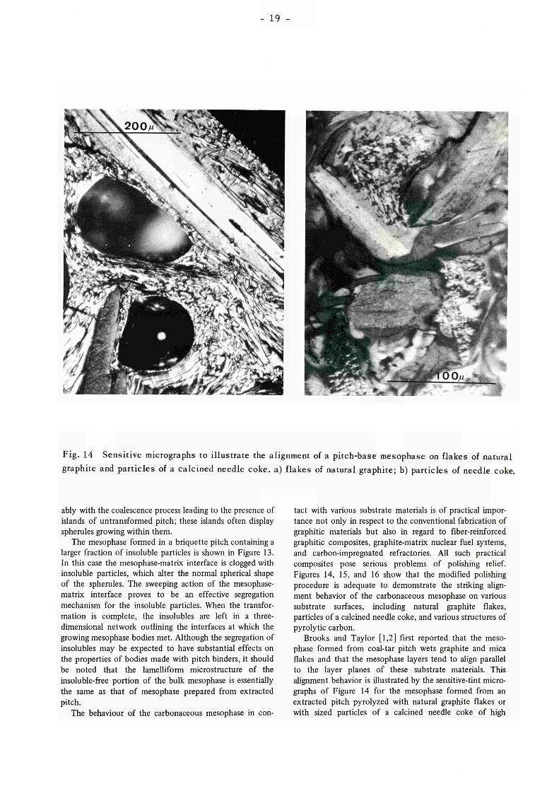
Fig. 14 Sensitive micrographs to illustrate the alignment of a pitch-base mesophase on flakes of natural graphite and particles of a calcined needle coke, a) flakes of natural graphite; b) particles of needle coke.
ably with the coalescence process leading to the presence of islands of untransformed pitch; these islands often display spherules growing within them.
The mesophase formed in a briquette pitch containing a larger fraction of insoluble particles is shown in Figure 13. In this case the mesophase-matrix interface is clogged with insoluble particles, which alter the normal spherical shape of the spherules. The sweeping action of the mesophase-matrix interface proves to be an effective segregation mechanism for the insoluble particles. When the transformation is complete, the insolubles are left in a three-dimensional network outlining the interfaces at which the growing mesophase bodies met. Although the segregation of insolubles may be expected to have substantial effects on the properties of bodies made with pitch binders, it should be noted that the lamelliform microstructure of the insoluble-free portion of the bulk mesophase is essentially the same as that of mesophase prepared from extracted pitch.
The behaviour of the carbonaceous mesophase in con
tact with various substrate materials is of practical importance not only in respect to the conventional fabrication of graphitic materials but also in regard to fiber-reinforced graphitic composites, graphite-matrix nuclear fuel systems, and carbon-impregnated refractories. All such practical composites pose serious problems of polishing relief. Figures 14, 15, and 16 show that the modified polishing procedure is adequate to demonstrate the striking alignment behavior of the carbonaceous mesophase on various substrate surfaces, including natural graphite flakes, particles of a calcined needle coke, and various structures of pyrolytic carbon.
Brooks and Taylor [1,2] first reported that the mesophase formed from coal-tar pitch wets graphite and mica flakes and that the mesophase layers tend to align parallel to the layer planes of these substrate materials. This alignment behavior is illustrated by the sensitive-tint micrographs of Figure 14 for the mesophase formed from an extracted pitch pyrolyzed with natural graphite flakes or with sized particles of a calcined needle coke of high

- 20
graphite naturai flakes
shrinkag cracks
calcined needle coke particles
Fig. 15 The alignment of mesophase layers with graphite substrates. Above: natural graphite flakes in pitch-base mesophase pyrolyzed to 4 3 6 ΐ . Below: calcined needle coke in pitch-base mesophase pyrolyzed to 600°C.

21 -
Fig. l6 The alignment of pitch-base on various structures of pyrolytic carbon coatings prepared in the fluidized bed. Pyrolysis temperature: 555°C. a) 200x, sensitive tint b) 200x, sensitive tint.
preferred orientation. Even after extensive plastic deformation by bubble percolation, the mesophase immediately adjacent to each flake or particle is aligned parallel to the layer planes of the substrate particle. These alignment effects persist through the hardening process. In the case of coke bearing specimens, the alignment effect is sufficiently strong that, after heat-treatment to 1400 °C, polarized-light extinction contours of the coke particle run across the mesophase-coke interface without alteration and it becomes difficult to establish the precise location of the original interface.
The alignment behavior of the carbonaceous mesophase formed by the pyrolysis of an extracted pitch is indicated more explicitly by the structural sketches of Figure 15. There was no evidence for enhanced nucleation of the mesophase on the substrate surfaces. The mesophase appears to nucleate as spherules in the matrix liquid; upon encountering a substrate flake or particle in the bubbling liquid, the mesophase wets the surface and aligns with it.
As shown in Figure 16, the alignment behavior also
occurs with certain pyrolytic carbon structures. Complete wetting occurred with all four structures of the pyrolytic carbon coatings, and alignment is clearly evident with the laminar and columnar structures. Evidence was also obtained of mesophase alignment with the surface of the isotropic structure as well as with the coarser elements of the granular substrate.
CONCLUSION
The problem of understanding the development of the morphology during the pyrolysis of a graphitizable material is unique because the fundamental process of layer alignment involves the formation of a liquid crystal, the carbonaceous mesophase, whose units of structure are large planar aromatic molecules. We 'know little about the structural details of the aromatic platelets or the properties of their assembly as a mesophase, whose existence as a liquid may be only transient before hardening occurs at the

- 22
temperature of the transformation. However the micro-graphic observations permit us to distinguish clearly two regimes of pyrolysis: the liquid range, from the formation of the viscous liquid crystal to its hardening to an effectively solid coke; and the solid range, during which the hard coke gradually softens to a crystalline graphite.
Although the liquid range constitutes, in terms of temperature only a few percent at most of the total range of a graphitizing heat treatment, it is in this short liquid range that the morphological elements of the bulk mesophase are established by three distinctive mechanisms:
1) Nucleation and growth of spherules of liquid mesophase. 2) Coalescence of the spherules and subsequent structural
rearrangement to form bulk mesophase of lamelliform morphology with four types of layer-stacking defects.
3) Deformation of the viscous mesophase by bubble percolation, or other applied stress, leading to intensified folding of the lamellar structure and sharp increases in the density of the layer-stacking defects.
In the practical materials conventionally used in the fabrication of graphitic artifacts, the action of these mechanisms depends on the chemistry of the starting material and is complicated by the interaction of the mesophase with insoluble particles and with substrate materials, such as the filler cokes in a binder-filler artifact.
The focus of attention on the short plastic range of the mesophase introduces difficulties in the preparation of specimens representative of the various stages of micro-structural development which may occur in a temperature range of a few degrees. However the pyrolysis of a series of specimens in a temperature gradient has been found effective, firstly to explore the temperature ranges of interest in a preliminary experiment with a steep gradient, and then to prepare specimens varying as gently as desired in intensity of heat treatment in subsequent experiments with lower but better-placed temperature gradients. The application of this method to simplified specimens, e.g. sized natural graphite flakes in extracted coal-tar pitch, has permitted observations of microstructural characteristics which are difficult to resolve in practical artifacts.
While the mesophase transformation effects the parallel alignment of the pregraphitic aromatic platelets, the starting point for the formation of the characteristic lamelliform morphology of the bulk mesophase is the coalescence process, which appears to proceed by the interleaving of the layers of contiguous mesophase bodies. The degree of refinement of the microstructure depends on the ability of the mesophase to rearrange by flow as ongoing coalescence processes add to the structural complexity by introducing layer-stacking defects. The extent of rearrangement toward a coarse microstructure with relatively few layer-stacking defects is limited by the mesophase viscosity, which increases as pyrolysis continues until the mesophase has hardened.
In this context the work of Ihnatowicz et al. [4] and of Kipling et al. [26] is significant in indicating that the
mesophase viscosity is profoundly affected by the chemical composition and structure of the starting materials as they determine the sequences of pyrolytic reactions producing the mesophase molecules. Despite the complexity of these reactions, the micrographie evidence( e.g., the 'two-phase' structure of Figure 7) indicates that they can be characterized in terms of the microstructures of their coalesced mesophase products. Thus a knowledge of the relationships of the chemical structure of the starting materials to the mesophase microstructures developed on pyrolisis offers a promising approach to the control of morphology in graphitic materials. The openness of this field for further work is demonstrated by the fact that some coke structures of practical significance, e.g., the spherical structures of gilsonite cokes, have yet to be described in terms of their formation by mesophase mechanisms.
The deformation of the plastic mesophase by bubble percolation tends to produce a needle-coke structure in any mesophase which does not harden soon after coalescence. Since the folded and oriented morphology of needle coke is desired for cokes employed in the fabrication of graphite electrodes, it would appear feasible to apply mechanical deformation at a suitable point before hardening to produce cokes of enhanced needle-like character.
After hardening of the mesophase, the principal micro-structural effects of heat-treating through calcination and graphitization temperatures are, in order of occurrence: 1) Shrinkage-cracking opening up lenticular or lamellar
cracks. 2) Fold-sharpening, involving shear displacements to attain
the graphitic interplanar registry. 3) Polygonization, appearing as the formation of mosaic
blocks and kink bands. Shrinkage-cracking, by relaxing the boundary constraints, appears to be an essential precursor to fold-sharpening and polygonization. Important as these latter processes are to the development of graphitic characteristics such as good thermal and electrical conductivity, it should be appreciated that microstructurally these processes comprise only small modifications to the lamelliform morphology established in the liquid range of the mesophase and occur at a scale such that they are best studied by the methods of electron microscopy.
The presence of insoluble particles and substrate grains in the liquid-phase pyrolysis of a graphitizable material has several effects which are relevant to understanding the development of the morphology of commercial binder-filler artifacts. The segregation of insolubles in a coal-tar pitch by the sweeping action of the mesophase transformation boundary leads to a three-dimensional network of insolubles which, in company with their inhibiting action on the coalescence process, would appear detrimental to the mechanical integrity of a fabricated body in which this material served as binder, [12] The difficulty encountered in distinguishing micrographically the three usual components of a commercial graphite, i.e., filler, binder, and imprégnant, is explained by the wetting and aligning

23
characteristics of the carbonaceous mesophase. One can foresee potentional applications of these characteristics in the development of fiber-reinforced carbon composites or in the coating of nuclear fuel particles by liquid-phase pyrolysis.
We believe that the foregoing results indicate that the microstructures of complex graphitic materials can be understood in terms of the behaviour of the carbonaceous mesophase. Accordingly a more complete exploration of the properties of the mesophase formed from the various
starting materials of current or potential interest for graphite fabrication should provide a scientific basis for the control of the morphology. For example, two mechanisms for the manipulation of the morphology are already clear: (1) formation of fine-structured isotropic cokes by adjustment of the chemical composition of the starting material to yield a viscous mesophase with a short liquid range: (2) application of mechanical deformation in the plastic stage of the mesophase to induce a more highly oriented needle-coke structure.
SUMMARY
The microstructures formed during the pyrolysis and heat treatment of graphitizable materials, such as coal-tar pitch and petroleum coke feedstocks, were studied by methods of
polarized-light micrography. The principal features are established in the final stage of liquid-phase pyrolysis after the carbonizing mass has transformed into a liquid crystal, the carbonaceous mesophase, in which the large aromatic layer-molecules are aligned in a lamelliform morphology.
A temperature-gradient heat-treatment technique was found useful to obtain specimens representative of the microstructures which evolve rapidly during the short plastic lifetime of the carbonaceous mesophase. The micro-graphic preparation of the unhardened mesophase was accomplished by modifying established methods for graphitic materials to include a final step of polishing without abrasive. Diamond abrasives were found desirable in the rough and semi-final polishing to counter the relief developed when hard particles are present in unhardened mesophase.
The structural mechanisms operating while the mesophase is plastic are coalescence of the transformed spherules, viscous flow to rearrange the lamelliform defect structure produced by coiaescence, and deformation by the formation and percolation of gas bubbles. The action of the latter mechanism is responsible for the characteristic oriented and folded microstructure of needle cokes, in contrast to the more randomly oriented microstructure of sponge cokes. Insoluble particles present in the pyrolyzing material are segregated by the sweeping action of the transformation boundary. The mesophase wets and aligns its layers parallel to the surface of substrate particles such as flakes of natural graphite or grains of calcined needle coke.
The principal effects of further heat treatment through calcining and graphitizing temperatures are shrinkage-cracking, fold-sharpening, and polygonization. Shrinkage-cracking, appears as an essential precursor to the latter two effects which involve fine-scale bulk displacements to
produce the graphitic interplanar registry. These studies indicate that the microstructure of
graphitic materials is understandable primarily in terms of the behaviour of the carbonaceous mesophase, and further progress toward the control of the morphology of cokes and graphites should result from a more adequate knowledge of the relationships between the chemical composition and structure of the starting material and the behaviour of the mesophase in its short range of plastic existence.
The structural mechanisms operating while the mesophase is plastic are coalescence of the transformed spherules, viscous flow to rearrange the lamelliform defect structure produced by coiaescence, and deformation by the formation and percolation of gas bubbles. The action of the latter mechanism is responsible for the characteristic oriented and folded microstructure of needle cokes, in contrast to the more randomly oriented microstructure of sponge cokes. Insoluble particles present in the pyrolyzing material are segregated by the sweeping action of the transformation boundary. The mesophase wets and aligns its layers paralllel to the surface of substrate particles such as · flakes of natural graphite or grains of calcined needle coke.
The principal effects of further heat treatment through calcining and graphitizing temperatures are shrinkage-cracking, fold-sharpening, and polygonization. Shrinkage-cracking, appears as an essential precursor to the latter two effects which involve fine-scale bulk displacements to produce the graphitic interplanar registry.
These studies indicate that the microstructure of graphitic materials is understandable primarily in terms of the behaviour of the carbonaceous mesophase, and further progress toward the control of the morphology of cokes and graphites should result from a more adequate knowledge oof the relationships between the chemical composition and structure of the starting material and the behaviour of the mesophase in its short range of plastic existence.

ACKNOWLEDGEMENTS
24 -
The authors wish to acknowledge the early and significant contributions of J.M. Pontelandolfo and J.F. Knipping of Gulf General Atomic, San Diego, U.S.A. to solution of the problems of micrographie preparation as well as the assistance of W. Munsonius and B. Nicollin of EURATOM-Petten (Holland) in the development and operation of the temperature-gradient heat-treatment facility. The assistance of C. Souillart in expediting the work and discussing the results is also acknowledged. Special thanks are expressed to Dr. W. Gemmeke of
Verkaufsvereinigung für Teererzeugnisse (Essen, Germany) for the selection and solvent-extraction of representative coal-tar pitches. The petroleum coker feedstocks were kindly supplied by R.W. Van Sant Jr. of Gulf Research Laboratoria (Rotterdam, Holland) and G.B. Engle of Gulf General Atomic. One author, J.L. White, wishes to express his special gratitude to Gulf General Atomic for the opportunity to pursue his work at EURATOM-Petten while on leave of absence and to the European Atomic Energy Community for their generous support of this work.
REFERENCES
1. J.D. Brooks and G.H. Taylor, Carbon, 3 (1965) 185.
2. J.D. Brooks and G.H. Taylor, Chemistry and physics of Carbon, 4 (1968) 243.
3. J.J.Kinpling and P.V. Shooter, Carbon, 4 (1966) 1.
9. L.S. Singer, ibid. 21.
10. H. Marsh and S. Evans, ibid. 42.
11. N. Christou, E. Fitzer, J. Kalka, and W. Schafer, ibid. 50.
12. J.R.Hooker, and R.E. Norman, General Atomic Report GA-4318 (1964).
4. M. Ihnatowicz, P. Chiche, J. Déduit, S. Pregermain, and R. Tournant, Carbon, 4 (1966) 41, available in English translation as General Atomic Report GA-tr-7382 (January, 1967).
5. J.L. White, G.L. Guthrie and J.O. Gardner, Carbon, 5 (1967)517.
13. R.L. Hales and E.M. Woodruff, Proc. Fifth Conf. on Carbon, 1 (1962)456.
14. M. Letort, J.Chim.Phys., special number (April, 1969) 9.
15. P. Chiche, J. Déduit, and F. Fischer, ibid., 28.
6. J.L. White, J. Dubois and C. Souillart, J. Chim. Phys., special volume (April 1969) 33; available in English translation as EURATOM report 4094e (1969)
7. H. Honda, H. Kimura, Y. Sanada, S. Sugawara, and T. Furuta, Carbon, to be published.
16. CF . Stout, M. Janes, and J.A. Biehl, USAF Systems Command, WADD Tech. Report 61-72, Vol. XXXVI (1964); available from Office of Technical Services, U.S. Dept. of commerce, Washington, D.C.
17. C.B. Scott, Chemistry and Industry, 1967, 1124.
8. H.E. Blayden, J. Chim. Phys., special volume (April, 1969)15.
18. I. Pincus and N.J. Gendron, Proc. Fourth Conf. on Carbon (1960) 687.

25 -
19. T.J. Clark, USAEC Report HW-68182, Part 1 (1961).
20. J.T. McCartney and S. Ergun, Proc. Third Conf. on
Carbon (1959) 223·
21 . J. Déduit, in Les Carbones, edited by A. Pacault ,
Masson, Paris , 1965, p. 19.
22. R.J. Gray and J. V. Cathcart, J. Nuclear Materials,
1 9 ( 1 9 6 6 ) 8 1 .
23. M.C. Smith, Bull. Am. Ceram, S o c , 48 (1969) 890.
24. J.C. Bokros, G.L. Guthrie, R.W. Dunlap, and A.S.
Schwartz, J. Nucí. Materials, 31 (1969) 25.
25. A.L. Pitner, Ninth Biennial Conf. on Carbon, Summary of Papers, (1969) ; s e e a l so Batterle Northwest Laboratory Report BNWL-SA-WRYI (1969).
26. J.J. Kipling, P.V. Shooter, and R.N. Young,Carbon,
4 (1966) 333.
27. W.E. Smith and W.L. Harper, Ninth Biennial Conf.
on Carbon, Summary of Papers, (1969) 27.
28. W. 0. Ruland, Ninth Biennial Conf. on Carbon, to
be published.
29. W.O. Ruland, Chemistry and Phys ics of Carbon, 4,
(1968) 53-
30. E. M. Woodruff, J. Chim. Phys . , spec ia l volume (A-
pril, 1969) 96; for detailed accounts s e e Batel le
Northwest Laboratory Reports BNWL-SA-1903 (1968)
and BNWL-SA-2605 (1969).


27
Fig. 10
K / mm
^Α
^^t/ .:■■■'· ■ ' ■ ■ ■ ■
m^M ■&.
Λ^β ■
lå
Vf Fig. 11a Fig. 11b

28
Fig. 14a Fig. 14b
Fig. 16a Fig. 16b

aç$tp 11?
'üRüÜRi '■"HgRft
U t * * «
SläNilill^l^l' l ap
Äa «
f ι l rtdBi'iM
w
fi«
l ' I l i
'Γ.
Wßmt
;;:;;;:;;:: l ü \:. To disseminate knowledge is to disseminate prosperity — I mean
; general prosperity and not individual riches — and with prosperity
Jill!!!: M- :U vrtti t , \ w
H! ï · I' disappears the greater part of the evil which is our heritage from :::::::::::::::::
WSSVt' ' Ì l i Ι!!!!::::
Illiå I darker times.
Alfred Nobel kfcttift T'IiiSnlîtliîjllÎ! aï», π
% 'J
m

SI EM
SALES OFFICES
Ail repor t s published by the Commiss ion of the European Communi t ies are on sale at the offices listed below, at the prices given on the back of the front cover. When order ing, specify clearly the EUR n u m b e r and the title of the repor t which are shown on the front cover.
OFFICE FOR OFFICIAL PUBLICATIONS OF T H E EUROPEAN COMMUNITIES P.O. Box 1003 - Luxembourg/station 37, rue Glesener, Luxembourg (Compte chèque postal N° 191-90)
B E L G I Q U E — BELGIË M O N I T E U R B E L G E Rue de Louvain, 40-42 - B-1000 Bruxelles BELGISCH STAATSBLAD Leuvense weg 40-42 - B-1000 Brussel
D E U T S C H L A N D VERLAG B U N D E S A N Z E I G E R Postfach 108 006 - D-5 Köln 1
F R A N C E SERVICE D E V E N T E EN FRANCE DES PUBLICATIONS DES COMMUNAUTÉS E U R O P É E N N E S rue Desaix, 26 - F-75 Paris 15«
ITALIA L I B R E R I A D E L L O STATO Piazza G. Verdi, 10 - 1-00198 Roma
L U X E M B O U R G OFFICE D E S PUBLICATIONS O F F I C I E L L E S DES COMMUNAUTÉS E U R O P É E N N E S Case Postale 1003 - Luxembourg/gare 37, rue Glesener - Luxembourg
N E D E R L A N D S T A A T S D R U K K E R I J en U I T G E V E R S B E D R I J F Christoffel Plant i jnstraat - Den Haag
spi U N I T E D K I N G D O M
H. M. STATIONERY OFFICE P.O. Box 569 - London S.E.I
loi
»Jl >i'li-1tlii--!,J'4iif
itlilr-fuiPW Commiss ion of the European Communi t ies D.G. XIII - C.I.D. 29, rue Aldringer L u x e m b o u r g
: fS i* j * ' .!ft!'J4|!
CDNA04627ENC
H9RHB«