Embed Size (px)
Citation preview
150
Original Article
International Clinical Neuroscience Journal • Vol 3, No 3, Summer 2016
The Nucleus Pulpous of Intervertebral Disc Effect on Finite Element Modeling of SpineMidiya Khademi1, Yousef Mohammadi2, Seifollah Gholampour3, Nasser Fatouraee4
1 M.Sc. Department of Biomedical Engineering, Tehran North Branch, Islamic Azad University, Tehran, Iran2 Ph.D. Student of Biomechanical Engineering, Biomechanics Department, Biomedical Engineering Faculty, Amirkabir University of Technology, Tehran, Iran3 Ph.D. Assistant Professor of Biomechanical Engineering, Department of Biomedical Engineering, North Tehran Branch, Islamic Azad University, Tehran, Iran4 Ph.D. Associate Professor of Biomechanical Engineering, Biological Fluid Mechanics Research Laboratory, Biomechanics Department, Biomedical Engineering Faculty, Amirkabir University of Technology
ABSTRACT
Background: Spine of an adult is made up of five areas that include 7 cervical vertebrae, 12 thoracic vertebrae, 5 lumbar vertebrae, sacrum and finally coccyx. Selecting appropriate assumptions for modeling and biological analysis of the spine components has a significant impact on the accuracy of results in biomechanical simulation for different modes.Methods: In the present study, biomechanical analysis has been done on the spine by using finite element simulation. Dimensional characteristics of an individual’s spine components are obtained, then the spine model as one-piece and intervertebral discs as two modes of one-piece and two-piece (Annulus and Nucleus section) in the form of two separate models is modeled. Gravity caused by the weight of spine (gravity intensity of 9800 Newton per square millimeters) was applied to the model and output of stress, displacement and changing the angle between the vertebrae of the spine has been obtained.Results: The maximum displacement, stress and change of angle between the vertebrae in spine model with one-piece disc was 0.254 and 0.197 and -0.083 respectively, and for the model with two-piece disc is 0.399 and 0.205 and 0.021 respectively.Conclusion: According to the results for examining the stress, there was no significant difference in choosing the assumption of two-piece or one-piece of the intervertebral disc, but results of the model analysis with assuming two pieces of the intervertebral disc is more appropriate in examining displacement and changing the angle between the vertebrae.Keywords: Spinal Alignment; Range of Motion; Vertebrae Spine; Annulus, Nucleus
INTRODUCTIONSpine has a complex structure which is presented under
title of a body column and limbs and trunks are connected on the area. This column is the mechanical axis of the human body that is responsible for the stability, mobility of trunk and extremities and also the protection of spinal cord. This column is axis of the skeleton in the upper torso
and begins from skull base and extends through all neck and trunk. Recognition and explanation of the operation of spine to check the abnormalities is important 1. Spine in children consists of 33 vertebrae, but their number in adult decreases to 23 due to fusion of ending vertebrae and creating the vertebrae of sacrum and coccyx. Since the load and torque applied to the lower spine is bigger,
ICNSJ 2016; 3 (3) :150-157 www.journals.sbmu.ac.ir/neuroscience
Correspondence to: Nasser Fatouraee Ph.D. Biological Fluid Mechanics Research Laboratory, Biomechanics Department, Biomedical Engineering Faculty, Amirkabir University of Technology, Tehran, Iran; Telefax: +98-21 64542368; E-mail: [email protected]: September 12, 2016 Accepted: August 18, 2016
Nucleus Pulpous in Finite Element Modeling of Spine—Khademi et al
151International Clinical Neuroscience Journal • Vol 3, No 3, Summer 2016
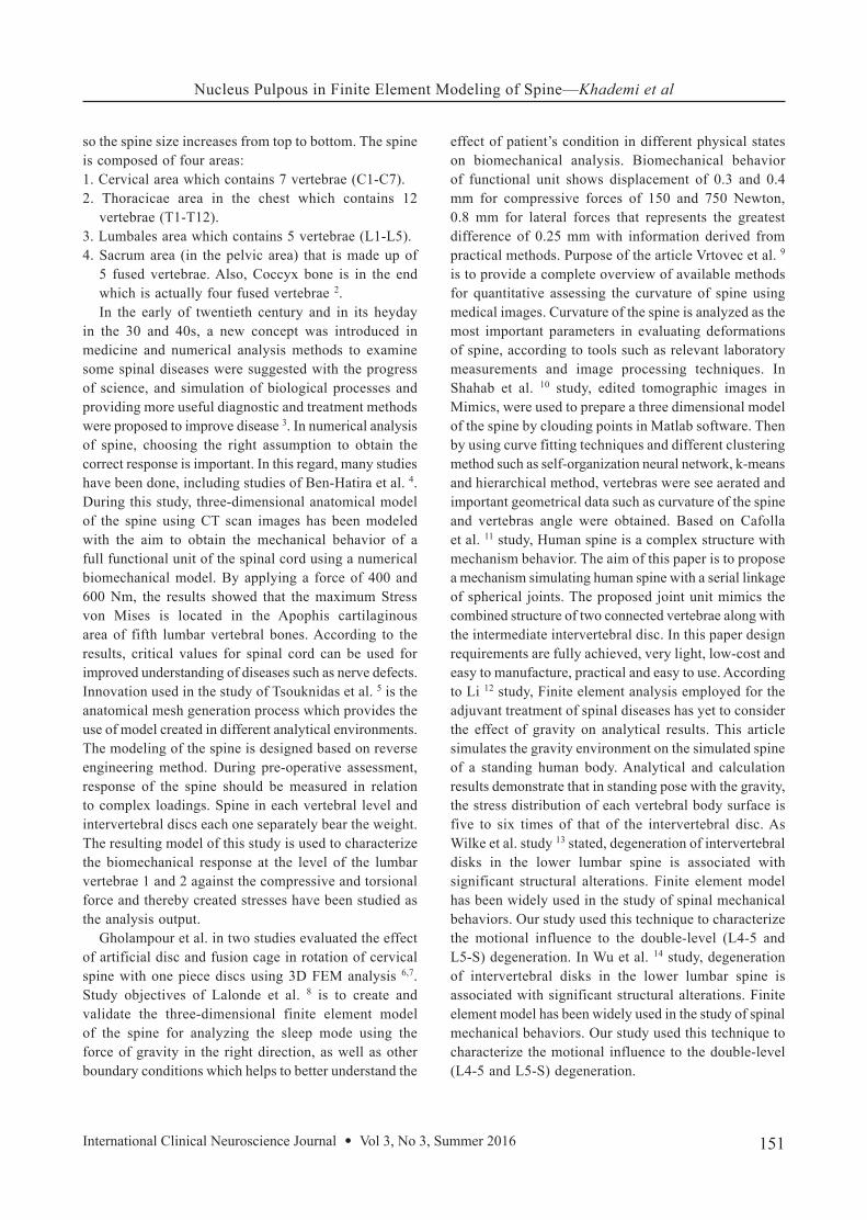
so the spine size increases from top to bottom. The spine is composed of four areas:1. Cervical area which contains 7 vertebrae (C1-C7).2. Thoracicae area in the chest which contains 12
vertebrae (T1-T12).3. Lumbales area which contains 5 vertebrae (L1-L5).4. Sacrum area (in the pelvic area) that is made up of
5 fused vertebrae. Also, Coccyx bone is in the end which is actually four fused vertebrae 2.In the early of twentieth century and in its heyday
in the 30 and 40s, a new concept was introduced in medicine and numerical analysis methods to examine some spinal diseases were suggested with the progress of science, and simulation of biological processes and providing more useful diagnostic and treatment methods were proposed to improve disease 3. In numerical analysis of spine, choosing the right assumption to obtain the correct response is important. In this regard, many studies have been done, including studies of Ben-Hatira et al. 4. During this study, three-dimensional anatomical model of the spine using CT scan images has been modeled with the aim to obtain the mechanical behavior of a full functional unit of the spinal cord using a numerical biomechanical model. By applying a force of 400 and 600 Nm, the results showed that the maximum Stress von Mises is located in the Apophis cartilaginous area of fifth lumbar vertebral bones. According to the results, critical values for spinal cord can be used for improved understanding of diseases such as nerve defects. Innovation used in the study of Tsouknidas et al. 5 is the anatomical mesh generation process which provides the use of model created in different analytical environments. The modeling of the spine is designed based on reverse engineering method. During pre-operative assessment, response of the spine should be measured in relation to complex loadings. Spine in each vertebral level and intervertebral discs each one separately bear the weight. The resulting model of this study is used to characterize the biomechanical response at the level of the lumbar vertebrae 1 and 2 against the compressive and torsional force and thereby created stresses have been studied as the analysis output.
Gholampour et al. in two studies evaluated the effect of artificial disc and fusion cage in rotation of cervical spine with one piece discs using 3D FEM analysis 6,7. Study objectives of Lalonde et al. 8 is to create and validate the three-dimensional finite element model of the spine for analyzing the sleep mode using the force of gravity in the right direction, as well as other boundary conditions which helps to better understand the
effect of patient’s condition in different physical states on biomechanical analysis. Biomechanical behavior of functional unit shows displacement of 0.3 and 0.4 mm for compressive forces of 150 and 750 Newton, 0.8 mm for lateral forces that represents the greatest difference of 0.25 mm with information derived from practical methods. Purpose of the article Vrtovec et al. 9 is to provide a complete overview of available methods for quantitative assessing the curvature of spine using medical images. Curvature of the spine is analyzed as the most important parameters in evaluating deformations of spine, according to tools such as relevant laboratory measurements and image processing techniques. In Shahab et al. 10 study, edited tomographic images in Mimics, were used to prepare a three dimensional model of the spine by clouding points in Matlab software. Then by using curve fitting techniques and different clustering method such as self-organization neural network, k-means and hierarchical method, vertebras were see aerated and important geometrical data such as curvature of the spine and vertebras angle were obtained. Based on Cafolla et al. 11 study, Human spine is a complex structure with mechanism behavior. The aim of this paper is to propose a mechanism simulating human spine with a serial linkage of spherical joints. The proposed joint unit mimics the combined structure of two connected vertebrae along with the intermediate intervertebral disc. In this paper design requirements are fully achieved, very light, low-cost and easy to manufacture, practical and easy to use. According to Li 12 study, Finite element analysis employed for the adjuvant treatment of spinal diseases has yet to consider the effect of gravity on analytical results. This article simulates the gravity environment on the simulated spine of a standing human body. Analytical and calculation results demonstrate that in standing pose with the gravity, the stress distribution of each vertebral body surface is five to six times of that of the intervertebral disc. As Wilke et al. study 13 stated, degeneration of intervertebral disks in the lower lumbar spine is associated with significant structural alterations. Finite element model has been widely used in the study of spinal mechanical behaviors. Our study used this technique to characterize the motional influence to the double-level (L4-5 and L5-S) degeneration. In Wu et al. 14 study, degeneration of intervertebral disks in the lower lumbar spine is associated with significant structural alterations. Finite element model has been widely used in the study of spinal mechanical behaviors. Our study used this technique to characterize the motional influence to the double-level (L4-5 and L5-S) degeneration.
Nucleus Pulpous in Finite Element Modeling of Spine—Khademi et al
152 International Clinical Neuroscience Journal • Vol 3, No 3, Summer 2016
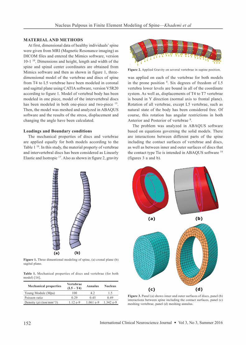
MATERIAL AND METHODS At first, dimensional data of healthy individuals’ spine
were given from MRI (Magnetic Resonance imaging) as DICOM files and entered the Mimics software, version 10-1 10. Dimensions and height, length and width of the spine and spinal center coordinates are obtained from Mimics software and then as shown in figure 1, three-dimensional model of the vertebrae and discs of spine from T4 to L5 vertebrae have been modeled in coronal and sagittal plane using CATIA software, version V5R20 according to figure 1. Model of vertebral body has been modeled in one piece, model of the intervertebral discs has been modeled in both one-piece and two-piece 15. Then, the model was meshed and analyzed in ABAQUS software and the results of the stress, displacement and changing the angle have been calculated.
Loadings and Boundary conditionsThe mechanical properties of discs and vertebrae
are applied equally for both models according to the Table 1 16. In this study, the material property of vertebrae and intervertebral discs has been considered as Linearly Elastic and Isotropic 17. Also as shown in figure 2, gravity
was applied on each of the vertebrae for both models in the prone position 8. Six degrees of freedom of L5 vertebra lower levels are bound in all of the coordinate system. As well as, displacements of T4 to T7 vertebrae is bound in Y direction (normal axis to frontal plane). Rotation of all vertebrae, except L5 vertebrae, such as natural state of the body has been considered free. Of course, this rotation has angular restrictions in both Anterior and Posterior of vertebrae 8.
The problem was analyzed in ABAQUS software based on equations governing the solid models. There are interactions between different parts of the spine including the contact surfaces of vertebrae and discs, as well as between inner and outer surfaces of discs that the contact type Tie is intended in ABAQUS software 18 (figures 3 a and b).
NucleusAnnalusVertebrae(L5 – T4) Mechanical properties
1.54.2100Young Module (Mpa)0.490.450.29Poisson ratio
1.342 e-91.061 e-91.12 e-9Density (ρ) (ton/mm^3)
Table 1. Mechanical properties of discs and vertebrae (for both model) [16].
Figure 1. Three dimentional modeling of spine, (a) cronal plane (b) sagital plane.
Figure 2. Applied Gravity on several vertebrae in supine position.
Figure 3. Panel (a) shows inner and outer surfaces of discs, panel (b) interactions between spine including the contact surfaces, panel (c) meshing vertebrae, panel (d) meshing annulus.
Nucleus Pulpous in Finite Element Modeling of Spine—Khademi et al
153International Clinical Neuroscience Journal • Vol 3, No 3, Summer 2016
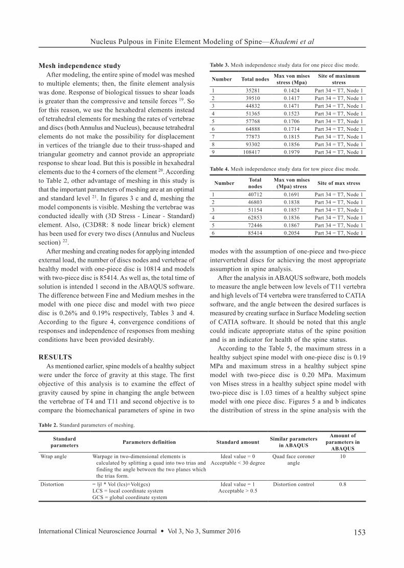
Mesh independence studyAfter modeling, the entire spine of model was meshed
to multiple elements; then, the finite element analysis was done. Response of biological tissues to shear loads is greater than the compressive and tensile forces 19. So for this reason, we use the hexahedral elements instead of tetrahedral elements for meshing the rates of vertebrae and discs (both Annulus and Nucleus), because tetrahedral elements do not make the possibility for displacement in vertices of the triangle due to their truss-shaped and triangular geometry and cannot provide an appropriate response to shear load. But this is possible in hexahedral elements due to the 4 corners of the element 20. According to Table 2, other advantage of meshing in this study is that the important parameters of meshing are at an optimal and standard level 21. In figures 3 c and d, meshing the model components is visible. Meshing the vertebrae was conducted ideally with (3D Stress - Linear - Standard) element. Also, (C3D8R: 8 node linear brick) element has been used for every two discs (Annulus and Nucleus section) 22.
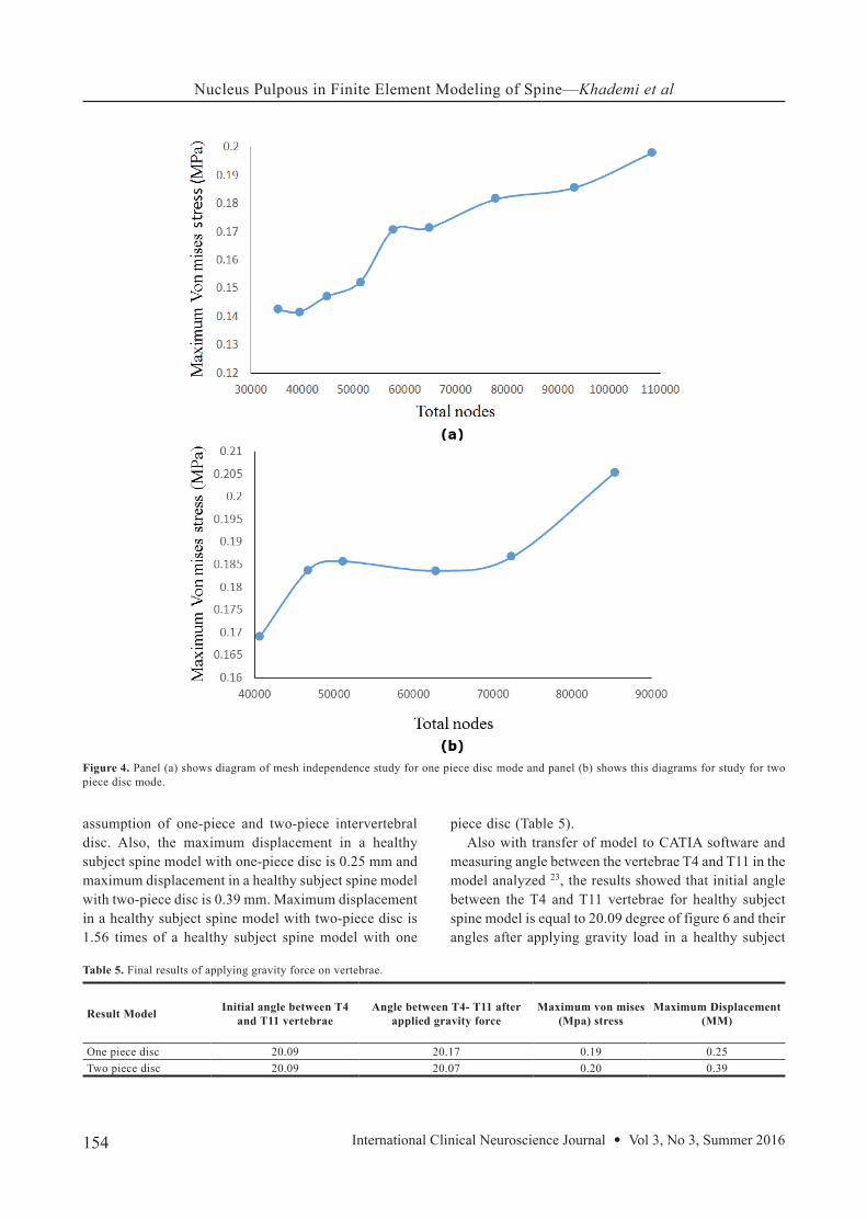
After meshing and creating nodes for applying intended external load, the number of discs nodes and vertebrae of healthy model with one-piece disc is 10814 and models with two-piece disc is 85414. As well as, the total time of solution is intended 1 second in the ABAQUS software. The difference between Fine and Medium meshes in the model with one piece disc and model with two piece disc is 0.26% and 0.19% respectively, Tables 3 and 4. According to the figure 4, convergence conditions of responses and independence of responses from meshing conditions have been provided desirably.
RESULTS As mentioned earlier, spine models of a healthy subject
were under the force of gravity at this stage. The first objective of this analysis is to examine the effect of gravity caused by spine in changing the angle between the vertebrae of T4 and T11 and second objective is to compare the biomechanical parameters of spine in two
modes with the assumption of one-piece and two-piece intervertebral discs for achieving the most appropriate assumption in spine analysis.
After the analysis in ABAQUS software, both models to measure the angle between low levels of T11 vertebra and high levels of T4 vertebra were transferred to CATIA software, and the angle between the desired surfaces is measured by creating surface in Surface Modeling section of CATIA software. It should be noted that this angle could indicate appropriate status of the spine position and is an indicator for health of the spine status.
According to the Table 5, the maximum stress in a healthy subject spine model with one-piece disc is 0.19 MPa and maximum stress in a healthy subject spine model with two-piece disc is 0.20 MPa. Maximum von Mises stress in a healthy subject spine model with two-piece disc is 1.03 times of a healthy subject spine model with one piece disc. Figures 5 a and b indicates the distribution of stress in the spine analysis with the
Amount of parameters in
ABAQUS
Similar parameters in ABAQUSStandard amountParameters definitionStandard
parameters
10Quad face coroner angle
Ideal value = 0Acceptable < 30 degree
Warpage in two-dimensional elements is calculated by splitting a quad into two trias and finding the angle between the two planes which the trias form.
Wrap angle
0.8Distortion controlIdeal value = 1Acceptable > 0.5
= ‖j‖ * Vol (lcs)+Vol(gcs)LCS = local coordinate systemGCS = global coordinate system
Distortion
Table 2. Standard parameters of meshing.
Site of maximum stress
Max von mises stress (Mpa)Total nodesNumber
Part 34 = T7, Node 10.1424352811Part 34 = T7, Node 10.1417395102Part 34 = T7, Node 10.1471448323Part 34 = T7, Node 10.1523513654Part 34 = T7, Node 10.1706577685Part 34 = T7, Node 10.1714648886Part 34 = T7, Node 10.1815778737Part 34 = T7, Node 10.1856933028Part 34 = T7, Node 10.19791084179
Table 3. Mesh independence study data for one piece disc mode.
Site of max stressMax von mises (Mpa) stress
Total nodesNumber
Part 34 = T7, Node 10.1691407121Part 34 = T7, Node 10.1838468032Part 34 = T7, Node 10.1857511543Part 34 = T7, Node 10.1836628534Part 34 = T7, Node 10.1867724465Part 34 = T7, Node 10.2054854146
Table 4. Mesh independence study data for tow piece disc mode.
Nucleus Pulpous in Finite Element Modeling of Spine—Khademi et al
154 International Clinical Neuroscience Journal • Vol 3, No 3, Summer 2016
assumption of one-piece and two-piece intervertebral disc. Also, the maximum displacement in a healthy subject spine model with one-piece disc is 0.25 mm and maximum displacement in a healthy subject spine model with two-piece disc is 0.39 mm. Maximum displacement in a healthy subject spine model with two-piece disc is 1.56 times of a healthy subject spine model with one
piece disc (Table 5).Also with transfer of model to CATIA software and
measuring angle between the vertebrae T4 and T11 in the model analyzed 23, the results showed that initial angle between the T4 and T11 vertebrae for healthy subject spine model is equal to 20.09 degree of figure 6 and their angles after applying gravity load in a healthy subject
Figure 4. Panel (a) shows diagram of mesh independence study for one piece disc mode and panel (b) shows this diagrams for study for two piece disc mode.
Maximum Displacement(MM)
Maximum von mises(Mpa) stress
Angle between T4- T11 after applied gravity force
Initial angle between T4 and T11 vertebraeResult Model
0.250.1920.1720.09One piece disc0.390.2020.0720.09Two piece disc
Table 5. Final results of applying gravity force on vertebrae.
Nucleus Pulpous in Finite Element Modeling of Spine—Khademi et al
155International Clinical Neuroscience Journal • Vol 3, No 3, Summer 2016
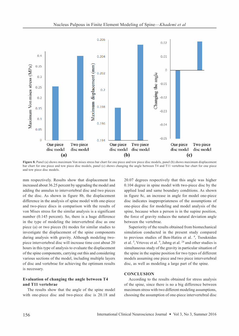
spine model with one-piece is equal to 20.18 degree figure 7a for a healthy subject spine model with two-piece disc is equal to 20.07 degree figure 7b. Changing the angle between the T4 and T11 vertebrae for a healthy subject spine model with two-piece disc is 0.104 degree higher than the healthy subject spine model with one-piece.
DISCUSSIONEvaluation of von Mises stress
It should be noted because the facet joints and the transverse processes of the vertebrae do not have a great impact on changing the considered angle and displacement of the vertebrae, modeling of these areas has been neglected in this study. The logic has been used in recent studies for different biological analysis of spine as well 8.
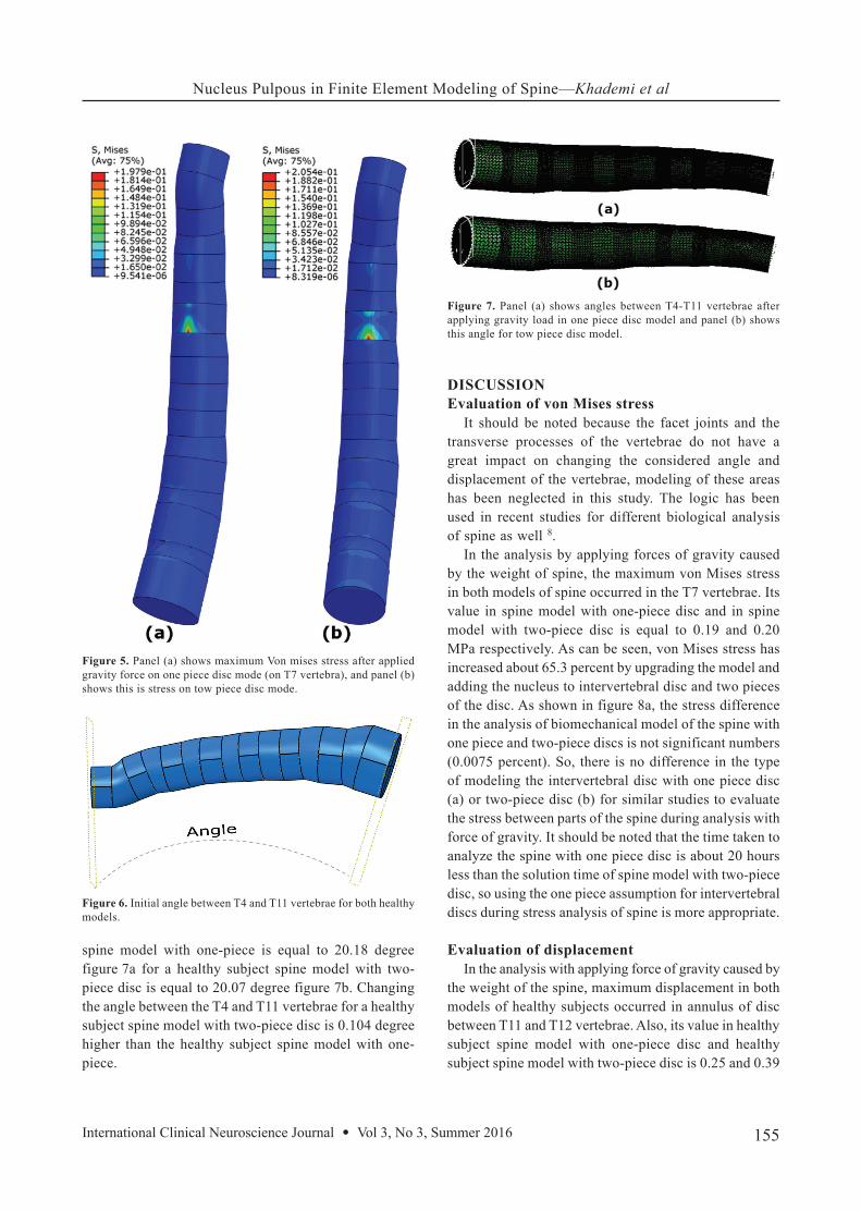
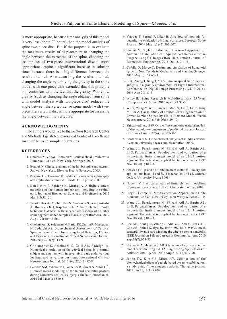
In the analysis by applying forces of gravity caused by the weight of spine, the maximum von Mises stress in both models of spine occurred in the T7 vertebrae. Its value in spine model with one-piece disc and in spine model with two-piece disc is equal to 0.19 and 0.20 MPa respectively. As can be seen, von Mises stress has increased about 65.3 percent by upgrading the model and adding the nucleus to intervertebral disc and two pieces of the disc. As shown in figure 8a, the stress difference in the analysis of biomechanical model of the spine with one piece and two-piece discs is not significant numbers (0.0075 percent). So, there is no difference in the type of modeling the intervertebral disc with one piece disc (a) or two-piece disc (b) for similar studies to evaluate the stress between parts of the spine during analysis with force of gravity. It should be noted that the time taken to analyze the spine with one piece disc is about 20 hours less than the solution time of spine model with two-piece disc, so using the one piece assumption for intervertebral discs during stress analysis of spine is more appropriate.
Evaluation of displacementIn the analysis with applying force of gravity caused by
the weight of the spine, maximum displacement in both models of healthy subjects occurred in annulus of disc between T11 and T12 vertebrae. Also, its value in healthy subject spine model with one-piece disc and healthy subject spine model with two-piece disc is 0.25 and 0.39
Figure 6. Initial angle between T4 and T11 vertebrae for both healthy models.
Figure 5. Panel (a) shows maximum Von mises stress after applied gravity force on one piece disc mode (on T7 vertebra), and panel (b) shows this is stress on tow piece disc mode.
Figure 7. Panel (a) shows angles between T4-T11 vertebrae after applying gravity load in one piece disc model and panel (b) shows this angle for tow piece disc model.
Nucleus Pulpous in Finite Element Modeling of Spine—Khademi et al
156 International Clinical Neuroscience Journal • Vol 3, No 3, Summer 2016
mm respectively. Results show that displacement has increased about 36.25 percent by upgrading the model and adding the annulus to intervertebral disc and two pieces of the disc. As shown in figure 8b, the displacement difference in the analysis of spine model with one-piece and two-piece discs in comparison with the results of von Mises stress for the similar analysis is a significant number (0.145 percent). So, there is a huge difference in the type of modeling the intervertebral disc as one piece (a) or two pieces (b) modes for similar studies to investigate the displacement of the spine components during analysis with gravity. Although modeling two-piece intervertebral disc will increase time cost about 20 hours in this type of analysis to evaluate the displacement of the spine components, carrying out this and considering various sections of the model, including multiple layers of disc and vertebrae for achieving the optimum results is necessary.
Evaluation of changing the angle between T4 and T11 vertebrae
The results show that the angle of the spine model with one-piece disc and two-piece disc is 20.18 and
20.07 degrees respectively that this angle was higher 0.104 degree in spine model with two-piece disc by the applied load and same boundary conditions. As shown in figure 8c, an increase in angle for model one-piece disc indicates inappropriateness of the assumptions of one-piece disc for modeling and model analysis of the spine, because when a person is in the supine position, the force of gravity reduces the natural deviation angle between the vertebrae.
Superiority of the results obtained from biomechanical simulation conducted in the present study compared to previous studies of Ben-Hatira et al. 4, Tsouknidas et al. 5, Vrtovec et al. 9, Jahng et al. 24 and other studies is simultaneous study of the gravity in particular situation of the spine in the supine position for two types of different models assuming one piece and two piece intervertebral disc, as well as modeling a large part of the spine.
CONCLUSION According to the results obtained for stress analysis
of the spine, since there is no a big difference between maximum stress with two different modeling assumptions, choosing the assumption of one-piece intervertebral disc
Figure 8. Panel (a) shows maximum Von mises stress bar chart for one piece and tow piece disc models, panel (b) shows maximum displacement bar chart for one piece and tow piece disc models, panel (c) shows changing the angle between T4 and T11 vertebrae bar chart for one piece and tow piece disc models.
Nucleus Pulpous in Finite Element Modeling of Spine—Khademi et al
157International Clinical Neuroscience Journal • Vol 3, No 3, Summer 2016
is more appropriate, because time analysis of this model is very less (about 20 hours) than the model analysis of spine two-piece disc. But if the purpose is to evaluate the maximum results of displacement or changing the angle between the vertebrae of the spine, choosing the assumption of two-piece intervertebral disc is more appropriate despite a significant increase in solution time, because there is a big difference between the results obtained. Also according the results obtained, changing the angle by applying the gravity in the spine model with one-piece disc extended that this principle is inconsistent with the fact that the gravity. While low gravity (such as changing the angle obtained from spine with model analysis with two-piece disc) reduces the angle between the vertebrae, so spine model with two-piece intervertebral disc is more appropriate for assessing the angle between the vertebrae.
ACKNOWLEDGMENTS The authors would like to thank Noor Research Center
and Shohada Tajrish Neurosurgical Centre of Excellence for their helps in sample collections.
REFERENCES 1. Daniels JM, editor. Common Musculoskeletal Problems: A
Handbook. 3nd ed. New York. Springer; 2015.
2. Bogduk N. Clinical anatomy of the lumbar spine and sacrum. 3nd ed. New York. Elsevier Health Sciences; 2005.
3. Peterson DR, Bronzino JD, editors. Biomechanics: principles and applications. 2nd ed. Florida. CRC press; 2007.
4. Ben-Hatira F, Saidane K, Mrabet A. A finite element modeling of the human lumbar unit including the spinal cord. Journal of Biomedical Science and Engineering. 2012 Mar 1;5(3):150.
5. Tsouknidas A, Michailidis N, Savvakis S, Anagnostidis K, Bouzakis KD, Kapetanos G. A finite element model technique to determine the mechanical response of a lumbar spine segment under complex loads. J Appl Biomech. 2012 Aug 1;28(4):448-56.
6. Gholampour S, Soleimani N, Karizi FZ, Zalii AR, Masoudian N, Seddighi AS. Biomechanical Assessment of Cervical Spine with Artificial Disc during Axial Rotation, Flexion and Extension. International Clinical Neuroscience Journal. 2016 Sep 22;3(2):113-9.
7. Gholampour S, Soleimani N, Zalii AR, Seddighi A. Numerical simulation of the cervical spine in a normal subject and a patient with intervertebral cage under various loadings and in various positions. International Clinical Neuroscience Journal. 2016 Sep 22;3(2):92-8.
8. Lalonde NM, Villemure I, Pannetier R, Parent S, Aubin CÉ. Biomechanical modeling of the lateral decubitus posture during corrective scoliosis surgery. Clinical Biomechanics. 2010 Jul 31;25(6):510-6.
9. Vrtovec T, Pernuš F, Likar B. A review of methods for quantitative evaluation of spinal curvature. European Spine Journal. 2009 May 1;18(5):593-607.
10. Shahab M, Seyfi B, Fatouraee N. A novel Approach for Automatic Calculation of Required Parameters in Spine Surgery using CT Images Row Data. Iranian Journal of Biomedical Engineering. 2015 Oct 18;9:1-15.
11. Cafolla D, Marco C. Design and simulation of humanoid spine. In New Trends in Mechanism and Machine Science. 2015 May 1;1:585-593.
12. Li K, Zhang J, Jiang J, Ma S. Lumbar spinal finite element analysis in a gravity environment. In Eighth International Conference on Digital Image Processing (ICDIP 2016). 2016 Aug 29;1:1-5.
13. Wilke HJ. Spine Research Is Multidisciplinary: 25 Years of Experiences. Spine. 2016 Apr 1;41:S1-3.
14. Wu Y, Wang Y, Wu J, Guan J, Mao N, Lu C, Lv R, Ding M, Shi Z, Cai B. Study of Double-level Degeneration of Lower Lumbar Spines by Finite Element Model. World Neurosurgery. 2016 Feb 29;86:294-9.
15. Shirazi-Adl, A., 1989. On the fibre composite material models of disc annulus—comparison of predicted stresses. Journal of Biomechanics, 22(4), pp.357-365.
16. Bahramshahi N. Finite element analysis of middle cervical. Ryerson university theses and dissertation; 2009.
17. Wang JL, Parnianpour M, Shirazi-Adl A, Engin AE, Li S, Patwardhan A. Development and validation of a viscoelastic finite element model of an L2/L3 motion segment. Theoretical and applied fracture mechanics. 1997 Nov 30;28(1):81-93.
18. Schwab CH. p-and hp-finite element methods: Theory and applications in solid and fluid mechanics. 1nd ed. Oxford: Oxford University Press; 1998.
19. Nassehi V. Practical aspects of finite element modelling of polymer processing. 1nd ed. Chichester: Wiley; 2002.
20. Frey PJ, George PL. Mesh Generation: Application to Finite Elements. 2nd ed. New Jersey. John Wiley & Sons; 2010.
21. Wang JL, Parnianpour M, Shirazi-Adl A, Engin AE, Li S, Patwardhan A. Development and validation of a viscoelastic finite element model of an L2/L3 motion segment. Theoretical and applied fracture mechanics. 1997 Nov 30;28(1):81-93.
22. Lee MJ, Zhang R, Zheng J, Ahn GS, Zhu C, Park TR, Cho SR, Shin CS, Ryu JS. IEEE 802.15. 5 WPAN mesh standard-low rate part: Meshing the wireless sensor networks. IEEE Journal on Selected Areas in Communications. 2010 Sep;28(7):973-83.
23. Skarka W. Application of MOKA methodology in generative model creation using CATIA. Engineering Applications of Artificial Intelligence. 2007 Aug 31;20(5):677-90.
24. Jahng TA, Kim YE, Moon KY. Comparison of the biomechanical effect of pedicle-based dynamic stabilization: a study using finite element analysis. The spine journal. 2013 Jan 31;13(1):85-94.