Embed Size (px)
Citation preview
GUIDE
200.V
2
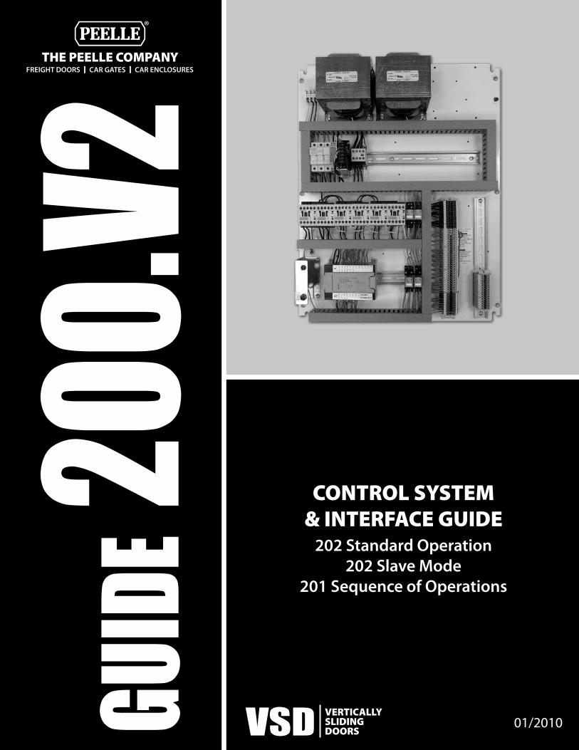
CONTROL SYSTEM& INTERFACE GUIDE
202 Standard Operation202 Slave Mode
201 Sequence of Operations
VSD VERTICALLY SLIDINGDOORS
01/2010
FREIGHT DOORS I CAR GATES I CAR ENCLOSURESTHE PEELLE COMPANY
®

MANUAL 202-STANDARD - SERIES 2742-PLC_2010_sV6.3 Standard Operation - Freight Door Control Interface and Initiating Contacts
1
www.peelledoor.com
FREIGHT ELEVATOR POWER DOOR INTERFACE AND INITIATING CONTACT REQUIREMENTS
FOR CONTROLLER SERIES #2742-PLC
STANDARD OPERATION (FOR SLAVE TYPE CONTROL SEE MANUAL 202-SLAVE)
TABLE OF CONTENTS 1. CONTROL SETTING INPUTS
1.1 POWER SWITCH 1.2 STANDARD AND SLAVE OPERATION 1.3 AUTOMATIC TIME CLOSING OPERATION SETUP 1.4 OPEN AND CLOSE DIRECTION TIMERS
2. ELEVATOR CONTROL INITIATIONS: CONTACTS REQUIRED BY THE ELEVATOR CONTROLLER 2.1 BASIC INITIATIONS:
2.1.1 RETIRING CAM 2.1.2 AUTOMATIC OPEN 2.1.3 AUTO-CLOSE HOLD OPEN 2.1.4 INSPECTION CIRCUIT 2.1.5 DUAL-OPERATION LANDING DOOR PUSHBUTTON “CUTOUT”
2.2 FIREFIGHTERS’ EMERGENCY OPERATION: 2.2.1 AUTOMATIC OPEN MODIFICATIONS 2.2.2 PHASE I EMERGENCY RECALL 2.2.3 DESIGNATED/ALTERNATE LANDING 2.2.4 PHASE II INITIATION 2.2.5 PHASE II “HOLD” 2.2.6 PHASE II “OFF”
3. HOISTWAY DOOR AND GATE LIMIT SWITCH, ZONE SWITCH, PUSH BUTTON AND REOPENING DEVICE INPUTS 3.1 ZONE SWITCH INPUT 3.2 REAR CAR DOOR/GATE INITIATION CONTACT 3.3 OPEN PUSHBUTTON INPUT 3.4 REOPENING DEVICE INPUT 3.5 REVERSING EDGE INPUT 3.6 CONSTANT PRESSURE CLOSE PUSH BUTTON INPUT
3.6.1 MOMENTARY PRESSURE CLOSE PUSH BUTTON INPUT 3.7 STOP PUSH BUTTON 3.8 DOOR CLOSE SLOW DOWN LIMIT 3.9 DOOR OPEN SLOW DOWN LIMIT 3.10 GATE CLOSE SLOW DOWN LIMIT 3.11 GATE OPEN SLOW DOWN LIMIT 3.12 DOOR OPEN FINAL LIMIT
4. OUTPUT SIGNALS AND SAFETY CIRCUIT 4.1 CAR DOOR/GATE OPEN SIGNAL 4.2 DOOR CLOSE SIGNAL (AUXILIARY) 4.3 DOOR AND CAR GATE INTERLOCKING CIRCUITS
5. HOISTWAY DOOR UNLOCKING DEVICES AND ACCESS SWITCH OPERATION 5.1 DOOR UNLOCKING DEVICES 5.2 ACCESS SWITCHES
APPENDIX – A OPERATIONAL FLOW CHARTS APPENDIX – B TROUBLESHOOTING CHART
For a detailed sequence of operation including limit switch functions see Manual 201 - 2742-PLC Freight Door Controller Detailed Operation
We still service equipment we built 50 years ago
Freight Elevator Doors Since 1905 ®
MANUAL 202-STANDARD - SERIES 2742-PLC_2010_sV6.3 Standard Operation - Freight Door Control Interface and Initiating Contacts
2
SECTION 1: - CONTROLLER SETTING INPUTS- PLC input indicators [Indicator 0CH 00] are listed for easy troubleshooting. 1.1 POWER (FUSE) [Indicator PWR]
Disconnect power using the disconnect switch or alternatively for disconnecting the Programmable Logic Controller (PLC) and Power Supply Unit (PSU) using the main fuse located inside the controller. NOTE: CAUTION! If using the controller fuses to disconnect power to the PLC, Main power supply is not affected and proper lock out and tag out procedures must be followed.
1.2 STANDARD AND SLAVE OPERATION (FIXED JUMPER) [Indicators 0CH 11, 1CH 11]
A fixed jumper affects the PLC program for Standard Control and Slave Type Control. Set jumper from +24 to STD for standard operation. THIS MANUAL DESCRIBES THE FUNCTIONING OF A STANDARD CONTROL. THE JUMPER SHOULD BE SET TO STD. IF SLAVE TYPE CONTROL IS DESIRED SEE MANUAL 202-SLAVE.
1.3 AUTOMATIC TIME CLOSING OPERATION SETUP (OPTIONAL) (BUTTON #3) [Indicator 1CH 00] Automatic closing is available on all door controllers: To Initiate the Automatic Time Closing Feature: press and hold Input Button #3 for 3 seconds. The Output Indicator 10.00 will light up briefly only once simultaneously sounding the Buzzer. The Automatic Time Closing will be set for 30 seconds. Now momentarily press the Input Button #3 to increment the Automatic Time Close setting: (once) 45s, (twice) 60s, (3x) 90s, (4x) 120s, (5x) 150s, (6x) 3min & (7x) 5minutes max. To Remove the Automatic Time Closing Feature: press and hold Input Button #3 for 3 seconds. The Output Indicator 10.00 will light up briefly twice simultaneously sounding the Buzzer. Note: 1. Once initiated you have 20 seconds available to set the timer to the desired increment after which the system will
only accept a Remove Command. 2. When the PLC is turned on by Switch #1 or set to Standard Mode by Switch #2, the Output Indicator 10.00 will light
up briefly once or twice to indicate whether the Automatic Time Close is initiated or removed. 3. If the unit has been left without power for more than 20 days it may be necessary to re-initiate the Automatic Time
Closing Feature. (For detailed operation see Manual 201 - #2742-PLC Freight Door Controller Detailed Operation) Automatic Time Closing operation: 1. With Automatic Time Closing feature set, door controller is available with automatic closing whenever hoistway
door is open more than the DCL setting or the car door/gate is open more than the GCL setting. 2. A warning buzzer will sound 5 seconds before door closing commences and continue until the doors are
substantially closed. 3. If the door controller receives an open initiation or a reopening device signal during closing, open operation is
immediately initiated to re-open the door/gate (see Open Initiation). 4. If the door controller receives an open initiation before the time set for automatic time closing times out, the time
will be reset (see Door Hold Open). 1.4 OPEN AND CLOSE DIRECTION TIMERS (POT #0, POT #1)
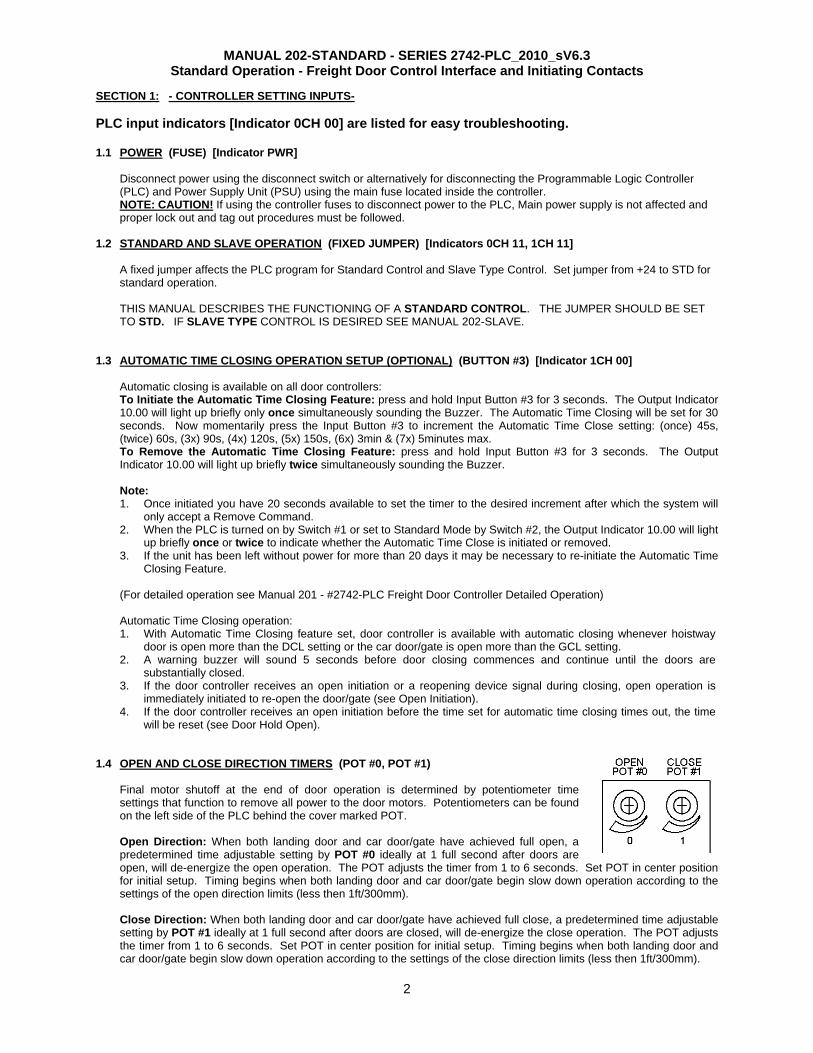
Final motor shutoff at the end of door operation is determined by potentiometer time settings that function to remove all power to the door motors. Potentiometers can be found on the left side of the PLC behind the cover marked POT. Open Direction: When both landing door and car door/gate have achieved full open, a predetermined time adjustable setting by POT #0 ideally at 1 full second after doors are open, will de-energize the open operation. The POT adjusts the timer from 1 to 6 seconds. Set POT in center position for initial setup. Timing begins when both landing door and car door/gate begin slow down operation according to the settings of the open direction limits (less then 1ft/300mm). Close Direction: When both landing door and car door/gate have achieved full close, a predetermined time adjustable setting by POT #1 ideally at 1 full second after doors are closed, will de-energize the close operation. The POT adjusts the timer from 1 to 6 seconds. Set POT in center position for initial setup. Timing begins when both landing door and car door/gate begin slow down operation according to the settings of the close direction limits (less then 1ft/300mm).
MANUAL 202-STANDARD - SERIES 2742-PLC_2010_sV6.3 Standard Operation - Freight Door Control Interface and Initiating Contacts
3
SECTION 2: -ELEVATOR CONTROL INITIATIONS- All contacts are to be dry (voltage free) isolated contacts. PLC input indicators [Indicator 0CH 00] are listed for easy troubleshooting. 2.1 BASIC INITIATIONS: CONTACTS REQUIRED BY THE ELEVATOR CONTROLLER
SPECIFICALLY FOR PEELLE CONTROLLERS #274200 TO #274205:
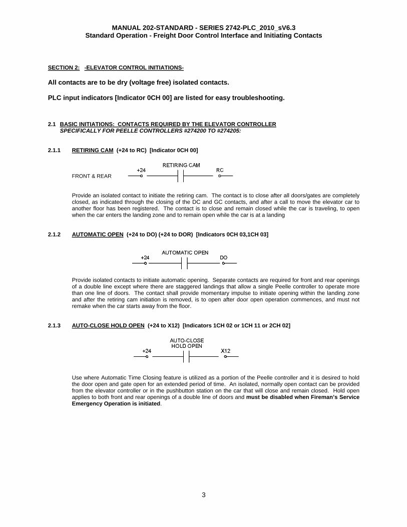
2.1.1 RETIRING CAM (+24 to RC) [Indicator 0CH 00]
FRONT & REAR
Provide an isolated contact to initiate the retiring cam. The contact is to close after all doors/gates are completely closed, as indicated through the closing of the DC and GC contacts, and after a call to move the elevator car to another floor has been registered. The contact is to close and remain closed while the car is traveling, to open when the car enters the landing zone and to remain open while the car is at a landing
2.1.2 AUTOMATIC OPEN (+24 to DO) (+24 to DOR) [Indicators 0CH 03,1CH 03]
Provide isolated contacts to initiate automatic opening. Separate contacts are required for front and rear openings of a double line except where there are staggered landings that allow a single Peelle controller to operate more than one line of doors. The contact shall provide momentary impulse to initiate opening within the landing zone and after the retiring cam initiation is removed, is to open after door open operation commences, and must not remake when the car starts away from the floor.
2.1.3 AUTO-CLOSE HOLD OPEN (+24 to X12) [Indicators 1CH 02 or 1CH 11 or 2CH 02]
Use where Automatic Time Closing feature is utilized as a portion of the Peelle controller and it is desired to hold the door open and gate open for an extended period of time. An isolated, normally open contact can be provided from the elevator controller or in the pushbutton station on the car that will close and remain closed. Hold open applies to both front and rear openings of a double line of doors and must be disabled when Fireman’s Service Emergency Operation is initiated.
MANUAL 202-STANDARD - SERIES 2742-PLC_2010_sV6.3 Standard Operation - Freight Door Control Interface and Initiating Contacts
4
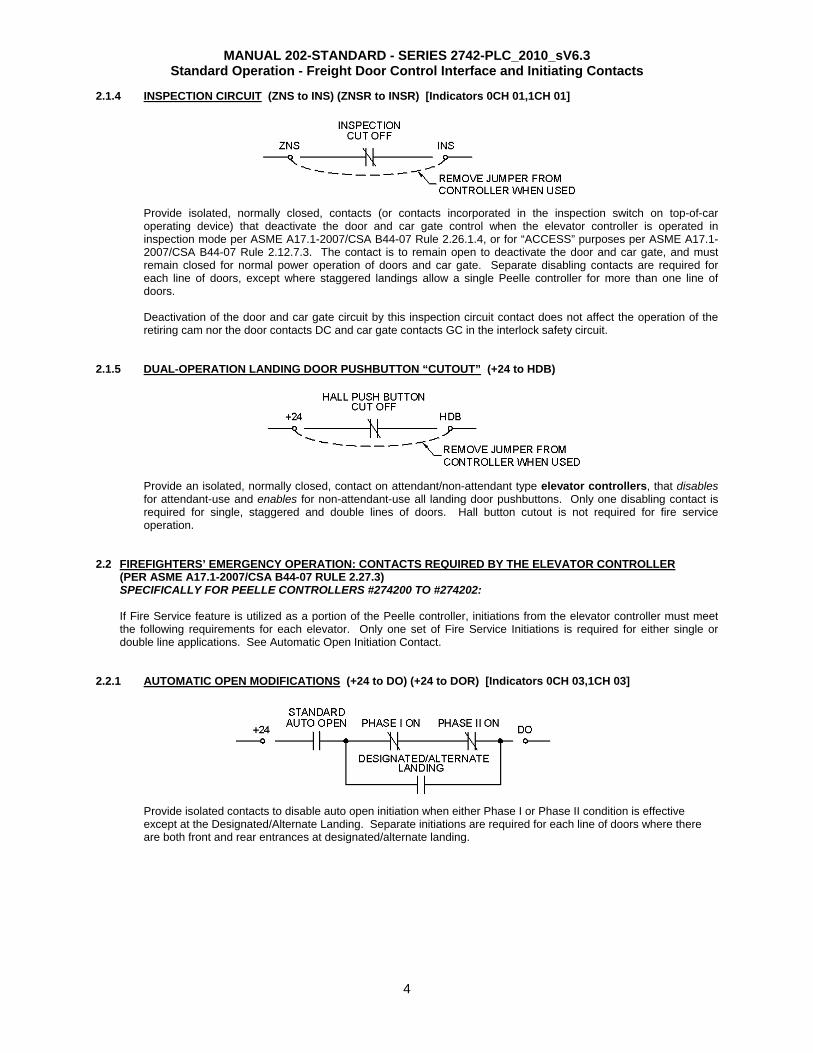
2.1.4 INSPECTION CIRCUIT (ZNS to INS) (ZNSR to INSR) [Indicators 0CH 01,1CH 01]
Provide isolated, normally closed, contacts (or contacts incorporated in the inspection switch on top-of-car operating device) that deactivate the door and car gate control when the elevator controller is operated in inspection mode per ASME A17.1-2007/CSA B44-07 Rule 2.26.1.4, or for “ACCESS” purposes per ASME A17.1-2007/CSA B44-07 Rule 2.12.7.3. The contact is to remain open to deactivate the door and car gate, and must remain closed for normal power operation of doors and car gate. Separate disabling contacts are required for each line of doors, except where staggered landings allow a single Peelle controller for more than one line of doors.
Deactivation of the door and car gate circuit by this inspection circuit contact does not affect the operation of the retiring cam nor the door contacts DC and car gate contacts GC in the interlock safety circuit.
2.1.5 DUAL-OPERATION LANDING DOOR PUSHBUTTON “CUTOUT” (+24 to HDB)
Provide an isolated, normally closed, contact on attendant/non-attendant type elevator controllers, that disables for attendant-use and enables for non-attendant-use all landing door pushbuttons. Only one disabling contact is required for single, staggered and double lines of doors. Hall button cutout is not required for fire service operation.
2.2 FIREFIGHTERS’ EMERGENCY OPERATION: CONTACTS REQUIRED BY THE ELEVATOR CONTROLLER (PER ASME A17.1-2007/CSA B44-07 RULE 2.27.3) SPECIFICALLY FOR PEELLE CONTROLLERS #274200 TO #274202: If Fire Service feature is utilized as a portion of the Peelle controller, initiations from the elevator controller must meet the following requirements for each elevator. Only one set of Fire Service Initiations is required for either single or double line applications. See Automatic Open Initiation Contact.
2.2.1 AUTOMATIC OPEN MODIFICATIONS (+24 to DO) (+24 to DOR) [Indicators 0CH 03,1CH 03]
Provide isolated contacts to disable auto open initiation when either Phase I or Phase II condition is effective except at the Designated/Alternate Landing. Separate initiations are required for each line of doors where there are both front and rear entrances at designated/alternate landing.
MANUAL 202-STANDARD - SERIES 2742-PLC_2010_sV6.3 Standard Operation - Freight Door Control Interface and Initiating Contacts
5
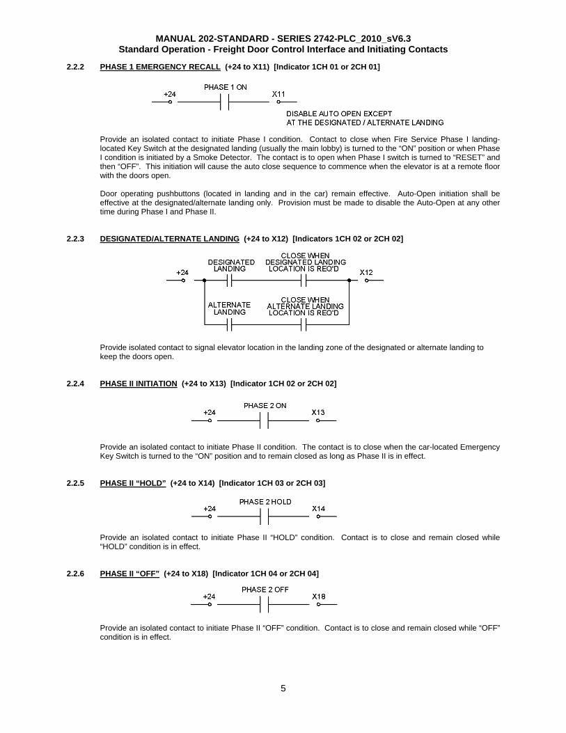
2.2.2 PHASE 1 EMERGENCY RECALL (+24 to X11) [Indicator 1CH 01 or 2CH 01] Provide an isolated contact to initiate Phase I condition. Contact to close when Fire Service Phase I landing-located Key Switch at the designated landing (usually the main lobby) is turned to the “ON” position or when Phase I condition is initiated by a Smoke Detector. The contact is to open when Phase I switch is turned to “RESET” and then “OFF”. This initiation will cause the auto close sequence to commence when the elevator is at a remote floor with the doors open.
Door operating pushbuttons (located in landing and in the car) remain effective. Auto-Open initiation shall be effective at the designated/alternate landing only. Provision must be made to disable the Auto-Open at any other time during Phase I and Phase II.
2.2.3 DESIGNATED/ALTERNATE LANDING (+24 to X12) [Indicators 1CH 02 or 2CH 02]
Provide isolated contact to signal elevator location in the landing zone of the designated or alternate landing to keep the doors open.
2.2.4 PHASE II INITIATION (+24 to X13) [Indicator 1CH 02 or 2CH 02]
Provide an isolated contact to initiate Phase II condition. The contact is to close when the car-located Emergency Key Switch is turned to the “ON” position and to remain closed as long as Phase II is in effect.
2.2.5 PHASE II “HOLD” (+24 to X14) [Indicator 1CH 03 or 2CH 03]
Provide an isolated contact to initiate Phase II “HOLD” condition. Contact is to close and remain closed while “HOLD” condition is in effect.
2.2.6 PHASE II “OFF” (+24 to X18) [Indicator 1CH 04 or 2CH 04]
Provide an isolated contact to initiate Phase II “OFF” condition. Contact is to close and remain closed while “OFF” condition is in effect.
MANUAL 202-STANDARD - SERIES 2742-PLC_2010_sV6.3 Standard Operation - Freight Door Control Interface and Initiating Contacts
6
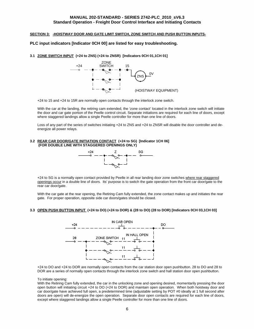
SECTION 3: -HOISTWAY DOOR AND GATE LIMIT SWITCH, ZONE SWITCH AND PUSH BUTTON INPUTS- PLC input indicators [Indicator 0CH 00] are listed for easy troubleshooting. 3.1 ZONE SWITCH INPUT (+24 to ZNS) (+24 to ZNSR) [Indicators 0CH 01,1CH 01]
+24 to 15 and +24 to 15R are normally open contacts through the interlock zone switch. With the car at the landing, the retiring cam extended, the ‘zone contact’ located in the interlock zone switch will initiate the door and car gate portion of the Peelle control circuit. Separate initiations are required for each line of doors, except where staggered landings allow a single Peelle controller for more than one line of doors.
Loss of any part of the series of switches initiating +24 to ZNS and +24 to ZNSR will disable the door controller and de-energize all power relays.
3.2 REAR CAR DOOR/GATE INITIATION CONTACT (+24 to SG) [Indicator 1CH 06]
(FOR DOUBLE LINE WITH STAGGERED OPENINGS ONLY) +24 to SG is a normally open contact provided by Peelle in all rear landing door zone switches where rear staggered openings occur in a double line of doors. Its’ purpose is to switch the gate operation from the front car door/gate to the rear car door/gate. With the car gate at the rear opening, the Retiring Cam fully extended, the zone contact makes up and initiates the rear gate. For proper operation, opposite side car doors/gates should be closed.
3.3 OPEN PUSH BUTTON INPUT (+24 to DO) (+24 to DOR) & (28 to DO) (28 to DOR) [Indicators 0CH 03,1CH 03]
+24 to DO and +24 to DOR are normally open contacts from the car station door open pushbutton. 28 to DO and 28 to DOR are a series of normally open contacts through the interlock zone switch and hall station door open pushbutton. To initiate opening: With the Retiring Cam fully extended, the car in the unlocking zone and opening desired, momentarily pressing the door open button will initiating circuit +24 to DO (+24 to DOR) and maintain open operation. When both hoistway door and car door/gate have achieved full open, a predetermined time (adjustable setting by POT #0 ideally at 1 full second after doors are open) will de-energize the open operation. Separate door open contacts are required for each line of doors, except where staggered landings allow a single Peelle controller for more than one line of doors.
SWITCHZONE
+24
(HOISTWAY EQUIPMENT)
ZNS
15
0V
MANUAL 202-STANDARD - SERIES 2742-PLC_2010_sV6.3 Standard Operation - Freight Door Control Interface and Initiating Contacts
7
A 30 second time protection, built into the controller, times out and de-energizes all open direction relays. Its purpose is to prevent the motors from operating continuously for more than 30 sec. If the time protection times out before the doors are fully open, door operation will not commence until: a) the fault that prevented the doors from fully opening is cleared, and b) a door push button is operated.
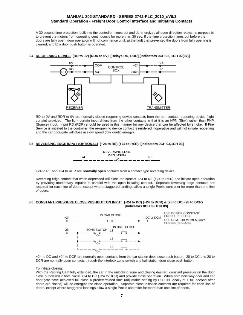
3.4 RE-OPENING DEVICE (RD to 0V) (RDR to 0V) [Relays RD, RDR] [Indicators 0CH 02, 1CH 02(07)]
RD to 0V and RDR to 0V are normally closed reopening device contacts from the non-contact reopening device (light curtain) provided. The light curtain input differs from the other contacts in that it is an NPN (Sink) rather than PNP (Source) input. Input RD (RDR) should be used in this manner for any device that can be affected by smoke. If Fire Service is initiated to the controller, the re-opening device contact is rendered inoperative and will not initiate reopening and the car door/gate will close in slow speed (low kinetic energy).
3.5 REVERSING EDGE INPUT (OPTIONAL) (+24 to RE) (+24 to RER) [Indicators 0CH 03,1CH 03]
+24 to RE and +24 to RER are normally open contacts from a contact type reversing device. Reversing edge contact that when depressed will close the contact +24 to RE (+24 to RER) and initiate open operation by providing momentary impulse in parallel with the open initiating contact. Separate reversing edge contacts are required for each line of doors, except where staggered landings allow a single Peelle controller for more than one line of doors.
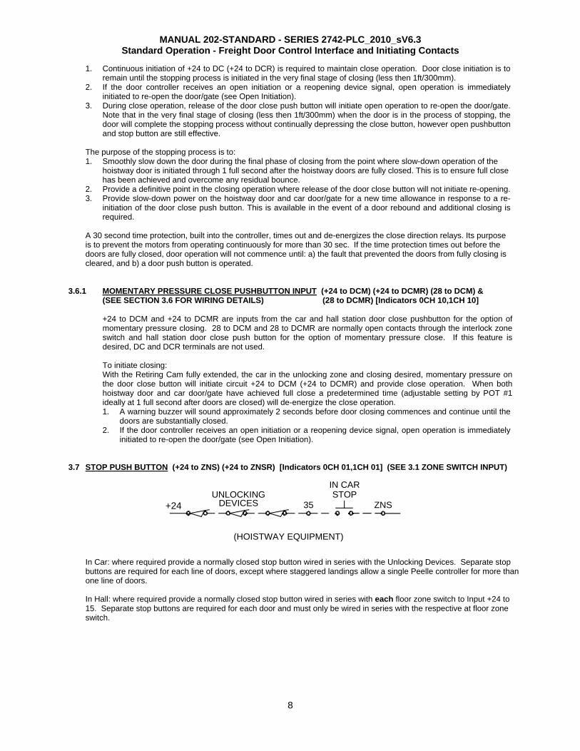
3.6 CONSTANT PRESSURE CLOSE PUSHBUTTON INPUT (+24 to DC) (+24 to DCR) & (28 to DC) (28 to DCR) [Indicators 0CH 09,1CH 09]
+24 to DC and +24 to DCR are normally open contacts from the car station door close push button. 28 to DC and 28 to DCR are normally open contacts through the interlock zone switch and hall station door close push button. To initiate closing: With the Retiring Cam fully extended, the car in the unlocking zone and closing desired, constant pressure on the door close button will initiate circuit +24 to DC (+24 to DCR) and provide close operation. When both hoistway door and car door/gate have achieved full close a predetermined time (adjustable setting by POT #1 ideally at 1 full second after doors are closed) will de-energize the close operation. Separate close initiation contacts are required for each line of doors, except where staggered landings allow a single Peelle controller for more than one line of doors.
28
13
13
IN HALL CLOSE13ZONE SWITCH
+24IN CAR CLOSE
PRESSURE CLOSEUSE DCM FOR MOMENTARY
USE DC FOR CONSTANTPRESSURE CLOSEDC or DCM
RD
0VCOM
RECEIVER TRANSMITTER
N/C
+24+24
GRD0VCONTROL
BOXRD
MANUAL 202-STANDARD - SERIES 2742-PLC_2010_sV6.3 Standard Operation - Freight Door Control Interface and Initiating Contacts
8
1. Continuous initiation of +24 to DC (+24 to DCR) is required to maintain close operation. Door close initiation is to remain until the stopping process is initiated in the very final stage of closing (less then 1ft/300mm).
2. If the door controller receives an open initiation or a reopening device signal, open operation is immediately initiated to re-open the door/gate (see Open Initiation).
3. During close operation, release of the door close push button will initiate open operation to re-open the door/gate. Note that in the very final stage of closing (less then 1ft/300mm) when the door is in the process of stopping, the door will complete the stopping process without continually depressing the close button, however open pushbutton and stop button are still effective.
The purpose of the stopping process is to: 1. Smoothly slow down the door during the final phase of closing from the point where slow-down operation of the
hoistway door is initiated through 1 full second after the hoistway doors are fully closed. This is to ensure full close has been achieved and overcome any residual bounce.
2. Provide a definitive point in the closing operation where release of the door close button will not initiate re-opening. 3. Provide slow-down power on the hoistway door and car door/gate for a new time allowance in response to a re-
initiation of the door close push button. This is available in the event of a door rebound and additional closing is required.
A 30 second time protection, built into the controller, times out and de-energizes the close direction relays. Its purpose is to prevent the motors from operating continuously for more than 30 sec. If the time protection times out before the doors are fully closed, door operation will not commence until: a) the fault that prevented the doors from fully closing is cleared, and b) a door push button is operated.
3.6.1 MOMENTARY PRESSURE CLOSE PUSHBUTTON INPUT (+24 to DCM) (+24 to DCMR) (28 to DCM) & (SEE SECTION 3.6 FOR WIRING DETAILS) (28 to DCMR) [Indicators 0CH 10,1CH 10]
+24 to DCM and +24 to DCMR are inputs from the car and hall station door close pushbutton for the option of momentary pressure closing. 28 to DCM and 28 to DCMR are normally open contacts through the interlock zone switch and hall station door close push button for the option of momentary pressure close. If this feature is desired, DC and DCR terminals are not used. To initiate closing: With the Retiring Cam fully extended, the car in the unlocking zone and closing desired, momentary pressure on the door close button will initiate circuit +24 to DCM (+24 to DCMR) and provide close operation. When both hoistway door and car door/gate have achieved full close a predetermined time (adjustable setting by POT #1 ideally at 1 full second after doors are closed) will de-energize the close operation. 1. A warning buzzer will sound approximately 2 seconds before door closing commences and continue until the
doors are substantially closed. 2. If the door controller receives an open initiation or a reopening device signal, open operation is immediately
initiated to re-open the door/gate (see Open Initiation).
3.7 STOP PUSH BUTTON (+24 to ZNS) (+24 to ZNSR) [Indicators 0CH 01,1CH 01] (SEE 3.1 ZONE SWITCH INPUT)
In Car: where required provide a normally closed stop button wired in series with the Unlocking Devices. Separate stop buttons are required for each line of doors, except where staggered landings allow a single Peelle controller for more than one line of doors. In Hall: where required provide a normally closed stop button wired in series with each floor zone switch to Input +24 to 15. Separate stop buttons are required for each door and must only be wired in series with the respective at floor zone switch.
(HOISTWAY EQUIPMENT)
STOPIN CAR
DEVICESUNLOCKING
35 ZNS+24
MANUAL 202-STANDARD - SERIES 2742-PLC_2010_sV6.3 Standard Operation - Freight Door Control Interface and Initiating Contacts
9
+24
DOL
0VBN (+)DOL
BU (-)
BK (NC)
+24
GOL
0VBN (+)GOL
BU (-)
BK (NC)
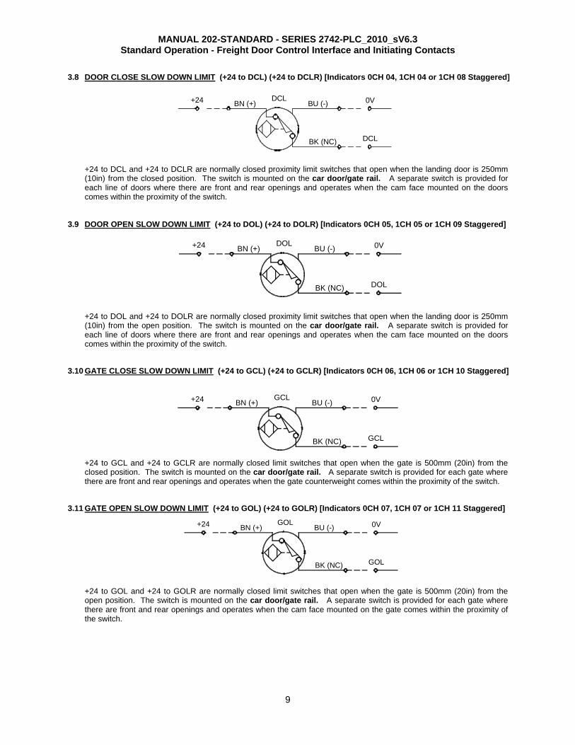
3.8 DOOR CLOSE SLOW DOWN LIMIT (+24 to DCL) (+24 to DCLR) [Indicators 0CH 04, 1CH 04 or 1CH 08 Staggered]
+24 to DCL and +24 to DCLR are normally closed proximity limit switches that open when the landing door is 250mm (10in) from the closed position. The switch is mounted on the car door/gate rail. A separate switch is provided for each line of doors where there are front and rear openings and operates when the cam face mounted on the doors comes within the proximity of the switch.
3.9 DOOR OPEN SLOW DOWN LIMIT (+24 to DOL) (+24 to DOLR) [Indicators 0CH 05, 1CH 05 or 1CH 09 Staggered]
+24 to DOL and +24 to DOLR are normally closed proximity limit switches that open when the landing door is 250mm (10in) from the open position. The switch is mounted on the car door/gate rail. A separate switch is provided for each line of doors where there are front and rear openings and operates when the cam face mounted on the doors comes within the proximity of the switch.
3.10 GATE CLOSE SLOW DOWN LIMIT (+24 to GCL) (+24 to GCLR) [Indicators 0CH 06, 1CH 06 or 1CH 10 Staggered]
+24 to GCL and +24 to GCLR are normally closed limit switches that open when the gate is 500mm (20in) from the closed position. The switch is mounted on the car door/gate rail. A separate switch is provided for each gate where there are front and rear openings and operates when the gate counterweight comes within the proximity of the switch.
3.11 GATE OPEN SLOW DOWN LIMIT (+24 to GOL) (+24 to GOLR) [Indicators 0CH 07, 1CH 07 or 1CH 11 Staggered] +24 to GOL and +24 to GOLR are normally closed limit switches that open when the gate is 500mm (20in) from the open position. The switch is mounted on the car door/gate rail. A separate switch is provided for each gate where there are front and rear openings and operates when the cam face mounted on the gate comes within the proximity of the switch.
BU (-)BN (+)
BK (NC) DCL
+24 DCL 0V
+24
GCL
0VBN (+)GCL
BU (-)
BK (NC)

MANUAL 202-STANDARD - SERIES 2742-PLC_2010_sV6.3 Standard Operation - Freight Door Control Interface and Initiating Contacts
10
3.12 DOOR OPEN FINAL (OPTIONAL) (+24 to DOF) (+24 to DOFR) [Indicators 0CH 08, 1CH 08] Where provided on bi-parting doors, +24 to DOF and +24 to DOFR are normally open limit switches mounted on the Peelle hoistway landing door rail that close when the lower door panel is 13mm (1/2in) from the stop position. A separate switch is provided for each door and wired in parallel to give a hoistway landing door open signal to the door controller. This input is optional and used for the Automatic Stay Open feature on bi-parting doors.
SECTION 4: -OUTPUT SIGNALS AND SAFETY CIRCUIT PROVIDED BY PEELLE- All outputs are dry (voltage free) contacts to the elevator controller. 4.1 CAR DOOR/GATE OPEN FINAL SIGNAL (X15 to X16) (X15R to X16R)
X15 BY PEELLE X16GATE OPEN FINAL
X15 to X16 and X15R to X16R are isolated contacts from gate open final limit GOF and GOFR. Wire switch for either normal open or normally closed as required. A separate signal is provided for each gate to give an open door signal to the elevator controller.
4.2 DOOR AND GATE CLOSED SIGNAL (X19 to X20) (X19R to X20R) [Indicators 10CH 00, 10CH 02] X19 to X20 and X19R to X20R are contacts from the Peelle controller that close when door and car gate close operation is complete. A separate signal is provided for front and rear door close signals to the elevator controller. NOTE: This signal is subject to reset in the event of power failure and should be used for control purposes and redundancy checking only. For interlocking circuit use the door and car gate Interlocking Circuit provided.
MANUAL 202-STANDARD - SERIES 2742-PLC_2010_sV6.3 Standard Operation - Freight Door Control Interface and Initiating Contacts
11
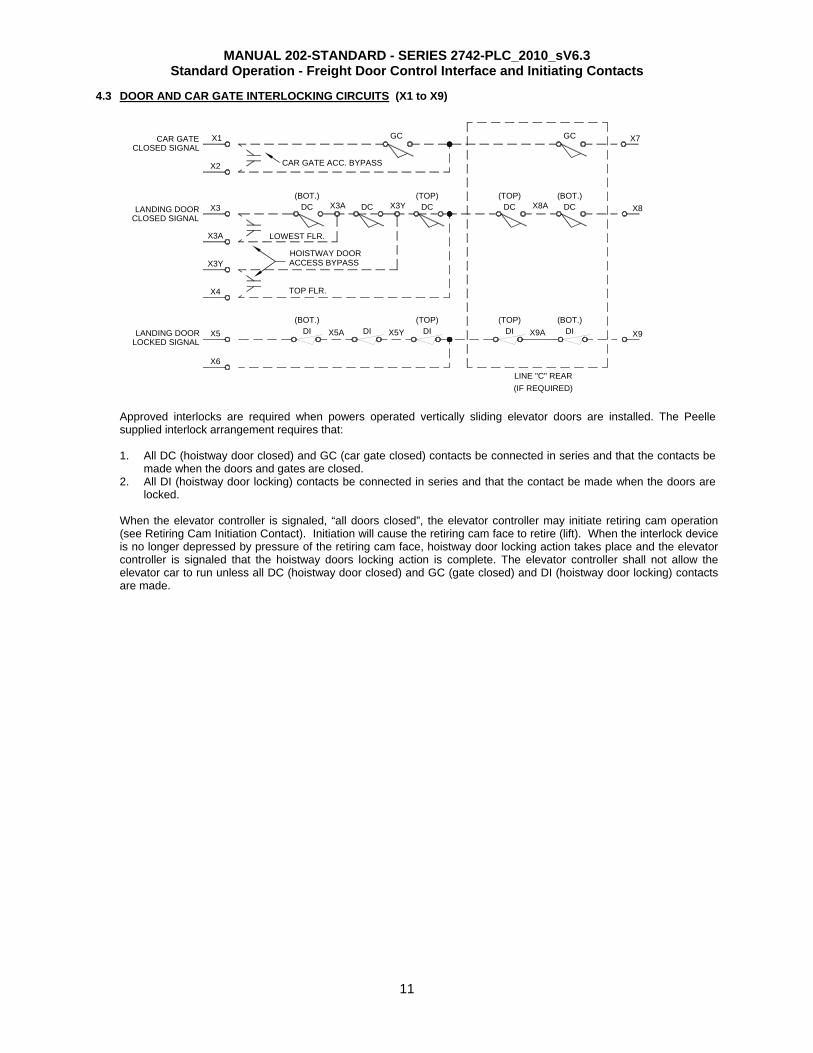
4.3 DOOR AND CAR GATE INTERLOCKING CIRCUITS (X1 to X9)
DC
X1
X2
(TOP)X3YDC DC
GC
(BOT.)
LINE "C" REAR(IF REQUIRED)
DIDI X9A X9
(BOT.)DCDC X8A X8
GC X7
LANDING DOORLOCKED SIGNAL
CLOSED SIGNALLANDING DOOR
CLOSED SIGNALCAR GATE
(TOP)
(TOP)X5AX5
X6
DI(BOT.) (TOP)
X5YDI DI
X3A
HOISTWAY DOORACCESS BYPASS
CAR GATE ACC. BYPASS
(BOT.)X3
X4
X3Y
X3A LOWEST FLR.
TOP FLR.
Approved interlocks are required when powers operated vertically sliding elevator doors are installed. The Peelle supplied interlock arrangement requires that: 1. All DC (hoistway door closed) and GC (car gate closed) contacts be connected in series and that the contacts be
made when the doors and gates are closed. 2. All DI (hoistway door locking) contacts be connected in series and that the contact be made when the doors are
locked.
When the elevator controller is signaled, “all doors closed”, the elevator controller may initiate retiring cam operation (see Retiring Cam Initiation Contact). Initiation will cause the retiring cam face to retire (lift). When the interlock device is no longer depressed by pressure of the retiring cam face, hoistway door locking action takes place and the elevator controller is signaled that the hoistway doors locking action is complete. The elevator controller shall not allow the elevator car to run unless all DC (hoistway door closed) and GC (gate closed) and DI (hoistway door locking) contacts are made.
MANUAL 202-STANDARD - SERIES 2742-PLC_2010_sV6.3 Standard Operation - Freight Door Control Interface and Initiating Contacts
12
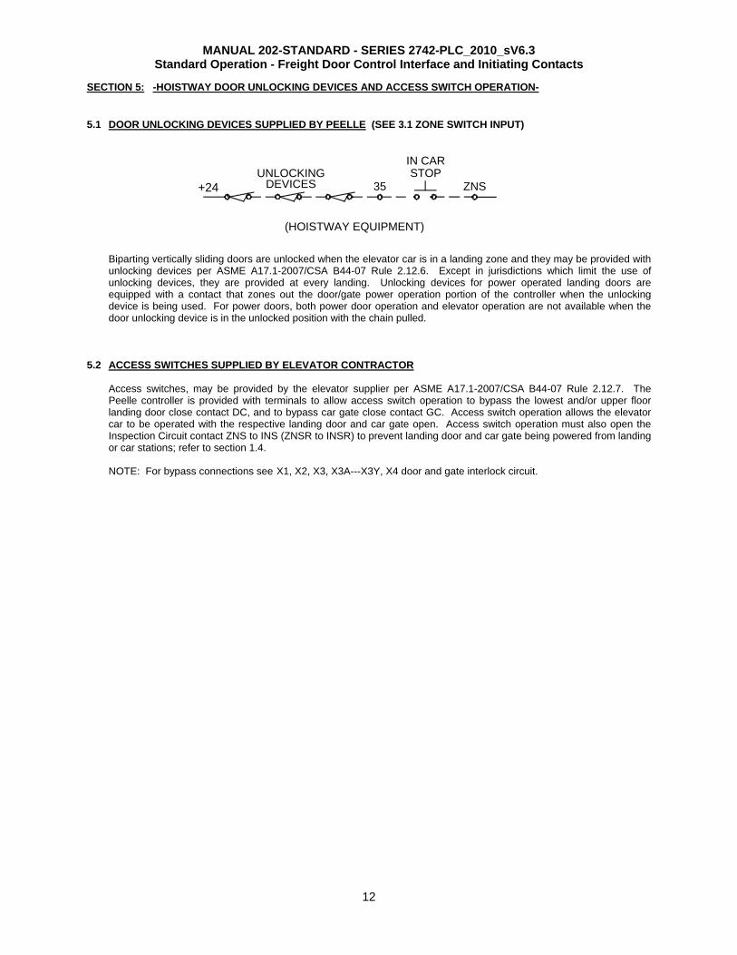
SECTION 5: -HOISTWAY DOOR UNLOCKING DEVICES AND ACCESS SWITCH OPERATION-
5.1 DOOR UNLOCKING DEVICES SUPPLIED BY PEELLE (SEE 3.1 ZONE SWITCH INPUT)
Biparting vertically sliding doors are unlocked when the elevator car is in a landing zone and they may be provided with unlocking devices per ASME A17.1-2007/CSA B44-07 Rule 2.12.6. Except in jurisdictions which limit the use of unlocking devices, they are provided at every landing. Unlocking devices for power operated landing doors are equipped with a contact that zones out the door/gate power operation portion of the controller when the unlocking device is being used. For power doors, both power door operation and elevator operation are not available when the door unlocking device is in the unlocked position with the chain pulled.
5.2 ACCESS SWITCHES SUPPLIED BY ELEVATOR CONTRACTOR Access switches, may be provided by the elevator supplier per ASME A17.1-2007/CSA B44-07 Rule 2.12.7. The Peelle controller is provided with terminals to allow access switch operation to bypass the lowest and/or upper floor landing door close contact DC, and to bypass car gate close contact GC. Access switch operation allows the elevator car to be operated with the respective landing door and car gate open. Access switch operation must also open the Inspection Circuit contact ZNS to INS (ZNSR to INSR) to prevent landing door and car gate being powered from landing or car stations; refer to section 1.4. NOTE: For bypass connections see X1, X2, X3, X3A---X3Y, X4 door and gate interlock circuit.
(HOISTWAY EQUIPMENT)
STOPIN CAR
DEVICESUNLOCKING
35 ZNS+24
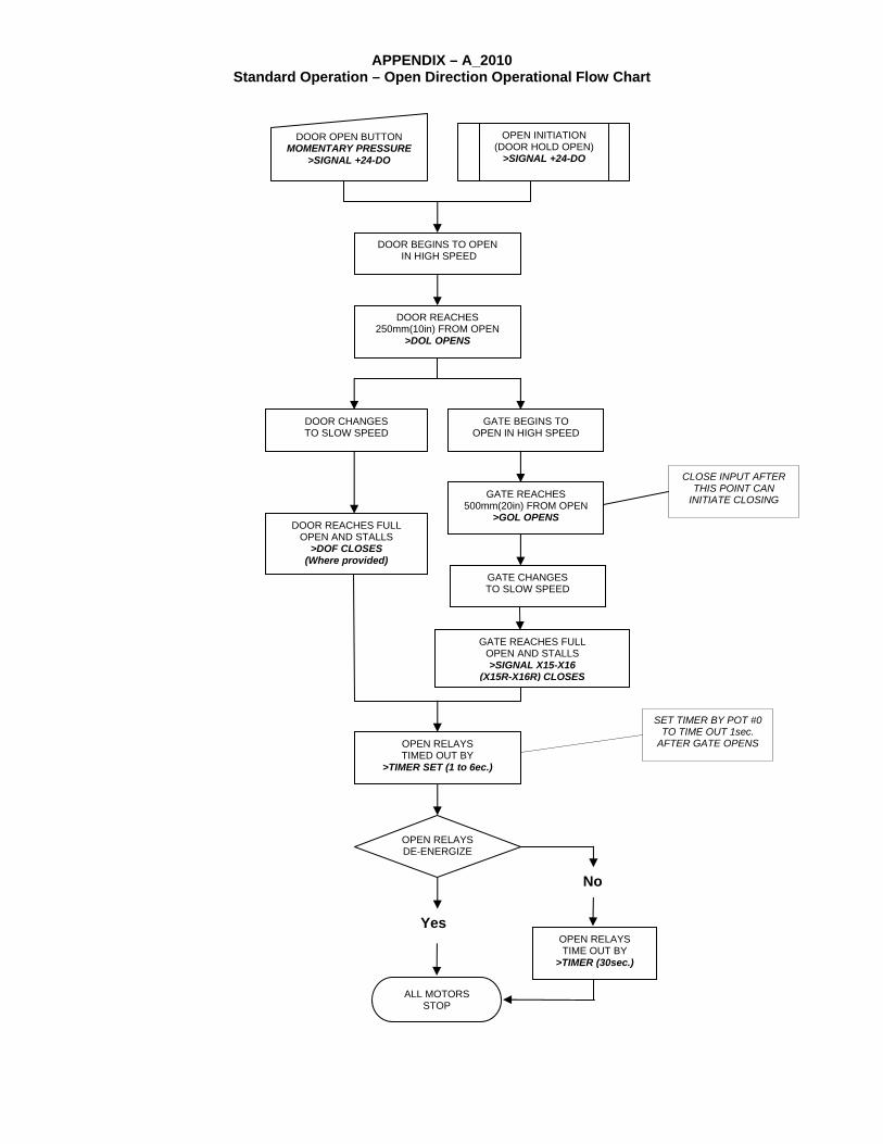
APPENDIX – A_2010 Standard Operation – Open Direction Operational Flow Chart
DOOR BEGINS TO OPEN IN HIGH SPEED
DOOR REACHES 250mm(10in) FROM OPEN
>DOL OPENS
DOOR CHANGES TO SLOW SPEED
GATE BEGINS TO OPEN IN HIGH SPEED
DOOR REACHES FULL OPEN AND STALLS
>DOF CLOSES (Where provided)
GATE REACHES 500mm(20in) FROM OPEN
>GOL OPENS
GATE CHANGES TO SLOW SPEED
GATE REACHES FULL OPEN AND STALLS >SIGNAL X15-X16
(X15R-X16R) CLOSES
OPEN RELAYS DE-ENERGIZE
No
ALL MOTORS STOP
Yes OPEN RELAYS TIME OUT BY
>TIMER (30sec.)
DOOR OPEN BUTTON MOMENTARY PRESSURE
>SIGNAL +24-DO
OPEN INITIATION (DOOR HOLD OPEN)
>SIGNAL +24-DO
OPEN RELAYS TIMED OUT BY
>TIMER SET (1 to 6ec.)
SET TIMER BY POT #0 TO TIME OUT 1sec.
AFTER GATE OPENS
CLOSE INPUT AFTER THIS POINT CAN
INITIATE CLOSING

APPENDIX – A_2010 Standard Operation – Close Direction Operational Flow Chart
GATE BEGINS TO CLOSE IN HIGH SPEED
GATE REACHES 500mm(20in) FROM CLOSE
>GCL OPENS
GATE CHANGES TO SLOW SPEED
DOOR BEGINS TO CLOSE IN HIGH SPEED
GATE REACHES CLOSE AND STALLS
>SAFETY SIGNAL X1-X2 (X2-X7) CLOSES
DOOR REACHES 250mm(10in) FROM CLOSE
>DCL OPENS
DOOR CHANGES TO SLOW SPEED
DOOR REACHES FULL CLOSE AND STALLS
>SAFETY SIGNAL X3-X4 (X4-X8) CLOSES
CLOSE RELAYS DE-ENERGIZE
No
ALL MOTORS STOP
Yes CLOSE RELAYS
TIME OUT BY >TIMER (30sec.)
DOOR CLOSE BUTTON CONTINUOUS PRESSURE
>SIGNAL +24-DC
FIREFIGHTERS PHASE 1 RECALL >SIGNAL +24-X11
WARNING SIGNAL (5sec. Auto-close) (1sec. Momentary)
>OUTPUT BUZZER
GATE MOTOR TIMED OUT BY >TIMER (6sec.)
CLOSE RELAYS TIMED OUT BY
>TIMER SET (1 to 6sec.) >SIGNAL X19-X20 (X19R-X20R)
CLOSES
ENGAGEMENT OF REOPENING DEVICE BEFORE
THIS POINT WILL INITIATE RE-OPENING
PHASE 1 RECALL REOPENING
DEVICE RENDERED INOPERATIVE
RELEASE OF CLOSE BUTTON BEFORE THIS POINT WILL INITIATE
RE-OPENING
SET TIMER BY POT #1 TO TIME OUT 1sec.
AFTER DOOR CLOSES TO PREVENT BOUNCE
PHASE 1 RECALL ONLY
GATE CHANGES TO SLOW SPEED BY >TIMER (1sec.)
GATE REMAINS IN SLOW SPEED DURING PHASE 1
RECALL
DOOR CLOSE BUTTON MOMENTARY PRESSURE
>SIGNAL +24-DCM
AUTO-CLOSE >TIMER SET 30, 45, 60, 90, 120, 150, 180, 300
seconds FOR HOLD OPEN >SIGNAL +24-X12

ON
STA
TEO
N F
OR
MO
ME
NTA
RY
/ A
UTO
MA
TIC
CLO
SE
A
ON
FO
R S
LOW
SP
EE
D C
AR
DO
OR
OP
ER
ATI
ON
SO
N F
OR
SIM
ULT
AN
EO
US
OP
ER
ATI
ON
F
Sig
nal
Nam
eFr
ont
Indi
cato
r
Rea
r Doo
r In
dica
tor
Dou
ble
Line
Lift
Trav
elin
g B
etw
een
Floo
rs
Lift
Arr
ives
at
Flo
orD
oors
Fin
al
Ope
ning
Doo
rs F
ully
O
pen
Mom
enta
ry/
Aut
oclo
seD
oors
Fin
al
Clo
sing
Doo
rs F
ully
C
lose
d
RC
0CH
00
ZNS
0CH
01
1CH
01
SE
0CH
02
1CH
02
DO
0CH
03
1CH
03
DC
L0C
H 0
41C
H 0
4D
OL
0CH
05
1CH
05
GC
L0C
H 0
61C
H 0
6G
OL
0CH
07
1CH
07
DO
F0C
H 0
81C
H 0
8D
C0C
H 0
91C
H 0
9D
CM
0CH
10
1CH
10
AS
LA0C
H 1
1B
UZ
10C
H 0
2A
RC
R10
CH
03
O10
CH
04
11C
H 0
2C
10C
H 0
511
CH
03
DH
10C
H 0
611
CH
04
DL
10C
H 0
711
CH
05
GH
11C
H 0
011
CH
06
GL
11C
H 0
111
CH
07
X15
-X16
X19
-X20
10C
H 0
010
CH
01
GC
(X1-
X2)
(X2-
X7)
DC
(X3-
X4)
(X4-
X8)
DI
(X5-
X6)
(X6-
X9)
Inpu
ts a
nd
Initi
atio
ns
Inte
rlock
Sig
nals
PLC
O
utpu
ts to
C
ontro
l R
elay
s
APP
END
IX -
B_2
010
Stan
dard
Ope
ratio
n Tr
oubl
esho
otin
g C
hart
AA
Sta
ndar
d
Land
ing
Doo
r O
peni
ngC
ar D
oor
Ope
ning
Car
Doo
r C
losi
ngLa
ndin
g D
oor
Clo
sing
I/O F
unct
ion
Cha
rt-U
se th
e ap
prop
riate
cha
rt fo
r STA
ND
AR
D o
r SLA
VE
ope
ratio
nal i
nter
face
-ZN
S m
ust b
e O
N to
allo
w d
oor o
pera
tion
and
goes
OFF
whe
n re
tirin
g ca
m is
lifte
d.-In
seq
uenc
e op
en, t
he c
ar d
oor w
ill n
ot s
tart
to o
pen
until
the
land
ing
door
is 2
/3 o
pen.
-In s
eque
nce
clos
e, th
e la
ndin
g do
or w
ill n
ot s
tart
to c
lose
unt
il th
e ca
r doo
r is
2/3
clos
ed-D
C, c
onst
ant p
ress
ure
door
clo
se b
e he
ld u
ntil
both
car
and
land
ing
door
s ar
e cl
osed
.
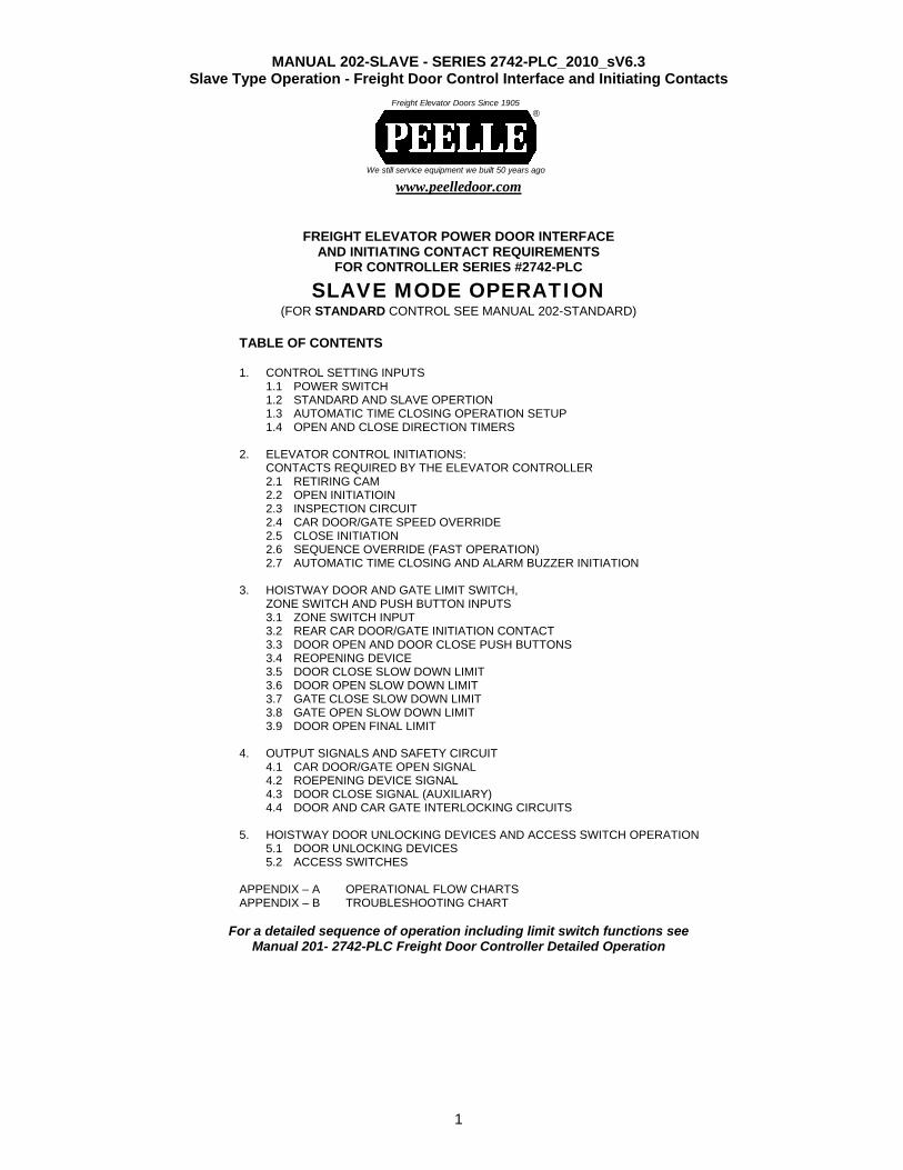
MANUAL 202-SLAVE - SERIES 2742-PLC_2010_sV6.3 Slave Type Operation - Freight Door Control Interface and Initiating Contacts
1
www.peelledoor.com
FREIGHT ELEVATOR POWER DOOR INTERFACE
AND INITIATING CONTACT REQUIREMENTS FOR CONTROLLER SERIES #2742-PLC
SLAVE MODE OPERATION (FOR STANDARD CONTROL SEE MANUAL 202-STANDARD)
TABLE OF CONTENTS 1. CONTROL SETTING INPUTS
1.1 POWER SWITCH 1.2 STANDARD AND SLAVE OPERTION 1.3 AUTOMATIC TIME CLOSING OPERATION SETUP 1.4 OPEN AND CLOSE DIRECTION TIMERS
2. ELEVATOR CONTROL INITIATIONS: CONTACTS REQUIRED BY THE ELEVATOR CONTROLLER 2.1 RETIRING CAM 2.2 OPEN INITIATIOIN 2.3 INSPECTION CIRCUIT 2.4 CAR DOOR/GATE SPEED OVERRIDE 2.5 CLOSE INITIATION 2.6 SEQUENCE OVERRIDE (FAST OPERATION) 2.7 AUTOMATIC TIME CLOSING AND ALARM BUZZER INITIATION
3. HOISTWAY DOOR AND GATE LIMIT SWITCH, ZONE SWITCH AND PUSH BUTTON INPUTS 3.1 ZONE SWITCH INPUT 3.2 REAR CAR DOOR/GATE INITIATION CONTACT 3.3 DOOR OPEN AND DOOR CLOSE PUSH BUTTONS 3.4 REOPENING DEVICE 3.5 DOOR CLOSE SLOW DOWN LIMIT 3.6 DOOR OPEN SLOW DOWN LIMIT 3.7 GATE CLOSE SLOW DOWN LIMIT 3.8 GATE OPEN SLOW DOWN LIMIT 3.9 DOOR OPEN FINAL LIMIT
4. OUTPUT SIGNALS AND SAFETY CIRCUIT 4.1 CAR DOOR/GATE OPEN SIGNAL 4.2 ROEPENING DEVICE SIGNAL 4.3 DOOR CLOSE SIGNAL (AUXILIARY) 4.4 DOOR AND CAR GATE INTERLOCKING CIRCUITS
5. HOISTWAY DOOR UNLOCKING DEVICES AND ACCESS SWITCH OPERATION 5.1 DOOR UNLOCKING DEVICES 5.2 ACCESS SWITCHES
APPENDIX – A OPERATIONAL FLOW CHARTS APPENDIX – B TROUBLESHOOTING CHART
For a detailed sequence of operation including limit switch functions see Manual 201- 2742-PLC Freight Door Controller Detailed Operation
We still service equipment we built 50 years ago
Freight Elevator Doors Since 1905 ®
MANUAL 202-SLAVE - SERIES 2742-PLC_2010_sV6.3 Slave Operation - Freight Door Control Interface and Initiating Contacts
2
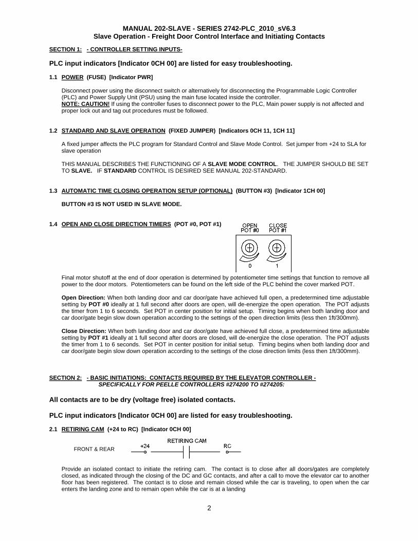
SECTION 1: - CONTROLLER SETTING INPUTS- PLC input indicators [Indicator 0CH 00] are listed for easy troubleshooting. 1.1 POWER (FUSE) [Indicator PWR]
Disconnect power using the disconnect switch or alternatively for disconnecting the Programmable Logic Controller (PLC) and Power Supply Unit (PSU) using the main fuse located inside the controller. NOTE: CAUTION! If using the controller fuses to disconnect power to the PLC, Main power supply is not affected and proper lock out and tag out procedures must be followed.
1.2 STANDARD AND SLAVE OPERATION (FIXED JUMPER) [Indicators 0CH 11, 1CH 11]
A fixed jumper affects the PLC program for Standard Control and Slave Mode Control. Set jumper from +24 to SLA for slave operation THIS MANUAL DESCRIBES THE FUNCTIONING OF A SLAVE MODE CONTROL. THE JUMPER SHOULD BE SET TO SLAVE. IF STANDARD CONTROL IS DESIRED SEE MANUAL 202-STANDARD.
1.3 AUTOMATIC TIME CLOSING OPERATION SETUP (OPTIONAL) (BUTTON #3) [Indicator 1CH 00]
BUTTON #3 IS NOT USED IN SLAVE MODE. 1.4 OPEN AND CLOSE DIRECTION TIMERS (POT #0, POT #1)
Final motor shutoff at the end of door operation is determined by potentiometer time settings that function to remove all power to the door motors. Potentiometers can be found on the left side of the PLC behind the cover marked POT. Open Direction: When both landing door and car door/gate have achieved full open, a predetermined time adjustable setting by POT #0 ideally at 1 full second after doors are open, will de-energize the open operation. The POT adjusts the timer from 1 to 6 seconds. Set POT in center position for initial setup. Timing begins when both landing door and car door/gate begin slow down operation according to the settings of the open direction limits (less then 1ft/300mm). Close Direction: When both landing door and car door/gate have achieved full close, a predetermined time adjustable setting by POT #1 ideally at 1 full second after doors are closed, will de-energize the close operation. The POT adjusts the timer from 1 to 6 seconds. Set POT in center position for initial setup. Timing begins when both landing door and car door/gate begin slow down operation according to the settings of the close direction limits (less then 1ft/300mm).
SECTION 2: - BASIC INITIATIONS: CONTACTS REQUIRED BY THE ELEVATOR CONTROLLER -
SPECIFICALLY FOR PEELLE CONTROLLERS #274200 TO #274205: All contacts are to be dry (voltage free) isolated contacts. PLC input indicators [Indicator 0CH 00] are listed for easy troubleshooting. 2.1 RETIRING CAM (+24 to RC) [Indicator 0CH 00]
FRONT & REAR
Provide an isolated contact to initiate the retiring cam. The contact is to close after all doors/gates are completely closed, as indicated through the closing of the DC and GC contacts, and after a call to move the elevator car to another floor has been registered. The contact is to close and remain closed while the car is traveling, to open when the car enters the landing zone and to remain open while the car is at a landing
MANUAL 202-SLAVE - SERIES 2742-PLC_2010_sV6.3 Slave Operation - Freight Door Control Interface and Initiating Contacts
3
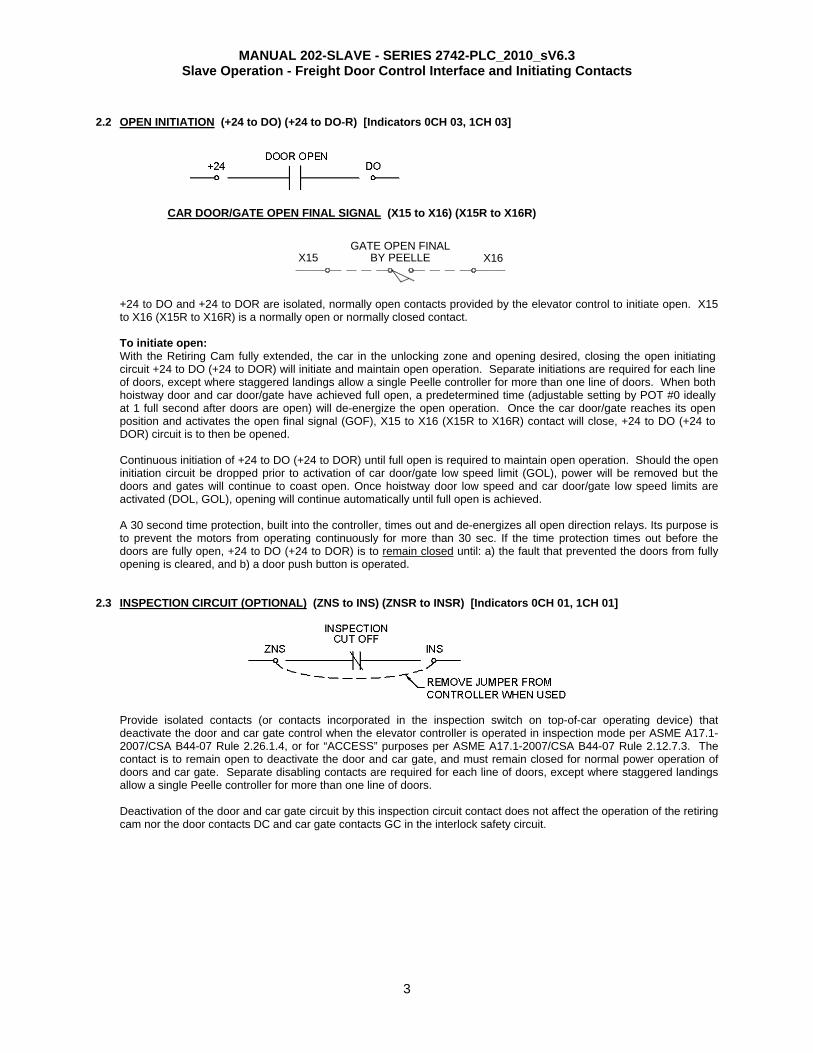
2.2 OPEN INITIATION (+24 to DO) (+24 to DO-R) [Indicators 0CH 03, 1CH 03]
CAR DOOR/GATE OPEN FINAL SIGNAL (X15 to X16) (X15R to X16R)
+24 to DO and +24 to DOR are isolated, normally open contacts provided by the elevator control to initiate open. X15 to X16 (X15R to X16R) is a normally open or normally closed contact. To initiate open: With the Retiring Cam fully extended, the car in the unlocking zone and opening desired, closing the open initiating circuit +24 to DO (+24 to DOR) will initiate and maintain open operation. Separate initiations are required for each line of doors, except where staggered landings allow a single Peelle controller for more than one line of doors. When both hoistway door and car door/gate have achieved full open, a predetermined time (adjustable setting by POT #0 ideally at 1 full second after doors are open) will de-energize the open operation. Once the car door/gate reaches its open position and activates the open final signal (GOF), X15 to X16 (X15R to X16R) contact will close, +24 to DO (+24 to DOR) circuit is to then be opened. Continuous initiation of +24 to DO (+24 to DOR) until full open is required to maintain open operation. Should the open initiation circuit be dropped prior to activation of car door/gate low speed limit (GOL), power will be removed but the doors and gates will continue to coast open. Once hoistway door low speed and car door/gate low speed limits are activated (DOL, GOL), opening will continue automatically until full open is achieved. A 30 second time protection, built into the controller, times out and de-energizes all open direction relays. Its purpose is to prevent the motors from operating continuously for more than 30 sec. If the time protection times out before the doors are fully open, +24 to DO (+24 to DOR) is to remain closed until: a) the fault that prevented the doors from fully opening is cleared, and b) a door push button is operated.
2.3 INSPECTION CIRCUIT (OPTIONAL) (ZNS to INS) (ZNSR to INSR) [Indicators 0CH 01, 1CH 01]
Provide isolated contacts (or contacts incorporated in the inspection switch on top-of-car operating device) that deactivate the door and car gate control when the elevator controller is operated in inspection mode per ASME A17.1-2007/CSA B44-07 Rule 2.26.1.4, or for “ACCESS” purposes per ASME A17.1-2007/CSA B44-07 Rule 2.12.7.3. The contact is to remain open to deactivate the door and car gate, and must remain closed for normal power operation of doors and car gate. Separate disabling contacts are required for each line of doors, except where staggered landings allow a single Peelle controller for more than one line of doors. Deactivation of the door and car gate circuit by this inspection circuit contact does not affect the operation of the retiring cam nor the door contacts DC and car gate contacts GC in the interlock safety circuit.
X15 BY PEELLEGATE OPEN FINAL
X16
MANUAL 202-SLAVE - SERIES 2742-PLC_2010_sV6.3 Slave Operation - Freight Door Control Interface and Initiating Contacts
4
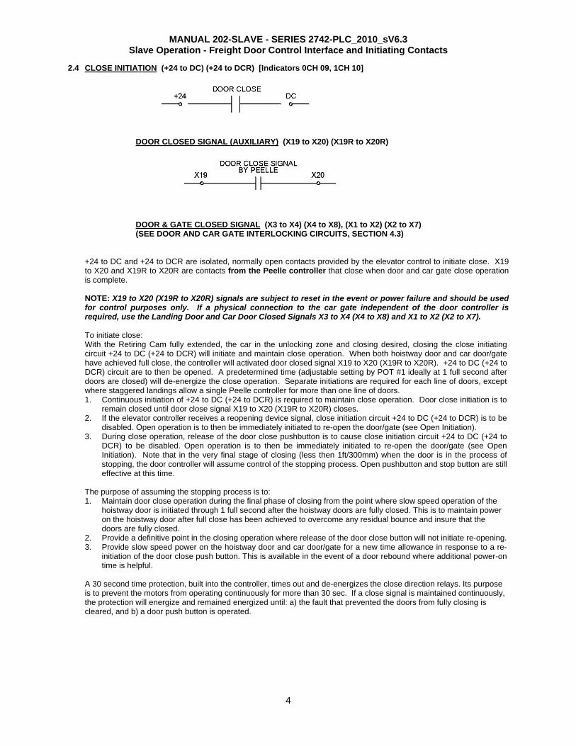
2.4 CLOSE INITIATION (+24 to DC) (+24 to DCR) [Indicators 0CH 09, 1CH 10]
DOOR CLOSED SIGNAL (AUXILIARY) (X19 to X20) (X19R to X20R)
DOOR & GATE CLOSED SIGNAL (X3 to X4) (X4 to X8), (X1 to X2) (X2 to X7) (SEE DOOR AND CAR GATE INTERLOCKING CIRCUITS, SECTION 4.3)
+24 to DC and +24 to DCR are isolated, normally open contacts provided by the elevator control to initiate close. X19 to X20 and X19R to X20R are contacts from the Peelle controller that close when door and car gate close operation is complete. NOTE: X19 to X20 (X19R to X20R) signals are subject to reset in the event or power failure and should be used for control purposes only. If a physical connection to the car gate independent of the door controller is required, use the Landing Door and Car Door Closed Signals X3 to X4 (X4 to X8) and X1 to X2 (X2 to X7). To initiate close: With the Retiring Cam fully extended, the car in the unlocking zone and closing desired, closing the close initiating circuit +24 to DC (+24 to DCR) will initiate and maintain close operation. When both hoistway door and car door/gate have achieved full close, the controller will activated door closed signal X19 to X20 (X19R to X20R). +24 to DC (+24 to DCR) circuit are to then be opened. A predetermined time (adjustable setting by POT #1 ideally at 1 full second after doors are closed) will de-energize the close operation. Separate initiations are required for each line of doors, except where staggered landings allow a single Peelle controller for more than one line of doors. 1. Continuous initiation of +24 to DC (+24 to DCR) is required to maintain close operation. Door close initiation is to
remain closed until door close signal X19 to X20 (X19R to X20R) closes. 2. If the elevator controller receives a reopening device signal, close initiation circuit +24 to DC (+24 to DCR) is to be
disabled. Open operation is to then be immediately initiated to re-open the door/gate (see Open Initiation). 3. During close operation, release of the door close pushbutton is to cause close initiation circuit +24 to DC (+24 to
DCR) to be disabled. Open operation is to then be immediately initiated to re-open the door/gate (see Open Initiation). Note that in the very final stage of closing (less then 1ft/300mm) when the door is in the process of stopping, the door controller will assume control of the stopping process. Open pushbutton and stop button are still effective at this time.
The purpose of assuming the stopping process is to: 1. Maintain door close operation during the final phase of closing from the point where slow speed operation of the
hoistway door is initiated through 1 full second after the hoistway doors are fully closed. This is to maintain power on the hoistway door after full close has been achieved to overcome any residual bounce and insure that the doors are fully closed.
2. Provide a definitive point in the closing operation where release of the door close button will not initiate re-opening. 3. Provide slow speed power on the hoistway door and car door/gate for a new time allowance in response to a re-
initiation of the door close push button. This is available in the event of a door rebound where additional power-on time is helpful.
A 30 second time protection, built into the controller, times out and de-energizes the close direction relays. Its purpose is to prevent the motors from operating continuously for more than 30 sec. If a close signal is maintained continuously, the protection will energize and remained energized until: a) the fault that prevented the doors from fully closing is cleared, and b) a door push button is operated.
MANUAL 202-SLAVE - SERIES 2742-PLC_2010_sV6.3 Slave Operation - Freight Door Control Interface and Initiating Contacts
5
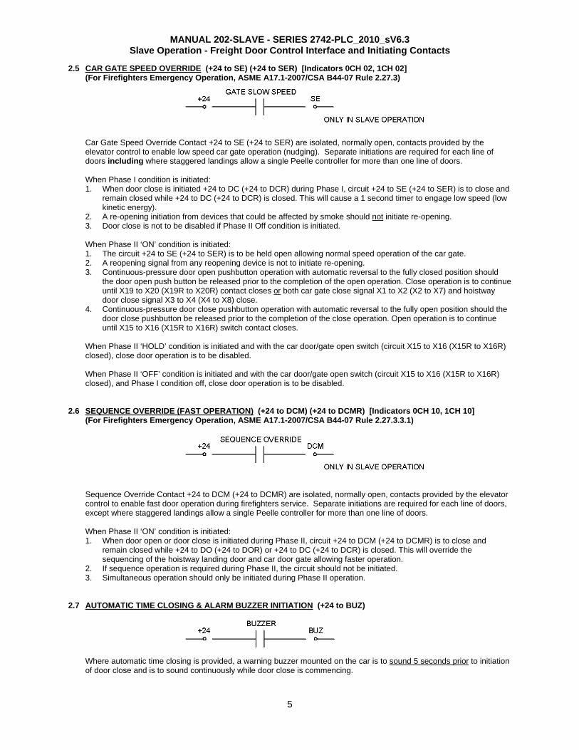
2.5 CAR GATE SPEED OVERRIDE (+24 to SE) (+24 to SER) [Indicators 0CH 02, 1CH 02] (For Firefighters Emergency Operation, ASME A17.1-2007/CSA B44-07 Rule 2.27.3)
Car Gate Speed Override Contact +24 to SE (+24 to SER) are isolated, normally open, contacts provided by the elevator control to enable low speed car gate operation (nudging). Separate initiations are required for each line of doors including where staggered landings allow a single Peelle controller for more than one line of doors.
When Phase I condition is initiated: 1. When door close is initiated +24 to DC (+24 to DCR) during Phase I, circuit +24 to SE (+24 to SER) is to close and
remain closed while +24 to DC (+24 to DCR) is closed. This will cause a 1 second timer to engage low speed (low kinetic energy).
2. A re-opening initiation from devices that could be affected by smoke should not initiate re-opening. 3. Door close is not to be disabled if Phase II Off condition is initiated.
When Phase II ‘ON’ condition is initiated: 1. The circuit +24 to SE (+24 to SER) is to be held open allowing normal speed operation of the car gate. 2. A reopening signal from any reopening device is not to initiate re-opening. 3. Continuous-pressure door open pushbutton operation with automatic reversal to the fully closed position should
the door open push button be released prior to the completion of the open operation. Close operation is to continue until X19 to X20 (X19R to X20R) contact closes or both car gate close signal X1 to X2 (X2 to X7) and hoistway door close signal X3 to X4 (X4 to X8) close.
4. Continuous-pressure door close pushbutton operation with automatic reversal to the fully open position should the door close pushbutton be released prior to the completion of the close operation. Open operation is to continue until X15 to X16 (X15R to X16R) switch contact closes.
When Phase II ‘HOLD’ condition is initiated and with the car door/gate open switch (circuit X15 to X16 (X15R to X16R) closed), close door operation is to be disabled.
When Phase II ‘OFF’ condition is initiated and with the car door/gate open switch (circuit X15 to X16 (X15R to X16R) closed), and Phase I condition off, close door operation is to be disabled.
2.6 SEQUENCE OVERRIDE (FAST OPERATION) (+24 to DCM) (+24 to DCMR) [Indicators 0CH 10, 1CH 10]
(For Firefighters Emergency Operation, ASME A17.1-2007/CSA B44-07 Rule 2.27.3.3.1)
Sequence Override Contact +24 to DCM (+24 to DCMR) are isolated, normally open, contacts provided by the elevator control to enable fast door operation during firefighters service. Separate initiations are required for each line of doors, except where staggered landings allow a single Peelle controller for more than one line of doors.
When Phase II ‘ON’ condition is initiated: 1. When door open or door close is initiated during Phase II, circuit +24 to DCM (+24 to DCMR) is to close and
remain closed while +24 to DO (+24 to DOR) or +24 to DC (+24 to DCR) is closed. This will override the sequencing of the hoistway landing door and car door gate allowing faster operation.
2. If sequence operation is required during Phase II, the circuit should not be initiated. 3. Simultaneous operation should only be initiated during Phase II operation.
2.7 AUTOMATIC TIME CLOSING & ALARM BUZZER INITIATION (+24 to BUZ)
Where automatic time closing is provided, a warning buzzer mounted on the car is to sound 5 seconds prior to initiation of door close and is to sound continuously while door close is commencing.
MANUAL 202-SLAVE - SERIES 2742-PLC_2010_sV6.3 Slave Operation - Freight Door Control Interface and Initiating Contacts
6
The minimum time allowance before closing is initiated should be 30 seconds. Freight type handling requires longer loading/unloading time then passenger elevators. Reduced automatic time closing allowance will result in excessive and unnecessary cycling of the door operating system and premature wear. When the alarm buzzer is required for automatic closing, the elevator control is to provide isolated normally open initiation contacts COM to BUZ that when closed, will sound the buzzer.
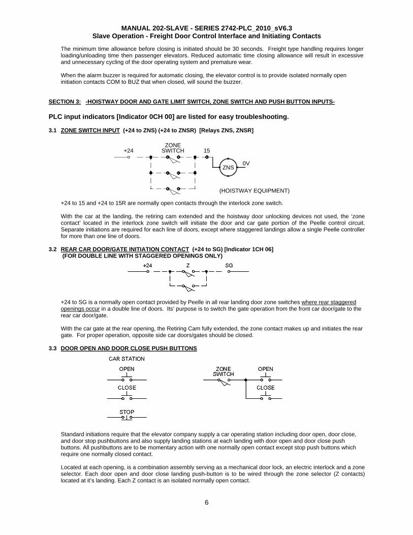
SECTION 3: -HOISTWAY DOOR AND GATE LIMIT SWITCH, ZONE SWITCH AND PUSH BUTTON INPUTS- PLC input indicators [Indicator 0CH 00] are listed for easy troubleshooting. 3.1 ZONE SWITCH INPUT (+24 to ZNS) (+24 to ZNSR) [Relays ZNS, ZNSR]
+24 to 15 and +24 to 15R are normally open contacts through the interlock zone switch. With the car at the landing, the retiring cam extended and the hoistway door unlocking devices not used, the ‘zone contact’ located in the interlock zone switch will initiate the door and car gate portion of the Peelle control circuit. Separate initiations are required for each line of doors, except where staggered landings allow a single Peelle controller for more than one line of doors.
3.2 REAR CAR DOOR/GATE INITIATION CONTACT (+24 to SG) [Indicator 1CH 06]
(FOR DOUBLE LINE WITH STAGGERED OPENINGS ONLY) +24 to SG is a normally open contact provided by Peelle in all rear landing door zone switches where rear staggered openings occur in a double line of doors. Its’ purpose is to switch the gate operation from the front car door/gate to the rear car door/gate. With the car gate at the rear opening, the Retiring Cam fully extended, the zone contact makes up and initiates the rear gate. For proper operation, opposite side car doors/gates should be closed.
3.3 DOOR OPEN AND DOOR CLOSE PUSH BUTTONS
Standard initiations require that the elevator company supply a car operating station including door open, door close, and door stop pushbuttons and also supply landing stations at each landing with door open and door close push buttons. All pushbuttons are to be momentary action with one normally open contact except stop push buttons which require one normally closed contact.
Located at each opening, is a combination assembly serving as a mechanical door lock, an electric interlock and a zone selector. Each door open and door close landing push-button is to be wired through the zone selector (Z contacts) located at it’s landing. Each Z contact is an isolated normally open contact.
SWITCHZONE
+24
(HOISTWAY EQUIPMENT)
ZNS
15
0V
MANUAL 202-SLAVE - SERIES 2742-PLC_2010_sV6.3 Slave Operation - Freight Door Control Interface and Initiating Contacts
7
+24
DOL
0VBN (+)DOL
BU (-)
BK (NC)
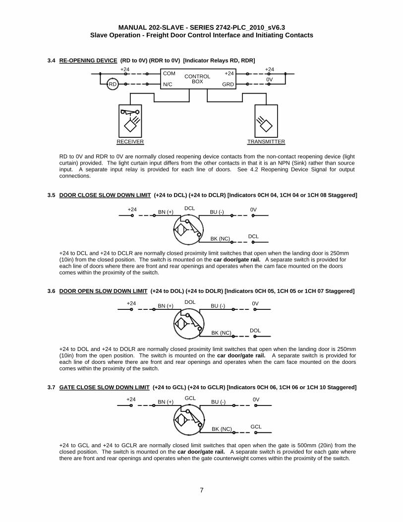
3.4 RE-OPENING DEVICE (RD to 0V) (RDR to 0V) [Indicator Relays RD, RDR]
RD to 0V and RDR to 0V are normally closed reopening device contacts from the non-contact reopening device (light curtain) provided. The light curtain input differs from the other contacts in that it is an NPN (Sink) rather than source input. A separate input relay is provided for each line of doors. See 4.2 Reopening Device Signal for output connections.
3.5 DOOR CLOSE SLOW DOWN LIMIT (+24 to DCL) (+24 to DCLR) [Indicators 0CH 04, 1CH 04 or 1CH 08 Staggered]
+24 to DCL and +24 to DCLR are normally closed proximity limit switches that open when the landing door is 250mm (10in) from the closed position. The switch is mounted on the car door/gate rail. A separate switch is provided for each line of doors where there are front and rear openings and operates when the cam face mounted on the doors comes within the proximity of the switch.
3.6 DOOR OPEN SLOW DOWN LIMIT (+24 to DOL) (+24 to DOLR) [Indicators 0CH 05, 1CH 05 or 1CH 07 Staggered] +24 to DOL and +24 to DOLR are normally closed proximity limit switches that open when the landing door is 250mm (10in) from the open position. The switch is mounted on the car door/gate rail. A separate switch is provided for each line of doors where there are front and rear openings and operates when the cam face mounted on the doors comes within the proximity of the switch.
3.7 GATE CLOSE SLOW DOWN LIMIT (+24 to GCL) (+24 to GCLR) [Indicators 0CH 06, 1CH 06 or 1CH 10 Staggered]
+24 to GCL and +24 to GCLR are normally closed limit switches that open when the gate is 500mm (20in) from the closed position. The switch is mounted on the car door/gate rail. A separate switch is provided for each gate where there are front and rear openings and operates when the gate counterweight comes within the proximity of the switch.
BU (-)BN (+)
BK (NC) DCL
+24 DCL 0V
+24
GCL
0VBN (+)GCL
BU (-)
BK (NC)
N/C
+24
RD
+24COM
0VCONTROLBOX
RECEIVER TRANSMITTER
+24
GRD

MANUAL 202-SLAVE - SERIES 2742-PLC_2010_sV6.3 Slave Operation - Freight Door Control Interface and Initiating Contacts
8
X15 BY PEELLEGATE OPEN FINAL
X16
+24
BK (NC)
GOLBN (+) BU (-)
GOL
0V
3.8 GATE OPEN SLOW DOWN LIMIT (+24 to GOL) (+24 to GOLR) [Indicators 0CH 07, 1CH 07 or 1CH 11 Staggered]
+24 to GOL and +24 to GOLR are normally closed limit switches that open when the gate is 500mm (20in) from the open position. The switch is mounted on the car door/gate rail. A separate switch is provided for each gate where there are front and rear openings and operates when the cam face mounted on the gate comes within the proximity of the switch.
3.9 DOOR OPEN FINAL (OPTIONAL) (+24 to DOF) (+24 to DOFR) [Indicators 0CH 08, 1CH 08] Where provided on bi-parting doors, +24 to DOF and +24 to DOFR are normally open limit switches mounted on the Peelle hoistway landing door rail that close when the lower door panel is 25mm (1in) from the stop position. A separate switch is provided for each door and wired in parallel to give a hoistway landing door open signal to the door controller. This input is optional and used for the Automatic Stay Open feature on bi-parting doors.
SECTION 4: -OUTPUT SIGNALS AND SAFETY CIRCUIT PROVIDED BY PEELLE- All outputs are dry (voltage free) contacts to the elevator controller. 4.1 CAR DOOR/GATE OPEN FINAL SIGNAL (X15 to X16) (X15R to X16R)
X15 to X16/X17R and X15R to X16R/X17R are isolated contacts from relay GOF and GOFR from the Gate Open Limit. Both normally open and normally closed contacts are provided. For normally open signal that closes when the gate is open, connect wires from X15 to X16. A separate signal is provided for each gate to give an open door signal to the elevator controller.
4.2 REOPENING DEVICE SIGNAL (X22 to X23/X24) (X22R to X23R/X24R) [Relay RD, RDR] X22 to X23/X24 and X22R to X23R/X24R are isolated contacts from relays RD and RDR from the Reopening Device (Light Curtain). Both normally open and normally close contacts are provided. For a normally open signal that closes when the beam is broken, connect wires from x22 to X23. The output of the reopening device receiver should be wired into RD or RDR to energize the relay when the beam is not broken. A separate signal is provided for front and rear reopening device signals to the elevator controller.

MANUAL 202-SLAVE - SERIES 2742-PLC_2010_sV6.3 Slave Operation - Freight Door Control Interface and Initiating Contacts
9
4.3 DOOR AND GATE CLOSED SIGNAL (X19 to X20) (X19R to X20R) [Indicators 10CH 00, 10CH 01]
X19 to X20 and X19R to X20R are contacts from the Peelle controller that close when door and car gate close operation is complete. A separate signal is provided for front and rear door close signals to the elevator controller. NOTE: This signal is subject to reset in the event or power failure and should be used for control purposes only. If a physical connection to the car gate independent of the door controller is required, use the Landing Door and Car Door Closed Signal provided in the Interlocking Circuit.
4.4 DOOR AND CAR GATE INTERLOCKING CIRCUITS (X1 to X9)
DC
X1
X2
(TOP)X3YDC DC
GC
(BOT.)
LINE "C" REAR(IF REQUIRED)
DIDI X9A X9
(BOT.)DCDC X8A X8
GC X7
LANDING DOORLOCKED SIGNAL
CLOSED SIGNALLANDING DOOR
CLOSED SIGNALCAR GATE
(TOP)
(TOP)X5AX5
X6
DI(BOT.) (TOP)
X5YDI DI
X3A
HOISTWAY DOORACCESS BYPASS
CAR GATE ACC. BYPASS
(BOT.)X3
X4
X3Y
X3A LOWEST FLR.
TOP FLR.
Approved interlocks are required when power operated vertically sliding elevator doors are installed. The Peelle supplied interlock arrangement requires that: 1. All DC (hoistway door closed) and GC (car gate closed) contacts be connected in series and that the contacts be
made when the doors and gates are closed. 2. All DI (hoistway door locking) contacts be connected in series and that the contact be made when the doors are
locked.
When the elevator controller is signaled, “all doors closed”, the elevator controller may initiate retiring cam operation (see Retiring Cam Initiation Contact). Initiation will cause the retiring cam face to retire (lift). When the interlock device is no longer depressed by pressure of the retiring cam face, hoistway door locking action takes place and the elevator controller is signaled that the hoistway doors locking action is complete. The elevator controller shall not allow the elevator car to run unless all DC (hoistway door closed) and GC (gate closed) and DI (hoistway door locking) contacts are made.
MANUAL 202-SLAVE - SERIES 2742-PLC_2010_sV6.3 Slave Operation - Freight Door Control Interface and Initiating Contacts
10
UNLOCKINGDEVICES ZNS
(HOISTWAY EQUIPMENT)
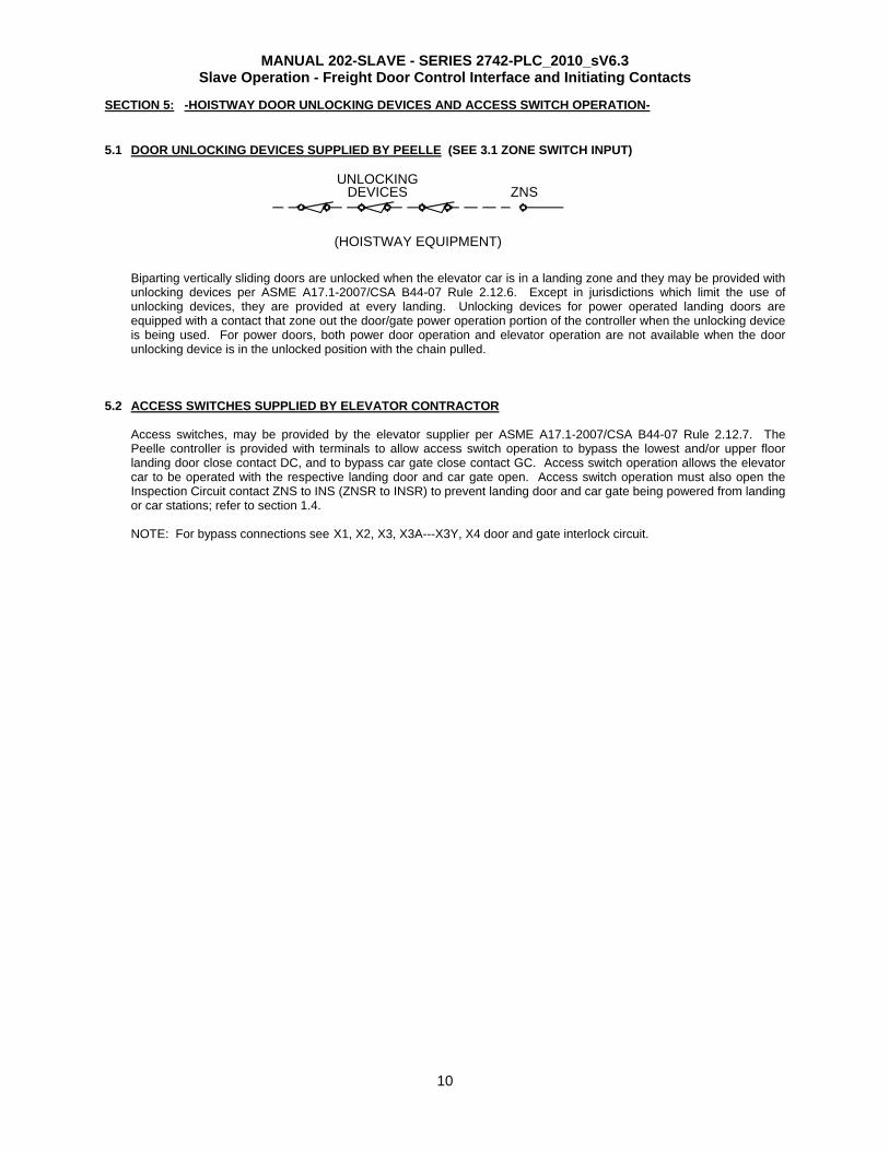
SECTION 5: -HOISTWAY DOOR UNLOCKING DEVICES AND ACCESS SWITCH OPERATION-
5.1 DOOR UNLOCKING DEVICES SUPPLIED BY PEELLE (SEE 3.1 ZONE SWITCH INPUT)
Biparting vertically sliding doors are unlocked when the elevator car is in a landing zone and they may be provided with unlocking devices per ASME A17.1-2007/CSA B44-07 Rule 2.12.6. Except in jurisdictions which limit the use of unlocking devices, they are provided at every landing. Unlocking devices for power operated landing doors are equipped with a contact that zone out the door/gate power operation portion of the controller when the unlocking device is being used. For power doors, both power door operation and elevator operation are not available when the door unlocking device is in the unlocked position with the chain pulled.
5.2 ACCESS SWITCHES SUPPLIED BY ELEVATOR CONTRACTOR Access switches, may be provided by the elevator supplier per ASME A17.1-2007/CSA B44-07 Rule 2.12.7. The Peelle controller is provided with terminals to allow access switch operation to bypass the lowest and/or upper floor landing door close contact DC, and to bypass car gate close contact GC. Access switch operation allows the elevator car to be operated with the respective landing door and car gate open. Access switch operation must also open the Inspection Circuit contact ZNS to INS (ZNSR to INSR) to prevent landing door and car gate being powered from landing or car stations; refer to section 1.4. NOTE: For bypass connections see X1, X2, X3, X3A---X3Y, X4 door and gate interlock circuit.
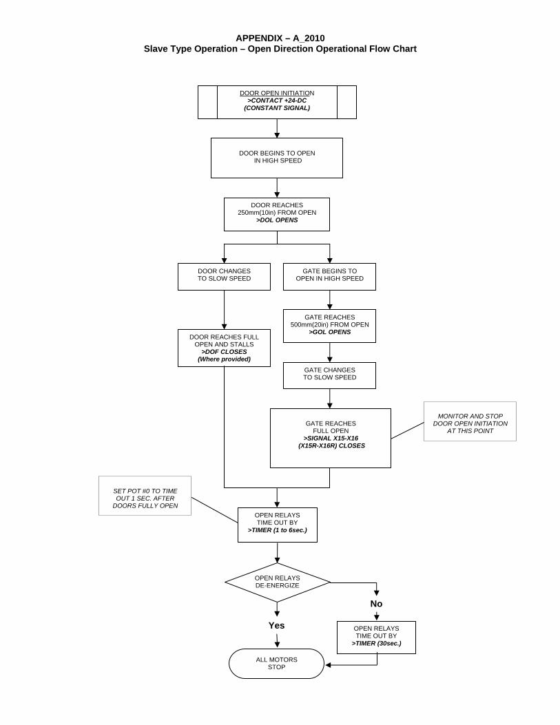
APPENDIX – A_2010 Slave Type Operation – Open Direction Operational Flow Chart
DOOR BEGINS TO OPEN
IN HIGH SPEED
DOOR REACHES 250mm(10in) FROM OPEN
>DOL OPENS
DOOR CHANGES TO SLOW SPEED
GATE BEGINS TO OPEN IN HIGH SPEED
DOOR REACHES FULL OPEN AND STALLS
>DOF CLOSES (Where provided)
GATE REACHES 500mm(20in) FROM OPEN
>GOL OPENS
GATE CHANGES TO SLOW SPEED
GATE REACHES
FULL OPEN >SIGNAL X15-X16
(X15R-X16R) CLOSES
OPEN RELAYS DE-ENERGIZE
No
ALL MOTORS STOP
Yes OPEN RELAYS TIME OUT BY
>TIMER (30sec.)
DOOR OPEN INITIATION >CONTACT +24-DC
(CONSTANT SIGNAL)
MONITOR AND STOP
DOOR OPEN INITIATION AT THIS POINT
OPEN RELAYS TIME OUT BY
>TIMER (1 to 6sec.)
SET POT #0 TO TIME OUT 1 SEC. AFTER
DOORS FULLY OPEN
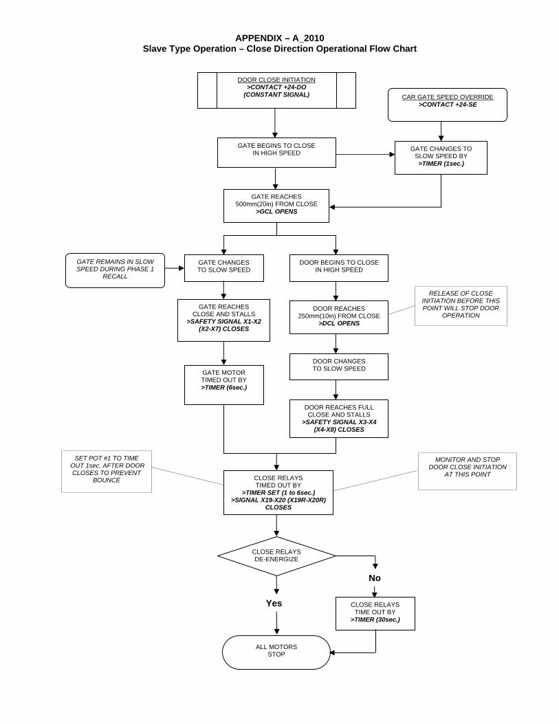
APPENDIX – A_2010 Slave Type Operation – Close Direction Operational Flow Chart
GATE BEGINS TO CLOSE IN HIGH SPEED
GATE REACHES 500mm(20in) FROM CLOSE
>GCL OPENS
GATE CHANGES TO SLOW SPEED
DOOR BEGINS TO CLOSE IN HIGH SPEED
GATE REACHES CLOSE AND STALLS
>SAFETY SIGNAL X1-X2 (X2-X7) CLOSES
DOOR REACHES 250mm(10in) FROM CLOSE
>DCL OPENS
DOOR CHANGES TO SLOW SPEED
DOOR REACHES FULL CLOSE AND STALLS
>SAFETY SIGNAL X3-X4 (X4-X8) CLOSES
CLOSE RELAYS DE-ENERGIZE
No
ALL MOTORS STOP
Yes CLOSE RELAYS TIME OUT BY
>TIMER (30sec.)
DOOR CLOSE INITIATION >CONTACT +24-DO
(CONSTANT SIGNAL)
GATE MOTOR TIMED OUT BY >TIMER (6sec.)
CLOSE RELAYS TIMED OUT BY
>TIMER SET (1 to 6sec.) >SIGNAL X19-X20 (X19R-X20R)
CLOSES
RELEASE OF CLOSE INITIATION BEFORE THIS POINT WILL STOP DOOR
OPERATION
SET POT #1 TO TIME OUT 1sec. AFTER DOOR
CLOSES TO PREVENT BOUNCE
CAR GATE SPEED OVERRIDE >CONTACT +24-SE
GATE CHANGES TO SLOW SPEED BY >TIMER (1sec.)
GATE REMAINS IN SLOW SPEED DURING PHASE 1
RECALL
MONITOR AND STOP DOOR CLOSE INITIATION
AT THIS POINT
ON
STA
TEO
N F
OR
MO
ME
NTA
RY
/ A
UTO
MA
TIC
CLO
SE
A
ON
FO
R S
LOW
SP
EE
D C
AR
DO
OR
OP
ER
ATI
ON
SO
N F
OR
SIM
ULT
AN
EO
US
OP
ER
ATI
ON
F
Sig
nal
Nam
eFr
ont
Indi
cato
rR
ear
Indi
cato
r
Lift
Trav
elin
g B
etw
een
Floo
rs
Lift
Arr
ives
at
Flo
orD
oors
Fin
al
Ope
ning
Doo
rs F
ully
O
pen
Doo
rs F
inal
C
losi
ngD
oors
Ful
ly
Clo
sed
RC
0CH
00
ZNS
0CH
01
1CH
01
SE
0CH
02
1CH
02
SD
O0C
H 0
31C
H 0
3D
CL
0CH
04
1CH
04
DO
L0C
H 0
51C
H 0
5G
CL
0CH
06
1CH
06
GO
L0C
H 0
71C
H 0
7D
OF
0CH
08
1CH
08
DC
0CH
09
1CH
09
DC
M0C
H 1
01C
H 1
0F
FS
LA0C
H 1
1B
UZ
10C
H 0
2R
CR
10C
H 0
3O
10C
H 0
411
CH
02
C10
CH
05
11C
H 0
3D
H10
CH
06
11C
H 0
4D
L10
CH
07
11C
H 0
5G
H11
CH
00
11C
H 0
6G
L11
CH
01
11C
H 0
7X
15-X
16X
19-X
2010
CH
00
10C
H 0
1G
C(X
1-X
2)(X
2-X
7)D
C(X
3-X
4)(X
4-X
8)D
I(X
5-X
6)(X
6-X
9)
F
Land
ing
Doo
r C
losi
ng
S F
S FF
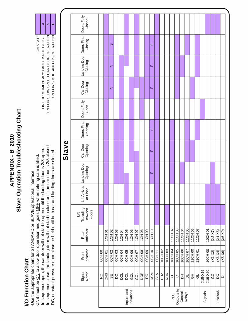
Sla
ve
APP
END
IX -
B_2
010
Slav
e O
pera
tion
Trou
bles
hoot
ing
Cha
rt
Land
ing
Doo
r O
peni
ngC
ar D
oor
Ope
ning
Car
Doo
r C
losi
ng
I/O F
unct
ion
Cha
rt-U
se th
e ap
prop
riate
cha
rt fo
r STA
ND
AR
D o
r SLA
VE
ope
ratio
nal i
nter
face
-ZN
S m
ust b
e O
N to
allo
w d
oor o
pera
tion
and
goes
OFF
whe
n re
tirin
g ca
m is
lifte
d.-In
seq
uenc
e op
en, t
he c
ar d
oor w
ill n
ot s
tart
to o
pen
until
the
land
ing
door
is 2
/3 o
pen.
-In s
eque
nce
clos
e, th
e la
ndin
g do
or w
ill n
ot s
tart
to c
lose
unt
il th
e ca
r doo
r is
2/3
clos
ed-D
C, c
onst
ant p
ress
ure
door
clo
se b
e he
ld u
ntil
both
car
and
land
ing
door
s ar
e cl
osed
.
Inpu
ts a
nd
Initi
atio
ns
Inte
rlock
Sig
nals
PLC
O
utpu
ts to
C
ontro
l R
elay
s

MANUAL 201 – SERIES 2742-PLC_2010_sV6.3 Freight Door Control Sequence of Operations
1
www.peelledoor.com
FREIGHT ELEVATOR DOOR DETAILED OPERATIONS MANUAL
FOR LOGIC CONTROLLER SERIES 2742-PLC (274200 to 274202)
TABLE OF CONTENTS
1. GENERAL DESCRIPTIONS OF POWER DOORS 1.1 COMPONENT ASSEMBLIES 1.2 COMPONENT ASSEMBLIES DESCRIPTIONS
2. BASIC POWER AND CONTROL OPERATIONS 2.1 POWER CIRCUIT 2.2 CONTROL CIRCUIT
3. SEQUENCE OF OPERATION 3.1 SEQUENCE OPERATION
3.1.1 OPENING DIRECTION 3.1.2 CLOSING DIRECTION 3.1.3 AUTOMATIC REOPENING 3.1.4 REOPENING DEVICE 3.1.5 STOPPING OF DOORS/GATES 3.1.6 CAR LEAVING LANDING 3.1.7 REAR LINE OF A DOUBLE LINE OF DOORS 3.1.8 DOUBLE LINE OF DOORS AT STAGGERED LEVELS
3.2 ALTERNATE -MODIFIED LIMIT ARRANGEMENT 3.3 FIREFIGHTERS SERVICE
3.3.1 GENERAL 3.3.2 PHASE I 3.3.3 PHASE II
4. MOMENTARY PRESSURE PUSHBUTTON AND AUTOMATIC TIME CLOSING OPERATION - OPTIONAL 4.1 CODE REQUIREMENTS 4.2 OTHER FEATURES 4.3 MOMENTARY PRESSURE CLOSING OPERATION 4.4 AUTOMATIC TIME CLOSING 4.5 HOLD OPEN OPERATION 4.6 FIREMANS SERVICE AND AUTOMATIC CLOSING
APPENDIX – A CONTROLLER PART NUMBERS APPENDIX – B PEELLE MOTOR DATA
We still service equipment we built 50 years ago
Freight Elevator Doors Since 1905 ®

MANUAL 201 – SERIES 2742-PLC_2010_sV6.3 Freight Door Control Sequence of Operations
2
1. GENERAL DESCRIPTION OF POWER DOORS. Power Doors are generally operated by two Peelle power door operators, one on each side of each hoistway-landing door. Power door operation is recommended for doors larger than 2400mm wide by 2400mm high/ 8 feet wide by 8 feet high. Note: Where the term Gate or Car Gate is used, it is inclusive of Car Doors. Where the term Door is used, it means Hoistway Landing Door. Under normal operation the Peelle drive system for freight elevator power doors maintains full control of the doors and gates through their complete cycle of operation. Under slave operation, control interface is required to maintain the door operation. Door/gate travel is regulated by individual limit switches. Motor speed is controlled to ensure full travel without slamming. The equipment permits immediate manual operation in the event of power failure. Each car gate operates in conjunction with an associated hoistway-landing door. Power operated doors and gates can be initiated to open automatically as the elevator arrives at a floor and to close by either continuous-pressure or momentary-pressure pushbutton operation. Under continuous-pressure operation door and gate will reopen automatically if not closed to full limit switch operation before the close pushbutton is released. The equipment is designed for three phase A.C. power supplies of 50/60 Hz. See job specific schematic diagrams for voltage details. 1.1 POWER DOORS/GATES -COMPONENT ASSEMBLIES
1. Hoistway Landing Doors and Car Gate(s). 2. Power Door Operator –generally two for each door. 3. Power Gate Operator –one for each car gate. 4. Door Speed Limit Switches –two for each car gate
and two per line of doors. 5. Door Open Limit Switch –one for each hoistway
landing door and one for each car gate. 6. Interlock (Door Locking Device) –one for each
hoistway landing door (includes Door Closed Contact DC and Door Locking Contact DI plus Motor and Control Zone Switches Z).
7. Gate Contact –one for each car gate. 8. Controller –one controller for each elevator. A Front
Line (Line A) of doors includes all the hoistway doors providing entrance to the front end of the elevator and a Rear Line (Line C) includes all the hoistway doors providing entrance to the rear end of the elevator car. (Also see Staggered Openings Section 3.1.8) and Car Gate Motor Section 2.1.3).
9. Pushbutton Station –one station for each car gate when car operation is from inside only, and another station at the landing for each door if elevator is fully automatic. Note: Pushbutton Stations are usually supplied by the elevator company.
10. Retiring Cam -generally one for each line of doors to operate interlocks (a retiring cam unlocks doors, activates Door Locking Contact DI and Zone Contacts Z).
11. Door Unlocking Devices -Unlocking devices are used for emergency egress to the hoistway and are required at every landing. Where access switches (by elevator installer) have not been provided,
unlocking devices may be used to access the pit and/or the car top for inspection, maintenance and repair when provided at the lowest landing and an upper landing.
12. Reopening Device -usually one for each line of doors mounted on the car gate rails.
1.2 COMPONENT ASSEMBLIES DESCRIPTIONS
1. Hoistway Landing Doors and Car Gate(s). The hoistway landing doors, (vertically sliding biparting or two-section slideup) are suspended by roller chains from two power door operators mounted one on each door rail just above the head of the frame. The slideup car gate is counterbalanced by a guided counterweight. The gate counterweight travels in a track mounted on the outside of the car enclosure. A power gate operator with a double chain drive provides the opening and closing effort for the car gate. Each car gate is usually equipped with a reopening device. Initiation of the device during gate close travel will cause the gate to return to full open position. Under several conditions where the reopening device is rendered inoperative (see section 3.1.4), car gate close travel will be at slow speed only.
2. Power Door Operator and Power Gate Operator. The power operator assemblies consist of two-speed, torque motors that drive the sheaves by means of pinion and gear. The high speed is for the main travel. The slow speed serves as a dynamic slow-down when in the slow speed zone to ensure full panel travel without slamming.
3. Limit Switches. The limit switches control the travel length of the high speed zone and the start of the slow speed zone. The end of the slow speed zone cutoff is determined by a final limit timer. The arrangements of control circuits in the controller, and the setting of the limit switches, will start the door and / or gate, either to open or close, at the high speed power, will switch to slow speed power to dampen the inertia by initiating a dynamic braking effort and slow the door or gate down.
4. Interlock and Gate Contact. The interlock [hoistway door locking device], one located at each opening, is a combination assembly serving as a mechanical door lock, an electric interlock, and a zone selector. The lower portion of the door interlock has a contact DC operated by action of the door panel. The upper portion has a contact DI and a series of zone contacts Z operated by action of a retiring cam mounted on the car. The gate contact GC on the car gate rail is operated by action of the car gate counterweight. Elevator operation is prevented unless the car gate contact GC, door contacts DC, and the retiring cam operated DI contacts, are all closed.
5. Controller. The door controller is usually located in the elevator machine room and can be mounted on the wall or set on a floor-supported frame. The door controller contains the power contactors and logic functions to direct the door operation in accordance with the requirements. Under Slave Type Operation some of the logic functions are required in the elevator controller. The power circuit for all controller types is based on 208/220/240 Volt A.C., three phase, 50/60 Hertz. Other three phase AC voltages will have
MANUAL 201 – SERIES 2742-PLC_2010_sV6.3 Freight Door Control Sequence of Operations
3
transformers to provide the basic power. Transformers are included in the controller. The controller has, besides the terminal blocks and fuses, the following components: a. PLC - Programmable Logic Controller b. PSU - Power Supply Unit c. O & C - Open and Close Main Direction
Relays, mechanically/electrically interlocked. d. DH & DL, GH & GL - Door & Gate High and
Slow Speed Relays, with High & Slow Speeds mechanically/electrically interlocked.
e. RCR - Retiring Cam Relay. f. TRSF -Power Transformer. g. RD - Reopening Device Relay h. ZNS - Zone Switch Relay i. Firefighters Service Relay Group:
(1) ES: Phase II Relay (2) ESO: Phase II Off Relay
6. Pushbutton Station. Door operation requires momentary action door-operating pushbuttons.
7. Retiring Cam. The retiring cam (motor driven) is lifted (retired) by a torque motor that is powered and stalls during elevator travel. Lifting and gravity dropping of the retiring cam operates the interlocks. At least one retiring cam is usually furnished for each line of doors and is mounted on the elevator car. A second retiring cam is supplied if side opposite locks are furnished.
8. Reopening Device. The reopening device detects an obstruction to the normal closing of the car gate and causes the car gate and associated hoistway landing door, if closing, to reopen. There are two reopening device types: a) non-contact (infrared beam) (see section 3.1.4) and b) contact (reversing-edge).
2. BASIC POWER AND CONTROL OPERATIONS
(Refer to Job Schematic) 2.1 POWER CIRCUIT 2.1.1 GENERAL
The power circuit for the motors is based on 208-220 VAC, 3 phase, 50/60 Hertz power. Higher incoming voltages will have a transformer built into the controller. Hoistway door operators are shipped in right and left hand pairs. Their high and slow speed motor windings are directionally phased at the factory. The entire line of door operator motors and the gate operator motor can be phased for open or close direction at the controller. Note: when an individual motor is replaced or relocated, it must be phase checked at the motor for proper direction rotation. The retiring cam motor must be phased to provide rotation for proper lift rod direction.
2.1.2 RETIRING CAM MOTOR
If all hoistway landing doors and the car gate are closed, and proper initiation energizes the RCR relay, the retiring cam motor will operate. The retiring cam retires (lifts) allowing the locking arm to extend, locking the door, opening all Z contacts, and closing the door interlock contact DI. If there are two lines of doors, a separate retiring cam will be furnished for the Rear Line. When so furnished, it is connected in parallel with the retiring cam motor of the Front Line, and operates at the same time. In some cases there are two retiring cams
per line of doors and they are also connected in parallel.
2.1.3 CAR GATE MOTOR 1. If contacts O and GH “make up”, the car gate
motor will operate at high speed in the open direction. If contacts C and GH “make up”, the car gate motor will operate at high speed in the close direction.
2. If contacts O and GL “make up”, the car gate motor will operate at slow speed in the open direction. If contacts C and GL “make up”, the car gate motor will operate at slow speed in the close direction.
3. A rear line of doors is considered “staggered” when no rear landing elevation is within 350mm / 14 in. above or below the elevation of a front landing. If there is a “staggered” rear line of doors, a single line controller is used to operate all the doors/gates including the rear line gate by the use of a SG gate selector. With normally open SG contacts remaining open as shown on the controller schematic diagram, the front line gate motor will operate. With normally open SG contacts “made up” the rear line gate motor will operate.
2.1.4 DOOR MOTORS
Zone control by landing: 1. If the elevator car is within 300mm / 12 in.
above or below the floor and the door zone switch has been operated by the retiring cam, closing all Z contacts at that door, then:
2. If contacts O and DH “make up”, the hoistway landing door motors will operate at high speed in the open direction. If contacts C and DH “make up”, the hoistway door landing motors will operate at high speed in the close direction.
3. If contacts O and DL “make up”, the hoistway landing door motors will operate at slow speed in the open direction. If contacts C and DL “make up”, the hoistway landing door motors will operate at slow speed in the close direction.
2.1.5 POWER OPERATION OF DOORS AND GATES
The arrangement of the control circuits below and the setting of the Limit Switches are to provide initial power to the high-speed motors. This will start the door and/or gate, either opening or closing at high speed, and then at the final travel position will apply the slow speed power to dampen the inertia and slow the door or gate down. Refer to installation Manual 203 covering the setting of Door and Gate Limit Switches.
2.2 CONTROL CIRCUIT 2.2.1 GENERAL
Standard Door Operation is based on using pushbuttons and applying momentary-pressure for the open direction and continuous-pressure for the closed direction. A power transformer is provided with each controller to supply 208-220 VAC three phase for the motor power circuit, the PLC and the PSU. The
MANUAL 201 – SERIES 2742-PLC_2010_sV6.3 Freight Door Control Sequence of Operations
4
PSU provides 24 VDC for all input and output relay circuits. The negative side of the 24 VDC output is grounded Relays O and C are Direction Relays, O for open direction and C for close direction. These relays are mechanically and electrically interlocked set up the direction of the door and gate motors at the start of an operation, and remain energized until the final door and gate travel. High speed relays, DH for the door and GH for the gate, become energized sequentially when either O or C relays become energized to power the high speed winding of door and gate motors. They remain energized until the door is approximately 250mm / 10in. from the end of its travel and the car gate is 500mm / 20in. from the end of its travel, when the door and the gate slow speed limits are actuated. When the slow speed limits actuate the slow speed relays, DL for the door and GL for the gate, are energized, the slow speed windings allow the motors to dynamically brake and check the speed of the door and gate to prevent slamming at the end of travel where the final limit timers are actuated and relays O or C and DL and GL become de-energized. The control will initiate the open direction if close direction is interrupted (by the release of the door close pushbutton or operation of the reopening device). Interruption of the non-contact reopening device or initiation of the door open button (or pressure on the contact-type reversing edge) will interrupt the closing direction and the control will instantly initiate the open direction causing full open travel. The non-contact reopening device will be deactivated and gate/door speed will be restricted to slow speed (low KE) during firefighter emergency operation Phase 1 Recall where it is required that devices affected by smoke must be disabled.
The control has built in directional time protection. This time protection provides 30 seconds for normal door and gate open/close functions. If normally door function is completed within this time allowance the protection resets prior to the next operation.
Mis-operation of door or car gate travel or limit switches, that sends a continuous direction signal beyond the normal time span will force operation of the respective time protection which will de-energize the associated power control relays. The time protection will remain on until a door operating pushbutton initiation after clearing the fault.
Holding door-open-button in the car will open the doors and will override any door close input to the controller from the door close button either in the
car or at the landing or from automatic closing initiation from the controller.
2.2.2 RETIRING CAM OPERATION
The RC input controls the operation of the retiring cam. When elevator operation is initiated, a contact on the elevator controller is made, causing the RCR relay to energize, operating the cam motor and lifting the cam into a retired position. When the car levels to a floor or is standing at the floor, the contact on the elevator controller opens, de-energizing the RCR relay. This permits the cam to extend by gravity, engaging the interlock/zone switch roller. The cam remains extended until the door and gate are completely closed and the car is signaled to move to another landing. The elevator controller should initiate the retiring cam through RC only when the elevator is called to a floor and while traveling. De-energize the RC whenever the car is stopped! For auto-open at a landing first de-energize the retiring cam within the landing zone. This will allow the zone switch to be made up completely before power is applied to the door motors. This sequence prevents power from being applied to the door motor before the door is completely unlocked. The doors are unlocked at the same time as the zone switch is made up. The elevator circuitry must also provide that the initiation of RC be subject to both the hoistway landing door (DC) and car gate (GC) contacts and neither contact individually. Further, if the cam retires (lifts), but the hoistway landing door interlock (DI) contact does not “make up”, or the car does not run for some other reason, the initiation to RC should be discontinued after a short time period. The controller has a built in duty cycle protection for the retiring cam. Peelle torque motors are limited in duty and therefore need sufficient amount of rest or cool down time, when compared to their on-time. The motor’s on-time is continually compared to the amount of off-time. Should the motor exceed its associated duty cycle the duty cycle protection will de-energize the RCR relay. The duty cycle protection will remain on until the motor is re-initiated by the retiring cam initiation. Re-initiation does not reset the duty cycle protection. If the motor is initiated again before sufficient cool down time is achieved, the motor will have limited on-time available up to the associated duty cycle. Duty cycle protection can only be completely reset after appropriate off-time (cool down).
2.2.3 FIREFIGHTERS SERVICE 1. Firefighters service is included in the logic system of
the Peelle controller number 274200 to 274202. 2. Where Firefighters Service is not required,
Firefighters Service initiating contacts should be left unconnected.
3. A write-up of Firefighters Service is provided in Section 3.4.
2.2.4 ELEVATOR-TO-DOOR INITIATIONS AND THEIR PANEL TO PANEL CONNECTIONS
MANUAL 201 – SERIES 2742-PLC_2010_sV6.3 Freight Door Control Sequence of Operations
5
1. Each schematic diagram has a list of the elevator controller-to-door controller panel connections necessary for operation of the logic system. The terminal wiring number on the elevator controller is listed when there is a timely return of the Peelle drawing submission sheets.
2. A complete explanation of initiations and their panel to panel connections are covered in Peelle Manual #202 –Freight Door Control Interface and Initiating Contacts. Select the right manual for Standard Operation and Slave Type Operation.
3. SEQUENCE OF OPERATION - EXPLANATION
3.1 SEQUENCE OPERATION – Hoistway Door and Car Gate Based on: Peelle Schematic #274200, single line of doors. Peelle Schematic #274201 for double line of doors. Peelle Schematic #274202 for double line of doors at staggered levels. Sequence operation, standard, is a door and gate operating system where the hoistway landing door is at least 2/3 open prior to the opening of the adjacent car gate, and the car gate is at least 2/3 closed prior to the closing of the adjacent hoistway landing door. Sequence Operation meets the requirements of ASME A17.1-2007/CSA B44-07 Rule 2.13.6 and EN81-1 Rule 7.5.2.2.
3.1.1.OPENING DIRECTION-SEQUENCE OPERATION; LIMIT SWITCH SLOWDOWN AND TIMED FINAL LIMITS.
1. All doors and car gates being closed, the elevator car at the landing, and with the retiring cam extended pushing the locking arm roller causing zone contacts Z to be closed:
2. When the car is level, automatic opening is initiated by the elevator control through contact +24 to DO which parallels the door open pushbutton circuit.
3. When contacts Z are closed and the automatic opening initiating circuit is closed (or door open pushbutton is momentarily pressed, the O open main direction relay energizes and a holding circuit is engaged (momentary input).
4. With door open limit DOL normally closed the controller energizes door high-speed relay DH.
5. The hoistway landing door is now operating in the open direction powered by high-speed motor windings.
6. The hoistway landing door will continue in high speed until it reaches approximately 250mm / 10in. of full opening, at which time the door slow speed limit DOL will open, de-energizing door high speed relay DH and energizing door slow speed relay DL.
7. With DOL open, sequence operation energizes gate high-speed relay GH and the gate starts to open at high speed.
8. The door speed is now changed from high speed to slow speed and the car gate is now operating at high speed.
9. The door continues at slow speed to full open position and where provided actuates door final limit switch DOF (optional). The door remains held at this full open position with the motor stalled.
10. Similarly the gate continues in high speed until it reaches approximately 500mm / 20in. from its full open position, the gate low speed limit GOL opens, de-energizing gate high speed relay GH and energizes gate slow speed relay GL.
11. The gate speed is now being changed from high speed to slow speed and continues at slow speed until full open position and remains held under stalled slow-speed power until the final open timer actuates. At this position the gate open final contact GOF actuates.
12. The car gate will travel at slow-speed to full open. Note: the open final timer must be set by Potentiometer #0 with sufficient time for the slow-speed travel to complete plus a 1 second stall before timing out. Upon completion of the time as set by POT #0 (1 to 6 seconds), main open relay O and door and car gate slow-speed relays DL and GL de-energize.
13. Should the door rebound or not open completely, pushing the door open pushbutton again will provide slow speed power on the door and gate for a new time allowance of open final timer (as set by POT#0, 1 to 6 seconds).
14. Where provided DOF door open final limit switch acts as an Auto-Stay-Open (ASO) limit.
15. OPTIONAL: With Auto-Stay-Open (ASO), should the door rebound causing DOF final limit to open, slow-speed power is then applied to the door and gate motors until the open final timer times out. This will power the door and/or gate back to the full open position.
16. Should the open direction be energized for 30 seconds continuously, without completing an operation, the time protection will reset and de-energize the open direction and speed relays. They will remain de-energized until the fault is corrected and the door open or close pushbutton is operated.
3.1.2 CLOSING DIRECTION-SEQUENCE OPERATION; LIMIT SWITCH SLOWDOWN AND TIME FINAL LIMITS
1. With the door and car gate in the open position, and with zone contacts Z closed, no open initiation and open direction relays de-energized, continuous-pressure of the car or landing door close pushbutton will close circuit +24 to DC and initiate closing. The close direction relay C energizes.
2. With gate closed limit GCL normally closed the controller energizes gate high-speed relay GH.
3. The car gate is now operating in the closed direction powered by high-speed motor windings.
4. The car gate will continue in high speed until approximately 500mm / 20in. before full closed position, at which time the slow speed gate limit GCL will open, de-energizing gate high speed relay GH and energizing gate slow speed relay GL.
5. With GCL open, sequence operation energizes door high-speed relay DH and the door starts to close at high speed.
MANUAL 201 – SERIES 2742-PLC_2010_sV6.3 Freight Door Control Sequence of Operations
6
6. The gate is now changed from high speed to slow speed and the door is now operating at high speed.
7. The gate continues at slow speed to full closed position. The gate remains held at this full closed position stalled until the gate motor cutoff timer activates (6 seconds).
8. Similarly, the door continues in high speed until it reaches 250mm / 10in. from the full closing position, at which time slow speed door limit DCL will open, de-energizing the door high speed relay DH and energizing the door slow speed relay DL.
9. The door is now being changed from high speed to slow speed. The door will continue to travel at slow speed to full close position. The door remains held under stalled slow speed power until the final close timer actuates. Note: the close final timer must be set by Potentiometer #1 with sufficient time for the slow speed travel to complete plus a 1 second stall before timing out. Upon completion of the time as set by POT #1 (1 to 6 seconds), close direction relay C and door slow speed relay DL de-energize.
10. Should the door rebound or not close completely, pushing the door close pushbutton again will provide slow speed power on the door and gate for a new time allowance of final close timer (as set by POT#1, 1 to 6 seconds).
11. Should the close direction be energized for 30 seconds continuously, without completing an operation, the time protection will reset and de-energize all close direction and speed relays. They will remain de-energized until the fault is corrected and the door open or close pushbutton is operated.
3.1.3 AUTOMATIC REOPENING
1. Reopening takes place anytime during door and gate travel if the close pushbutton is released.
2. The open direction will initiate and continue as outlined beginning with item 3. of 3.1.1 Opening Direction.
3.1.4 REOPENING DEVICES (NON-CONTACT
DEVICES) 1. Reopening devices consisting of a light curtain
extend across the full width of the gate. The device is wired to the normally closed input +24 to RD. (NOTE: A contact-type reversing edge reopening device may be optionally included as a backup to the non-contact re-opening device. It is mounted directly on and across the full width of the gate leading edge. See item 7. below for electrical connection.)
2. The reopening devices are active for the entire travel of the gate and door.
3. With the gate returned to its fully open position and the door fully open (if the door is not fully open it will also return to its fully open position), the door and gate will respond normally to a new close initiation.
4. When Phase I is initiated through an elevator control signal the reopening device circuitry will provide a slow speed low KE gate close
operation and light curtain inputs will be ignored. This will initiate gate closing in slow speed. Slow speed mode is held in until full close.
7. Addition of a physical contact type reversing edge can be incorporated. It is to be connected to initiation contact +24 to RE. Physical action on the reversing edge will cause the opening circuit to function in the same manner as with the open initiation. If the edge should short out, the doors will re-open and remain open indefinitely.
3.1.5 STOPPING OF DOORS / GATES
1. A door stop pushbutton in the car station is standard, while non-inclusion is optional.
2. To stop the doors and gate while closing, release the door close pushbutton. This will brake the closing inertia and reopen the doors/gates.
3. Momentary pressure on the door stop button in the car station control will de-energize power to the door and gate motors.
4. To stop the door and gate while opening, momentarily press the stop pushbutton in the car station to de-energize the control, thus removing power from the door and gate motors; some coasting will be experienced.
5. To stop the door and gate while closing under automatic means, momentarily press the stop pushbutton in the car station or press the open button. The stop button will de-energize the control and remove power from the door and gate motors while the open button will reopen the doors/gates.
6. After a door stop pushbutton operation, it will be necessary to reinitiate the desired operation (open or close).
7. In the event de-energization of the control is desired, continuous pressure on the door stop pushbutton will de-energize all door-open and door-close control circuits.
3.1.6 CAR LEAVING LANDING
1. When a hoistway landing door is closed, the door contact DC actuated by the door panel is closed.
2. When gate is closed, the gate contact GC actuated by the cam on gate counterweight is closed.
3. With door contacts DC and gate contact GC closed; when a floor selector button is pressed on the car-operating-panel, the contact RC on the elevator controller that initiates the retiring cam closes.
4. Contact RC on the elevator controller closes and initiates +24 to RC. With all door power relays de-energized, Peelle RCR retiring cam relay is energized on the Peelle door controller.
5. The duty cycle protection starts to monitor the retiring cam motor.
6. The retiring cam motor being energized, the cam is retired (lifted), disengaging the locking arm roller. The interlock locking arm is extended which mechanically locks the door,

MANUAL 201 – SERIES 2742-PLC_2010_sV6.3 Freight Door Control Sequence of Operations
7
and causes the door interlock ‘Door Locking’ contact DI in the zone box to close.
7. Contacts GC (gate contact), DC (door contact) and DI (door interlock contact) being closed (all three must be closed), the car moves from the landing with the cam retired.
8. The retiring cam remains retired until the car levels to, or stops at, the selected landing and the elevator controller opens the circuit between +24 to RC.
3.1.7 DOUBLE LINE OF DOORS (Schematic #274201)
1. Where there are openings at the front and rear of the elevator and where at least one rear door is within the level of a front door landing zone, double line schematic is used.
2. All the open and close power relays of the Front Line are duplicated in the Rear Line thereby selective operation of front or rear doors is provided.
3. Isolated contact initiations from the elevator control for Rear Line are required for automatic opening; in addition to the Front Line contact initiations.
4. Front Line and Rear Line retiring cams are powered by the same relay RCR as both cams are to operate in unison.
3.1.8 DOUBLE LINE OF DOORS AT STAGGERED LEVELS
(Schematic #274202) 1. Where there are openings at the front and rear
of the elevator but no rear door landing is within 300mm / 12in. of the level of a front door landing, a single controller, using the staggered line schematic, operates both the Front Line and Rear Line doors and gates.
2. The logic system for staggered opening operation is similar to the Front Line diagram, but modified to operate the rear line gate when the elevator is within the landing zone of a rear line door by the addition of SG input on the controller.
3. One of the Rear Line door zone contacts energizes SG input which then transfers the power feeds from the Front Line gate motor to the Rear Line gate motor.
4. Input SG will select the rear gate and inputs RDR, GOLR, GCLR, DOLR and DCLR. For proper operation the gate opposite to the gate and door being operated should be kept in the closed position.
5. There is a front line retiring cam and a rear line retiring cam. They operate in unison similar to section 3.1.7. When the retiring cams are de-energized and the elevator is at a rear door level, the rear door retiring cam unlocks the rear door and closes the zone contacts. The front line cam extends but with no unlocking action or contact action.
6. Interconnections between the elevator controller and the door controller are similar to a single line, Front Line controller.
3.2 ALTERNATE: MODIFIED LIMIT ARRANGEMENT
3.2.1 Switches for the open/close door and gate slowdown limits DOL, DCL, GOL and GCL are provided to suit the particular NEMA (IP) conditions.
3.2.2 Additionally, under explosion conditions NEMA 7 or 9, some functions are removed from the hazardous hoistway area and handled within the controller. A modified schematic is issued for each particular job covering the job differentials.
3.3 FIREFIGHTERS SERVICE 3.3.1 GENERAL
Provided when required by code on new Automatic Elevators. Automatic freight elevators or Freight Elevators Permitted to Carry Passengers, require special provisions for Firefighters Service. The following are requirements for Peelle doors/ gates to meet the intent of ASME A17.1-2007/CSA B44-07 Rules 2.27.3, 2.27.4 or 2.27.5). These requirements are for vertically sliding doors.
3.3.1.1 Elevators that are defined as “Automatic (non-attendant) Operation Elevators” require conformance to ASME A17.1-2007/CSA B44-07 Rule 2.27.3). Power door controllers set up with Firefighters Service are provided with the logic necessary to alter standard operation of the doors and gate upon receipt of initiations from elevator-company-supplied isolated relay contact for Phase I – Designated / Alternate Landing, and Phase II - In Car Operation for On, Off and Hold. Manual doors, or continuous-pressure pushbutton power operated doors (for closing), require an audiovisual signal provided by elevator supplier/installer, to alert the attendant to close the doors (if open) and return the elevator to the designated level.
3.3.1.2 Elevators that are defined as “Attendant-Operated Elevators, with manually operated or power operated vertical slide doors and car gates, require an audiovisual signal provided by an elevator supplier/installer, to alert the attendant to close the doors (if open) and return the elevator to the designated level. See ASME A17.1-2007/CSA B44-07 Rule 2.27.4.
3.3.1.3 Elevators defined as “Dual Operation Elevators” (attendant/non-attendant per ASME A17.1-2007/CSA B44-07 Rule 2.27.5 when on non-attendant service shall conform to the requirements of ASME A17.1-2007/CSA B44-07 Rule 2.27.3 (see paragraph 1 above). When on attendant service; a) with doors open at a landing, an audiovisual signal provided by the elevator supplier/installer shall alert the attendant to close the doors and alert the passengers that the car is returning nonstop to the designated landing and after 15 to 60 seconds the requirements of ASME A17.1-2007/CSA B44-07 Rule 2.27.3 shall become effective and; b) if the elevator is in flight, shall conform immediately to the requirements of ASME A17.1-2007/CSA B44-07 Rule 2.27.3.
3.3.2 PHASE I – AUTOMATIC OPERATION ELEVATORS 3.3.2.1 When a Phase I isolated initiation is received from
the elevator controller as a result of the recall switch at the designated landing being turned to the ON position or due to smoke detector action:
3.3.2.1.1 With the car standing at a landing other than the designated level and with the doors open:
MANUAL 201 – SERIES 2742-PLC_2010_sV6.3 Freight Door Control Sequence of Operations
8
3.3.2.1.1.1 The door closing sequence (warning bell before door movement) will commence without delay.
3.3.2.1.1.2 If equipped with manually operated doors or power doors with Continuous-Pressure closing, the audiovisual signal installed by the elevator supplier/installer shall alert an attendant to manually or power operate the doors to a closed position.
3.3.2.1.2 With the elevator on Inspection Service at the time Phase I is initiated, the audiovisual signal shall alert the inspecting person to return the car to normal service.
3.3.2.1.3 With the door and gate closed, or if the Phase I initiation is received while the elevator is running with the door and gate closed, the elevator control directs the car to the Designated/Alternate landing.
3.3.2.2 An elevator control Phase I initiation received through interconnection at door controller terminals initiates the Phase I sequence.
3.3.2.2.1 The reopening device input deactivates, gate slow speed low KE travel upon a close initiation activates, and after the warning delay the control initiates closing.
3.3.2.3 Upon arrival at Designated/Alternate landing, the elevator control will initiate normal automatic opening to the doors and deactivates the Automatic Closing feature.
3.3.2.4 During Phase I operation, door open and close pushbuttons (in car and at landing) remain active. Except when the retiring cam is activated (lifted), all door pushbuttons (open and close) are rendered inoperative through the door controller at the time the interlock contact DI closes and allows the car to run.
3.3.2.5 Firefighters Phase I Recall is completed when the elevator stops at the Designated/Alternate landing and the doors are opened. The door operating pushbuttons are active.
3.3.2.6 The Phase I recall initiation to the door controller may be removed at any time during recall, at the completion of recall, or during Phase II, by moving the designated landing key switch from ON to RESET, or to RESET then OFF if Phase I was commenced through smoke detector action, or to OFF if Phase I was commenced by turning the switch to ON.
3.3.3 PHASE II – AUTOMATIC OPERATION ELEVATORS 3.3.3.1 When an isolated Phase II – ON initiation is
received from the elevator controller as a result of the Emergency In-car Switch being placed in the ON position (and effective only with the Phase I Recall Switch also being in the ON position or when smoke detector has activated and the elevator is at the designated or alternate landing with the door open), Phase II operation is effective and the door controller provides: 1. When door is open: Continuous-pressure door
close pushbutton operation is provided as usual (this is standard freight door pushbutton operation). This provides automatic reversal to the fully open position should the door close pushbutton be released prior to the completion of the close operation.
2. The non-contact reopening device is rendered inoperative throughout Phase II operation.
Gate and Door speeds are the same as standard.
3. When the door and gate opening power operation is completed during Phase II, an isolated contact on the door controller closes to provide a door open signal to the elevator controller.
4. When door is closed: Continuous pressure door open pushbutton operation is provided (this is opposite from standard freight door pushbutton operation). This provides automatic reversal to the fully closed position should the door open pushbutton be released prior to the completion of the operation.
3.3.3.2 An elevator control Phase II initiation received through interconnection at door controller terminals +24 to X13 will also energize ES relay. ES relay de-energizes the hall door pushbuttons except when Phase II OFF is initiated.
3.3.3.3 In Phase II ON operation, in-car open and close pushbuttons are continuous-pressure operation. 1. In the event the open pushbutton is released
during open travel, the open direction relays de-energize and the close direction relays are energized and held in until final close is complete. A new open attempt is now available through the open pushbutton.
2. If pressure is maintained on the open pushbutton to final open travel the open direction relays are de-energized. Signal GOF actuates.
3. The initiation of Phase II ON from elevator controller is to remain effective until elevator car is at the designated landing with the doors open and emergency in-car switch is turned OFF.
3.3.3.4 When Emergency In-Car Switch is turned to HOLD and with doors-open-signal (terminals X15 to X16) to elevator controller effective, elevator controller shall provide an isolated Phase II HOLD initiation to the door controller +24 to X14 and disables power door closing.
3.3.3.5 When the Emergency In-Car Switch is turned to OFF and with the door-open-signal (terminals X15 to X16) to the elevator controller effective, the elevator controller shall provide an isolated Phase II OFF initiation to the door controller +24 to X18 and,
3.3.3.6 When the gate is open, the controller provides an isolated signal to the elevator controller through door controller terminals X15 to X16 and can be set normally open (std.) or normally closed.
3.3.3.7 This completes Firefighters Service Phase II. Normal operation can be restored with the elevator at the designated landing with the door open.
4. MOMENTARY PRESSURE PUSHBUTTON AND AUTOMATIC TIME CLOSING OPERATION 4.1 CODE REQUIREMENTS:
Controllers of the 2742-PLC series when used in Standard mode have Automatic Time Closing car gate(s) and associated door(s) after being open a pre-determined time. The purpose of Automatic Time Closing system is to keep all doors closed making elevator available for a call from a remote floor.
MANUAL 201 – SERIES 2742-PLC_2010_sV6.3 Freight Door Control Sequence of Operations
9
Peelle control arrangement complies with Automatic Time Closing System requirements of ASME A17.1-2007/CSA B44-07 Rule 2.13.3.4 for power doors on automatic elevators or continuous-pressure operation elevators. Peelle equipment for Momentary Pressure and Automatic Time Closing System include: 4.1.1 A warning buzzer mounted on the car which
sounds 5 seconds before the door or gate starts to automatically close and continues to sound until door reaches slow speed (hoistway door substantially closed).
4.1.2 Sequence Operation of hoistway landing door and adjacent car gate is required (refer to Sequence Operation Section).
4.1.3 A car gate reopening device is furnished with integrated test functionality checking.
4.1.4 Momentary-pressure stop and reopen is provided through operation of a (landing or car mounted) door-open pushbutton.
4.1.5 Average closing hoistway door panel and gate panel speeds for Automatic Time Closing are the same as constant pressure closing speeds, with the high speed travel of the hoistway door panels and car gate panel at the nominal panel speed of 0.3m/s (1ft/sec) and 0.6m/s (2ft/sec) or less, respectively.
4.2 OTHER FEATURES: 4.2.1 The Automatic Time Closing System initiation is
self-contained within the Peelle controller and optional elevator control initiation is needed only for Hold-Open (See Section 4.5).
4.2.2 Continuous-pressure activation of the door close pushbutton in the car or at the landing is always available without time delay for the Automatic Time Closing System.
4.2.3 During or prior to Automatic Time Closing, the time delay may be reset to full allowance of open-door-time by use of the door-open pushbutton in the car or at the landing.
4.2.4 An adjustment is provided with 15sec., 30sec., 45sec., 1min., 1.5min., 2min., 3min. and 5min. settings (see controller setup settings). The timer is set to a customer/user’s desired time for loading and unloading conditions. Changes in this timer setting to suit modified loading conditions should be made by an authorized person familiar with control.
4.2.5 During Automatic Time Closing, if the reopening device senses an obstruction causing a reversal (reopen) during an Automatic Time Closing, a full time delay will occur prior to allowance of a new automatic time closing or remote automatic time closing.
4.3 MOMENTARY PRESSURE CLOSING OPERATION: 4.3.1 If momentary pressure close operation is desired
per ASME A17.1-2007/CSA B44-07 Rule 2.13.3.4, initiation +24 to DCM should be used for door close pushbutton inputs. With the door and gate open and momentary door close initiation, automatic door closing commences. 1. Without any interruptions from a door open
initiation, stop button or loss of the Zone Z contact, warning buzzer energizes.
2. Close direction operation is initiated (See Sequence Operation 3.1.2 Closing Direction).
4.3.2 If an obstruction in the path of a car gate is registered by the Reopening Device during the Closing sequence, the operation is changed to open operation causing door and gate to reopen.
4.3.3 During the Momentary Pressure Closing operation: from the beginning of closing travel motion to the close position, momentary pressure on the open pushbutton will cause de-energization of the close direction relays and automatic reopening is initiated. (See Sequence Operation 3.1.3. Automatic Reopening).
4.3.4 With the door and gate open by operation of an elevator controller Hold-Open initiation, disconnects the timing circuit and allows the door and gate to remain open for an indefinite period (See Hold-Open Operation 4.5).
4.4 AUTOMATIC TIME CLOSING:
DETAILED EXPLANATION 4.4.1 All standard door control systems are available with
Automatic Time Closing. Refer to Manual 202, Freight Door Control Interface and Initiating Contacts, for instructions on how to setup this feature.
4.4.2 After an open initiation of the door and gate, through automatic-opening upon elevator arrival or by door pushbutton, and when the gate has moved sufficiently to allow gate slow speed close limit DCL and GCL, the Automatic Time Closing timer commences timing. 1. Without any interruptions from a door open
initiation, stop button or loss of the Zone Z contact, completion of the preset time will energize the warning bell/buzzer.
2. After 5 seconds (minimum preset time), direction operation is initiated (See Sequence Operation 3.1.2 Closing Direction).
3. When the close operation proceeds to the point of door and gate slow speed, Automatic Time Closing Sequence is reset. Completion of the close direction from slow speed to full closed position is the same as the Sequence Operation arrangement without Automatic Time Closing. (See Sequence Operation 3.1.2. Closing Direction).
4.4.3 During the Automatic Time Closing, timing from the first energization of the timer until closing travel motion begins, momentary pressure on the door open pushbutton will activate a reset of the timing to full time.
4.4.4 During the Automatic Time Closing operation: from the beginning of closing travel motion to the close position, momentary pressure on the open pushbutton or if an obstruction in the path of a car gate is registered by the Reopening Device, will causes de-energization of the close direction relays and automatic reopening is initiated. (See Sequence Operation 3.1.3. Automatic Reopening).
4.4.5 If the door and car gate are closed by operating the door close pushbutton (on the elevator car, or at the associated landing) before the warning bell rings, continuous-pressure, close operation is attained. (Note: See Sequence Operation 3.1.2. Closing Direction).
MANUAL 201 – SERIES 2742-PLC_2010_sV6.3 Freight Door Control Sequence of Operations
10
4.4.6 If the door close pushbutton is operated with continuous-pressure after the warning bell sounds but before commencement of closing, normal closing operation will occur but the warning bell will continue to ring. Should the door close pushbutton be released prior to establishment of the automatic time closing, automatic reopening will occur (See Sequence Operation 3.1.3. Automatic Reopening).
4.4.7 The Hold-Open initiation of the elevator controller disconnects the timing circuit and allows the door and gate to remain open for an indefinite period (See Hold-Open Operation 4.5).
4.5 IN ADDITION TO CODE REQUIREMENTS:
HOLD-OPEN OPERATION: If Hold-Open is required, initiation +24 to X12 at any time will hold the doors in the open position and ignore any close input or Automatic Time Closing time-out initiation. The purpose of this feature is to permit an extended period of loading or unloading when desired. See also Other features sections 4.2.3 and 4.2.4 relative to extending open door time.
4.6 FIREFIGHTERS SERVICE WITH MOMENTARY PRESSURE CLOSING AND AUTOMATIC TIME CLOSING: When Firefighters service is initiated through elevator controller to door controller interconnects, the action is the same as covered under Section 3.4 Firefighters Service.

APP
END
IX –
A_2
010
Con
trol
ler P
art N
umbe
rs
PO
WER
OPE
RA
TED
FR
EIG
HT
ELEV
ATO
R D
OO
R A
ND
GA
TE
CO
NTR
OLL
ER S
ERIE
S 27
42-P
LC
(STA
ND
AR
D &
SLA
VE T
YPE)
FEA
TUR
ES
CO
NTR
OLL
ER N
UM
BER
S
STA
ND
AR
D O
R
SLA
VE
TY
PE
C
ON
TRO
L
AU
TOM
ATI
C
TIM
E C
LOS
ING
FI
RE
FIG
HTE
RS
SE
RV
ICE
VO
LTA
GE
3
PH
AS
E
PO
WE
R
SIN
GLE
LIN
E
FRO
NT
LIN
E “A
”
DO
UB
LE L
INE
FR
ON
T LI
NE
“A”
& R
EA
R L
INE
“C”
DO
UB
LE L
INE
S
TAG
GE
RE
D
OP
EN
ING
20
8-22
0V
2742
00-2
20
2742
01-2
20
2742
02-2
20
380-
415V
27
4200
-400
27
4201
-400
27
4202
-400
46
0-48
0V
2742
00-4
80
2742
01-4
80
2742
02-4
80
WIT
H
550-
600V
27
4200
-600
27
4201
-600
27
4202
-600
20
8-22
0V
2742
03-2
20
2742
04-2
20
2742
05-2
20
380-
415V
27
4203
-400
27
4204
-400
27
4205
-400
46
0-48
0V
2742
03-4
80
2742
04-4
80
2742
05-4
80
USE
R
SE
TTIN
G
USE
R
SE
TTIN
G
WIT
HO
UT
550-
600V
27
4203
-600
27
4204
-600
27
4205
-600
N
OTE
: T
he s
uffix
add
ed to
the
cont
rolle
r par
t num
ber i
ndic
ates
the
inco
min
g vo
ltage
to th
e po
wer
tran
sfor
mer
.
Exa
mpl
e: A
sin
gle
line
cont
rolle
r with
fire
ser
vice
and
an
inco
min
g 3
phas
e vo
ltage
of 4
80V
wou
ld b
e a
2742
00-4
80
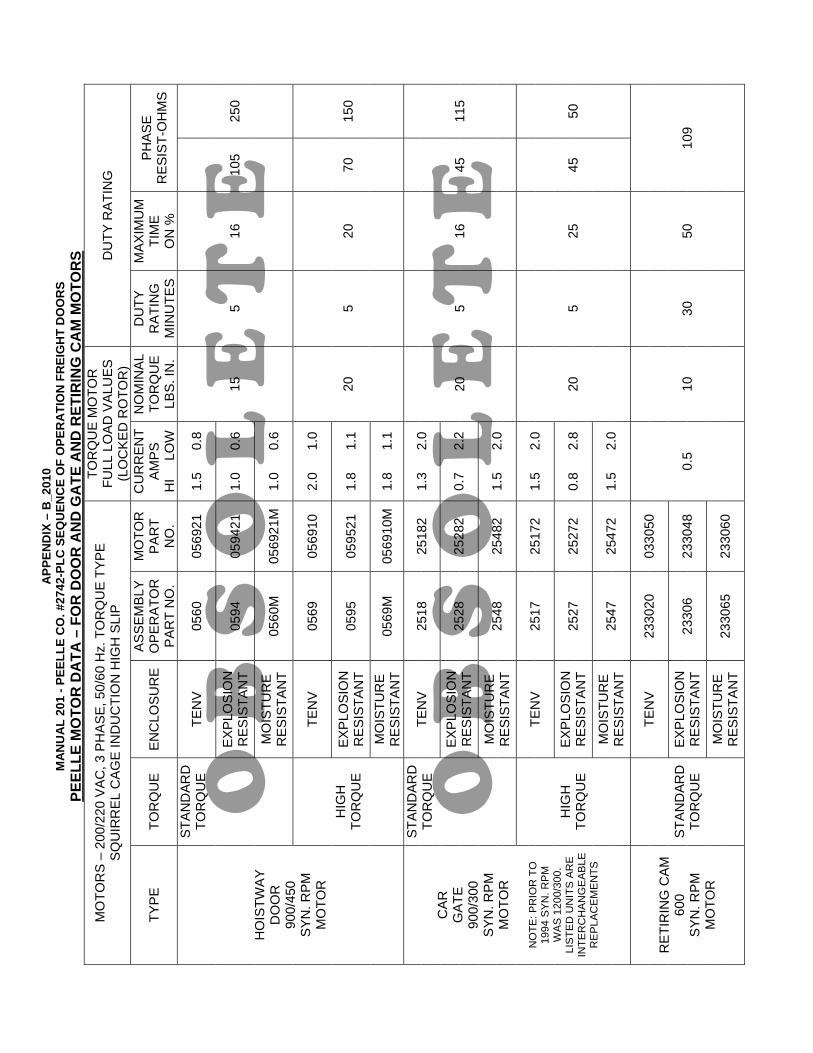
A
PPEN
DIX
– B
_201
0 M
AN
UA
L 20
1 - P
EELL
E C
O. #
2742
-PLC
SEQ
UEN
CE
OF
OPE
RA
TIO
N F
REI
GH
T D
OO
RS
O B
S O
L E
T E
O B
S O
L E
T E
PEEL
LE M
OTO
R D
ATA
– F
OR
DO
OR
AN
D G
ATE
AN
D R
ETIR
ING
CA
M M
OTO
RS
MO
TOR
S –
200
/220
VA
C, 3
PH
AS
E, 5
0/60
Hz.
TO
RQ
UE
TY
PE
S
QU
IRR
EL
CAG
E IN
DU
CTI
ON
HIG
H S
LIP
TOR
QU
E M
OTO
R
FULL
LO
AD
VA
LUE
S
(LO
CK
ED
RO
TOR
) D
UTY
RA
TIN
G
TYP
E
TOR
QU
E
EN
CLO
SU
RE
ASSE
MBL
Y O
PER
ATO
RP
AR
T N
O.
MO
TOR
P
AR
T N
O.
CU
RR
ENT
AMPS
H
I
LOW
NO
MIN
AL
TOR
QU
E
LBS.
IN.
DU
TY
RA
TIN
G
MIN
UTE
S
MA
XIM
UM
TIM
E
ON
%
PH
AS
E
RE
SIS
T-O
HM
S
TEN
V 05
60
0569
21
1.5
0
.8
EXPL
OSI
ON
R
ES
ISTA
NT
0594
05
9421
1.
0
0.6
STA
ND
ARD
TO
RQ
UE
MO
ISTU
RE
R
ES
ISTA
NT
0560
M
0569
21M
1.0
0
.6
15
5 16
10
5 25
0
TEN
V 05
69
0569
10
2.0
1
.0
EXPL
OSI
ON
R
ES
ISTA
NT
0595
05
9521
1.
8
1.1
HO
ISTW
AY
D
OO
R
900/
450
SY
N. R
PM
M
OTO
R
HIG
H
TOR
QU
E M
OIS
TUR
E
RE
SIS
TAN
T 05
69M
05
6910
M1.
8
1.1
20
5 20
70
15
0
TEN
V 25
18
2518
2 1.
3
2.0
EXPL
OSI
ON
R
ES
ISTA
NT
2528
25
282
0.7
2
.2
STA
ND
ARD
TO
RQ
UE
MO
ISTU
RE
R
ES
ISTA
NT
2548
25
482
1.5
2
.0
20
5 16
45
11
5
TEN
V 25
17
2517
2 1.
5
2.0
EXPL
OSI
ON
R
ES
ISTA
NT
2527
25
272
0.8
2
.8
C
AR
G
ATE
90
0/30
0 S
YN
. RP
M
MO
TOR
NO
TE: P
RIO
R T
O
1994
SYN
. RP
M
WA
S 1
200/
300.
LI
STE
D U
NIT
S A
RE
IN
TER
CH
AN
GE
AB
LE
RE
PLA
CE
ME
NTS
HIG
H
TOR
QU
E M
OIS
TUR
E
RE
SIS
TAN
T 25
47
2547
2 1.
5
2.0
20
5 25
45
50
TEN
V 23
3020
03
3050
EXPL
OSI
ON
R
ES
ISTA
NT
2330
6 23
3048
R
ETI
RIN
G C
AM
600
SY
N. R
PM
M
OTO
R
STA
ND
ARD
TO
RQ
UE
MO
ISTU
RE
R
ES
ISTA
NT
2330
65
2330
60
0.5
10
30
50
109

TECHNICAL SUPPORT1-800-787-5020 ext 275
NORTH AMERICAN [email protected]
EXPORT [email protected]
FREIGHT DOORS I CAR GATES I CAR ENCLOSURESTHE PEELLE COMPANY
®


![PEELLE Guide 200 spanish:Layout 1 - Peelle Doors · Se presenta una lista de indicadores de entrada del PLC [Indicador 0CH 00] para facilitar la localización de fallas. 1.1 INTERRUPTOR](https://img.pdfslide.net/doc/110x75/613981a2a4cdb41a985bbc1b/peelle-guide-200-spanishlayout-1-peelle-doors-se-presenta-una-lista-de-indicadores.jpg)