Embed Size (px)
Citation preview

Isı Bilimi ve Tekniği Dergisi, 36, 1, 107-118, 2016
J. of Thermal Science and Technology
©2016 TIBTD Printed in Turkey ISSN 1300-3615
1
THE PERFORMANCE ANALYSIS OF A SILICA GEL/WATER ADSORPTION
CHILLER AND DYNAMIC HEAT AND MASS TRANSFER CHARACTERISTICS OF
ITS ADSORBENT BED: A PARAMETRIC STUDY
Billel MEBARKİ*, İsmail SOLMUŞ**, Rabah GOMRİ*** * Faculty of Engineering, Department of Génie Climatique, Constantine University
25000 Constantine – Algeria, [email protected] **
Department of Mechanical Engineering, Atatürk University
25240 Erzurum, Turkey, [email protected] *** Laboratory of Génie Climatique, Faculty of Engineering, Department of Génie Climatique, Constantine
University, 25000 Constantine Algeria, [email protected]
(Geliş Tarihi: 27.07.2015, Kabul Tarihi: 13.01.2016)
Abstract: The performance of two adsorbent bed silica gel-water adsorption chiller and the influences of its
adsorbent bed dimensions, the velocity of heat exchange fluid and the adsorbent particle diameter on the transient
distributions of the solid phase temperature, adsorbate concentration and the pressure are numerically examined in
this study. A transient two-dimensional local thermal non-equilibrium model that takes into account both internal and
external mass transfer resistances is developed to simulate the adsorption chiller considered herein. The internal and
external mass transfers are predicted by the linear driving force (LDF) model and Darcy’s equation, respectively. It is
found that an increase in the adsorbent particle diameter results in the decrease in both the coefficient of performance
(COP) and specific cooling power (SCP) of the adsorption chiller. On the other hand, the system performance is
nearly independent from the variation of velocity of heat exchange fluid. An increase in the bed thickness leads to an
increase in COP and a decrease in the SCP. The influence of adsorbent bed length on the performances of system can
be neglected. The results of our simulations provide useful guidelines for the design of this type of adsorption chillers.
Keywords: Adsorption, Cooling, Silica gel/water, LDF, LTNE, COP
ADSORPSİYONLU SİLİKA JEL/SU SOĞUTMA SİSTEMİNİN PERFORMANS
ANALİZİ VE ADSORBAN YATAĞININ DİNAMİK ISI VE KÜTLE TRANSFERİ
DAVRANIŞI: PARAMETRİK ÇALIŞMA
Özet: İki adsorban yataklı silika jel/su çalışma çiftini kullanan adsorpsiyonlu soğutma sisteminin performansı ve
sistemin adsorban yatak boyutlarının, ısı değiştirici akışkan hızının ve adsorban tanecik çapının zamana bağlı olarak
katı fazın sıcaklık dağılımı, adsorplanan konsantrasyonu ve basınç dağılımı üzerine etkileri sayısal olarak bu
çalışmada incelenmiştir. Zamana bağlı iki boyutlu ve lokal olarak ısıl dengenin olmadığı iç ve dış kütle transfer
dirençlerini dikkate alan sayısal bir model söz konusu sistemi incelemek için geliştirilmiştir. İç ve dış kütle transfer
dirençleri sırasıyla doğrusal itici güç modeli ve Darcy denklemi vasıtasıyla hesaplanmıştır. Parametrik çalışma
neticesinde artan adsorban tanecik çapının sistemin performans katsayısı ve özgül soğutma gücü üzerinde bir düşüşe
yol açtığı bulunmuştur. Diğer taraftan, sistem performansının ısı değiştirici akışkan hızının değişiminden neredeyse
bağımsız olduğu elde edilmiştir. Adsorban yatak kalınlığındaki bir artış sistemim performans katsayısında
yükselmeye ve özgül soğutma gücünde ise düşüşe yol açmıştır. Adsorban yatak uzunluğunun sistem performansı
üzerine olan etkisi ihmal edilebilecek düzeydedir. Parametrik çalışmamızın sonuçları bu tip adsorpsiyonlu soğutma
sistemlerinin tasarımı için faydalı öneriler ortaya koymaktadır.
Anahtar Kelimeler: Adsorpsiyon, Soğutma, Silika Jel/Su, LDF, LTNE, COP
Nomenclature
av Area of gas–solid interface per unit volume
[1/m]
Cp Specific heat [ J/(kgK)]
De Equivalent diffusivity in the adsorbent
particles [m2/s]
Do
Reference diffusivity [m2/s]
dp Average diameter of the adsorbent particle
[m]
Ea Activation energy of surface diffusion
[J/mol]
H Convective heat transfer coefficient between
the adsorbent bed and cooling fluid
[W/(m2K)]
hg Interfacial convective heat transfer
108
coefficient [W/(m2K)]
hm_ads Convective heat transfer coefficient between
adsorbent bed and the metallic wall
[W/(m2K)]
K Permeability [m2]
km Mass transfer coefficient within the
adsorbent particles [1/s]
K Thermal conductivity [W/(mK)]
L Length of the adsorbent bed [m]
Ls Latent heat of evaporation [J/kg]
Nud Nusselt number
P Pressure [kPa]
Pr Prandtl number
Q Heat of adsorption [J/kg]
R Universal gas constant [J/(molK)]
Red Reynolds number
Rg Specific gas constant for water vapor
[J/(kgK)]
R1 Inner diameter of the metallic wall [m]
R2 Outer diameter of the metallic wall [m]
R3 Outer diameter of the adsorbent bed [m]
r Radial coordinate [m]
T Temperature [K]
t Time [s]
u Gas phase velocity in radial direction [m/s]
v Gas phase velocity in axial direction [m/s]
X Adsorbate concentration [kgw/kgad]
Equilibrium adsorption capacity [kgw/kgad]
z Axial coordinate [m]
Greek symbols
μ Viscosity [Ns/m2]
ρ Density [kg/m3]
ɛt Total porosity
ɛb Bed porosity
ɛp Particle porosity
λg -e Effective thermal conductivity for the gas
phase [W/(mK)]
λs -e Effective thermal conductivity for the solid
phase [W/(mK)]
λm Thermal conductivity of metallic wall
[W/(mK)]
λf Thermal conductivity of heat exchange fluid
[W/(mK)]
Subscripts
co Condenser
e Evaporator
f Heat exchange fluid
g Gas phase
i Initial
m Metallic wall
re Regeneration
s Solid phase
sat Saturation
INTRODUCTION
The environmental-friendly adsorption cooling (AC)
systems are an attractive alternative to the traditional
vapor-compression cooling systems as they are
characterized by their low operation and maintenances
costs, simple control and the absence of vibration and
corrosion problems (Anyanwu, 2000). AC systems can
be powered by a low grade heat source such as solar,
waste heat or geothermal. Although the AC systems
have these advantages, their drawbacks are the
intermittent operation, the requirements of special
designs to maintain high vacuum, the large volume and
weight relative to traditional refrigeration systems, the
low specific cooling power (SCP) and the low
coefficient of performance (COP) (Anyanwu, 2003). On
the other hand, the poor heat and mass transfer within
the adsorbent bed are vital to the development and
application of the adsorption refrigeration technology
(Wang et al., 2010). Hence, an enhancement on the heat
and mass transfer conditions inside the adsorbent bed
leads to a more efficient system (Anyanwu, 2003). This
can be accomplished by using an adsorbent-adsorbate
working pair with a high cyclic adsorption capacity and
thermal conductivity and a low resistance to adsorbate
flow as well as a better heat management during the
adsorption cycle. As a result, adsorption cooling
systems have attracted much research attention in recent
years.
Thermodynamic investigation on the multi bed
adsorption chiller using silica gel-water is carried out by
several researchers (Ahmed et al., 2012; Lu and Wang,
2013; Mitra et al., 2014). Although some valuable
results are presented in these studies, the proposed
models are only focus on the COP values of the systems
without providing any information about the transient
heat and mass transfer processes. Most of the models
proposed previously for heat transfer within the
adsorbent bed are based on the Local Thermal
Equilibrium (LTE) assumption. It means that there is a
thermal equilibrium between the gas and solid phases
and hence, single energy equation is sufficient to
describe the temperature fields of gas and solid phases.
However, local thermal equilibrium assumption cannot
be used in some circumstances (Duval et al., 2004).
Mhimid (1998) studied the heat and mass transfer in a
zeolite bed during water desorption using the local
thermal equilibrium and local thermal non-equilibrium
models and the results showed that the local thermal
equilibrium assumption is not valid in regions with high
rates of heat transfer. Jemni and Nasrallah (1995)
investigated transient heat and mass transfer in a metal-
hydrogen reactor and they concluded that the local
thermal equilibrium model is not valid in the whole
reactor. Therefore, it is considered that local thermal
equilibrium model may not lead to realistic results so
two equation model (Local Thermal Non-Equilibrium
model) taking into account the heat transfer between the
phases is employed in this study.
The mass transfer inside the adsorbent bed is described
by two mechanisms, i.e., internal and external mass
transfer. Adsorbate flows from a solid adsorbent
particle surface to inner points of the particle and
through the voids between the solid adsorbent particles
are called internal and external mass transfer,
109
respectively. The internal mass transfer can be evaluated
by the Linear Driving Force (LDF) or Solid Diffusion
(SD) models. However if the resistance to internal mass
transfer is insignificant, adsorption equilibrium can be
considered without leading to remarkable deviation
from the reality and most of published studies assume
adsorption equilibrium. The external mass transfer is
typically predicted by Ergun’s and Darcy’s equation.
The external mass transfer resistance is often ignored
and a uniform pressure is employed. The Darcy’s
equation is used in the present study due to low velocity
of gas phase within the adsorbent bed (Wu et al., 2009).
The some of previous studies are classified in Table 1
according to proposed model for heat and mass transfer,
working pair and model dimension.
Table 1. Classification of proposed models in term of their characteristics
Ref. Dimension Internal
Mass
Transfer
External Mass
Transfer
Energy
Equation
Working Pair
[12,17,18] 2D LDF Darcy’ law LTE Zeolit13X/Water
[4,5,6,15,30] Lumped LDF Uniform
pressure
Uniform
temperature
Silica gel/Water
[13] 2D Adsorption
equilibrium
Uniform
pressure
LTE Active carbon/ Ammonia
[14] 1D LDF Uniform
pressure
LTE Active carbon/ Methanol
[11,16,21,29] 1D Adsorption
equilibrium
Uniform
pressure
LTE Active carbon/ Ammonia
[19,20,23] 2D LDF Darcy’s law LTNE Silica gel/Water
[22] 2D LDF Uniform
pressure
LTE Jiangxi AC809/ Methanol
[26,27] 3D LDF Darcy’s law LTE Zeolithe 13x/water
[28] 3D LDF Darcy’s law LTE Carbon active methanol
In this study, a two dimensional local thermal non
equilibrium model is proposed for heat transfer. The
external and internal mass transfer resistances are taken
into account by linear driving force model (LDF) and
Darcy’s law, respectively. The effect of design and
operating parameters on the performances of two
adsorbent bed chiller using silica gel water and
distributions of solid phase temperature, adsorbate
concentration and the pressure inside the adsorbent bed
are presented. The simulation result will provide useful
information for the design and transient operation of
these kinds of chillers.
MATHEMATICAL MODEL
The proposed mathematical model is based on two
dimensional approach with the local thermal non
equilibrium between the phases. In this model, the
internal and external mass transfer resistances are taken
into account by linear driving force model and Darcy’s
law, respectively. A schematic view of the adsorbent
bed is presented in Fig 1. The adsorbent bed is a hollow
cylinder which encloses a metal tube for the purpose of
heat exchange between the solid adsorbent and the
heating or cooling fluid within the tube. The proposed
model is based on the following assumptions:
The adsorbed phase is considered as a liquid and
the adsorbate gas is assumed to be an ideal gas.
The adsorbent bed is composed of uniform-size
particles.
Physical properties such as thermal conductivities,
specific heat capacities and viscosity are not a
function of temperature.
The thermal resistance between the metal tube and
the adsorbent bed is neglected.
The pressure in condenser or evaporator during the
entire adsorption cycle is assumed to be constant.
Fig. 1 Schematic diagram of the adsorbent bed
The energy conservation equation for the thermal-fluid
is:
110
(1)
The energy conservation equation for the metal tube is given by:
(2)
The energy conservation equation for the solid phase of the adsorbent can be written as:
(3)
The energy conservation equation for the gas phase can be given by:
(4)
The overall mass conservation in the adsorbent bed is given by:
(5)
The linear driving force (LDF) model is used for
describing the adsorption rate (Sakoda and Suzuki,
1984):
(6)
Where is the adsorbed phase concentration in
equilibrium and can be written as (Di et al., 2007):
(7)
is the internal mass transfer coefficient given by:
(8)
is the equivalent diffusivity in the adsorbent particles
which is expressed as:
(9)
The fluid–solid specific surface area for spherical
particles is determined by:
(10)
The interfacial heat transfer coefficient for the spherical
particle is evaluated by:
(11)
The effective thermal conductivity for the solid and gas
phases can be defined as follows:
(12)
(13)
The volume fraction of the gas phase is assumed to be
equal to the total porosity, and may be evaluated
using:
(14)
The velocities of adsorbate in the r and z directions
inside the adsorbent bed are determined as follows:
(15)
(16)
Here K is the permeability which can be calculated by
the following semi-empirical Blake-Kozeny equation:
(17)
The heat of adsorption as function of X can be defined
by the following equations:
(18)
(19)
111
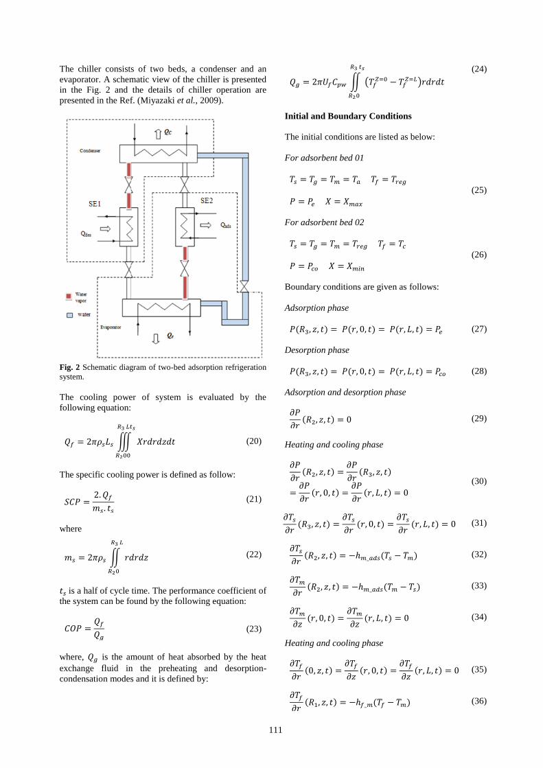
The chiller consists of two beds, a condenser and an
evaporator. A schematic view of the chiller is presented
in the Fig. 2 and the details of chiller operation are
presented in the Ref. (Miyazaki et al., 2009).
Fig. 2 Schematic diagram of two-bed adsorption refrigeration
system.
The cooling power of system is evaluated by the
following equation:
(20)
The specific cooling power is defined as follow:
(21)
where
(22)
is a half of cycle time. The performance coefficient of
the system can be found by the following equation:
(23)
where, is the amount of heat absorbed by the heat
exchange fluid in the preheating and desorption-
condensation modes and it is defined by:
(24)
Initial and Boundary Conditions
The initial conditions are listed as below:
For adsorbent bed 01
(25)
For adsorbent bed 02
(26)
Boundary conditions are given as follows:
Adsorption phase
(27)
Desorption phase
(28)
Adsorption and desorption phase
(29)
Heating and cooling phase
(30)
(31)
(32)
(33)
(34)
Heating and cooling phase
(35)
(36)
112
(37)
Here is the convective heat transfer coefficient
between the heat exchange fluid and the metallic wall
and it is defined by the following equation
(38)
NUMERICAL PROCEDURE
The nonlinear coupled governing partial differential
equations under consideration are solved numerically
using the finite difference technique. The central
differencing, first order upwind scheme, and forward
differencing are used to discretize the second order
spatial derivatives, convective, and unsteady terms,
respectively. The resulting set of nonlinear algebraic
equations is solved iteratively by the combination of the
alternating direction implicit (ADI) method, the
Newton–Raphson iteration scheme and a block
tridiagonal matrix solver algorithm (Thomas algorithm).
The influence of the number of grid points and time
steps on the solid phase temperature at nearly thermal
equilibrium case and various locations in the
computational domain is shown in Table 2. It can be
seen from Table 2 that the difference between the
results obtained for three different grid sizes (40×10),
(15×10) and (30×20) and time steps (0.02, 0.04, 0.1 and
1 s) are quite small. Therefore, the number of grid
points and the time step are chosen to be (30×20) and
0.02s, respectively to ensure the reliability of the
numerical computations. The convergence criterion
used in the simulation program is 10-6
.
Table 2. The effect of grid size and time step on the solid phase temperature
∆t=0.02 sec ∆t=0.04 sec
R(m), z(m) 40×10 30×20 15×10 40×10 30×20 15×10
0.023, 0 327.8206 327.8081 327.6185 327.8202 327.8584 327.6688
0.031, 0.175 338.6148 338.5191 338.3353 338.5090 338.5254 338.3430
0.036, 0.35 339.1587 339.1487 339.1432 339.1587 338.1505 339.1419
∆t=0.1 sec ∆t=1 sec
R(m), z(m) 40×10 30×20 15×10 40×10 30×20 15×10
0.023, 0 327.8215 327,8465 327.7017 327.8313 327.8584 327.6688
0.031, 0.175 338.5124 338.5229 338.4242 338.5651 338.5254 338.3430
0.036, 0.35 339.1587 339.1514 339.1446 339.1591 338.1505 339.1419
RESULTS AND DISCUSSIONS
A computer simulation program based on the numerical
procedure above is written in MatLab to perform the
parametric investigation. The base parameters used in the
simulations are listed in Table 3. The effect of adsorbent bed
thickness, velocity of the heat exchange fluid, adsorbent bed
length and adsorbent particle diameter on the distributions of
the solid phase temperature, adsorbate concentration and
pressure during the adsorption process as well as the
performance of the system are discussed below.
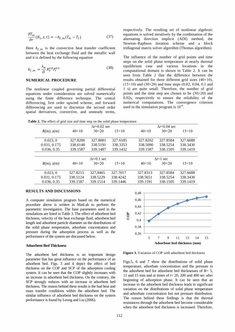
Adsorbent Bed Thickness
The adsorbent bed thickness is an important design
parameter that has great influence on the performance of an
adsorbent bed. Figs. 3 and 4 depict the effect of bed
thickness on the COP and SCP of the adsorption cooling
system. It can be seen that the COP slightly increases with
an increase in adsorbent bed thickness. On the contrary, the
SCP strongly reduces with an increase in adsorbent bed
thickness. The reason behind these results is the bad heat and
mass transfer conditions within the adsorbent bed. The
similar influence of adsorbent bed thickness on the system
performance is found by Leong and Liu (2006).
Figure 3. Variation of COP with adsorbent bed thickness
Figs.5, 6 and 7 show the distributions of solid phase
temperature, adsorbate concentration and the pressure in
the adsorbent bed for adsorbent bed thicknesses of R= 5,
11 and 15 mm and at times of t= 20, 200 and 400 sec after
beginning of adsorption phase. It can be seen that an
increase in the adsorbent bed thickness leads to significant
variation on the distributions of solid phase temperature
and adsorbate concentration but not pressure distribution.
The reason behind these findings is that the thermal
resistances through the adsorbent bed become considerable
when the adsorbent bed thickness is increased. Therefore,
0,36
0,38
0,4
0,42
0,44
0,46
0,48
5 7 9 11 13 14 15
CO
P
Adsorbent bed thickness (mm)

113
increasing adsorbent bed thickness results in an increase in
the cycle time. The adsorbent bed thickness should be kept
as smaller as possible to reduce the cycle time and as a
result of this, an enhancement on the specific cooling
power can be achieved.
Figure 4. Variation of SCP with adsorbent bed thickness.
Table 3. The base parameters used in the simulations.
Parameter Value Unit
Cpg 1800 J /kgK
Cps 924 J/ kgK
Dp 1.4e-3 m
Do 2.54e-4 m2/ s
Ea 4.2e4 J /mol
kg 0.024 W/mK
ks 0. 198 W/mK
L 0.35 m
Pco 4.246 kPa
Pe 1.228 kPa
R3 0.036 m
R2 0.021 m
R1 0.02 m
Tcon 40 °C
Treg 90 °C
ɛb 0.37
ɛp 0.64
μg 1.5e-5 kg /ms
ρs 2027 kg /m3
ρm 2700 kg /m3
Cpm 900 J /kgK
km 237 W/mK
ρf 1000 kg /m3
Cpf 4180 J /kgK
kf 0.6 W/mK
Uf 0.6 m/s
Figure 5. The influence of adsorbent bed thickness on the
distribution of solid phase temperature.
Figure 6. The influence of adsorbent bed thickness on the
distribution of adsorbate concentration in the adsorbent bed.
Figure 7. The influence of adsorbent bed thickness on the
distribution of pressure.
0
10
20
30
40
50
60
70
80
90
5 7 9 11 13 14 15
SC
P(W
/kg
)
Adsorbent bed thickness (mm)
114
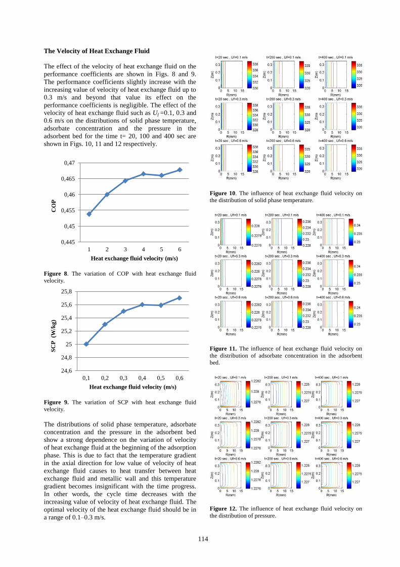
The Velocity of Heat Exchange Fluid
The effect of the velocity of heat exchange fluid on the
performance coefficients are shown in Figs. 8 and 9.
The performance coefficients slightly increase with the
increasing value of velocity of heat exchange fluid up to
0.3 m/s and beyond that value its effect on the
performance coefficients is negligible. The effect of the
velocity of heat exchange fluid such as Uf =0.1, 0.3 and
0.6 m/s on the distributions of solid phase temperature,
adsorbate concentration and the pressure in the
adsorbent bed for the time t= 20, 100 and 400 sec are
shown in Figs. 10, 11 and 12 respectively.
Figure 8. The variation of COP with heat exchange fluid
velocity.
Figure 9. The variation of SCP with heat exchange fluid
velocity.
The distributions of solid phase temperature, adsorbate
concentration and the pressure in the adsorbent bed
show a strong dependence on the variation of velocity
of heat exchange fluid at the beginning of the adsorption
phase. This is due to fact that the temperature gradient
in the axial direction for low value of velocity of heat
exchange fluid causes to heat transfer between heat
exchange fluid and metallic wall and this temperature
gradient becomes insignificant with the time progress.
In other words, the cycle time decreases with the
increasing value of velocity of heat exchange fluid. The
optimal velocity of the heat exchange fluid should be in
a range of 0.1–0.3 m/s.
Figure 10. The influence of heat exchange fluid velocity on
the distribution of solid phase temperature.
Figure 11. The influence of heat exchange fluid velocity on
the distribution of adsorbate concentration in the adsorbent
bed.
Figure 12. The influence of heat exchange fluid velocity on
the distribution of pressure.
0,445
0,45
0,455
0,46
0,465
0,47
1 2 3 4 5 6
CO
P
Heat exchange fluid velocity (m/s)
24,6
24,8
25
25,2
25,4
25,6
25,8
0,1 0,2 0,3 0,4 0,5 0,6
SC
P (W
/kg
)
Heat exchange fluid velocity (m/s)
115
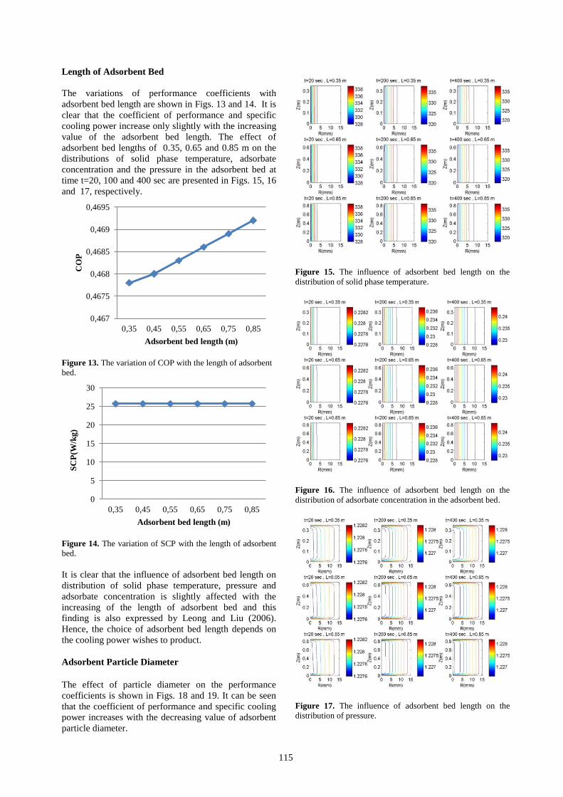
Length of Adsorbent Bed
The variations of performance coefficients with
adsorbent bed length are shown in Figs. 13 and 14. It is
clear that the coefficient of performance and specific
cooling power increase only slightly with the increasing
value of the adsorbent bed length. The effect of
adsorbent bed lengths of 0.35, 0.65 and 0.85 m on the
distributions of solid phase temperature, adsorbate
concentration and the pressure in the adsorbent bed at
time t=20, 100 and 400 sec are presented in Figs. 15, 16
and 17, respectively.
Figure 13. The variation of COP with the length of adsorbent
bed.
Figure 14. The variation of SCP with the length of adsorbent
bed.
It is clear that the influence of adsorbent bed length on
distribution of solid phase temperature, pressure and
adsorbate concentration is slightly affected with the
increasing of the length of adsorbent bed and this
finding is also expressed by Leong and Liu (2006).
Hence, the choice of adsorbent bed length depends on
the cooling power wishes to product.
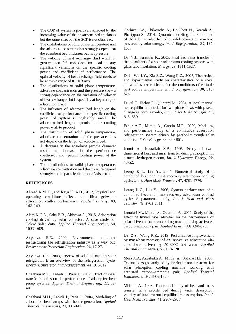
Adsorbent Particle Diameter
The effect of particle diameter on the performance
coefficients is shown in Figs. 18 and 19. It can be seen
that the coefficient of performance and specific cooling
power increases with the decreasing value of adsorbent
particle diameter.
Figure 15. The influence of adsorbent bed length on the
distribution of solid phase temperature.
Figure 16. The influence of adsorbent bed length on the
distribution of adsorbate concentration in the adsorbent bed.
Figure 17. The influence of adsorbent bed length on the
distribution of pressure.
0,467
0,4675
0,468
0,4685
0,469
0,4695
0,35 0,45 0,55 0,65 0,75 0,85
CO
P
Adsorbent bed length (m)
0
5
10
15
20
25
30
0,35 0,45 0,55 0,65 0,75 0,85
SC
P(W
/kg
)
Adsorbent bed length (m)
116
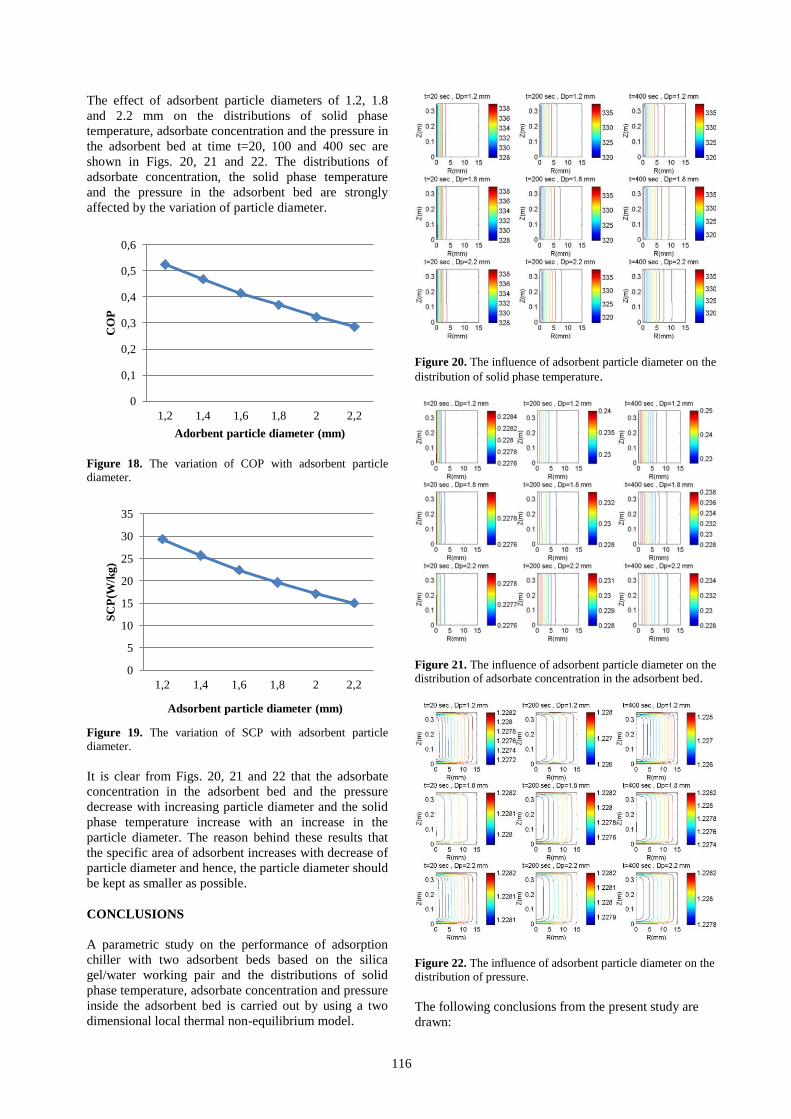
The effect of adsorbent particle diameters of 1.2, 1.8
and 2.2 mm on the distributions of solid phase
temperature, adsorbate concentration and the pressure in
the adsorbent bed at time t=20, 100 and 400 sec are
shown in Figs. 20, 21 and 22. The distributions of
adsorbate concentration, the solid phase temperature
and the pressure in the adsorbent bed are strongly
affected by the variation of particle diameter.
Figure 18. The variation of COP with adsorbent particle
diameter.
Figure 19. The variation of SCP with adsorbent particle
diameter.
It is clear from Figs. 20, 21 and 22 that the adsorbate
concentration in the adsorbent bed and the pressure
decrease with increasing particle diameter and the solid
phase temperature increase with an increase in the
particle diameter. The reason behind these results that
the specific area of adsorbent increases with decrease of
particle diameter and hence, the particle diameter should
be kept as smaller as possible.
CONCLUSIONS
A parametric study on the performance of adsorption
chiller with two adsorbent beds based on the silica
gel/water working pair and the distributions of solid
phase temperature, adsorbate concentration and pressure
inside the adsorbent bed is carried out by using a two
dimensional local thermal non-equilibrium model.
Figure 20. The influence of adsorbent particle diameter on the
distribution of solid phase temperature.
Figure 21. The influence of adsorbent particle diameter on the
distribution of adsorbate concentration in the adsorbent bed.
Figure 22. The influence of adsorbent particle diameter on the
distribution of pressure.
The following conclusions from the present study are
drawn:
0
0,1
0,2
0,3
0,4
0,5
0,6
1,2 1,4 1,6 1,8 2 2,2
CO
P
Adorbent particle diameter (mm)
0
5
10
15
20
25
30
35
1,2 1,4 1,6 1,8 2 2,2
SC
P(W
/kg
)
Adsorbent particle diameter (mm)
117
The COP of system is positively affected by the
increasing value of the adsorbent bed thickness
but the same effect on the SCP is not observed.
The distributions of solid phase temperature and
the adsorbate concentration strongly depend on
the adsorbent bed thickness but not pressure.
The velocity of heat exchange fluid which is
greater than 0.3 m/s does not lead to any
significant variations on the specific cooling
power and coefficient of performance. The
optimal velocity of heat exchange fluid needs to
be within a range of 0.1-0.3 m/s
The distributions of solid phase temperature,
adsorbate concentration and the pressure show a
strong dependence on the variation of velocity
of heat exchange fluid especially at beginning of
adsorption phase.
The influence of adsorbent bed length on the
coefficient of performance and specific cooling
power of system is negligibly small. The
adsorbent bed length depends on the cooling
power wish to product.
The distribution of solid phase temperature,
adsorbate concentration and the pressure does
not depend on the length of adsorbent bed.
A decrease in the adsorbent particle diameter
results an increase in the performance
coefficient and specific cooling power of the
system.
The distributions of solid phase temperature,
adsorbate concentration and the pressure depend
strongly on the particle diameter of adsorbent.
REFERENCES
Ahmed R.M. R., and Raya K. A.D., 2012, Physical and
operating conditions effects on silica gel/water
adsorption chiller performance, Applied Energy, 89,
142–149.
Alam K.C.A., Saha B.B., Akisawa A., 2015, Adsorption
cooling driven by solar collector: A case study for
Tokyo solar data, Applied Thermal Engineering, 50,
1603-1609.
Anyanwu E.E., 2000, Environmental pollution:
restructuring the refrigeration industry as a way out,
Environment Protection Engineering, 26, 17-27.
Anyanwu E.E., 2003, Review of solid adsorption solar
refrigerator I: an overview of the refrigeration cycle,
Energy Conversion and Management, 44, 301-312.
Chahbani M.H., Labidi J., Paris J., 2002, Effect of mass
transfer kinetics on the performance of adsorptive heat
pump systems, Applied Thermal Engineering, 22, 23-
40.
Chahbani M.H., Labidi J., Paris J., 2004, Modeling of
adsorption heat pumps with heat regeneration, Applied
Thermal Engineering, 24, 431-447.
Chekirou W., Chikouche A., Boukheit N., Karaali A.,
Phalippou S., 2014, Dynamic modeling and simulation
of the tubular adsorber of a solid adsorption machine
powered by solar energy, Int. J. Refrigeration, 39, 137-
151.
Dai Y.J., Sumathy K., 2003, Heat and mass transfer in
the adsorbent of a solar adsorption cooling system with
glass tube insulation, Energy, 28, 1511-1527.
Di J., Wu J.Y., Xia Z.Z., Wang R.Z., 2007, Theoretical
and experimental study on characteristics of a novel
silica gel-water chiller under the conditions of variable
heat source temperature, Int. J. Refrigeration, 30, 515-
526.
Duval F., Fichot F., Quintard M., 2004, A local thermal
non-equilibrium model for two-phase flows with phase-
change in porous media, Int. J. Heat Mass Transfer, 47,
613–639.
Fadar A.E., Mimet A., Garcia M.P., 2009, Modeling
and performance study of a continuous adsorption
refrigeration system driven by parabolic trough solar
collector, Solar Energy, 83, 850-861.
Jemni A., Nasrallah S.B., 1995, Study of two-
dimensional heat and mass transfer during absorption in
a metal-hydrogen reactor, Int. J. Hydrogen Energy, 20,
43-52.
Leong K.C., Liu Y., 2004, Numerical study of a
combined heat and mass recovery adsorption cooling
cycle, Int. J. Heat Mass Transfer, 47, 4761-4770.
Leong K.C., Liu Y., 2006, System performance of a
combined heat and mass recovery adsorption cooling
cycle: A parametric study, Int. J. Heat and Mass
Transfer, 49, 2703-2711.
Louajari M., Mimet A., Ouammi A., 2011, Study of the
effect of finned tube adsorber on the performance of
solar driven adsorption cooling machine using activated
carbon–ammonia pair, Applied Energy, 88, 690-698.
Lu Z.S., Wang R.Z., 2013, Performance improvement
by mass-heat recovery of an innovative adsorption air-
conditioner driven by 50-80°C hot water, Applied
Thermal Engineering, 55, 113-120.
Mers A.A, Azzabakh A., Mimet A., Kalkha H.E., 2006,
Optimal design study of cylindrical finned reactor for
solar adsorption cooling machine working with
activated carbon–ammonia pair, Applied Thermal
Engineering, 26, 1866-1875.
Mhimid A., 1998, Theoretical study of heat and mass
transfer in a zeolite bed during water desorption:
validity of local thermal equilibrium assumption, Int. J.
Heat Mass Transfer, 41, 2967-2977.
118
Mitra S., Kumar P., Srinivasan K., Dutta P., 2014,
Simulation study of a two-stage adsorber system,
Applied Thermal Engineering, 72, 283-288.
Miyazaki T., Akisawa A., Saha B.B., El-Sharkawy I.I.,
Chakraborty A., 2009, A new cycle time allocation for
enhancing the performance of two-bed adsorption
chillers, Int. J. Refrigeration, 32, 846-853.
Sakoda A., Suzuki M., 1984, Fundamental study on
solar power adsorption cooling system, Journal of
Chemical Engineering of Japan, 17, 52-57.
Solmuş İ., Rees D.A.S., Yamalı C., Baker D., 2012, A
two-energy equation model for dynamic heat and mass
transfer in an adsorbent bed using silica gel/water pair,
Int. J. Heat and Mass Transfer, 55, 5275-5288.
Solmuş İ., Rees D.A.S., Yamalı C., Baker D.,
Kaftanoğlu B., 2012, Numerical investigation of
coupled heat and mass transfer inside the adsorbent bed
of an adsorption cooling unit, Int. J. Refrigeration, 35,
652-662.
Solmuş İ., Yamalı C., Yıldırım C., Bilen K., 2015,
Transient behavior of a cylindrical adsorbent bed during
the adsorption Process, Applied Energy, 142, 115-124.
Solmuş İ., Yıldırım C., 2014, Adsorpsiyonlu bir
soğutma sisteminin performansının farklı çalışma
çiftleri için teorik analizi, Journal of Thermal Science
and Technology, 34, 29-37.
Wang D.C., Li Y.H., Li D., Xi Y.Z. and Zhang J.P.,
2010, A review on adsorption refrigeration technology
and adsorption deterioration in physical adsorption
systems, Renewable and Sustainable Energy Reviews,
14, 344-353.
Wu W.D., Zhang H., Sun D.W., 2009, Mathematical
simulation and experimental study of a modified zeolite
13X–water adsorption refrigeration module Applied
Thermal Engineering, 29, 645-651.
Zhang L.Z., 2000, A three dimensional non-equilibrium
model for an intermittent adsorption cooling system,
Solar Energy, 69, 27-35.
Zhang L.Z., Wang L., 1999, Effects of coupled heat and
mass transfers in adsorbent on the performance of a
waste heat adsorption cooling unit, Applied Thermal
Engineering, 19, 195-215.
Zhang X.J., Liu H.X., Wang R.Z., Shi F., 2002,
Numerical simulation of heat transfer in regenerator of
solid adsorption refrigeration system, Renewable
Energy, 26, 599-610.


![Study of a novel silica gel¨Cwater adsorption chiller[1]. Part I. Design and perfor mance prediction](https://img.pdfslide.net/doc/110x75/577cd96a1a28ab9e78a37313/study-of-a-novel-silica-gelcwater-adsorption-chiller1-part-i-design-and.jpg)


![krishna.nic.in/PDFfiles/MSME/Chemical/ SILICA GEL [1].pdfkrishna.nic.in/PDFfiles/MSME/Chemical/SILICA GEL[1].pdf · SILICA GEL CONTENTS SECTION I PRODUCT CHARACTERISTICS AND SPECIFICATION](https://img.pdfslide.net/doc/110x75/5aa0c4717f8b9a7f178e9479/silica-gel-1pdf-gel1pdfsilica-gel-contents-section-i-product-characteristics.jpg)