Embed Size (px)
Citation preview

B
A
R
L
D
d
the poweris yours!
11/2
010
Q serieshousing
input shaft
quadrant
worm
stroke adjustment
indicator
coating

Q series
performance specifications
--> 14 Models--> Up to 70.000 Nm. Torque range--> -5° to 95° stroke--> IP68 sealing--> -25 °C to +110 °C (-13 °F to +230 °F) temperature range
The Pro-Gear Series “Q “ quarter turn gearboxes are rugged, industrial grade products, manufactured with cast iron housing and components. All models in this series feature high performance bearings and a powder coated finish.
applications
The Q series is highly suitable for all general industrial applications as well as applications in chemical, power, HVAC and waterworks. Pro-Gear’s operators are intended for the operation of ball, plug and butterfly valves as well as power and process dampers. The usage of high grade of materials provides a tough, reliable unit for the automation of today’s high performance industrial valves. Several options such as padlocking devices, memory stops, spur gears and limit switchboxes can be eassily mounted on site without any machining, due to the inte gration of all necessary connections on the housing.
features
--> Stainless Steel input shaft--> Stainless Steel fasteners --> Standarised according to DIN / ISO 5211--> 13 Models up to 70.000 Nm. output--> Axial needle bearings--> NBR 70 gasket material--> Sealed position-indicator--> Powder coated / polyurethane coated finish--> Insert bush system for flexibility and reduced lead times
(interchangeable with X-series inserts)--> Carefully choosen ratio’s are increasing the MA-rates--> Blind tapped PCD’s
type ratiotorQue (Nm) m.a.
± 10%weiGht(kg)output input
Q-200 S 40 : 1 200 16.8 11.9 2
Q-400 S 44 : 1 400 31.25 12.8 3.87
Q-800 S 40 : 1 800 60 13.3 7.68
Q-1500 S 42 : 1 1500 122.95 12.2 13.50
Q-2000 S 48 : 1 2000 131 15.3 14.55
Q-3000 S 62 : 1 3000 167 17.9 22.8
Q-4000 S 72 : 1 4000 185 21.6 31.5
Q-6500 S 267 : 1 6500 95 68.4 37.50
Q-12000 S 267 : 1 12000 168.48 71.2 56.70
Q-16000 S 648 : 1 16000 120 133.3 62.50
Q-24000 S 720 : 1 24000 140 171.4 192
Q-32000 S 960 : 1 32000 140 228.6 195
Q-50000 S 960 : 1 50000 150 333.3 352
Q-70000 S 1280 : 1 70000 185 378.4 352
1Nm=0,737562 lbf.ft. 1Nm=8,8507 lbf.ins. [Converting International Units to British Units]

the po
wer i
s you
rs!
parts / materials list Q series
part no description material specs / standard
1 Body Cast-iron / Ductile iron GG25/ASTM A48
2 Coverplate Cast-iron GG25/ASTM A48
3 Pos. Indicator Cast-iron GG25/ASTM A48
4 Quadrant Ductile-iron GGG40 / ASTM A356
5 Worm Carbon steel C45-K
6 Shaft Stainless steel
7 Axial needle bearing
8 Gasket Nitrile/silicone NBR-70° shore
9 O-rings Nitrile NBR-70° shore
10 Grease Complex EP-0 DIN KGOG0.5N-30 ISO-L-XCDIB0.5
11 Fasteners Stainless steel
Gearbox type a b b d d h h l r ValVe connection acc iso 5211
Q-200 SMM 43.5 70 84 4 12 28.5 64 118 - 50 (F05) 70 (F07)INCH 1.71 2.76 3.31 0.16 0.47 1.12 2.52 4.65 - 1.97 2.76
Q-400 SMM 52.5 91 112 4 12 34 74.75 175 - 70 (F07) 102 (F10)INCH 2.07 3.58 4.41 0.16 0.47 1.34 2.94 6.89 - 2.76 4.02
Q-800 SMM 68.75 110 135 5 15 42.5 90.5 225 - 102 (F10) 125 (F12) 140 (F14)INCH 2.71 4.33 5.31 0.20 0.59 1.67 3.56 8.86 - 4.02 4.92 5.51
Q-1500 SMM 84 129 156 6 20 45 97 214 - 102 (F10) 125 (F12) 140 (F14)INCH 3.31 5.08 6.14 0.24 0.79 1.77 3.82 8.43 - 4.02 4.92 5.51
Q-2000 SMM 96.5 150 180 6 20 50 100 240 - 102 (F10) 125 (F12) 140 (F14) 165 (F16)INCH 3.80 5.91 7.09 0.24 0.79 1.97 3.94 9.45 - 4.02 4.92 5.51 6.50
Q-3000 SMM 117.5 201 250 6 20 48.5 117.5 255 - 140 (F14) 165 (F16)INCH 4.63 7.91 9.84 0.24 0.79 1.91 4.63 10.04 - 5.51 6.50
Q-4000 SMM 137.5 210 282 6 20 54.5 128 300 - 165 (F16) 254 (F25)INCH 5.41 8.27 11.10 0.24 0.79 2.15 5.04 11.81 - 6.50 10.00
Q-6500 SMM 137.5 210 282 6 20 54.5 128 347 222 165 (F16) 254 (F25)INCH 5.41 8.27 11.10 0.24 0.79 2.15 5.04 13.66 8.74 6.50 10.00
Q-12000 SMM 180 272 366 6 20 63.5 135 378 282 254 (F25) 298 (F30)INCH 7.09 10.71 14.41 0.24 0.79 2.50 5.31 14.88 11.10 10.00 11.73
Q-16000 SMM 180 272 366 8 25 63.5 135 403 326 254 (F25) 298 (F30)INCH 7.09 10.71 14.41 0.31 0.98 2.50 5.31 15.87 12.83 10.00 11.73
Q-24000 SMM 252.5 350 510 8 25 85 186 442 365 254 (F25) 298 (F30) 356 (F35) 406 (F40)INCH 9.94 13.78 20.08 0.31 0.98 3.35 7.32 17.40 14.37 10.00 11.73 14.02 15.98
Q-32000 SMM 252.5 350 510 8 25 85 186 442 365 254 (F25) 298 (F30) 356 (F35) 406 (F40)INCH 9.94 13.78 20.08 0.31 0.98 3.35 7.32 17.40 14.37 10.00 11.73 14.02 15.98
Q-50000 SMM 291.5 540 612 key 8mm 25 138 262.5 612 502 356 (F35) 406 (F40) 483 (F48)INCH 11.48 21.26 24.09 0.31" key 0.98 5.43 10.33 24.09 19.76 14.02 15.98 19.02
Q-70000 SMM 291.5 540 612 key 8mm 25 138 262.5 612 502 356 (F35) 406 (F40) 483 (F48)INCH 11.48 21.26 24.09 0.31" key 0.98 5.43 10.33 24.09 19.76 14.02 15.98 19.02
B
A
R
L
D
d
b
hH
L
d
D
B
A
1
9
8
2
9
3
6
4
5
7
10b
hH
L
d
D
BA
1
9
8
2
9
3
6
4
5
7
10
Q series
11/2
010
Kopenhagener Straße 21D-48455 Bad Bentheim - GildehausTel +49 (0)5924 255 840 - Fax +49 (0)5924 255 841E-mail [email protected] - www.pro-gear.de
the power is yours!
Pro-Gear GmbH is a young, highly flexible team, who are carrying out every element of design, assembly and quality control with the utmost care.
The unique combination of the products, together with the know how and assembling facilities are creating for clients a relationship, unique in the valve actuator industries. GOST certificated
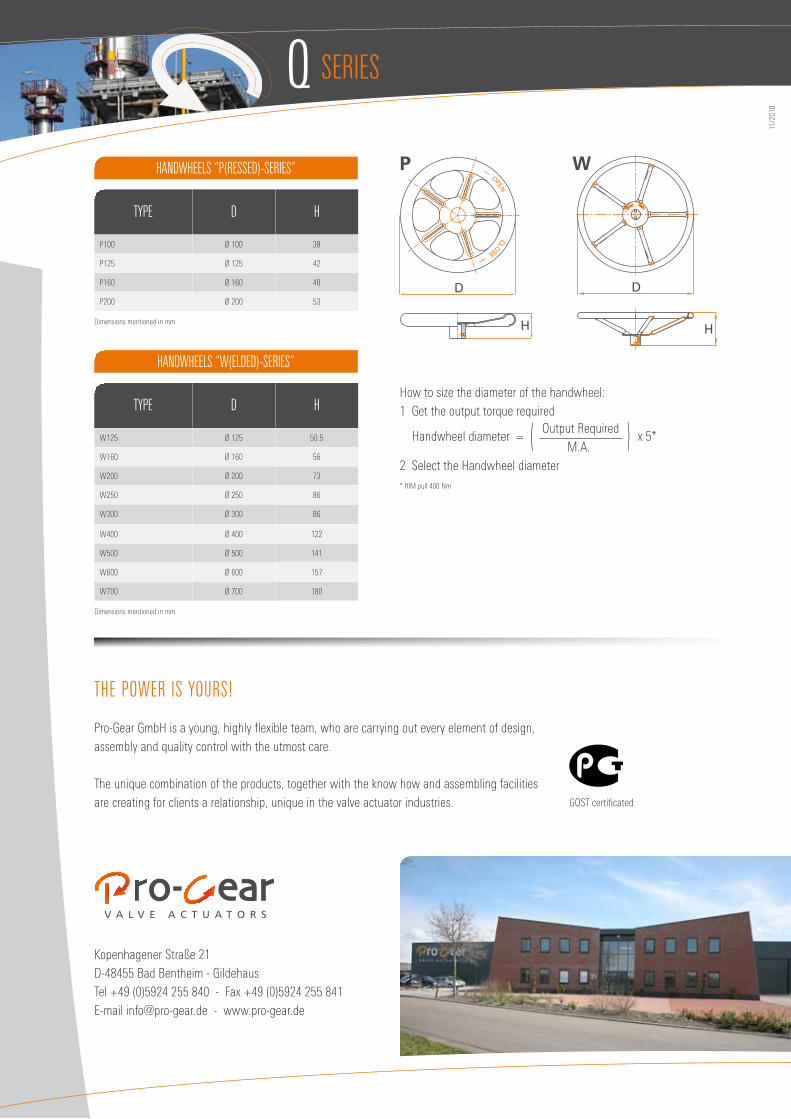
handwheels “p(ressed)-series”
handwheels “w(elded)-series”
type d h
P100 Ø 100 38
P125 Ø 125 42
P160 Ø 160 48
P200 Ø 200 53
Dimensions mentioned in mm.
type d h
W125 Ø 125 50.5
W160 Ø 160 56
W200 Ø 200 73
W250 Ø 250 86
W300 Ø 300 86
W400 Ø 400 122
W500 Ø 500 141
W600 Ø 600 157
W700 Ø 700 180
Dimensions mentioned in mm.
H
D
OPEN
CLOSE
H
D
How to size the diameter of the handwheel: 1 Get the output torque required
Handwheel diameter = Output Required
x 5* ( M.A. )2 Select the Handwheel diameter* RIM pull 400 Nm
P W