Embed Size (px)
Citation preview

Department of Agriculture Ministry of Agriculture and Forest The Kingdom of Bhutan
THE PREPARATORY SURVEY REPORT
ON
THE PROJECT FOR IMPROVEMENT OF
TAKLAI IRRIGATION SYSTEM IN
SARPANG DISTRICT
IN
THE KINGDOM OF BHUTAN
November 2012
JAPAN INTERNATIONAL COOPERATION AGENCY
SANYU CONSULTANTS INC
RD
JR
12-093
No.

PREFACE
Japan International Cooperation Agency (JICA) decided to conduct “The
Preparatory Survey on the Project for Improvement of Taklai Irrigation System in
Sarpang District in the Kingdom of Bhutan” and entrust the survey to Sanyu
Consultants Inc.
The survey team held a series of discussions with the officials concerned of the
government of the Kingdom of Bhutan, and conducted a field investigation. As a
result of further studies in Japan, the present report was finalized.
I hope that this report will contribute to the promotion of the project and to the
enhancement of friendly relations between our two countries.
Finally, I wish to express my sincere appreciation to the officials concerned of the
Government of the Kingdom of Bhutan for their close cooperation extended to the
survey team.
November, 2012
Teruyoshi KUMASHIRO
Director General,
Rural Development Department
Japan International Cooperation Agency

i
Summary
1. Introduction
Agricultural sector in Kingdom of Bhutan is the key industry which employs 69% of Bhutan’s population and occupies 14% of GDP. It has a substantial share of the country’s rural poor population, so that poverty reduction is placed as the top priority in the National Development Plan. However, Bhutan is totally a mountainous country. Agricultural land occupies only 7.7 % of the country’s land. Furthermore, each agricultural land holding area and each farm plot of farmers are limited to small size, due to terrace farming in the steep topography.
The Gross National Happiness Commission (GNHC) formulated the 10th five year national development plan in 2009, which is currently being used as guide. The target of the national plan was to secure the stable and robust macroeconomic framework by central policy of social development and poverty alleviation. In addition, it aims at self-reliant finance, good accounting balance, restraining of inflation and soundness of foreign debt, which are controlled by efficient public investment.
In the mid-term review of the 10th five year plan conducted, it was mentioned in report, that rice self-sufficiency is expected to improve by 55% until 2013 which is end of year the plan.
The 11th five year plan is now being drafted. The GNHC prepared a guideline that sets the overall goal as “Self-Reliance and Inclusive Green Socio-Economic Development”.
In regard to the entire economic status in Bhutan, the acquisition of foreign currency is generated by the tourism industry. The other source of revenue is from the development of hydraulic power generation (financed by the Indian Government) getting profit from selling electric power. Therefore average economic growth rate increased from 9% in 2002 to 2008 to 11.8% in 2010. The Gross National Income (GNI) per person in Bhutan is US$ 2,070 (sourced from World Bank 2011). The Gross Domestic Product (GDP) of structural rate for each category in 2010 is electric power sector: 17.6%, agriculture and forest: 16.8%, construction: 8.7%, industry: 2.2%, service business: 36.5%.
2. Back ground of the project
Taklai Irrigation Scheme, the largest irrigation system in Bhutan located in Sarpang district is considered as the key irrigation system serving for the important production area in the south part of the country. This irrigation system was completed in the 1980’s with having due support by United Nations World Food Program (WFP), United Nations Development Program (UNDP) and others. The system was planned aiming at double cropping of rice, as of construction completion ,for the 1,300 Ha beneficiary areas for 756 farm households, whereas, 883 Ha beneficiary areas for approx. 530 farm households as of 2011. Largely, the system can be divided into two (2) parts, one served by high level canal and the other by low level canal. It is expected that attaining enlarged rice cropping in dry season through restoring the subject irrigation system function will greatly contribute to raising up of self-sufficiency ratio of rice at the national level and also to improvement of agricultural productivity in Sarpang district.
However, those existing intake facilities and main canals of the system have been suffering from flood damages almost every year, due to its being located near the Taklai River, which changed its river water route so often. Furthermore, it is noteworthy to mention, that the repair cost for the incurred damages is considered a big burden to the responsible agency. Also, repair works remain at provisional level only. Considering the present situation, it would seem to be difficult to consider a

ii
stable and quantitatively adequate irrigation water supply. In addition, the flood that occurred in September 2010 heavily damaged the existing intake facilities and main canal to an extent never experienced before. For the said damages, the government is trying to implement emergency rehabilitation works partly on the system. However, there is a need to urgently undertake comprehensive rehabilitation works for the intake facilities in a sustainable manner for higher durability of the system.
3. Outline of the project and study
The purpose of the project study is to improve and restore the functionality of Taklai irrigation system, the largest irrigation are in Bhutan, and contribute in the increase in rice self-sufficiency and expansion of agricultural productivity in the area.
And the project is formed by discussion with Bhutanese based on the request letter from Bhutanese and result of site survey, in addition, the planned project components are same as written items in request letter, there is no any additional or cancel items. Site survey schedule were as follow;
The first site survey : Middle of January 2012~ Middle of February 2012 (31 days)
The second site survey : Middle of September 2012~ End of September 2012 (10 days)
Table:Outline of the project components Item of facility Description
1. Integrated headwork ・Fixed Weir:L 38.9m x 1.0m ・Bed protection:L= 30.0m
2. Head race and sedimentation basin
・Box culvert:L= 358.9m ・Open canal:L= 631.2m ・Sedimentation Basin:L= 37.5m ・Retaining wall:H 3.9m x L 410m
3. Link canal ・Rise up wall:L= 654.6m ・Improvement:L= 109.6m
4. Confluence between Link canal and Low level intake
・L type retaining wall H 2m x L 4.65m ・Newly constructing gate:One (1) gate
5. High Level canal
・Wet masonry:L= 123.7m ・Rise up wall:L=165m ・Covered by concrete:L= 205.8m ・Rehabilitation of leakage at 2nd siphon outlet:Covered by concrete・Rehabilitation of leakage at aqueduct:L=50m ・Safe fence around siphon:6 nos. ・Improvement of siphon:covered by reinforce concrete ・Concrete bridge:re-construction (width 4m) x 2 bridges
6. Exposed siphon pipe on High Level Canal ・Protection of exposed siphon pipe at 3rd siphon L= 45m
7. Gate on High and Low Level Canal ・High Level Canal : Check and distribution gate:10gates ・Low Level Canal : Check gate:2gates
8. Water gauge at integrated headwork ・Water gauge:Sound wave type 1 set
9. Protection dike at downstream of Taklai River
・Dike:W 4.0m x H3.0m x L 340m ・Retaining wall:H 3.9m x L 340m
10. Soft component ・ Instruction and assistance for operation of facility, water management, maintenance

iii
(1) Overall goal and project purpose
As a overall goal of this project, National Development Tenth Five-Year Plan (2008-2013) is a guiding
plan of Bhutan related to this Project. From agricultural point of view, Ministry of Agriculture and
Forests (MoAF) has provided strategic programs for strengthening markets, marketing and production
of agricultural products for the purpose of ensuring food security and alleviating rural poverty.
Concretely, 29 programs have been implemented through the initiative and in charge of MoAF, by
which the following impacts are expected in terms of agriculture:
① Improving self-sufficiency ratio of rice from 50% to 59%,
② Increasing the level of annual farm-income from Nu10,700 to Nu35,000 and
③ Reducing the rate of local population stratum below poverty line from 30.9% to 20%.
“Contribution to the realization of double-cropping of rice in the target beneficiary area” is considered
as the overall goal of this Project. Also, as regards the Project purpose, it aims at “enabling to
supply irrigation water to the initially targeted area planned in Taklai Irrigation System”.
This system has the largest beneficiary area in irrigation projects in Bhutan (over 1,000 ha) and the only one nationally-managed project. This Project is expected to serve as a model scheme in Bhutan because synergetic effect can be realized between this Project and nationally implemented canal rehabilitation scheme by the reason that rehabilitation of existing canals has been implemented as a national strategy with the objective of expanding the scale of dry-season irrigation, thus enabling stable water supply throughout the year, thereby targeting to mitigate poverty rate and to promote higher farm income, also by the reason that larger scale of project output can be anticipated by its large impact since it has larger project area than the scale of perimeter in other district (about 200ha).
In order to fulfill the above-mentioned overall goal and the project purpose, it is indispensable to realize stable water intake and water supply with permanently functioning facilities in which climatic change (abnormal scale of flood etc) are taken into consideration in its design, and it is also essential to combine new-construction and rehabilitation of irrigation facilities by hard component with the capacity improvement of maintaining and managing them by soft component.
(2) Basic policy
In formulating the Project, the position, the effects, technical and economic feasibility/ relevance of Japanese Grant Aid toward the implementation of this Project are to be verified, thereby essential and optimum design of the planned facilities is provided for obtaining proper fruit/ outputs of the Project.
Basic principles applied to the facility design include integrating the existing water-intake system of diverting water at two intakes at upstream (High Level Canal : H.L.C) and downstream (Low Level Canal : L.L.C) sites into an integrated head works, satisfying the capacity of the facility to convey planned water quantity by this integration, also repairing/ rehabilitating facilities of the existing irrigation system the irrigation functions of which have been damaged and deteriorated/ dilapidated.
To provide the structure of the integrated head works with sufficient strength that will be constructed at the upstream of the existing H.L.C intake with stabilized river-bed and that allows to take the totaled water quantity of both existing H.L.C and L.L.C sites. Irrigation water thus taken into the canal will be distributed at its existing downstream diversion points according to the water requirement for each

iv
irrigation area. The stable supply of irrigation water is pursued by estimating irrigation water requirement and flood discharges to be planned in the Project and strengthening a part of head race by newly constructing culvert structure with reinforced concrete that will be connected to the existing main canal at H.L.C site.
(3) Policies applied to natural/ environmental conditions
・ Flood discharge
1,710m3/s is adopted as the design discharge that has been calculated from 1/50 year’s probable
rainfall which based on the record at Bhur Observatory Station. In this regard, this value is larger than
the maximum recorded flood discharge in the past estimated from the observed flood vestiges.
・ Drought discharge
Annually probable discharge at the site of the planned head works is estimated at around 1.12m3/s
from the observation result available in and around the site. Since this value is evidently lower than
design irrigation water requirement, 2.24m3/s as shown below, it is considered possible that in the
course of probability evaluation drought discharge corresponded to 50% of the design water
requirement appear every year.
Yet, a discharge of about 3.8m3/s has been observed at the planned site of the head works during the
study team was in February, or during dry season, and the interviewed persons in this study told that
such a level of discharge as observed during the study was seen every year in the interview survey.
Considering these situations, each facility is designed based on 2.24m3/s, required irrigation water
quantity, however, taking account of some possibility of evolving water-deficit years failing to satisfy
the planned water supply, such practices as rotational irrigation and time-limited irrigation covering all
blocks in a day is planned to cope with such possibility.
・ Geology at the planned site of head works
Geological formation in and around the planned site of head works can roughly be classified into gravel and pebbles over the stream-bed and quartzite / gneissic boulder derived from volcanic origin materials judging from the result of a geologic survey. Both of these strata are relatively compact judging from the measurement results with 35° or larger for their internal friction angle and about 2.0tf/m3 as unit weight.
Therefore an apron of head works is designed as floating type because the foundation is conceived high permeable strata.
(4) Farming and irrigational (on-farm) conditions
As this Project has main objective of functional recovery for Taklai Irrigation System through new construction of integrated head works and head race as well as rehabilitation of main canal and appurtenant structures etc, farming environment of the beneficial farmers will be improved as a result of enabling stable supply of irrigation water.
As far as crop selection has basically been kept at farmer’s own disposal without any policy intervention, it is predicted that some farmers surely try to be engaged in spring crops (dry-season

v
cropping) with paddy and wheat once stable supply of irrigation water is realized.
No radical change is brought in the operation and maintenance of terminal irrigation facilities and sharing system of water management (operation of water-gates).
(5) Policies applied to socio-economic situations
It is considered that the rehabilitation of Taklai Irrigation System and subsequent improvement in farming conditions contribute to beneficiary farmer’s increased food production and their livelihood improvement, leading to favorable impact to local economy. In so far as this Project has the objective of rehabilitating the existing Taklai Irrigation System, it won’t bring any new large-scaled development in the area. It follows that living customs and traditions of the beneficiaries will be conserved as they are now.
Further, from gender point of view, men and women used to share farm labor/ practices within household or community, hence it is considered that expansion of cropping area would not result in an increased burden for women only.
(6) Policies towards management and operation/ maintenance
A soft component is provided for realizing of following capacity improvement targets as a supporting
activity, thus assisting to obtain required knowledge and techniques and to sustain operation and
maintenance.
・Because no permanent facility exists that doesn’t need any maintenance / management, operation
and maintenance techniques should be mastered with the preventive and conservative ideas in
order to keep as long life as possible of the facilities that are newly constructed or rehabilitated by
this Project,
・Pertinent method of water management (operation of gates) should be trained in order to make
improved capacity of the facilities fully functioning.
(7) Policies on the establishment of the grade of the planned facilities
The facilities of Taklai Irrigation System shall be designed by adopting the following parameters,
based on natural and environmental conditions and the planned scale of the target area:
・Design water intake: 2.24 m3/s (maximum intake quantity)
・Design flood discharge: 1,710 m3/s(probable flood discharge of once in 50 years; 1/50)
Based on the Taklai river that facilities should be planned under hard natural conditions as observed in
this case, it is considered relevant from the economic point of view to allow some degree of possible
damages to such extent that it will not reach to a serious damage by mitigating the natural action,
rather than directly resisting against evolving natural forces, What is important is the establishment of
proper and regular maintenance to sustain the project facilities over a long period of time instead of
providing excessive or large- scale of facilities.
For the facilities to be constructed outside of the river such as canal, the same policy is applied to
repair and rehabilitation works, considering that the possibility of proper maintenance by Bhutanese
vi
can lead to long-term operation of functions of the facilities
4. Project implementation schedule and estimation of project cost
The project implementation schedule is shown as below;
・Detailed design : approx. four (4) months ・Bidding and contract for construction : approx. two and half (2.5) months ・Construction works : approx. 21months
The project cost to be borne by the Bhutanese side is estimated to be about 9 million JPY.
5. Project evaluation
(1) Relevance
The number of beneficiaries is approximately 4,300 while household is 530. The farmer's income in this area is approximately US$ 390 (17,700 Nu ) per household. While GNI (Gross National Income) is US$ 2,070 per person in Bhutan, is means that the target area’s income is approximately one-fifth of national level. The farmers account for the majority of population in the area, therefore almost people are considered at the lower level than national level in Bhutan. Accordingly, the number of poor is higher in this area.
In the 10th five-year national development plan for Bhutan, the target was to reduce the ratio of poverty from 23.2 % (2007) to 15%. In addition, as there are many poor people in the rural area, rural integrated development is categorized as one of the important area for development. In addition, increase in self-sufficiency of crops is an urgent issue due to the geological condition in Bhutan therefore the aim is to increase self-sufficiency from 50% of the current rate to 59 % until 2018.
The largest irrigation system in Sarpang District in Bhutan, the Taklai irrigation system, considered as the productive crucial are in south Bhutan, is expected to contribute to the improvement of national self -sufficient of rice and agricultural production in this area with the expansion of cropped area in dry season by restraining of irrigation system facility.
The 11th five-year national development plan also plans in preparation to improve agricultural infrastructure, expansion of the irrigation area and increase farmer's income, hence the implementation of this project is expected to become a model project on agricultural development in Bhutan.
A mutual concern between Bhutan and Japan, since the establishment of diplomatic relations on 28th March in 1986, is to have structured friendly relations through the exchanges between imperial and royal family and economic support such as instruction of agriculture promotion. Therefore Japan is considered as country that can provide ODA support and assistance to Bhutan, while Bhutan is considered as the important for Japan as it provides support and espousal on election or resolution at international agency to Japan.
The major emphasis for Bhutan based on Japanese policies are as follows; ① Agricultural and rural development (mechanization of agriculture, improvement of agricultural infrastructure ), ②Improvement of economic foundation (road networks, electrification of rural area, diffusion of information ), ③Social development (strengthening of the educational service, strengthening of

vii
medical and health services, development of human resources for the job creation), ④ Good governance (decentralization). In this project, ① Agricultural and rural development (mechanization of agriculture, improvement of agricultural infrastructure) are included as part of the project therefore the project conforms to policy of Japan.
In addition, according to the achievement of Millennium Development Goals (MDGs) of United Nations (UN), support to “Human security" is a crucial policy that is being promoted. The project also promotes the development and improvement of agricultural productivity to increase crop self-sufficiency The Project therefore contribute to the policy " Eradicate Extreme Poverty & Hunger" which is one of the development policy on MDGs,
Bhutan advocates Gross National Happiness (GNH) as the central priority for the national plan, which does not pursue the physical or economic improvement but spiritual improvement.. This idea is focused as though it would overcome a deadlock and cooped-up feeling of the society which has given priority to development of economical efficiency, and the examination in order to introduce the idea of GNH into a new indicator for MDGs is beginning at UN, now. Accordingly, to contribute the national policy based on GNH in Bhutan expects to contribute the achievement of MDGs
(2) Effectiveness
The expected impact of the implementation of the project is as follows;
・ Quantitative effects Table: Indicator for the Quantitative effects
Items Base year(2012) Target year(2018) Remarks Irrigation water supply in dry season
0 m3/s max. 2.24 m3/s *1) enable to supply irrigation water by construction of head works
Irrigation area 883 ha max. 1,120 ha*2) enable to supply irrigation water by rehabilitation of damaged siphon
Paddy area in dry season
10 ha 560 ha
expand the double crop area by supplied stable water in dry season. as the condition of assumptions, the cropping pattern of irrigation area in dry season is divided to vegetable and rice by a half respectively.
Annual maintenance cost
ave.3,500,000 Nu 1,750,000 Nu alleviation of rehabilitation works for the headrace canal and protection wall by gabions
※Target year is three years later after the construction
*1) Maximum planned irrigation water is considered of probability that drought discharge of Taklai river by
examined probable rainfall might be lower than planned irrigation water, 2.24 m3/s.
*2) Actual registered house hold and beneficiaries is approximately 530 and 4,300 respectively. Those are
expected to receive the benefit directly.
・ Qualitative effects
① The farmer's income will increase with the increase in rice production and better selling price.
② With the inclusion of soft component activity, there will be improvement of O &M skills and techniques. Also, collection of data and sharing of information will contribute to keep the good condition of the irrigation facility.
③ O & M activities in Taklai irrigation system will be good model and extended to other similar

viii
area.
④ through extension of rice double crop, the operating rate of machine for agricultural works which is not used during fallow periods will increase.
⑤ The direct effect of disaster prevention for irrigation area or facility will be expected by construction of river dike; in addition, reinforcement of existing protection wall and new construction of intake or delivery canal with good durability will bring the stabilization of irrigation facility on flood period and, accordingly, contribute to raising up rice production and farmer's income.

CONTENTS
Preface
Summary
Contents
Location Map / Perspective
List of Figures & Tables
Abbreviations
Units
Chapter 1 BACKGROUND OF THE PROJECT........................................................ 1-1
1-1 Introduction ................................................................................................................... 1-1
1-2 Outline of the preparatory survey ................................................................................... 1-1
1-3 Agriculture...................................................................................................................... 1-2
1-3-1 Land Ownership .................................................................................................... 1-2
1-3-2 Crops ..................................................................................................................... 1-3
1-3-3 Rice Production ..................................................................................................... 1-3
1-3-4 Utilization of Agricultural Machinery and Animal Draft Power........................... 1-4
1-3-5 Role of Female and Male on Rice Production and Work Sharing ........................ 1-5
1-3-6 Marketing .............................................................................................................. 1-5
1-3-7 Agricultural Extension........................................................................................... 1-6
1-3-8 Agricultural Associations and Cooperatives ......................................................... 1-7
1-4 Natural condition .......................................................................................................... 1-8
1-4-1 Topographic, Geological and Climatic classification ............................................ 1-8
1-4-2 Meteorological condition at Taklai Irrigation Area ............................................... 1-8
1-4-3 Hydrological condition at the site of head works .................................................. 1-11
1-4-4 Effects of earthquake ............................................................................................. 1-14
1-4-5 Geological survey .................................................................................................. 1-14
1-4-6 Topographic survey ............................................................................................... 1-15
1-5 Environmental and Social Consideration ...................................................................... 1-15
1-5-1 Preparation and submission of IEE Report.............................................................. 1-15
1-5-2 Procedure for securing environmental approval .................................................... 1-15
1-5-3 Environmental Impact Assessment ....................................................................... 1-15
1-5-4 Elaboration of impact-mitigating measures ........................................................... 1-24
1-5-5 Monitoring Plan and Environmental Checklist ..................................................... 1-25
1-5-6 Stakeholder’s Meeting ........................................................................................... 1-26
1-5-7 Land acquisition and resettlement ......................................................................... 1-26
1-5-7-1 Necessity of land acquisition and resettlement ................................................ 1-26
1-5-7-2 Legal framework for land acquisition and resettlement ................................... 1-26

1-5-7-3 The range of area for land acquisition and resettlement .................................. 1-26
1-5-7-4 The detailed measurement for compensation and support ............................... 1-26
1-5-7-5 The way of complaint management ................................................................. 1-26
1-5-7-6 Implementation agency for the resettlement and responsibility ....................... 1-26
1-5-7-7 Implementation schedule .................................................................................. 1-26
1-5-7-8 Finance and budget .......................................................................................... 1-26
1-5-7-9 Monitoring and monitoring form by executive agency .................................... 1-26
1-5-7-10 Meeting of residence ........................................................................................ 1-26
1-5-8 Draft monitoring form ........................................................................................... 1-26
1-5-9 Check list of environment ..................................................................................... 1-26
Chapter 2 CONTENTS OF THE PROJECT................................................................ 2-1
2-1 Basic Concept of the Project........................................................................................... 2-1
2-2 Outline design of the requested Japanese assistance ...................................................... 2-2
2-2-1 Design Policy .............................................................................................................. 2-2
2-2-1-1 Basic policy.......................................................................................................... 2-2
2-2-1-2 Policies applied to natural/ environmental conditions ......................................... 2-4
2-2-1-3 Farming and irrigational (on-farm) conditions..................................................... 2-5
2-2-1-4 Policies applied to socio-economic situations...................................................... 2-5
2-2-1-5 Policies on the situations of construction / procurement...................................... 2-6
2-2-1-6 Policies on the utilization of local constructors (construction firms)................... 2-6
2-2-1-7 Policies towards management and operation/ maintenance ................................. 2-6
2-2-1-8 Policies on the establishment of the grade of the planned facilities..................... 2-7
2-2-1-9 Policies concerning work method/procurement method and construction period ..... 2-7
2-2-2 Basic plan (Construction plan/Equipment plan).......................................................... 2-8
2-2-2-1 Design irrigation water requirement .................................................................... 2-8
2-2-2-2 Design of the integrated head works .................................................................... 2-10
2-2-2-3 Design of head race.............................................................................................. 2-34
2-2-2-4 Reinforcement of the existing gabion wall .......................................................... 2-42
2-2-2-5 Protection dike at the downstream of Taklai River.............................................. 2-46
2-2-2-6 Existing main canal and related facilities............................................................. 2-48
2-2-3 Outline design drawing................................................................................................ 2-51
2-2-4 Implementation Plan.................................................................................................... 2-92
2-2-4-1 Implementation policy ......................................................................................... 2-92
2-2-4-2 Implementation conditions................................................................................... 2-94
2-2-4-3 Scope of works..................................................................................................... 2-96
2-2-4-4 Consultant supervision ......................................................................................... 2-97
2-2-4-5 Quality control plan.............................................................................................. 2-99
2-2-4-6 Procurement plan ................................................................................................. 2-99
2-2-4-7 Operational guidance plan.................................................................................... 2-101

2-2-4-8 Soft component (technical assistance) plan......................................................... 2-101
2-2-4-9 Implementation schedule..................................................................................... 2-104
2-3 Obligation of the government of Bhutan ....................................................................... 2-106
2-3-1 Items to be borne by the Bhutanese side on construction division/procurement division 2-106
2-3-2 Items to be borne by the Bhutanese side on the software component plan ................ 2-107
2-3-3 Environmental and social evaluation.......................................................................... 2-107
2-3-3-1 Current situation of procedure to obtain environmental permit for this Project.. 2-107
2-4 Project operation and maintenance plan ........................................................................ 2-107
2-4-1 Project management/ operation and maintenance system .......................................... 2-107
2-4-2 Operation/ Maintenance and Management Plan ......................................................... 2-108
2-5 Estimated project cost .................................................................................................... 2-109
2-5-1 Estimated cost for the project ..................................................................................... 2-109
2-5-1-1 Project cost borne by the Bhutanese side ............................................................ 2-110
2-5-1-2 Cost estimating assumption................................................................................. 2-110
2-5-2 Management, operation and maintenance cost ........................................................... 2-110
Chapter 3 PROJECT EVALUATION........................................................................... 3-1
3-1 Precondition ................................................................................................................... 3-1
3-2 Necessary inputs by the government of Bhutan............................................................. 3-1
3-3 Important assumption..................................................................................................... 3-1
3-4 Project evaluation........................................................................................................... 3-2
3-4-1 Relevance.................................................................................................................... 3-2
3-4-2 Effectiveness............................................................................................................... 3-3
[Appendices]
Appendix-1.Member List of the Study Team............................................................................. A1-1
Appendix-2.Study Schedule....................................................................................................... A2-1
Appendix-3.List of Parties Concerned in the Recipient Country............................................... A3-1
Appendix-4.Minutes of Discussion(M/ D) ........................................................................... A4-1
Appendix-4.1 M/ D on 25th January 2012 .............................................................................. A4-1
Appendix-4.2 M/ D on 19th September 2012 ......................................................................... A4-15
Appendix-5.Soft Component (Technical Assistance) Plan ........................................................ A5-1
Appendix-6.References .............................................................................................................. A6-1
Appendix-6.1 Map of Beneficiary Area................................................................................. A6-1
Appendix-6.2 Calculation of the bar screen on Head works.................................................. A6-2
Appendix-6.3 Calculation of design flood discharge and drought water discharge............... A6-3
Appendix-6.4 A study for the result of Taklai River discharge measurement ....................... A6-9
Appendix-6.5 Summary of WUA workshop on the Taklai Irrigation System....................... A6-10
Appendix-6.6 Summary of Household Survey on the Taklai Irrigation System.................... A6-11
Appendix-6.7 List of Obtaining Document............................................................................ A6-13

Appendix-6.8 Monitoring Plan and Environmental Check List ............................................. A6-18
Appendix-6.9 Estimation of the existing canal section........................................................... A6-23
Appendix-6.10 Environmental Approval .............................................................................. A6-25
Appendix-6.11 Report of geological & soil mechanical investigation ................................... A6-28

・LOCATION M
Gelephu
High level intake (Planed site of
Headwork)
High level canal
Taklai irrigation systems
Taklai irrigation systems
Capital city: Timphu
Site Map of Target area
゚
Gelephu
Location Map
Kingdom of Bhutan
Low level intake
Protection dike at the downstream of
Taklai River
Low level canal
Bhutan
India
Boundary
Taklai river
Exposed part of siphon
Link canal
・LOCATION MAP
Per
spec
tive
T
HE
PR
OJE
CT
FO
R IM
PR
OV
EM
EN
T O
F T
AK
LI I
RR
IGA
TIO
N S
YS
TE
M IN
S
AR
PA
NG
DIS
TR
ICT
IN T
HE
KIN
GD
OM
OF
BH
UT
AN
Link
can
al(R
aise
d up
wal
l and
(r
einf
orce
men
t of b
otto
m)
Inte
grat
ed h
eadw
ork
(Impr
ovem
ent)
Hea
drac
e ca
nal (
Impr
ovem
ent)
Prot
ectio
n di
ke a
t the
dow
nstr
eam
(Im
prov
emen
t)
Takl
ai ri
ver
Low
leve
l can
al
(Reh
abili
tatio
n)
1st S
ipho
n of
hi
gh le
vel c
anal
2nd
Siph
on o
f
high
leve
l can
al
3trd
Sip
hon
of h
igh
leve
l ca
nal (
Reh
abili
tatio
n)
Siph
on o
f
low
leve
l can
al
Hig
h le
vel c
anal
(Reh
abili
tatio
n)

・Site photograph
Photo-1:Aspect of the candidate site of the head works(From the downstream) ・Width of river is narrow and big rocks are exposed on both side.
Photo-2:Existing high level intake ・Service water has been supplied from river through digging canal, but the digging canal is washed away each time a flood occurs.
Photo-3:Full view of existing headrace canal ・There is a headrace canal along the right bank, which is protected by the existing gabion wall. If the gabion wall is damaged, the headrace canal will be also damaged and the supply of water will stop.
Photo-4:Close view of existing headrace canal ・There is a worry about boulder stones into the canal because of the ground on the right side of the photo is close to the canal. (There is also a section where boulder stone occurred.)
Photo-5:Damaged condition of high level canal ・The side wall of canal broke down and was not able to maintain the cross-sectional shape. And parts of breakdown stick in the canal and inhibition of its
photo-6:Check gate in the beneficiary area ・It is a condition that user can not operate because there is no spindle.
FLOW
The candidate site of constructing the head works
Main stream of Taklai River
High level intake
FLOW Existing
gabion wall
Existing headrace canal
FLOW
Damaged part of side wall
Loss of spindle

cross section occurred.
Photo-7:Exposure of existing siphon pipe ・There is a worry about damage for exposed pipe by soils and stones from upstream because this stream changes to river during the rainy season.
Photo-8: Damage of existing siphon pipe ・It is a condition that can not supply water because the body of pipe has been damaged.
Exposed part of siphon

List of Figures & Tables
List of Figures
Page
Figure 1-1 Cropping patterns and cultivated areas in the Taklai Irrigation Scheme............. 1-3
Figure 1-2 Marketing channels for rice production in the Chuzagang area.......................... 1-5
Figure 1-3 Location of meteorology observation stations ................................................... 1-9
Figure 1-4 Meteorological condition (average for last 10 years).......................................... 1-9
Figure 1-5 Annual rainfall and maximum daily rainfall in a year for last 10 years ............ 1-10
Figure 1-6 The ratio of rainfall of each rainy and dry season to annual rainfall ................. 1-10
Figure 1-7 Maximum and minimum temperature ............................................................... 1-11
Figure 1-8 Watershed division and location of river discharge observation station ........... 1-12
Figure 1-9 Maximum flood discharge and water depth in the past ..................................... 1-13
Figure 1-10 Location of Mau, Bhur and Sarpang river........................................................... 1-13
Figure 1-11 Project site ........................................................................................................... 1-16
Figure 1-12 Location between project site, and national protected area
and Biological corridors of Bhutan .................................................... 1-17
Figure 1-13 Procedure of Environmental and Social Considerations ..................................... 1-18
Figure 2-1 Image of integrated intake ................................................................................. 2-2
Figure 2-2 Location map of the cooperation Project............................................................. 2-3
Figure 2-3 Canal network diagram........................................................................................ 2-10
Figure 2-4 Transversal cross section of planned site ............................................................ 2-14
Figure 2-5 Profile of downstream side.................................................................................. 2-14
Figure 2-6 Assumed section of the weir body....................................................................... 2-16
Figure 2-7 Section of screen ................................................................................................. 2-19
Figure 2-8 Required length of bar ......................................................................................... 2-20
Figure 2-9 Section of collecting channel............................................................................... 2-21
Figure 2-10 Range of applying apron protective work ........................................................... 2-33
Figure 2-11 Disposition of existing head race and existing gabion revetment ....................... 2-34
Figure 2-12 Vertical section of the river ................................................................................. 2-34
Figure 2-13 Image figure of dissipating.................................................................................. 2-37
Figure 2-14 Cross section of the dissipater ............................................................................. 2-38
Figure 2-15 Cross section of spillway..................................................................................... 2-39
Figure 2-16 Image of repair of rectangular sectioned open channel in headrace.................... 2-40
Figure 2-17 Water level at design flood discharge and water depth around gabion wall ....... 2-44
Figure 2-18 Relationship between Hm/Hn at meandering part and r/B.................................. 2-45
Figure 2-19 Cross section around gabion revetment............................................................... 2-45
Figure 2-20 Section for calculation......................................................................................... 2-46
Figure 2-21 Location of the planned embankment ................................................................. 2-46

Figure 2-22 Flood water level at around the section of planned Dike .................................... 2-47
Figure 2-23 Typical section of Protection Dike ...................................................................... 2-47
Figure 2-24 Location map of construction work on Taklai Irrigation System........................ 2-92
Figure 2-25 Organization for the Project Implementation ...................................................... 2-93
Figure 2-26 Operation and Maintenance System.................................................................... 2-108
List of Tables
Page
Table 1-1 Outline of the project components .................................................................... 1-2
Table 1-2 No. of agricultural machines(January, 2012) ............................................... 1-5
Table 1-3 Items being observed at meteorology observation station ................................. 1-8
Table 1-4 Trend of annual rainfall and maximum daily rainfall in a year ......................... 1-10
Table 1-5 Trend of seasonal rainfall during rainy and dry season ..................................... 1-10
Table 1-6 Maximum and minimum temperature ............................................................... 1-11
Table 1-7 Specification of each kind of river discharge observation station ..................... 1-11
Table 1-8 Estimation results of drought water discharge of Mau,Bhur and Sarpang river 1-14
Table 1-9 Estimation results of drought water discharge at the site of head works ........... 1-14
Table 1-10 Outline of the project components .................................................................... 1-16
Table 1-11 Examination of replaceable alternatives ............................................................ 1-19
Table 1-12 Scoping (Before environmental and social conditions survey) ......................... 1-19
Table 1-13 Assumed TOR of survey for environmental and social considerations ............ 1-21
Table 1-14 Result of survey for environmental and social considerations .......................... 1-22
Table 1-15 Scoping (After environmental and social conditions survey) ............................ 1-22
Table 1-16 Elaboration of negative impact alleviating measures .......................................... 1-25
Table 2-1 Target component(Comparison between Report and Request letter) ............ 2-3
Table 2-2 Basement parameters of the basement at the planned site of the head works ..... 2-5
Table 2-3 Policy of foreign unit water requirement............................................................. 2-9
Table 2-4 Design irrigation area by target canal.................................................................. 2-10
Table 2-5 Design water requirement and design maximum water intake............................ 2-10
Table 2-6 Selection of the location for the construction of the head works ........................ 2-11
Table 2-7 Types of head works and examination of water intake method .......................... 2-13
Table 2-8 Result of hydrological examination at the planned site....................................... 2-15
Table 2-9 Bleigh’s C and Lane’s weighted creep ratio C’................................................... 2-16
Table 2-10 Apron length by means of both formulas ............................................................ 2-17
Table 2-11 Weight of a piece of block and allowable flow velocity ..................................... 2-19
Table 2-12 Calculation of bar-length..................................................................................... 2-20
Table 2-13 Result of the calculation tracing the water surface inside the channel ................ 2-21
Table 2-14 Examples related to designed high discharges and stream.................................. 2-22
Table 2-15 Kind of work methods for apron surface protection............................................ 2-23
Table 2-16 Evaluation indicators based on the basic principles of the design....................... 2-26
Table 2-17 Comparison table of apron protecting work........................................................ 2-27
Table 2-18 Stone pitching work, Work with high strength concrete containing rail ............. 2-28
Table 2-19 Facility environment of Taklai River head works and Yokoe H.W.................... 2-31
Table 2-20 Table of comparison to determine the work to be adopted ................................. 2-32
Table 2-21 Tractive particle size at each level of discharge .................................................. 2-35
Table 2-22 Hydraulic calibration values & examination of applicable bed protection block 2-36
Table 2-23 Standard cross section of the culvert section....................................................... 2-37
Table 2-24 Examination of the scale of dissipater................................................................. 2-38
Table 2-25 Hydraulic calculation of the existing rectangular sectioned canal ...................... 2-40
Table 2-26 Calculation of gradient of sedimentation basin ................................................... 2-40
Table 2-27 Value of allowable marginal precipitation velocity in turbid water .................... 2-41
Table 2-28 Methods of reinforcing the existing gabion protection ....................................... 2-43
Table 2-29 Calculation of water level increase at meandered part of river stream................ 2-44
Table 2-30 Evaluation and treatment of canal flow capacity................................................. 2-48
Table 2-31 Evaluation with visual observation on canals and related structures .................. 2-49
Table 2-32 Cost-sharing division of construction, procurement and installation .................. 2-97
Table 2-33 Quality management plan (Construction period) ................................................ 2-99
Table 2-34 Division of procuring construction materials ...................................................... 2-100
Table 2-35 Table of procurement division............................................................................. 2-100
Table 2-36 Content of activities of soft components ............................................................. 2-102
Table 2-37 Table of schedule of soft component implementation......................................... 2-103
Table 2-38 Estimated project cost of soft components .......................................................... 2-103
Table 2-39 Schedule for implementation............................................................................... 2-105
Table 2-40 Items and contents of the routine / regular inspection......................................... 2-109
Table 2-41 Overall project cost to be borne by the Bhutanese side....................................... 2-110
Table 2-42 Annual budge of CMU........................................................................................ 2-111
Table 3-1 Indicator for the Quantitative effects................................................................... 3-3

Abbreviations
CAFCO Chuzagang Agriculture Farmers Cooperative
CG Chuzagang Geog
CMU Central Machinery Unit
DAS Dzongkhag Agriculture Sector
DoA Department of Agriculture
DoE Department of Energy
DoF Department of Forest and Park Services
ED Engineering Division
EIA Environmental Impact Assessment
GOJ Government of Japan
HLC High Level Canal
HSD Hydro-met Services Division
IEE Initial Environmental Examination
JICA Japan International Cooperation Agency
LLC Low Level Canal
MoAF Ministry of Agriculture and Forests
MoEA Ministry of Economic Affair
MoF Ministry of Finance
NEC National Environmental Committee
NIP National Irrigation policy
RAMC Regional Agriculture Machinery Centre
RDC Research and Development Centre
RGoB Royal Government of Bhutan
RNR Renewable Natural Resource
SG Sershong Geog
TOR Terms of Reference
WUA Water Users Associations
WUC Water Users Committee
Units
1Nu = 1.74Yen
1US$ = 78.24Yen
1 ha = 10,000m2
Kg = 1,000 g
Km = 1,000 m

Chapter 1 Background of the Project

CHAPTER 1 BACKGROUND OF THE PROJECT
1-1 Introduction
Taklai Irrigation Scheme, the largest irrigation system in Kingdom of Bhutan (herein after Bhutan) located in Sarpang district is considered as the key irrigation system serving for the important production area in the south part of the country. This irrigation system was completed in the 1980’s with having due support by United Nations World Food Program (WFP), United Nations Development Program (UNDP) and others. The system was planned aiming at double cropping of rice, as of construction completion ,for the 1,300 Ha beneficiary areas for 756 farm households, whereas, 883 Ha beneficiary areas for approx. 530 farm households as of 2011. Largely, the system can be divided into two (2) parts, one served by high level canal and the other by low level canal. It is expected that attaining enlarged rice cropping in dry season through restoring the subject irrigation system function will greatly contribute to raising up of self-sufficiency ratio of rice at the national level and also to improvement of agricultural productivity in Sarpang district.
However, those existing intake facilities and main canals of the system have been suffering from flood damages almost every year, due to its being located near the Taklai River, which changed its river water route so often. Furthermore, it is noteworthy to mention, that the repair cost for the incurred damages is considered a big burden to the responsible agency. Also, repair works remain at provisional level only. Considering the present situation, it would seem to be difficult to consider a stable and quantitatively adequate irrigation water supply. In addition, the flood that occurred in September 2010 heavily damaged the existing intake facilities and main canal to an extent never experienced before. For the said damages, the government is trying to implement emergency rehabilitation works partly on the system. However, there is a need to urgently undertake comprehensive rehabilitation works for the intake facilities in a sustainable manner for higher durability of the system.
Under the circumstances as mentioned above, the Government of the Kingdom of Bhutan requested government of Japan for technical on June 2011 as well as economic cooperation for the improvement of the system for stable irrigation water supply by the permanent structures.
1-2 Outline of the preparatory survey
The purpose of the project study is to improve and restore the functionality of Taklai irrigation system, the largest irrigation are in Bhutan, and contribute in the increase in rice self-sufficiency and expansion of agricultural productivity in the area.
And the project is formed by discussion with Bhutanese based on the request letter from Bhutanese and result of site survey, in addition, the planned project components are same as written items in request letter, there is no any additional or cancel items. Site survey schedule were as follow;
The first site survey : Middle of January 2012~ Middle of February 2012 (31 days)
The second site survey : Middle of September 2012~ End of September 2012 (10 days)
1-1

Table 1-1:Outline of the project components
Item of facility Description
1. Integrated Headwork ・Fixed Weir:L 38.9m x 1.0m ・Bed protection:L=30.0 m
2. Head race and sedimentation basin
・Box culvert:L= 358.9m ・Open canal:L= 631.2m ・Sedimentation Basin:L= 37.5m ・Retaining wall:H 3.9m x L 410m
3. Link canal ・Rise up wall:L= 654.6m ・Improvement:L= 109.6m
4. Confluence between Link canal and Low level intake
・L type retaining wall H 2m x L 4.65m ・Newly constructing gate:one (1) gate
5. High Level canal
・Wet masonry:L= 123.7m ・Rise up wall:L=165m ・Covered by concrete:L= 205.8m ・Rehabilitation of leakage at 2nd siphon outlet:Covered by concrete・Rehabilitation of leakage at aqueduct:L=50m ・Safe fence around siphon:6 nos. ・Improvement of siphon:covered by reinforce concrete ・Concrete bridge:re-construction (width 4m) x 2 bridges
6. Exposed siphon pipe on High Level Canal ・Protection of exposed siphon pipe at 3rd siphon L= 45m
7. Gate on High and Low Level Canal ・High Level Canal : Check and distribution gate:10gates ・Low Level Canal : Check gate:2gates
8. Water gauge at integrated headwork ・Water gauge:Sound wave type 1 set
9. Protection dike at downstream of Taklai River
・Dike:W 4.0m x H3.0m x L 340m ・Retaining wall:H 3.9m x L 340m
10. Soft component ・ Instruction and assistance for operation of facility, water management, maintenance
1-3. Agriculture
1-3-1 Land Ownership
The Taklai Irrigation Scheme can split into 2 areas, Chuzagang and Sershong area. The results of the
workshops in the both area will be shown in 6-5. Attachment-1. The Chuzagang area is located in both
the upstream (upper) and the downstream (lower) sites and the Sershong area is located in only the
upstream site. The population in the Chuzagang area is even larger than that in the Sershong area.
Although 450 households have been registered in the Chuzagang area, the Water Users Committee
(WUC) estimates that 700 households live. In addition, there are 78 households in the Sershong area.
A total population of beneficiaries in the Taklai Irrigation Systems is 4,308.
In a farmer household survey, 29 households were interviewed. It was found that on average a
household owns 1.83ha of cultivated areas and 1.03ha of irrigation areas (6-5. Attachment-2). In the
Takilai Irrigation Scheme, the government provided an average of 2.2ha lands to each household of the
Sershong area in 1975 and same 2ha lands to each household of the Chuzagang area at the end of
1990s. The household in the Sershong area also received 1.7ha of orange farms and 1.7ha of
1-2

cardamom farms in addition to the land of the Taklai Irrigation Scheme. Moreover, although only 450
households received the lands as already described, the land per household has been reduced because
of increased population in the area by inheritance. Thus, since the policy provided the lands equally to
the people was taken by the government, it can be found that few farmers dominate large areas of
lands and have an advantage in this scheme. Thus, the scheme benefits many households.
1-3-2 Crops
A most important crop in the Taklai Irrigation Scheme is rice and it is cultivated in 44% of the
scheme which counts 488ha. In addition to rice production, the irrigation has mainly been used for
kitchen gardens. On the rained fields, various crops are cultivated and ginger and betel nuts are
particularly important as cash crops. Furthermore, many farmers cultivate maize twice in a year. Dal
can also be found on the same land as intercropping of maize from August to December. Total
cultivated areas of each crop and cropping patterns in the Taklai Irrigation Scheme are found in the
Figure. 1-1.
Area (ha)
472
10
18
2
62
6
6
Harvest depends on market price 37
111
75
28
36
57
182
292
Dry season Rainy season Dry season
Harvest
Fallow
Foxtail Millet
Dal
betel nut
Maize (Mar-Jun)
Maize (Aug-Dec)
Millet
Kitchen Garden
Fish Pond
Rai
nfed
Rice
Ginger
Dec
Irrig
ated
(Ir
rigat
ion
+ R
ainf
ed)
Rice
Spring Rice
Buckwheat
mustard
Jun Jul Aug Sep Oct NovJan Feb Mar Apr MayCrop
Figure. 1-1, Cropping patterns and cultivated areas in the Taklai Irrigation Scheme
1-3-3 Rice Production
As the Figure 3-1 shows, rice is cultivated from April to December. Generally, the farmers conduct
ploughing, preparation for nursery, land preparation and transplanting from April to July and harvest
from November to December although the timing depends on the varieties. Seasons particularly needs
water are land preparation from May to July and flowering stage of rice from September to October. In
these seasons, the farmers basically use irrigation water. Spring rice and rainfed rice are also produced
on the 16 ha farmland.
The farmers on the scheme generally do not utilize fertilizer such as NPK and urea. Nutrition is
provided to soil by supplying animal manure collected in cattle sheds or by letting cattle grazing and
1-3

restoring its manure.
In addition, though it is recommended to renew their rice seed every three to four years, the farmers
keep using their harvested rice for a long time. They may simply exchange it with the other farmers,
but they hardly renew the seed by purchasing.
In addition, rice sold through the Chuzagang Agricultural Farmers Cooperative (CAFCO) is mostly
local varieties. This implies that rice produced in the Taklai Irrigation Scheme is also local varieties.
Thus, it can be said that the farmers in the Taklai Irrigation Scheme are engaged in a low-input and
low production farming system. This may be a reason for that rice yield is relatively low, which is
2ton/ha on an average, in Sarpang District by comparison with the other districts. In Bhutan, an
average yield of rice production is 3.1ton/ha and that of Sarpang District is 19th out of the 20 Districts.
1-3-4 Utilization of Agricultural Machinery and Animal Draft Power
The result of the farmer household survey shows that a half farmers use agricultural machines such as
a tractor and a rotary for the land preparation and the other half farmers utilize draft cattle for it.
Particularly, because there are many stones and rocks on the field of the Sershong area, all the farmers
cannot plough with using such machines and use draft cattle.
As the table 3-1 describes, most agricultural machines on the Taklai Irrigation Scheme, particularly
large machinery, are managed by the CAFCO and farmers are able to borrow them from it. In this case,
an operator is also sent by the CAFCO. These machines are originally lent by the Regional Agriculture
Machinery Center (RAMC) without any payment. Farmers can pay the rental fee in kind as rice or in
cash. According to the CAFCO’s manager, 60% of them pay in kind and 40% pay in cash. The
machines are maintained by the CAFCO but when a high skill is required for the repair, the CAFCO
requests to the RAMC.
For instance, in 2011, 4 tractors were lent to the 162 households and utilized for the land preparation
of 224ha farmland. This accounted for a half of the paddy field in 2011. Annual operating hours per
tractor is 651 hours in total. If the daily operating hour is considered as 8 hours, the annual operating
days can derive 81 days and imply that it is optimized. In addition, as the Table 1-2 shows,
approximately a half of tractors owned by the RAMC in Sarpang District are lent to the CAFCO.
Thus, it can be predicted that even the RAMC does not own enough machines and this may not allow
the farmers in the scheme to borrow more machines. The results of the farmer household survey report
that around 40% of farmers pointed out a lack of labor as a problem. This expects rapid repair of
agricultural machines by the RAMC and more inputs of agricultural machines in the future.
On the current condition, the agricultural machines at the CAFCO are stored or under repair during
the fallow period. More utilization of the machines in winter season would be expected by
encouraging double cropping.
1-4

Retailer (Thimphu)
Farmer CAFCO Trade show
Middleman Retailer
(Thimphu)
Consumer
(Timphu and
Gelephu) 17Nu/kg
(Unhusked
Rice) 28Nu/kg
(Polished
Rice)
42Nu/kg
(Polished
Rice)
39Nu/kg
(Polished Rice)
39Nu/kg
(Polished Rice)
45Nu/kg
(Polished
Rice)
52Nu/kg
(Polished Rice)
48Nu/kg
(Polished
Rice)
①
②
③
Actual Route
2010:①50%③50%
2011:①10%②80%③10%
Figure 1-2, Marketing channels for rice production in the Chuzagang area
Table 1-2. No. of agricultural machines(January, 2012)
Items Taklai Irrigation Scheme*1
CAFCO RAMC(Samteling, Gelephu)*3
Tractor 9 7*2 12 Plough 7 5 7
Rotorvator 8 7 4 Rice huller 12 0 0
Rice milling machine 1 1 1 Power tiller 12 2 -
Cattle for drafting 290 0 0 Harvester 5 3 6
Rice planter 2 2 2 Truck (ton capacity) 8 8 1
Flower mill 12 0 1 Pedal thresher 21 - -
*1 Including the machines owned by the CAFCO *2 5 of tractors are under repair *3 No. of agricultural machines the RAMC owns in whole areas of Sarpang District
1-3-5 Role of Female and Male on Rice Production and Work Sharing
Males engage in hard works and females are in charge of works by hand in the Taklai Irrigation
Scheme. For instance, while the males engage ploughing, land preparation, making and clearing levee,
threshing, and transporting, the females are responsible for preparation of seedling, up-rooting
seedling, transplanting, weeding, harvesting, winnowing and transporting. There is no difference of
working hours between the female and the male on cropping season and the average is 8.4hours.
In addition, work sharing on rice production is also common in the scheme. On an average, 21 people
are working together as a group and split into a male group and a female group. In case a family does
not have enough labor to participate, the working group is paid and contracts the works.
During fallow season, many young males engage contract works at construction site. To start double
cropping in the Taklai Irrigation Scheme, there may be a concern that only females increase their work.
However, according to the interview, many males also are willing to be engaged in spring cropping on
their own farmland rather than working outside and it could be expected that males also participates it.
1-3-6 Marketing
The Figure 1-2 describes marketing channels for rice production in the Chuzagang area on the Taklai
Irrigation Scheme.
1-5

Most farmers on the Taklai Irrigation Scheme produce rice for home consumption and meet 100% of
self sufficiency. A few farmers sell surplus rice and earn 2,200 Nu per year. The farmers selling surplus
rice target the CAFCO as a market cannel. There are also farmers selling at Chuzagang, Gelephu and
Thimphu directly with using a rice huller within the area. However, such farmers are limited and
amount of sales is a little.
Although 993 tons of rice are produced on the scheme in 2011, only 56 tons of unhusked rice (could
be converted to 37 tons of polished rice) were sold. As already described above, this figure includes
the rice paid for borrowing of agricultural machines to the CAFCO. It can be estimated that the
farmers who sold purely surplus rice may be negligible.
While capacity of the milling plant managed by the CAFCO is 1.5 tons of unhusked rice per hour, it
could be calculated that the plant is utilized only 37 hours per year in 2011.
The milling plant was installed in 2008 by funds from the European Union and also maintained by
the CAFCO staffs who received technical training from Indian Engineers. Hence, it can assume that
the performance may be optimized. If the irrigation area is expanded and the rice production is
increased, the plant may meet processing capacity. Thus, commercialization of rice production can be
expected with effective use of the plant.
In addition to rice, maize, Dal, green manure and eggs are sold through the CAFCO. Furthermore,
ginger and betel nuts are important as cash crops. Ginger is sold from each farmer to Indian retailers
through auction at Gelephu regulated by the Food Cooperative of Bhutan (FCB). In this case, both
farmers and retailers should pay a commission fee to the FCB.
Moreover, middlemen from the Chuzagang area directly visit each farmers’ field, oversee the product
quality and negotiate with farmers. After that, they sell the betel nuts to Indian retailers. In addition to
the betel nuts, Dal is also marketed through middlemen.
The Fishery Farmers Group, members of the CAFCO, works at fish ponds within the area and sells
their products locally.
1-3-7 Agricultural Extension
The governmental extension services are provided by the DAS. 2 officers are allocated in the Sector
and play role on coordination of extension activities, designing plans and monitoring. On the field, the
Renewable Natural Resources (RNR) is responsible for actual extension works. Each geog in Sarpang
Dzongkhag has a RNR office where 3 extension workers from agriculture, livestock and forest sector
are assigned.
Plans of extension activities depend on farmers’ expectation and budget. Then, training for farmers is
conducted 3 to 4 times per year. For designing the plan, the Training Needs Assessment (TNA) is hold
1-6
with farmers and they suggest the activities. The suggestions are reported to the Dzongkhag level and
the officers finalize the plan. In this project, the DoA should communicate with extension workers in
the Taklai Irrigation Scheme though Dzongkhag Agriculture Sector.
Currently, green manure production has been introduced to the Taklai Irrigation Scheme. First, the
techniques were examined by the RDC and the results were reported to the Dzongkhag Agriculture
Sector. Then, the sector designed the plan, coordinated the activities and encouraged the RNR staffs to
launch extension services.
According to the RDC, the RDC officially works with the RNR through coordination by the
Dzongkhag Agriculture Sector. However, it is more often for them to have a meeting directly with the
RNR to discuss extension services and their activities.
Basically, a lecturer of the training is done by the extension officers at the RNR. In case they require
high techniques and knowledge, they can call a commodity coordinator who is a expert from the
central, the DoA. The budget per farmer is 200Nu/day. In addition, the budget for materials used at the
training is also allocated.
The budget on the extension services are prepared by each extension worker at geog levels and
submitted to the Dzongkhag Agriculture Sector and geog administration. Then, they report to the
budget to the Ministry of Finance through the DoA, the Dzongkhag Adinistration and Head of
Dzonkhag.
In addition to the training for famers, there is training for the extension officers. The contents are
designed by the DoA and 4 trainings were conducted for 3 Dzonkhags jointly in 2011. Commodity
officers from the DoA and officers from the other research center are assigned as the lecturers.
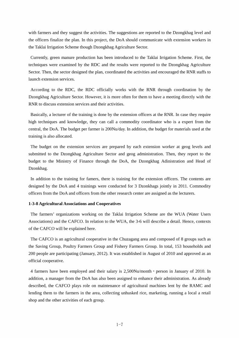
1-3-8 Agricultural Associations and Cooperatives
The farmers’ organizations working on the Taklai Irrigation Scheme are the WUA (Water Users
Associations) and the CAFCO. In relation to the WUA, the 3-6 will describe a detail. Hence, contexts
of the CAFCO will be explained here.
The CAFCO is an agricultural cooperative in the Chuzagang area and composed of 8 groups such as
the Saving Group, Poultry Farmers Group and Fishery Farmers Group. In total, 153 households and
200 people are participating (January, 2012). It was established in August of 2010 and approved as an
official cooperative.
4 farmers have been employed and their salary is 2,500Nu/month・person in January of 2010. In
addition, a manager from the DoA has also been assigned to enhance their administration. As already
described, the CAFCO plays role on maintenance of agricultural machines lent by the RAMC and
lending them to the farmers in the area, collecting unhusked rice, marketing, running a local a retail
shop and the other activities of each group.
1-7

They have made efforts to secure official markets and participate in trading show. In addition, they
are able to keep a proper record on the administration. Thus, it can expect that they play a crucial role
on proper maintenance of agricultural machine, processing increased agricultural products and
capturing more market cannels.
The famers in the Sershong area do not have agricultural cooperatives such as the CAFCO, many
famers sell crops by themselves rather than through cooperatives or groups. This may be a reason that
farm gate price of unhusked rice in the Sershong area is lower than that in the Chuzagang area.
Because people from the other geogs can also join the CAFCO, it expects that the CAFCO leads
people in the Sershong area to participate and work jointly.
1-4 Natural condition
1-4-1 Topographic, Geological and Climatic classification
Topographically Bhutan is divided into 4 zones with its geological condition, I) Greater Himalayan
zone, II) Lesser Himalayan zone, III) Sub-Himalayan zone and IV) Quaternary sediment zone. Taklai
Irrigation Area is located within IV) Quaternary sediment zone. Quaternary sediment zone consist of
alluvial fan and river terrace developing on the mountain foot along the boundary to India. Since its
altitude is 200 - 400m with mild slope, agricultural potential of this zone is high.
Climatic classification of Taklai Irrigation Area is Humid and Wet Sub-tropical zone.
1-4-2 Meteorological condition at Taklai Irrigation Area
(1) Structure of meteorology observation
There are 2 classes of observation station for meteorological condition. Items being observed at each
class of station and location of observation stations are mentioned in the table and figure below.
Table 1-3: Items being observed at meteorology observation station
Class Class A Class-C
Observed items
Daily rainfall (mm/day) Maximum Temperature ( C) Minimum Temperature ( C) Relative Humidity (%) Wind Speed (m/s) Wind Direction Sunshine (hr) Cloud Cover (oktas)
Daily rainfall (mm/day) Maximum Temperature ( C) Minimum Temperature ( C)
1-8

Fig 1-3: Location of meteorology observation stations
Since Taklai Irrigation Area has no meteorological observation stations within its catchment area, its
meteorological condition is examined using record at Bhur observation station (Class-A, altitude 375m,
location: RNR Research and Development Center) due to its similarity of natural condition as Taklai
Irrigation Area.
Meteorological condition of Bhur and Thimphu observation station (Class-A, altitude 2,380m,
location: MoEA complex) are shown in the figure below. On the following pages, record of Thimphu
observation station is also shown as reference.
Fig 1-4: Meteorological condition (average for last 10 years)
(2) Rainfall
a) Annual rainfall and Maximum daily rainfall in a year
Annual rainfall and maximum daily rainfall in a year for last 10 years are shown as following,
Monthly rainfall Maximum temperature Minimum temperature
-20
-10
0
10
20
30
40
50
0
200
400
600
800
1,000
1,200
1,400
JAN FEB MAR APR MAY JUN JUL AUG SEP OCT NOV DEC
Tem
pera
ture
(deg
ree)
Mon
thry
rain
fall
(mm
)
Thimphu: 2002-2011
Annual Rainfall 650mm
Taklai Irrigation Area Bhur
Thimphu
:Meteorological observation station(Class-A) :Dzongkhag boundary
:National boundary
-20
-10
0
10
20
30
40
50
0
200
400
600
800
1,000
1,200
1,400
JAN FEB MAR APR MAY JUN JUL AUG SEP OCT NOV DEC
Tem
pera
ture
(deg
ree)
Mon
thry
rain
fall
(mm
)
Bhur: 2002-2011
Annual Rainfall 5,120mm
1-9
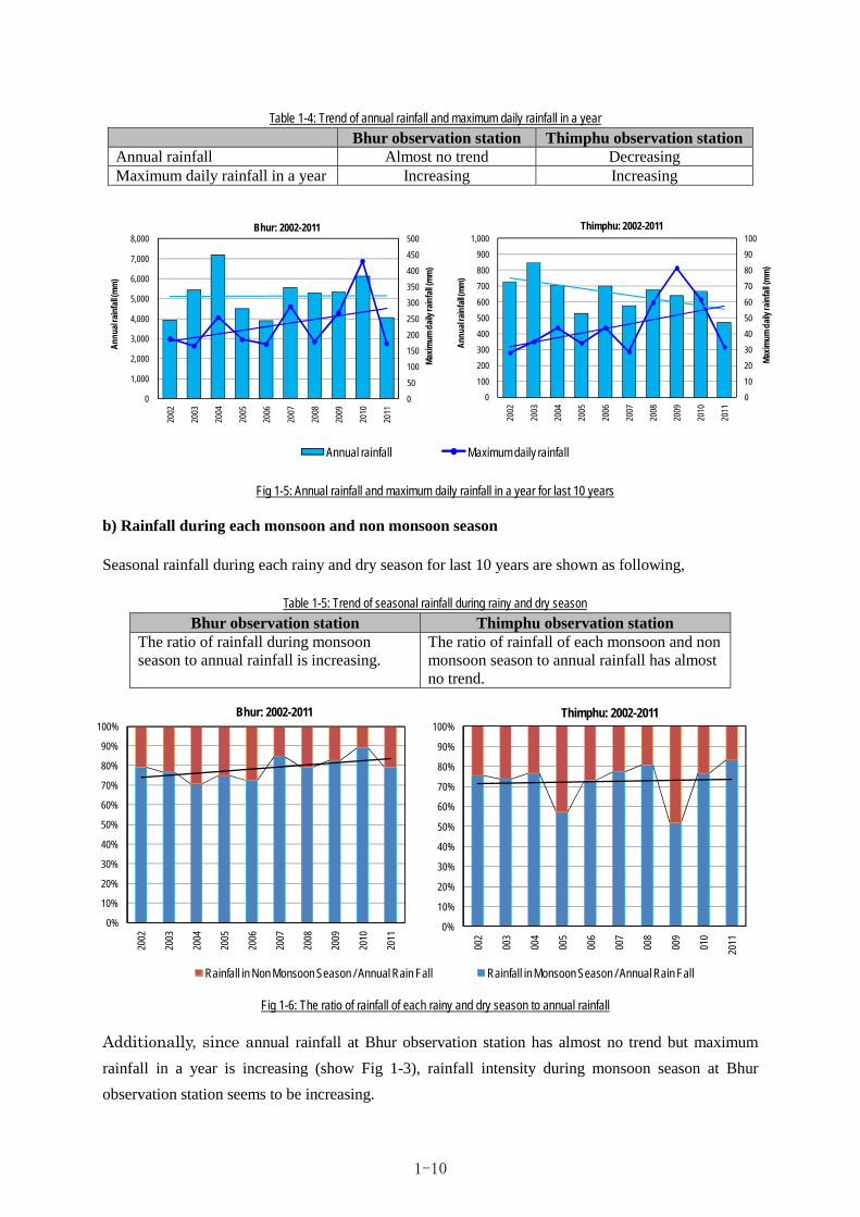
Table 1-4: Trend of annual rainfall and maximum daily rainfall in a year
Bhur observation station Thimphu observation stationAnnual rainfall Almost no trend Decreasing Maximum daily rainfall in a year Increasing Increasing
Fig 1-5: Annual rainfall and maximum daily rainfall in a year for last 10 years
b) Rainfall during each monsoon and non monsoon season
Seasonal rainfall during each rainy and dry season for last 10 years are shown as following,
Table 1-5: Trend of seasonal rainfall during rainy and dry season
Bhur observation station Thimphu observation station The ratio of rainfall during monsoon season to annual rainfall is increasing.
The ratio of rainfall of each monsoon and non monsoon season to annual rainfall has almost no trend.
Fig 1-6: The ratio of rainfall of each rainy and dry season to annual rainfall
Additionally, since annual rainfall at Bhur observation station has almost no trend but maximum
rainfall in a year is increasing (show Fig 1-3), rainfall intensity during monsoon season at Bhur
observation station seems to be increasing.
0
10
20
30
40
50
60
70
80
90
100
0
100
200
300
400
500
600
700
800
900
1,000
2002
2003
2004
2005
2006
2007
2008
2009
2010
2011
Max
imum
dai
ly ra
infa
ll(m
m)
Ann
ual r
ainf
all (
mm
)
Thimphu: 2002-2011
0
50
100
150
200
250
300
350
400
450
500
0
1,000
2,000
3,000
4,000
5,000
6,000
7,000
8,000
2002
2003
2004
2005
2006
2007
2008
2009
2010
2011
Max
imum
dai
ly ra
infa
ll(m
m)
Ann
ual r
ainf
all (
mm
)
Bhur: 2002-2011
Annual rainfall Maximum daily rainfall
0%
10%
20%
30%
40%
50%
60%
70%
80%
90%
100%
2002
2003
2004
2005
2006
2007
2008
2009
2010
2011
Bhur: 2002-2011
0%
10%
20%
30%
40%
50%
60%
70%
80%
90%
100%
2002
2003
2004
2005
2006
2007
2008
2009
2010
2011
Thimphu: 2002-2011
Rainfall in Non Monsoon Season / Annual Rain Fall Rainfall in Monsoon Season / Annual Rain Fall
1-10
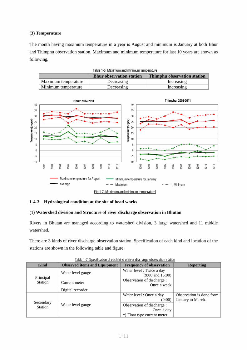
(3) Temperature
The month having maximum temperature in a year is August and minimum is January at both Bhur
and Thimphu observation station. Maximum and minimum temperature for last 10 years are shown as
following,
Table 1-6: Maximum and minimum temperature
Bhur observation station Thimphu observation stationMaximum temperature Decreasing Increasing Minimum temperature Decreasing Increasing
Fig 1-7: Maximum and minimum temperaturel
1-4-3 Hydrological condition at the site of head works
(1) Watershed division and Structure of river discharge observation in Bhutan
Rivers in Bhutan are managed according to watershed division, 3 large watershed and 11 middle
watershed.
There are 3 kinds of river discharge observation station. Specification of each kind and location of the
stations are shown in the following table and figure.
Table 1-7: Specification of each kind of river discharge observation station
Kind Observed items and Equipment Frequency of observation Reporting
Water level gauge Water level : Twice a day
(9:00 and 15:00)
Current meter Observation of discharge :
Once a week
Principal Station
Digital recorder
Water level : Once a day (9:00)
Observation of discharge : Once a day
Secondary Station
Water level gauge
*) Float type current meter
Observation is done from January to March.
-10
-5
0
5
10
15
20
25
30
35
40
2002
2003
2004
2005
2006
2007
2008
2009
2010
2011
Tem
pera
ture
(deg
ree)
Bhur: 2002-2011
-10
-5
0
5
10
15
20
25
30
35
40
2002
2003
2004
2005
2006
2007
2008
2009
2010
2011
Tem
pera
ture
(deg
ree)
Thimphu: 2002-2011
Maximum temperature for August Minimum temperature for January
Maximum Minimum Average
1-11

Kind Observed items and Equipment Frequency of observation Reporting Spot Low Flow Measurement
Current meter (Propeller type)
Observation of discharge : Once a year
Source : Surface Hydrological data of Bhutan 2009, Department of Energy
Source : Surface Hydrological data of Bhutan 2009, Department of Energy
Fig 1-8: Watershed division and location of river discharge observation station
(2) Hydraulic regime at the site of head works
a) Hydraulic regime during study period
Taklai river on which head works are planned to be constructed has no record of its discharge.
Although it is just for reference, river discharge at the head works construction point has been
measured through this study to grasp the specification of river discharge.
As results of measurement, drought water discharge measured during non monsoon season seems to be
usable data. However since amount of flood discharge measured during monsoon season is different
from that estimated by rational formula mentioned below, it seems difficult to be usable data.
b) Estimation of Flood discharge
Flood discharge at the site of head works is estimated according to the following 2 means.
i) Estimation using rainfall data at Bhur observation station
ii) Estimation using flood trace at the site
Taklai Irrigation System
: Principal Station : Secondary Station : Boundary of large watershed
1-12

As a result of estimation using rational formula, 1,710m3/s is calculated as flood discharge with
50years occurrence probability.
=1,710m3/s
Q: peak flood discharge (m3/s),
f: coefficient of discharge (=0.7),
r: average rainfall within flood reaching time (=102 mm/hr),
A: catchment area (= 86.24km2)
ii) Estimation using flood trace at the site
The 6m depth of past flood trace is observed at the site. In this case, 1,330m3/s of river discharge is
calculated as the past maximum flood discharge, according to the hearing at the site.
Fig 1-9: Maximum flood discharge and water depth in the past
c) Estimation of drought water discharge
Drought water discharge at the site of head works is estimated according to the following 2 means.
i) Measurement result of discharge at the site
ii) Estimation using discharge data at the other rivers with similar natural condition as Taklai
Irrigation system
i) Measurement result of discharge at the site
Discharge measured at the site of head works on 1st February, 2012 was approximately 3.8m3/s.
ii) Estimation using discharge data at the other rivers with similar natural condition as Taklai Irrigation
system
Rivers having similar natural condition as Taklai
Irrigation System are Mau River, Bhur River and
Sarpang River. At these rivers, minimum water
discharge is measured once a year during January to
March. Analysis results of drought water discharge of
each river are shown in the table below. Unit
discharge of each river is almost same.
Fig 1-10 Location of Mau, Bhur and Sarpang river
1-13

Table 1-8: Estimation results of drought water discharge of Mau, Bhur and Sarpang river
Drought water discharge (m3/s) (Unit discharge (m3/s/km2))
River Catchment
area (km2) 1time
/10years1time
/5years 1time /1year
Maximum in last 5years
Second maximum in last 10years
Remarks
Mau River
744.638.1644
(0.0110)8.7004
(0.0117)9.7948
(0.0132) 7.7510
(0.0104) 7.9610
(0.0107) 1992 - 2007
(Excluding 1993) Bhur River
81.000.8157
(0.0101)0.8776
(0.0108)1.0111
(0.0125) 0.8260
(0.0102) 0.8080
(0.0100) 1993 - 2008
(Excluding 2004) Sarpang
River 135.25
1.4033(0.0104)
1.5326(0.0113)
1.8140 (0.0134)
1.6930 (0.0125)
1.5940 (0.0118)
1995 - 2008
Average of unit discharge
(m3/s/km2) 0.0105 0.0113 0.0130 0.0110 0.0108
Estimated drought water discharge at the site of head works multiplying average of unit discharge
shown in the table above and catchment area at the site is shown in the table below. As a result,
1.1211m3/s is calculated as drought water discharge with 1year occurrence probability.
Table 1-9: Estimation results of drought water discharge at the site of head works
Drought water discharge (m3/s) (Unit discharge (m3/s/km2))
River
CatchmentArea at the
site (km2)
1time /10years
1time /5years
1time /1year
Maximum in last 5years
Second maximum in last 10years
Remarks
Taklai River
86.24 0.9055 0.9745 1.1211 0.9486 0.9314
1-4-4 Effects of earthquake
Generally, civil structure constructed under the ground or having no protrusion does not suffer damage
from earthquake. Although Bhutan has suffered damage from earthquake due to its location on the
border between Eurasia and Indian plate, since Taklai Irrigation System has no protrusion, seismic
force is not considered for design.
1-4-5 Geological survey
The geological survey conduct to study the feature at candidate site for headworks. The contents of
survey is shown as follows;
① Boring (Including the sounding) : 2 boring, right and left bank x depth 10 meter around
Candidate site of headworks, and 2 boring on center of river
x depth 5 meter around Candidate site of headworks
② Standard penetration test (SPT) : Each 1 meter depth, totally 26 nos.
③ Sampling for Laboratory test : 10 nos.
④ Result
1-14

Geological formation in and around the planned site of head works can roughly be classified into
gravel and pebbles over the stream-bed and quartzite / gneissic boulder derived from volcanic origin
materials judging from the result of a geologic survey. Both of these strata are relatively compact
judging from the measurement results with 35° or larger for their internal friction angle and about
2.0tf/m3 as unit weight.
1-4-6 Topographic survey
The topographic survey conduct to study the basic condition. The contents of survey is shown as
follows;
① Candidate site of headworks : Check the bench mark and longitudinal and cross section survey
② Main canal (High and Low) : Check the bench mark and longitudinal and cross section survey
③ Link canal : Check the bench mark and longitudinal and cross section survey
④ Related structure on the main canals : Inventory survey and make drawing
⑤ Candidate site of protection dike : Check the bench mark and longitudinal and cross section survey
1-5 Environmental and Social Consideration
1-5-1 Preparation and submission of Initial Environmental Examination (IEE) Report
As this Project include new construction of weir and rehabilitation of the existing canal, it is subject
to the application of Initial Environmental Examination (IEE) in compliance with “Processing
Environmental Clearance for Irrigation Construction Projects: A Guide for Proponents (October
2004)”. It follows that application for environmental report on IEE has to be submitted to NEC. NEC
issues the environmental permit provided that the contents of the report of IEE satisfy the conditions
for environment conservation.
1-5-2 Procedure for securing environmental approval
NEC confirmed that the subject project is a development project and IEE report must be submitted to
the Authorities concerned. Accordingly, DoA prepared the IEE report on the schemes with having
due assistance by the JICA survey team and submitted the IEE report to the NEC on August 28, 2012.
The IEE report was carefully considered by NEC and it was on 2nd November 2012 that the
Environmental Approval was duly issued. (Ref. Appendix- 6.10).
1-5-3 Environmental Impact Assessment
(1) Outline of the Component of Environmental Impact
The project is categorized as agricultural project and the components as follows;
1-15

Table 1-10:Outline of the project components
Item of facility Description
1. Integrated Headwork ・Fixed Weir:L 38.9m x 1.0m ・Bed protection:L= 30.0 m
2. Head race and sedimentation basin
・Box culvert:L= 358.9m ・Open canal:L= 631.2m ・Sedimentation Basin:L= 37.5m ・Retaining wall:H 3.9m x L 410m
3. Link canal ・Rise up wall:L= 654.6m ・Improvement:L= 109.6m
4. Confluence between Link canal and Low level intake
・L type retaining wall H 2m x L 4.65m ・Newly constructing gate:One (1) gate
5. High Level canal
・Wet masonry:L= 123.7m ・Rise up wall:L=165m ・Covered by concrete:L= 205.8m ・Rehabilitation of leakage at 2nd siphon outlet:Covered by concrete・Rehabilitation of leakage at aqueduct:L=50m ・Safe fence around siphon:6 nos. ・Improvement of siphon:covered by reinforce concrete ・Concrete bridge:re-construction (width 4m) x 2 bridges
6. Exposed siphon pipe on High Level Canal ・Protection of exposed siphon pipe at 3rd siphon L= 45m
7. Gate on High and Low Level Canal ・High Level Canal : Check and distribution gate:10gates ・Low Level Canal : Check gate:2gates
8. Water gauge at integrated headwork ・Water gauge:Sound wave type 1 set
9. Protection dike at downstream of Taklai River
・Dike:W 4.0m x H3.0m x L 340m ・Retaining wall:H 3.9m x L 340m
10. Soft component ・ Instruction and assistance for operation of facility, water management, maintenance
In this project does not assume the great impact or damage to environment considering above project
component. However, there are possibly negative impact in a part of area, therefore this project is
categorized into " Category B" based on " JICA Guidelines for Environmental and Social
considerations (the new Guidelines, April 2010)"
Fig 1-11 : Project site
1-16

(2) Condition of Basic Environment and Society
Bhutan has 10 national parks and project site is at close Royal Manas national park of west side. This
area is 2,873 km2 which divided between Buffer Zone : 2,446km and Core Area : 391km2. In addition,
those are observed humid and grass covered area, semi-Himalaya humid and deciduous forest,
semi-Himalaya alpine humid and evergreen forest and lowland humid savannah. Furthermore, there
are almost 20 animals which are in danger of extinction, therefore these area is important for the
species preservation.
In site survey, the team made sure that location of national park is the left bank of Taklai river and
project site is outside of these national protected area. Finally, the project scarcely give an
environmental influence to that park.
Fig 1-12 : Location between project site, and national protected area and Biological corridors of Bhutan
(3) Procedure of environmental and social considerations
The regulation of the environmental in Bhutan comply with "① Environmental Assessment Act 2000",
"② Regulation for the Environmental Clearance of Project (2002), "③National Environment
Protection Act of Bhutan, 2007.
A flow chart of procedure for the environmental assessment is shown on Fig 1-13. According to the
flow chart, National Environmental Committee (NEC) assess the monitoring and evaluation for the
designed irrigation plan based on above latest lows. After the assessed by NEC, NEC will issue the
environmental approval, then DoA which is executive agency in this project, will start the project
Project site
1-17

follow the environmental regulation by NEC.
An application for the environmental and social considerations in Bhutan is of the Processing
Environmental Clearance for Irrigation Construction Projects : A Guide for Proponents (October 2004).
According to that guideline, in case of new construction or large improvement of the irrigation system,
environmental approval should be needed before commencement of construction.
The application submitted by executive agency should be contained the expectation and assessment for the
environmental influence, in addition the measurement as the alleviation or remove for influence should be
described on that application as well as monitoring plan during the construction period in order to confirm
the monitoring performance. Under the condition of filled with above mentioned, NEC will issue the
environmental approval.
DoA, executive agency, will monitor the monitoring performance through the site check in project period.
(4) Alternative Plans
As an examination of alternative activities that can be replaced with this Project, the following three
alternatives are examined by comparison, namely alternative A: the existing state of irrigation
(zero-option), alternative B: cooperation project by JICA (on rehabilitation basis) and alternative C:
new land reclamation (such as new farming settlement). As shown in the following table, it has been
concluded that the alternative B (this Project) is the most feasible among these three.
Dur
atio
n 3
-4
mo
nth
s
Du
ratio
n 1
mo
nth
s
Fig 1-13 : Procedure of Environmental and Social Considerations
1-18

Table 1-11: Examination of replaceable alternatives
Type Content Technical/ financial difficulty
Land use Environmental impact Social impact
Evalu-ation
PLAN-A Existing project (zero- option)
◎The same as it is now
◎The same as it is now
◎The same as it is now
×Since continuous intake is impossible, food production cannot be increased. Repair is necessary every time after floods.
×
PLAN-B The Project by JICA
Techniques to be applied has already been established. Since this Project consists of installation of small scaled weir and rehabilitation of the existing canal, the incurred cost is cheaper than that of the whole new construction
◎Almost the same as it is now, because the project consists of only the installation of a weir and rehabilitation of the canal
Almost the same as it is now
◎The Project enables to secure stable supply of irrigation water distribution, thus increased food production can be expected. Also, employment opportunities are generated from the construction work.
◎
PLAN-C Newly reclaimed development project
×This requires new study, design and construction work to realize.
△Requiring development of new perimeter
△From the necessity of new land reclamation, need of newly evaluating impact to local environment arises.
◎ The same as above column
△
Classification of Evaluation × : No Good △ : Fine ◎ : Very Good
(5) Scooping
The following table gives scoping on impact of the major components included in this Project to
environment and society. This Project does not give any serious impact to the environment and society.
Table 1-12: Scoping (Before environmental and social conditions survey)
Evaluation No Environment Item Under
construction During the
use Reason of judgment
Countermeasures against pollution
1 Air pollution B- D Under construction: On rehabilitation work with heavy machinery, trucks are supposed, but no serious degree of air pollution takes place. However, dust is generated when vehicles pass. During the use: Once offering for use, no impact of air pollution arises.
2 Water pollution B- D Under construction: Accompanying with newly constructing work of the weir, turbid water may occur in the river. During the use: Once offering for use, no impact of water pollution arises。
3 Wastes B- D Under construction: Wastes and scraps (mostly excavated earth) are more or less resulted from excavation and other construction work. During the use: Once offering for use, no waste is generated
4 Soil pollution D D Since this Project has the objective of irrigation water supply, no soil pollution is resulted from the work.
5 Noise / vibration
B- D Under construction: Transport of materials by heavy machinery and trucks are made toward the sites. However, serious noise / vibration is
1-19
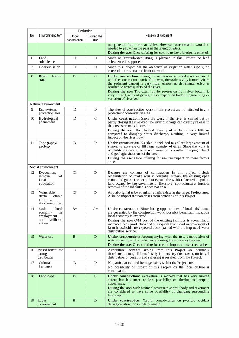
Evaluation No Environment Item Under
construction During the
use Reason of judgment
not generate from these activities. However, consideration would be needed to pay when the pass in the living quarters. During the use: Once offering for use, no noise/ vibration is emitted.
6 Land subsidence
D D Since no groundwater lifting is planned in this Project, no land subsidence is supposed.
7 Odor emission D D Since this Project has the objective of irrigation water supply, no cause of odor is resulted from the work.
8 River bottom state
B- C Under construction: Though excavation in river-bed is accompanied with the construction work of the weir, the scale is very limited where the sediment deposit is very little. Almost no detrimental effect is resulted to water quality of the river. During the use: The extent of the protrusion from river bottom is very limited, without giving heavy impact on bottom regimenting or variation of river bed.
Natural environment
9 Eco-system, protection area
D D The sites of construction work in this project are not situated in any protection/ conservation area.
10 Hydrological phenomena
D C Under construction: Since the work in the river is carried out by partly closing the river-bed, the river discharge can directly release to the downstream as before. During the use: The planned quantity of intake is fairly little as compared to droughty water discharge, resulting in very limited impact on the river flow.
11 Topography/ geology
D D Under construction: No plan is included to collect large amount of stones, to excavate or fill large quantity of earth. Since the work is rehabilitating nature, no sizable variation is resulted in topographical and geologic situations of the area. During the use: Once offering for use, no impact on these factors arises
Social environment
12 Evacuation, removal of local population
D D Because the contents of construction in this project include rehabilitation of intake weir in torrential stream, the existing open canals and gates. The section to expand the width is located on public land owned by the government. Therefore, non-voluntary/ forcible removal of the inhabitants does not arise.
13 Vulnerable strata, ethnic minority, aboriginal tribe
D D Any aboriginal tribe or minor ethnic exists in the target Project area. Also, no impact thereon arises from activities of this Project.
14 Such local economy as employment and livelihood means
B+ A+ Under construction: Since hiring opportunities of local inhabitants are generated by the construction work, possibly beneficial impact on local economy is expected. During the use: O/M cost of the existing facilities is economized, increased crop production and subsequent livelihood improvement of farm households are expected accompanied with the improved water distribution service.
15 Water use B- D Under construction: Accompanying with the new construction of weir, some impact by turbid water during the work may happen. During the use: Once offering for use, no impact on water use arises
16
Biased benefit and damage distribution
D D Agricultural benefits arising from this Project are equitably distributed among all beneficially farmers. By this reason, no biased distribution of benefits and suffering is resulted from the Project.
17
Cultural heritages
D D No particular cultural heritage exists within the Project area. No possibility of impact of this Project on the local culture is conceivable.
18
Landscape B- C Under construction: excavation is worked that has very limited extent but has more or less possibility of altering topographic appearance. During the use: Such artificial structures as weir body and revetment are considered to have some possibility of changing surrounding landscape.
19
Labor environment
B- D Under construction: Careful consideration on possible accident during construction is indispensable.
1-20

Evaluation No Environment Item Under
construction During the
use Reason of judgment
(including labor safety)
During the use: Since facilities are rehabilitated, gate operation is made easier resulting in improved labor condition.
Others
20 Accident B- D Under construction: Potential risk would arise from the Project such as possibility of traffic accidents caused by vehicles of the construction work giving damages to local inhabitants, those caused by heavy machinery during rehabilitation of open canals and gates etc. During the use: No impact on the ambient environment because of mere rehabilitation of the existing canals.
21
Territory transversal impact and risk of climatic variation
D D Taklai River over which the weir is installed is a tributary of Mao River flowing down to India, but no fluvial agreement has been concluded. Either, sizable change in the flow that can induce climatic variation is not evolved from this construction work.
Evaluation classes: A+ : Particularly positive impact is brought by the activity, A- : Particularly negative impact is brought by the activity, B+ : Positive impact is brought by the activity, B- : Negative impact is brought by the activity, C : The extent of the impact is unknown and D : No impact arises from the activity
(6) TOR of the survey for environmental and social considerations
As the result of scooping, the items evaluated "B-" as an integrated evaluation which are 1. Air
pollution, 2. Water pollution, 3. Wastes, 5. Noise / vibration, 8. River bottom state, 15. Water use, 18.
Landscape, 19. Labor environment, 20. Accident, is mentioned as follows. No. 2. Water pollution and
No.18. Landscape, however, are not occurred a substantial impact to the project, therefore these items
exclude from the Term of reference (TOR).
As the TOR, the assumed the way of survey and contents for environmental and social considerations
is shown as follows (Table 1-13);
Table 1-13: Assumed TOR of survey for environmental and social considerations
No. Items for environment Items for check How to check 1 Air pollution Impact during construction ・Check the fugitive dust on driving
truck or car 3 Wastes Impact during construction ・Check the disposal way of generated
waste 5 Noise / vibration, Impact during construction ・Check the components of construction,
the way, period, range, kind of construction machine, number of driving truck
・Check the residence area whether near the construction site is and carry out the hearing.
8 River bottom state Impact during construction ・ Check drainage condition on excavating the river
15 Water use Impact during construction ・ Check drainage condition on excavating the river
19 Labor environment Accident during construction ・Check the components of construction, the way, period, range, kind of construction machine, number of driving truck
・Conduct site survey and hearing 20 Accident Impact and accident during
construction ・Check the components of construction,
the way, period, range, kind of construction machine, number of
1-21

No. Items for environment Items for check How to check driving truck
・ Conduct site survey (traffic )and hearing
(7) Result of the survey for environmental and social considerations (include the expectation)
The result of the survey for environmental and social considerations include the expectation based on
scooping, are shown as follows;
Table 1-14: Result of survey for environmental and social considerations
No. Items for environment Measurement 1 Air pollution ・the fugitive dust generate on driving truck or car 3 Wastes ・Excavated soil and construction waste are generated, but almost excavated soil. 5 Noise / vibration, ・Transportation of the materials and so on by truck is carried out, the noise,
however, is not serious. Need to pay attention through near the residence area. 8 River bottom state ・Excavated soil is generated, however, it is not large. The bed excavation work for
the headwork is carried out, however, the muddy water is not almost occurred and given the impact.
15 Water use ・It is conceivable that muddy water is occurred during construction of headwork 19 Labor environment ・Pay attention for the accident during construction 20 Accident ・Traffic accident between residence and truck of construction works is possibly
occurred when rehabilitation works for canal and gate is carried out.
(8) Assessment of environmental and social considerations
Some impact is inevitable although, the serious impact for environment is avoidable by the proper
measurement.
Table 1-15: Scoping (After environmental and social conditions survey)
Evaluation at Scooping
Evaluation after the survey
No Environment Item Under constructio
n
During the use
Under constructi
on
During the use
Reason of judgment
Countermeasures against pollution
1 Air pollution B- D B- N/A Under construction: On rehabilitation work with heavy machinery, trucks are supposed, but no serious degree of air pollution takes place. However, dust is generated when vehicles pass. During the use: Once offering for use, no impact of air pollution arises.
2 Water pollution B- D B- N/A Under construction: Accompanying with newly constructing work of the weir, turbid water may occur in the river. During the use: Once offering for use, no impact of water pollution arises。
3 Wastes B- D B- N/A Under construction: Wastes and scraps (mostly excavated earth) are more or less resulted from excavation and other construction work. During the use: Once offering for use, no waste is generated
4 Soil pollution D D N/A N/A Since this Project has the objective of irrigation water supply, no soil pollution is resulted from the work.
5 Noise / vibration
B- D B- N/A Under construction: Transport of materials by heavy machinery and trucks are made toward the sites. However, serious noise / vibration is not generate from these activities. However, consideration would be needed to pay when the pass in the living quarters.
1-22
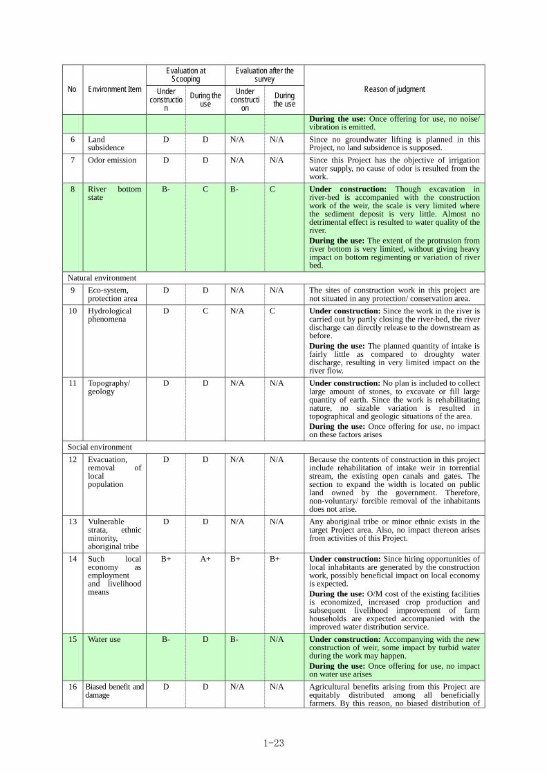
Evaluation at Scooping
Evaluation after the survey
No Environment Item Under constructio
n
During the use
Under constructi
on
During the use
Reason of judgment
During the use: Once offering for use, no noise/ vibration is emitted.
6 Land subsidence
D D N/A N/A Since no groundwater lifting is planned in this Project, no land subsidence is supposed.
7 Odor emission D D N/A N/A Since this Project has the objective of irrigation water supply, no cause of odor is resulted from the work.
8 River bottom state
B- C B- C Under construction: Though excavation in river-bed is accompanied with the construction work of the weir, the scale is very limited where the sediment deposit is very little. Almost no detrimental effect is resulted to water quality of the river. During the use: The extent of the protrusion from river bottom is very limited, without giving heavy impact on bottom regimenting or variation of river bed.
Natural environment
9 Eco-system, protection area
D D N/A N/A The sites of construction work in this project are not situated in any protection/ conservation area.
10 Hydrological phenomena
D C N/A C Under construction: Since the work in the river is carried out by partly closing the river-bed, the river discharge can directly release to the downstream as before. During the use: The planned quantity of intake is fairly little as compared to droughty water discharge, resulting in very limited impact on the river flow.
11 Topography/ geology
D D N/A N/A Under construction: No plan is included to collect large amount of stones, to excavate or fill large quantity of earth. Since the work is rehabilitating nature, no sizable variation is resulted in topographical and geologic situations of the area. During the use: Once offering for use, no impact on these factors arises
Social environment
12 Evacuation, removal of local population
D D N/A N/A Because the contents of construction in this project include rehabilitation of intake weir in torrential stream, the existing open canals and gates. The section to expand the width is located on public land owned by the government. Therefore, non-voluntary/ forcible removal of the inhabitants does not arise.
13 Vulnerable strata, ethnic minority, aboriginal tribe
D D N/A N/A Any aboriginal tribe or minor ethnic exists in the target Project area. Also, no impact thereon arises from activities of this Project.
14 Such local economy as employment and livelihood means
B+ A+ B+ B+ Under construction: Since hiring opportunities of local inhabitants are generated by the construction work, possibly beneficial impact on local economy is expected. During the use: O/M cost of the existing facilities is economized, increased crop production and subsequent livelihood improvement of farm households are expected accompanied with the improved water distribution service.
15 Water use B- D B- N/A Under construction: Accompanying with the new construction of weir, some impact by turbid water during the work may happen. During the use: Once offering for use, no impact on water use arises
16
Biased benefit and damage
D D N/A N/A Agricultural benefits arising from this Project are equitably distributed among all beneficially farmers. By this reason, no biased distribution of
1-23

Evaluation at Scooping
Evaluation after the survey
No Environment Item Under constructio
n
During the use
Under constructi
on
During the use
Reason of judgment
distribution benefits and suffering is resulted from the Project.
17
Cultural heritages
D D N/A N/A No particular cultural heritage exists within the Project area. No possibility of impact of this Project on the local culture is conceivable.
18
Landscape B- C B- C Under construction: excavation is worked that has very limited extent but has more or less possibility of altering topographic appearance. During the use: Such artificial structures as weir body and revetment are considered to have some possibility of changing surrounding landscape.
19
Labor environment (including labor safety)
B- D B- N/A Under construction: Careful consideration on possible accident during construction is indispensable. During the use: Since facilities are rehabilitated, gate operation is made easier resulting in improved labor condition.
Others
20 Accident B- D B- N/A Under construction: Potential risk would arise from the Project such as possibility of traffic accidents caused by vehicles of the construction work giving damages to local inhabitants, those caused by heavy machinery during rehabilitation of open canals and gates etc. During the use: No impact on the ambient environment because of mere rehabilitation of the existing canals.
21
Territory transversal impact and risk of climatic variation
D D N/A N/A Taklai River over which the weir is installed is a tributary of Mao River flowing down to India, but no fluvial agreement has been concluded. Either, sizable change in the flow that can induce climatic variation is not evolved from this construction work.
Evaluation classes: A+ : Particularly positive impact is brought by the activity, A- : Particularly negative impact is brought by the activity, B+ : Positive impact is brought by the activity, B- : Negative impact is brought by the activity, C : The extent of the impact is unknown and D : No impact arises from the activity
1-5-4 Elaboration of impact-mitigating measures
As possible measures to alleviate and to avoid negative impacts likely to take place by the
implementation of this Project, the following countermeasures are considered necessary as tabulated
below. These impact alleviating or avoiding measures can be realized to put into practice within the
indirect cost included in the contract between Japanese government and constructors, thus no
additional cost is required for taking them. As concern monitoring, the contracted constructor monitors
the ambient environment impacts in compliance with the laws and regulations of Bhutan, then the
consultant engaged in this Project identifies the contents of the constructor’s report, the consultant
submits the report to Bhutan side, and then need to receive the approval by Bhutan side.
Almost no detrimental effect is resulted to Air pollution and Water pollution, and then those are not
included in the Monitoring plan.
1-24

Table 1-16: Elaboration of negative impact alleviating measures
Negative impact Alleviating or avoiding measures
Monitoring plan Responsible Agency
【Air pollution】 Dust occurs during the passage of construction vehicles.
・ Water will be sprinkled on the road during construction works.
【Method】Whether proper / legal treatment or disposal is practiced or not is identified at the sites. 【 Period 】: Construction period 【Frequency】:once / month
Contractor DoA
【Wastes】 Excavated earth evolves from some construction work. In rehabilitating the existing canals, waste scrap pieces evolves.
・ As to the method of disposal of wastes, the standard of waste disposal/ treatment practiced in Bhutan is observed.
【Method】Whether proper / legal treatment or disposal is practiced or not is identified at the sites. 【 Period 】: Construction period 【Frequency】:once / month
Contractor DoA
【Noise/ vibration】 During construction work, Noise/ vibration evolve from operation of back-hoes and passage of trucks.
・ Construction machinery mounted with silencers and adequate mufflers are used to minimize noise emission.
・ In the sections where residence quarter is located, construction work at night is refrained.
【 Method 】 State of heavy machinery use is identified at the construction sites. ・ Hearing is held amidst
neighbors to Identify whether complaints are made. 【 Period 】: Construction period 【Frequency】:once / month
Contractor DoA
【 Hydrological phenomena】【water use】 Turbid water evolves during the excavation at river-bed.
・ Since the work in the river is carried out by partly closing the river-bed, the evolved turbid water can be treated in a sedimentation basin installed at downstream of the evolving sites.
【Method】Whether proper treatment is practiced or not is identified at the sites. 【 Period 】: Construction period 【Frequency】:once / month
Contractor DoA
【 Labor environment 】【Accident】 During construction work, traffic or site-work accidents may be caused.
・ Whether there is too tight operation schedule or not is identified.
・ Traffic control staff is placed along the construction roads.
・ The constructor explains contents of the work to the workers with necessary care taking for their safety to the laborers prior to the start of the work, and makes daily safety identification before the work.
【Method】Content, method, duration, area/ extent of the work, kind of mobilized construction machinery / vehicles are carefully identified. ・ Site traffic frequency
survey and hearing are conducted to ensure safety.
【 Period 】: Construction period 【Frequency】:once / month
Contractor DoA
1-5-5 Monitoring Plan and Environmental Checklist
The provision of monitoring plan and environment check list has been elaborated in DoA of ministry
of agriculture and forestry under the support by the staff of the Study Team in charge of environment
consideration. This item is included in the identification of the state of construction work, and
performed by the budget estimated as an item of indirect instruction cost. Environment monitoring is
to be made by the contracted constructor. Contractor should report to consultant, then consultant
should report to DoA at the periodical site check by DoA or meeting. The monitoring is conducted
monthly, while the report to JICA is carried out quarterly based on Minutes of Discussion on
Attachment-4.2 with the acceptance of reported by DoA. The way of information disclosure is
recommended to use the web site of Bhutan desirably in order to open the information widely
1-25

1-5-6 Stakeholder’s Meeting
Necessity of environmental and social consideration for the present project is explained to
stakeholders including Geog and WUC.
1-5-7 Land acquisition and resettlement
Necessity of land acquisition and resettlement in the project is not required. In Bhutan, generally, in
case of requirement of land acquisition which is more than 5 acre per household, the government of
Bhutan pay the compensation for the land owner with alternate land. In case of the less 5 acre per
household, the government correspondingly pay the compensation
1-5-7-1 Necessity of land acquisition and resettlement
This matter nothing to do with project
1-5-7-2 Legal framework for land acquisition and resettlement
This matter nothing to do with project
1-5-7-3 The range of area for land acquisition and resettlement
This matter nothing to do with project
1-5-7-4 The detailed measurement for compensation and support
This matter nothing to do with project
1-5-7-5 The way of complaint management
This matter nothing to do with project
1-5-7-6 Implementation agency for the resettlement and responsibility
This matter nothing to do with project
1-5-7-7 Implementation schedule
This matter nothing to do with project
1-5-7-8 Finance and budget
This matter nothing to do with project
1-5-7-9 Monitoring and monitoring form by executive agency
This matter nothing to do with project
1-5-7-10 Meeting of residence
This matter nothing to do with project
1-5-8 Draft monitoring form
Attached on appendix-A6.8
1-5-9 Check list of environment
Attached on appendix-A6-8.
1-26

Chapter 2 Contents of the Project
CHAPTER 2 CONTENTS OF THE PROJECT
2-1 Basic concept of the project
National Development Tenth Five-Year Plan (2008-2013) is a guiding plan of Bhutan related to this Project. From agricultural point of view, Ministry of Agriculture and Forests (MoAF) has provided strategic programs for strengthening markets, marketing and production of agricultural products for the purpose of ensuring food security and alleviating rural poverty. Concretely, 29 programs have been implemented through the initiative and in charge of MoAF, by which the following impacts are expected in terms of agriculture:
① Improving self-sufficiency ratio of rice from 50% to 59%,
② Increasing the level of annual farm-income from Nu10,700 to Nu35,000 and
③ Reducing the rate of local population stratum below poverty line from 30.9% to 20%.
Out of the above-described 29 programs, 7 projects have been proposed to improve environment and efficiency of water use/intake for irrigation water targeted in southern area of Bhutan, thereby expansion of dry-season irrigation has been expected. Taklai Irrigation Area is included in one of the target areas of these programs. “Contribution to the realization of double-cropping of rice in the target beneficiary area” is considered as the overall goal of this Project.
Also, as regards the Project purpose, it aims at “enabling to supply irrigation water to the initially targeted area planned in Taklai Irrigation System”. This system has the largest beneficiary area in irrigation projects in Bhutan (over 1,000 ha) and the only one nationally-managed project. This Project is expected to serve as a model scheme in Bhutan because synergetic effect can be realized between this Project and nationally implemented canal rehabilitation scheme by the reason that rehabilitation of existing canals has been implemented as a national strategy with the objective of expanding the scale of dry-season irrigation, thus enabling stable water supply throughout the year, thereby targeting to mitigate poverty rate and to promote higher farm income, also by the reason that larger scale of project output can be anticipated by its large impact since it has larger project area than the scale of perimeter in other district (about 200ha).
In order to fulfill the above-mentioned overall goal and the project purpose, it is indispensable to realize stable water intake and water supply with permanently functioning facilities in which climatic change (abnormal scale of flood etc) are taken into consideration in its design, and it is also essential to combine new-construction and rehabilitation of irrigation facilities by hard component with the capacity improvement of maintaining and managing them by soft component. The inputs, activities and outputs of this Project contain the following:
Required Inputs
1) Procurement of machinery/equipment and materials necessary for new-construction and rehabilitation of the facilities, implementation of the work,
2) Dispatching human resources (engineers) accompanied with the above-cited activities, and
3) Dispatching Japanese engineers to provide soft component.
Required Activities
1) Conducting study for detailed design required for the above-cited procurement and work,
2) Implementation of the soft component with regard to capacity improvement for operating and
2-1

maintaining facilities.
Expected Outputs
1) Recovery of facility functions of Taklai Irrigation System as it has initially been planned,
2) Economization of operation and maintenance costs through the realization of proper water distribution by means of improved water management and optimization of operation and maintenance for the facilities.
2-2 Outline design of the requested Japanese assistance
2-2-1 Design policy
2-2-1-1 Basic policy
In formulating the Project, the position, the effects, technical and economic feasibility/ relevance of Japanese Grant Aid toward the implementation of this Project are to be verified, thereby essential and optimum design of the planned facilities is provided for obtaining proper fruit/ outputs of the Project.
Basic principles applied to the facility design include integrating the existing water-intake system of diverting water at two intakes at upstream (High Level Canal : H.L.C) and downstream (Low Level Canal : L.L.C) sites into an integrated head works (see the figure at lower right side), satisfying the capacity of the facility to convey planned water quantity by this integration, also repairing/ rehabilitating facilities of the existing irrigation system the irrigation functions of which have been damaged and deteriorated/ dilapidated.
In particular, the following three reasons are pointed out as the background of need of designing an integrated head works: 1. Since the existing two water-intakes follow gravitational intake with the intake facilities and the head race directly contacted with the stream flow that have frequently been damaged by floods, 2. expenditures at the scale of an annual average of 2.5MNu equivalent have continuously been incurred for the last 6 years only for repairing and maintaining the banks along the head race (especially heavy damages were brought in 2004 and 2010), 3. The degree of damages occurred at the banks of head race often reaches blockage of water flow that inhibits stable water intake, thus the elimination if these obstacles can be longed by the construction of the integrated head works.
The details of the design will be given below, but they are briefed here, to provide the structure of the integrated head works with sufficient strength that will be constructed at the upstream of the existing H.L.C intake with stabilized river-bed and that allows to take the totaled water quantity of both existing H.L.C and L.L.C sites. Irrigation water thus taken into the canal will be distributed at its existing downstream diversion points according to the water requirement for each irrigation area. The stable supply of irrigation water is pursued by estimating irrigation water requirement and flood discharges to be planned in the Project and strengthening a part of head race by newly constructing
Fig 2-1: Image of integrated intake
New
Headr
ace ca
nal
and
reha
bilita
tion of
exist
ingca
nal
2-2

culvert structure with reinforced concrete that will be connected to the existing main canal at H.L.C site. At the same time, with a view to functional recovery of the irrigation system in this Project, the following are to be included in the work of the Project based on the contents of the request by the Royal Government of Bhutan and on the result of the study.
Table 2-1: Target component(Comparison between Report and Request letter) Expression by Report Expression by request letter(Refer
to :Attachment/Annex-3) ① Construction of integrated head works 1) Construction of a permanent headwork at High
Level canal Intake ② Rehabilitation of head race and construction of sedimentation pond,
2) Construction of flood protection structures near the High Level and 5) Construction of a sedimentation tank / desilting chamber at High Level Canal
③ Raised up of link canal and rehabilitation of its terminal part
3) Expansion of High Level canal and Link Canal between High Level and Low Level Canal
④ Construction of flood control work at the confluence work to merge the link canal into L.L.C
4) Construction of protection structures near the confluence of Low Level Canal and link Canal
⑤ Raised up of the H.L.C and repairing its damaged part 3) Expansion of High Level canal and Link Canal between High Level and Low Level Canal
⑥ Rehabilitation of siphon in the H.L.C part of the main canal (implementing protection work for exposed part of siphon pipe and repairing damaged part)
6) Rehabilitation of siphons along main canals
⑦ Renewal of the damaged or deteriorated gates installed on the H.L.C and L.L.C
7) Rehabilitation of old gates along main canals
⑧ Installation of water gauge facility at the integrated head works,
8) Installation of river gauging station at High Level head works for flow measurement
⑨ Construction of protection dike at downstream of Taklai River for the purpose of protecting farmland and canals during floods, and
5. Protection works for farm land in the irrigation area against floods
⑩ Implementation of soft component on water management and operation/ maintenance for the facilities
5. Soft component on operation and maintenance of the new irrigation system
The figure below shows the site of the above-mentioned construction works.
Fig 2-2: Location map of the cooperation Project
2-3

2-2-1-2 Policies applied to natural/ environmental conditions
The following principles are applied to natural and environmental conditions necessary for formulating the facility construction plan.
(1) Flood discharge
1,710m3/s is adopted as the design discharge that has been calculated from 1/50 year’s probable rainfall which based on the record at Bhur Observatory Station. In this regard, this value is larger than the maximum recorded flood discharge in the past estimated from the observed flood vestiges.
(2) Drought discharge
Annually probable discharge at the site of the planned head works is estimated at around 1.12m3/s from the observation result available in and around the site. Since this value is evidently lower than design irrigation water requirement, 2.24m3/s as shown below, it is considered possible that in the course of probability evaluation drought discharge corresponded to 50% of the design water requirement appear every year.
Yet, a discharge of about 3.8m3/s has been observed at the planned site of the head works during the study team was in February, or during dry season, and the interviewed persons in this study told that such a level of discharge as observed during the study was seen every year in the interview survey.
Considering these situations, each facility is designed based on 2.24m3/s, required irrigation water quantity, however, taking account of some possibility of evolving water-deficit years failing to satisfy the planned water supply, such practices as rotational irrigation and time-limited irrigation covering all blocks in a day is planned to cope with such possibility.
(3) Geology at the planned site of head works
Geological formation in and around the planned site of head works can roughly be classified into gravel and pebbles over the stream-bed and quartzite / gneissic boulder derived from volcanic origin materials judging from the result of a geologic survey. Both of these strata are relatively compact judging from the measurement results with 35° or larger for their internal friction angle and about 2.0tf/m3 as unit weight.
The Strata at planned site is composed of gravel and pebbles mainly. therefore it is difficult to execute the SPT (Standard Penetration Test) to understand the durability of foundation such as by the N value. However there is no settlement strata to be predicted, because the such as clay stratum could not find by boring survey. On the other hand, the internal friction is identified as 35 degree at stratum around below EL 298 which is understood as tight gravel and pebbles stratum. Accordingly, the structure foundation level is deeper than EL 298.
Therefore, it is considered feasible to adopt this site as the foundation of the planned head works by subject to be removed the mobile river-bed gravel. And an apron of head works is designed as floating type because the foundation is conceived high permeable strata. The following table gives parameters of basement clarified by the geological survey.
2-4

2-2-1-3 Farming and irrigational (on-farm) conditions
As this Project has main objective of functional recovery for Taklai Irrigation System through new construction of integrated head works and head race as well as rehabilitation of main canal and appurtenant structures etc, farming environment of the beneficial farmers will be improved as a result of enabling stable supply of irrigation water. Thus, expansion of irrigation area that leads to increasing crop production is anticipated, further this improved irrigation will enable to realize spring cropping (dry-season farming) that is rarely practiced at present. In such a way, shifting to double-cropping probably induces a transformation in cropping pattern.
As far as crop selection has basically been kept at farmer’s own disposal without any policy intervention, it is predicted that some farmers surely try to be engaged in spring crops (dry-season cropping) with paddy and wheat once stable supply of irrigation water is realized. Research and Development Center (RDC) takes charge of research and development including formulation of year-round farming plan in conjugation with the alteration in cropping pattern, selection of paddy varieties, cropping technology and post-harvest practices while Dzongkhag Agriculture Sector (DAS) are responsible for extension activities, thus supporting beneficiary farmers.
No radical change is brought in the operation and maintenance of terminal irrigation facilities and sharing system of water management (operation of water-gates), and RDC and Central Machinery Unit (CMU) (only on major damage) are in charge of controlling basic facilities (from head works to main canal) while Water Users Associations (WUA) takes responsibility of operating and maintaining secondary canals up to terminal facilities. As regards operation of water-gates, water guards selected and appointed by WUA are responsible for them.
2-2-1-4 Policies applied to socio-economic situations
It is considered that the rehabilitation of Taklai Irrigation System and subsequent improvement in farming conditions contribute to beneficiary farmer’s increased food production and their livelihood improvement, leading to favorable impact to local economy. Fortunately, no cases of land-use system in which only a part of farmers hold large tract of farmland obtaining biased benefits are observed in Taklai irrigation area, so it is forecast that this Project gives equal benefits to as many beneficial farm households as possible.
In so far as this Project has the objective of rehabilitating the existing Taklai Irrigation System, it won’t bring any new large-scaled development in the area. It follows that living customs and traditions of the beneficiaries will be conserved as they are now.
Further, from gender point of view, men and women used to share farm labor/ practices within household or community, hence it is considered that expansion of cropping area would not result in an
Table 2-2: Basement parameters of the basement at the planned site of the head works
Sourced by of Geological Survey Report
2-5

increased burden for women only.
2-2-1-5 Policies on the situations of construction / procurement
(1) Laws and regulations to be pursued
As to labor conditions including minimum rate of wages and labor hours, they are based on the articles described in Labor Standardization Law in Bhutan.
(2) Standard norms to be observed
Because standards of construction/ design management in terms of construction work have not yet been consolidated in Bhutan except for some particular fields (road), specifications, quality/ testing control of machinery/ equipment procurement and construction work are to be founded on norms of ISO and JIS.
(3) Construction situations
Currently, local contractors managed by local population are found in Bhutan, but no construction firm has ever been established by foreign capitals. As to local constructors, most of them have small scale but some of large-scaled construction agents develop their activities in and around the capital Thimphu, holding a lot of construction machinery. Their major performances only include road construction, protective embankment work with wet masonry, gabion etc, with only poor performances in the construction of concrete structures. Under such circumstances, during the construction work of this Project, it is expected to utilize local constructors in a part of the work including wet masonry and gabion layers in order to secure the completion of the work within the contracted period. Because Japanese contractor have responsibility for quality control for entire construction including other works and Japanese consultant check it, it’s believe to be able to secure quality and the completion of the work within the contracted period .
(4) Procurement situations
The study on the availability of local construction firms has revealed that both labor force and construction materials (especially aggregates for concrete) have been in short of their demands in Bhutan, affected by nation-wide including Gelephu housing construction-rush construction of air-port, hydro-power generation dams etc, and this shortage has led to price escalation of unit labor wage and unit costs of materials, and it is said that construction costs have been increased for the last couple of years. Therefore, in this project, it is planned to manufacture aggregates for concrete at the site by crusher plant and to employ Indian labor when it is difficult to get Bhutanese labor force.
2-2-1-6 Policies on the utilization of local constructors (construction firms)
In the cases of work including wet masonry / gabion, it is possible to make use of local constructors taking its scale and degree of difficulty into consideration.
2-2-1-7 Policies towards management and operation/ maintenance
The system for the management and operation/ maintenance of this Project has already been established without any particular problem. However, it is necessary to improve the capacity of operation and maintenance accompanying with the newly constructed and rehabilitated facilities considering the following conditions:
・Because no permanent facility exists that doesn’t need any maintenance / management, operation and maintenance techniques should be mastered with the preventive and conservative ideas in
2-6

order to keep as long life as possible of the facilities that are newly constructed or rehabilitated by this Project,
・Pertinent method of water management (operation of gates) should be trained in order to make improved capacity of the facilities fully functioning.
A soft component is provided for realizing these capacity improvement targets as a supporting activity, thus assisting to obtain required knowledge and techniques and to sustain operation and maintenance.
2-2-1-8 Policies on the establishment of the grade of the planned facilities
The facilities of Taklai Irrigation System shall be designed by adopting the following parameters, based on natural and environmental conditions and the planned scale of the target area:
・Design water intake: 2.24 m3/s (maximum intake quantity)
・Design flood discharge: 1,710 m3/s(probable flood discharge of once in 50 years; 1/50)
The planned facilities are mainly those constructed inside the river and outside it. Since Taklai River is characterized by its steep river-bed gradient(I=1/60)with scattered boulder over the river-bed, risk that facilities installed inside the river-bed are damaged by abrasion and impact with bounding bolder is fully taken into account. Also, as the planned flood discharge, 1,710 m3/s shows a higher ranked parameter among torrential valley streams, it is required to design structures with sufficient stability against enormous flood energy considering the above-cited character of the target stream that has very narrow section of stream flow.
However, Based on the Taklai river that facilities should be planned under hard natural conditions as observed in this case, it is considered relevant from the economic point of view to allow some degree of possible damages to such extent that it will not reach to a serious damage by mitigating the natural action, rather than directly resisting against evolving natural forces, What is important is the establishment of proper and regular maintenance to sustain the project facilities over a long period of time instead of providing excessive or large- scale of facilities.
For the facilities to be constructed outside of the river such as canal, the same policy is applied to repair and rehabilitation works, considering that the possibility of proper maintenance by Bhutanese can lead to long-term operation of functions of the facilities
In conclusion, in the facility planning, structures are designed with sufficient durability by assessing the influences of floods and bounding boulder and permitting some degree of damages, whereas by coping with these damages by proper maintenance, also adopting the grade of the planned facilities by assessing shapes of the structures so that it can alleviate the action force of flood energy or impact of boulder.
2-2-1-9 Policies concerning work method/ procurement method and construction period
(1) Construction work of the Taklai Irrigating System
In this Project, the construction work consists of that inside the stream including integrated head works, head race, existing embankment protection reinforced with layer of gabion, downstream embankment etc and that outside the stream including link canal, high level main canal and low level one (including the confluence work) etc.
In the first dry season, procurement and setting for batcher plant and crusher plant will be carried out until February of the first dry season. Considering not entering flooding period under construction of
2-7

the river structures, constructions of downstream embankment, link canal, high level main canal and low level one can be completed within dry season are planned.
In the second dry season, the order of the construction of integrated head works, head race, and existing embankment protection reinforced with layer of gabion is planned as a rule completing construction until May within dry season.
Casting by crane is to be adopted for casting concrete in constructing the integrated head works that have broader section and require large volume of concrete, considering its workability, but for the work with smaller section, manual casting is planned.
Construction of the integrated head works belongs to the work inside the stream. Because the construction site of this facility is surrounded by mountains, it is difficult to construct it in the lump with a temporary diversion of the entire stream. For this reason, the construction of this facility is designed by the method of partial coffer controlling half of the river flow with large sized sand-bags. Water entering/ emerging the coffer will be drained by pumps.
Construction of integrated head works and head race produces large volume of excavated earth, but it can be carried by dump-trucks and spread over the river-bed in front of the existing protecting gabion layer located at the downstream and right side river bank near the construction site. The location of the spoil bank has already been consulted and agreed with the counterpart agency.
Also, during the period of constructing two bridges traversing the high level main canal, a detour route is to be constructed near the construction site so that the work does not hinder passage of local inhabitants or traffic of vehicles.
(2) Method of procurement
Steel rods, sand, gravel, stone etc that are marketed in Bhutan will be locally procured for use in this Project. Conventional construction machinery such as back-hoes, bulldozers, damp-trucks etc are also locally available in Bhutan. Because of cement, rough terrain, concrete mixer car and various kinds of plants are not available in Bhutan, they will be procured in the third country (India) to be used in this Project.
(3) Determination of construction period
Construction period is to be determined examining the following conditions:
・ Access route to the Project site passes through various points over the stream and traffic during rainy season is blocked on these points. The construction period is therefore set during a dry season that begins in October and ends in May next year.
・ Because the entire volume of concrete to be cast amounts to around 10,000m3, it has been found difficult to complete the casting within a dry season. Hence, the construction work requires two dry seasons. A policy has to be regarded so as to complete casting of as much concrete as possible in the 1st year dry season so that completion of the entire work can be secured till April of the 2nd dry season.
・ Capacity of casting concrete is estimated at 50m3/day in the case of casting by crane, and 17.5m3/day by manual casting by a team. The casting rate is targeted at about 85m3/day.
2-2-2 Basic plan (Construction plan/Equipment plan)
2-2-2-1 Design irrigation water requirement
2-8

Design irrigation water requirement is calculated from the beneficiary area measured in the site study and by means of several dimensions required for planning irrigation. It can be obtained as a product of unit water requirement and the area of targeted perimeter.
Q = q・A
where Q: design water requirement (m3/s) Q1(beneficiary fed from H.L.C) + Q2(beneficiary fed from L.L.C) q: unit water requirement (m3/s/ha) A: design irrigation area (ha) A1(beneficiary fed from H.L.C) + A2(beneficiary fed from L.L.C)
In this equation, the unit water requirement can be derived from both water-duty in depth and irrigation efficiency as follows;
q = D×1/1000×10,000/86,400/K
where D: water duty in depth (mm/day)、K: irrigation efficiency
The water duty in depth (D) is susceptible to the soil conditions in the target area where loamy sand soils are distributed and judged as soils with intermediate character between dry paddy field (D=20mm) and wet paddy field (D=10mm) in Japanese classification term where the optimum duty is considered as D=15mm. In this context, D=15mm is also defined as optimal in the irrigation planning manual in Bhutan.
As to irrigation efficiency (K), most parts of both main canal and branch canals have already been lined (by wet masonry) and water leakage from the entire canal is limited except for some area-confined cases, thus conveyance loss has been estimated at 15%, then the efficiency is defined as K=0.85 (1-0.15).
From this result, unit water requirement is calculated at q = 15×1/1000×10,000/86,400/0.85=0.002 m3/s/ha (2.0 /s/ha). As shown below, this value is not so much different from those measured in ordinary locations in Japan and other project areas in Southeast Asian region measured in recent years, and judged within the compatible range.
Table 2-3: Policy of foreign unit water requirement
Country (field) Japan (dry paddy) Japan (wet paddy) Viet Nam (Central) East Timor
Water duty: D(mm) 20 10 11 7.5
Irrigation efficiency: K 0.85 0.85 0.75 0.75
Unit Water Requirement: q(l/s/ha) 2.7 1.4 1.7 1.2
On the other hand, as for design irrigation area, through the comparison of the area of settlement as of original design of Taklai Irrigation System(1,445ha)with the measured area by the newest edition of satellite imageries(1,340ha)93% has been obtained in total of the beneficiary area, as tabulated below, and this level is considered as a reasonable value taking into account the other areas of land use including housing area, roads and waterways etc. In this regard, the fact that the beneficiary area fed by the Low Level Canal has greatly decreased to 68% raises an issue of detrimental effect of farmland erosion caused by recent floods, implicating the importance of embankment protection along the stream.
The area given above also includes a part that has higher altitude area than the defined High Level Canal. Since it can be judged that future feasibility of the pump irrigation is deemed low from the
2-9

view point of cost-effectiveness, only the perimeter under gravitational irrigation is counted as the design target irrigation area, namely 1,120ha.
Table 2-4: Design irrigation area by target canal
Canal feeding the areaSettlement area(ha)
①
Measured area (ha) ②
Area ratio ②/①
Design irrigation area (ha)
Remarks
High level canal (H1) 770 880 114% - Including irrigation area higher than canal E.L
High level canal (H2) (550) (660) 120% 660 Target area covered only by gravitational irrigation
Low level canal (L) 675 460 68% 460 The same as above
Total (H1)+(L)=1,445 (H1)+(L)=1,340 93% 1,120
From the above given results, design water requirement and water intake quantity are derived as following in the summary table and in the figure of canal network diagram.
Table 2-5: Design water requirement and design maximum water intake
Item High level canal Low level canal (link canal)
Maximum design water intake quantity Remarks
Unit water requirement q(m3/s/ha) 0.002 0.002 0.002
Design irrigation area A (ha) 660 460 1,120
Design water requirementQ(m3/s) 1.32 0.92 2.24
Figure 2-3: Canal network diagram
In this concern, it is also conceivable that minimum flow of Taklai River in dry season (defined as the minimum discharge during dry season) may become lower than the design water intake. In this case, it will be necessary to make effort of minimizing the volume of water use by such practices as rotational irrigation and time-limited irrigation covering all blocks in a day.
2-2-2-2 Design of the integrated head works
As shown above in the basic principles, water intake facilities constructed in Taklai River for the purpose of fulfilling a stable water supply is designed as the integrated head works in Taklai River by amalgamating the existing high level intake and also low level intake into unified one.
2-2-2-2-1 Location of the integrated head works
Streams with a steep gradient(I=1/60)of river-bed, also with a lot of bounding boulder as observed in this river are classified into torrential river. In the cases where a location of headwork is selected in such torrential river, the design of head works should be considered as follows; to locate at stable
A=1,120(ha)
Q=2.24(m3/s)
A=660(ha)
Q=1.32(m3/s)
A=460(ha) Q=0.92(m3/s)
A=460(ha)
Q=0.92(m3/s)
Newly constructed integrated head works
High level canal
Low level canal
Link canal
Existing
Low level intake
2-10
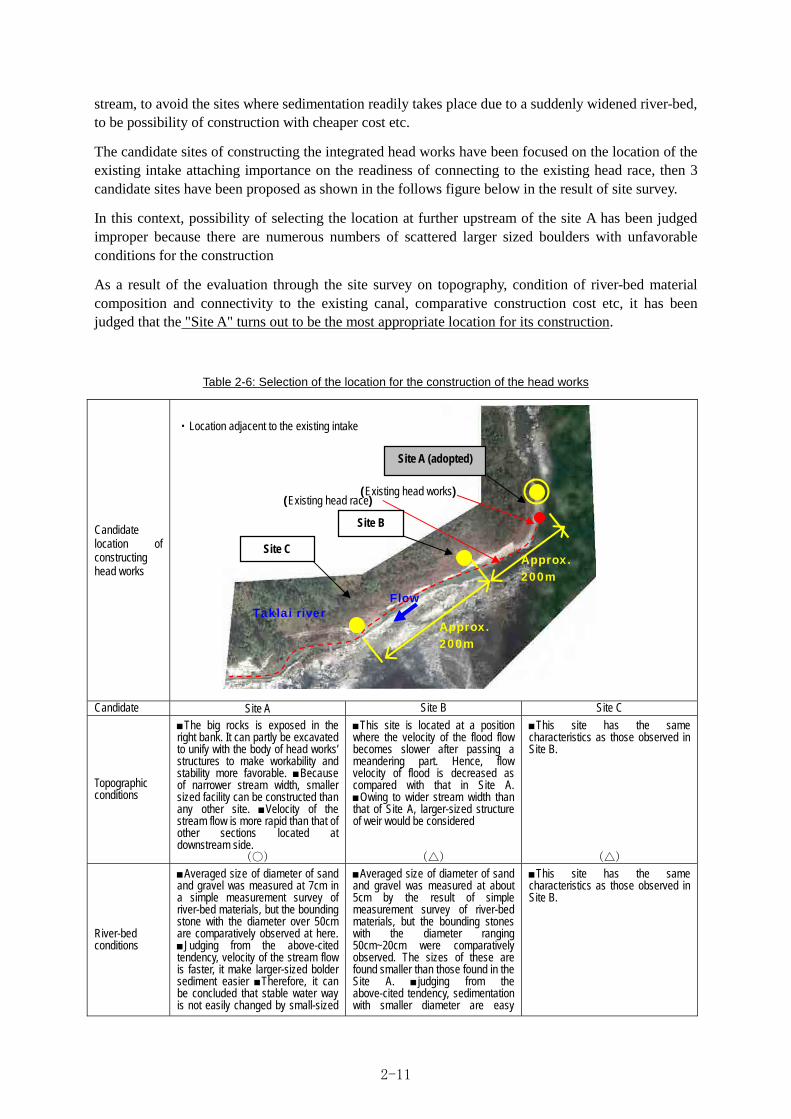
stream, to avoid the sites where sedimentation readily takes place due to a suddenly widened river-bed, to be possibility of construction with cheaper cost etc.
The candidate sites of constructing the integrated head works have been focused on the location of the existing intake attaching importance on the readiness of connecting to the existing head race, then 3 candidate sites have been proposed as shown in the follows figure below in the result of site survey.
In this context, possibility of selecting the location at further upstream of the site A has been judged improper because there are numerous numbers of scattered larger sized boulders with unfavorable conditions for the construction
As a result of the evaluation through the site survey on topography, condition of river-bed material composition and connectivity to the existing canal, comparative construction cost etc, it has been judged that the "Site A" turns out to be the most appropriate location for its construction.
Table 2-6: Selection of the location for the construction of the head works
Candidate location of constructing head works
・Location adjacent to the existing intake
Candidate Site A Site B Site C
Topographic conditions
The big rocks is exposed in the right bank. It can partly be excavated to unify with the body of head works’ structures to make workability and stability more favorable. Because of narrower stream width, smaller sized facility can be constructed than any other site. Velocity of the stream flow is more rapid than that of other sections located at downstream side.
(○)
This site is located at a position where the velocity of the flood flow becomes slower after passing a meandering part. Hence, flow velocity of flood is decreased as compared with that in Site A. Owing to wider stream width than that of Site A, larger-sized structure of weir would be considered
(△)
This site has the same characteristics as those observed in Site B.
(△)
River-bed conditions
Averaged size of diameter of sand and gravel was measured at 7cm in a simple measurement survey of river-bed materials, but the bounding stone with the diameter over 50cm are comparatively observed at here. Judging from the above-cited tendency, velocity of the stream flow is faster, it make larger-sized bolder sediment easier Therefore, it can be concluded that stable water way is not easily changed by small-sized
Averaged size of diameter of sand and gravel was measured at about 5cm by the result of simple measurement survey of river-bed materials, but the bounding stones with the diameter ranging 50cm~20cm were comparatively observed. The sizes of these are found smaller than those found in the Site A. judging from the above-cited tendency, sedimentation with smaller diameter are easy
This site has the same characteristics as those observed in Site B.
(Existing head works)
Site B
Site C
(Existing head race)
Approx. 200m
Taklai river Flow
Approx. 200m
Site A (adopted)
2-11

flood flow.
(○)
because the flow velocity is slower than that of the Site A. Though the sedimentation is also influenced by the condition of supply of sand and stones from the upstream side, the river-bed seems to be more easily shifted as compared with the Site A.
(△)
(△)
Water-intake conditions
Since the height of the river-bed is almost the same as that of the existing bed level of the head race, the height of back-water rising at the head works can be minimized. Since the narrow stream width, water can easily be caught.
(○)
The elevation of the river-bed is lower than that of the existing bed level of the head race, leading to the necessity of fairly high back-water rising by about 2meter at the head works.
(△)
Current elevation of the river-bed is further lower than that of the Site B, it becomes necessary to raise the back water level by about 4 meter at the head works.
(△)
Construction conditions
Since it is possible to make the width and height of the weir smaller size owing to the proper topographic and water intake conditions, the construction cost can be economized than other site.
(○)
Due to improper topographic and water intake conditions, wider weir with higher height and longer apron is needed, thus leading to higher construction cost as compared to the Site A.
(×)
Due to improper topographic and water intake conditions, a widest weir with highest height and longer apron is needed, thus leading the construction cost highest of the three candidate sites.
(×)
Stability against flood energy
Though this site is located at the location where flow velocity becomes rapid by topographic condition, in order to reduce the effect to the stream section can be minimized by making the height of the weir as low as possible, thus attenuating the impact of flood attack.
(○)
Though this site is located at a position where flow velocity becomes slower by its topographic condition, necessity arises to construction of higher weir, leading to disturbing of river flow, thus impacts of floods and bounding stones are considered to be greater.
(×)
Though this site is located at a position where flow velocity becomes slower by its topographic condition, it is necessary of the height of the weir. This gives a severe effect to river flow, leading to larger impacts by the floods and bounding stones.
(×)
Integrated evaluation
The scale of the facility can be made smallest among three candidate sites, and the highest water intake function can be expected. the construction cost is estimated at the lowest among these three sites. Though the site is located at the position where flood power is assumed strong, attenuation of the impact is possible by minimizing the scale of the structure.
○ (adopted location)
In this site, the scale of the structure is ranked at the second among three candidate sites. Though this site is located at a position where the flood impact can be weakened as compared to the Site A, higher rising of back water is required in order to secure the planned intake water. Thus, structure lead higher effect at flood than Site A. In addition, sand would more readily be sediment, due to the outlet out of narrow width
×
The scale of the structure in this site is largest among the 3 candidate. Though this site is located at a position where the flood impact can be weakened as compared to the Site A, higher rising of back water is required in order to secure the planned intake water. Thus, structure lead higher effect at flood than Site A. In addition, sand would more readily be sediment, due to the outlet out of narrow width
×
2-2-2-2-2 Type of the integrated head works
According to “The Standard criteria : Design of Head works in Japan”, the head works to be installed in torrential streams are roughly classified into 5 types, namely, gravitational/ natural intake type, diversion weir with sluice gate type, water cushion type, bar-screen (type of intake by underneath bar-screen, type of intake by the rear of bar-screen) and diversion weir with over-flow type guiding circle-arch face. Since among these, type of natural intake is the same type as it is currently used, and excluded from the examining evaluation while characteristics of other four types are compared and examined as shown tin the following table.
In evaluating for adaptability to the target river flow and intake function points of view, it is recommended to adopt the type of bar-screen is judged from durability against flood energy and stability of water intake for the available to highly variable discharge.
In this context, two types of bar-screen are applicable, namely, fixing bar-screen on the slope of the fixed weir or fixing it at the crest of the fixed weir. As a result of examining these from the standpoint of ease of water intake and effective use of water-head and also taking account of the scale of designed facility (collecting channel must be deepened, if bar screen is at slope of weir), the type of fixing the bar-screen at the crest of the weir is adopted.
2-12

Tab
le 2
-7: T
ype
s of
hea
d w
ork
s a
nd e
xam
ina
tion
of
wa
ter
inta
ke m
eth
od
Type
of w
eir
dive
rsio
n w
eir
Wat
er c
ussi
on
Bar
-scr
een,
wat
er in
take
un
dern
eath
the
scre
en
Bar
-scr
een,
wat
er in
take
at
the
rear
of t
he s
cree
n D
iver
sion
wea
r with
ove
r-flo
w a
t gu
idin
g ci
rcle
-arc
h fa
ce
St
ruct
ure
W
ater
inta
ke b
y in
stal
ling
a fix
ed w
eir
with
slu
ice
gate
to
orde
r to
mak
e ba
ck
wat
er
W
ater
inta
ke b
y in
stal
ling
a fix
ed w
eir
and
also
in
stal
ling
wat
er
cush
ion
unde
rnea
th th
e w
ater
dro
p
Wat
er in
let
is in
stal
led
at th
e si
de o
f the
wei
r.
W
ater
inta
ke b
y in
stal
ling
an o
verfl
ow
wei
r tra
vers
ing
the
stre
am
and
by
inst
allin
g ba
r-scr
een
at t
he t
op o
f cr
est.
Wat
er i
s co
llect
ed t
hrou
gh b
ar-s
cree
n in
to c
olle
ctin
g ch
anne
l.
T
he s
truct
ure
is s
imila
r to
the
typ
e sh
own
in
the
left,
bu
t th
e sc
reen
is
in
stal
led
at th
e sl
ope
of th
e cr
est.
Si
nce
inta
ke
quan
tity
is
as
larg
e as
ab
out
2.2m
3 /s a
nd w
ater
sho
uld
be c
olle
cted
by
wat
er-c
ushi
on
stru
ctur
e at
th
e do
wns
tream
to s
ecur
e th
e qu
antit
y.
W
ater
inta
ke b
y in
stal
ling
an o
verfl
ow
wei
r and
sha
ping
an
arch
of c
ircle
at t
he
over
flow
edg
e. W
ater
dro
ppin
g fro
m th
e ci
rcle
-edg
e is
into
the
colle
ctin
g ch
anne
l w
hich
is
inst
alle
d be
neat
h th
e ar
ch o
f ci
rcle
edg
e.
Adv
anta
ges
Th
is t
ype
can
colle
ct r
equi
red
wat
er
quan
tity,
can
keep
re
quire
d w
ater
in
co
nfor
mity
with
the
sca
le o
f irr
igat
ion
bene
ficia
ry.
th
e se
dim
enta
tion
can
be
redu
ced
by
the
flash
op
erat
ion
with
sl
uice
gat
e.
T
his
type
can
rel
ativ
ely
less
en t
he
quan
tity
of m
ixin
g sa
nd a
t its
inta
ke.
This
ty
pe
can
keep
th
e re
quire
d qu
antit
y of
wat
er i
ntak
e in
acc
orda
nce
with
the
scal
e of
the
bene
ficia
ry a
rea
Sinc
e th
e flo
od e
ffect
to w
eir i
s re
duce
d,
stab
ility
of th
e fa
cilit
y is
exp
ecte
d.
Th
e st
ruct
ural
adv
anta
ges
are
sim
ilar
to t
he t
ype
show
n in
the
left.
Sin
ce t
he
scre
en i
s in
stal
led
on t
he s
lope
of
the
wei
r, th
e sc
ale
of d
amag
es to
the
scre
en
can
be a
llevi
ated
.
S
ince
the
ove
rflow
ing
edge
has
a
shap
e of
arc
h, a
cen
trifu
gal f
orce
evo
lves
w
hen
wat
er
over
flow
s it,
th
us
it is
po
ssib
le to
mak
e le
ss le
ssen
the
degr
ee
of m
ixin
g sa
nd in
div
erte
d w
ater
.
Dis
adva
ntag
es
D
amag
es to
slu
ice
gate
s by
floo
d ar
e as
sum
ed
in
the
loca
tions
w
ith
high
er
flood
im
pact
, an
d al
so t
he s
truct
ure
is co
ncer
ned
dam
age
by
the
stru
ctur
al
dist
urba
nce
caus
ed b
y w
eir-u
p he
ight
Wat
er
inta
ke
beco
mes
im
poss
ible
on
ce s
tone
s an
d pe
bble
are
sed
imen
t on
the
wat
er c
ushi
on.
In
the
con
ditio
n of
th
is r
iver
tha
t flo
od d
isch
arge
per
uni
t w
idth
is
larg
e, t
he i
nsta
llatio
n of
thi
s st
ruct
ure
grea
tly d
istu
rbs
wat
er fl
ow, a
s a
resu
lt of
it,
le
ad
to
high
er
risk
of
dam
ages
to th
e st
ruct
ure.
S
ince
it is
inev
itabl
e to
mix
ing
of s
and
into
col
lect
ed w
ater
thr
ough
bar
-scr
een,
ne
cess
ity
som
etim
es
aris
es
to
inst
all
sedi
men
tatio
n po
nd.
The
mai
nten
ance
of
bar
-scr
een
is r
equi
red
to r
emov
e th
e cl
oggi
ng b
y sm
all b
olde
r.
P
ositi
on o
f co
llect
ing
chan
nel
in t
his
type
is
low
ered
as
com
pare
d w
ith t
he
type
sho
wn
in t
he le
ft ty
pe,
resu
lting
in
larg
er lo
ss o
f he
ad,
due
to t
he lo
wer
ed
heig
ht.
Th
e lo
wer
the
pos
ition
of
the
colle
ctin
g ch
anne
l is
, th
e th
icke
r th
e ap
ron
beco
mes
, le
adin
g to
hi
gher
co
nstru
ctio
n co
st.
Sinc
e th
e flo
od
disc
harg
e of
thi
s st
ream
is
huge
, hi
gh
prob
abilit
y of
dam
ages
to
the
part
of
wat
er c
ushi
on is
con
cern
ed.
In
this
ty
pe
of
wei
r, w
ater
in
take
qu
antit
y by
thi
s ty
pe is
lim
ited(
to le
ss
than
1m
3 /s)
The
cent
rifug
al
forc
e be
com
es
larg
er
as
stre
am
disc
harg
e in
crea
ses
and
flow
ve
loci
ty
is
acce
lera
ted,
so
wat
er in
take
itse
lf is
als
o lim
ited.
Eval
uatio
n on
th
e ad
apta
bilit
y to
th
e ta
rget
st
ream
an
d w
ater
in
take
fu
nctio
n
Sinc
e pa
rt of
flo
w
dist
urba
nce
incr
ease
s at
the
stre
am s
ectio
n un
der
the
cond
ition
that
eno
rmou
s flo
od e
nerg
y w
ith b
ound
ing
of s
tone
s an
d bo
ulde
r, fa
irly
larg
e st
reng
th is
nec
essa
ry fo
r th
e in
stal
led
stru
ctur
e.
This
typ
e is
not
so
adap
tabl
e to
this
stre
am.
Sedi
men
tatio
n of
St
one/
pe
bble
de
posi
t on
w
ater
cu
shio
n is
fu
lly
assu
mne
d, a
nd b
ecau
se e
limin
atio
n of
la
rge
ston
es a
re d
iffic
ult,
the
func
tion
of
wat
er
inta
ke
hind
ranc
e re
adily
ta
kes
plac
e.
Sin
ce th
e di
stur
bed
surfa
ce fl
ow
by
wat
er
cush
ion
durin
g flo
ods
give
s hi
gh r
isk
of d
amag
es t
o th
e st
ruct
ure.
Th
is ty
pe d
oes
not f
it to
this
stre
am.
T
he s
tabi
lity
of t
he f
acilit
y is
hig
h co
nfid
ence
be
caus
e of
th
e sm
alle
st
degr
ee
of
dist
urba
nce
to
the
stre
am
sect
ion.
Yet
, it
is s
till
nece
ssar
y to
re
info
rce
the
stru
ctur
e ag
ains
t the
hitt
ing
of
boun
ding
st
ones
.
Th
ough
m
aint
enan
ce
and
man
agem
ent
is
esse
ntia
l, st
abilit
y of
wat
er in
take
can
be
sust
aine
d.
S
and
mix
ing
is n
ot a
void
able
in
the
case
of
ba
r-scr
een
type
w
eir.
In
parti
cula
r, Th
is t
ype
has
low
er c
apac
ity
type
sho
wn
in th
e le
ft in
the
view
poi
nt o
f ef
fect
ive
use
of w
ater
hea
d, a
nd a
lso
the
cons
truct
ion
cost
is
conc
erne
d.
This
ty
pe d
oes
not e
xact
ly fi
t to
this
stre
am.
S
ince
int
ake
quan
tity
is s
truct
ural
ly
limite
d,
this
ty
pe
cann
ot
secu
re
the
desi
gn
inta
ke
quan
tity.
Beca
use
flow
ve
loci
ty in
crea
ses
durin
g ra
iny
seas
on, i
t m
akes
wat
er in
take
diff
icul
t.
Thi
s ty
pe
does
t not
fit t
o th
is s
tream
.
Judg
men
t △
×
○
△
×
2-13

2-2-2-2-3. Examination on the elevation of major parts of structures
(1) The crest of the weir
The water collecting channel is placed at the crest of the weir in the type of intake underneath
bar-screen to be adopted in the facility plan. Therefore it is designed to avoid mixing of mud/ sand
during water intake, and also to make less the effect of disturbance during floods as far as possible. In
order to avoid disturbing effect during floods, it is better to make the elevation of the weir crest as
close to the river-bed as possible, however, it become concerned about the mixing sand into the intake
water thus, it becomes necessary to keep the weir crest higher to some extent than the elevation of the
river-bed.
At the planned site has a
topography shown in the
right figure, the feature of
site is indicates outcrops at
the right bank and in the left
is seen the shallow sand
bank. The elevation of the
weir crest is determined by
this observation on the elevation of sand bank. Hence, the elevation of the weir crest is designed at EL
301.5m.
(2) The weir body
The elevation of the surface of the apron of weir is determined at EL 300.5m, around the same
elevation of the current river-bed, in order to avoid giving excessive impact to the weir by flood.
The elevation of foundation of the
weir body is to be judged by the
geological survey. The result of
this survey indicates that overall
geological feature in the planned
site are considered as those in
which stone/bolder and pebble
have been settled. Particularly,
according to the state of core
samples collected from the current
river-bed by a boring survey, small
and medium sized stone/boulder
and pebble are observed ranging
the depth of EL 299~ about EL 298m, and below these depth relatively larger sized stone/bolder and
pebble predominate is considered as the principle composition by the core samples, in addition these
strata are observed having compacted density. Therefore, the elevation of footing of weir body is
Fig 2-4: Transversal cross section of planned site
Fig 2-5: Profile of downstream side
Planned site of Head works
約110m
EL 298m~297m
changingpoint of riverbed by hugestone
FLOW
V=1:150H=1:1,500
Assumeddescended bedlevel (1/60)
Level of embedded foundationEL 297.5
2-14
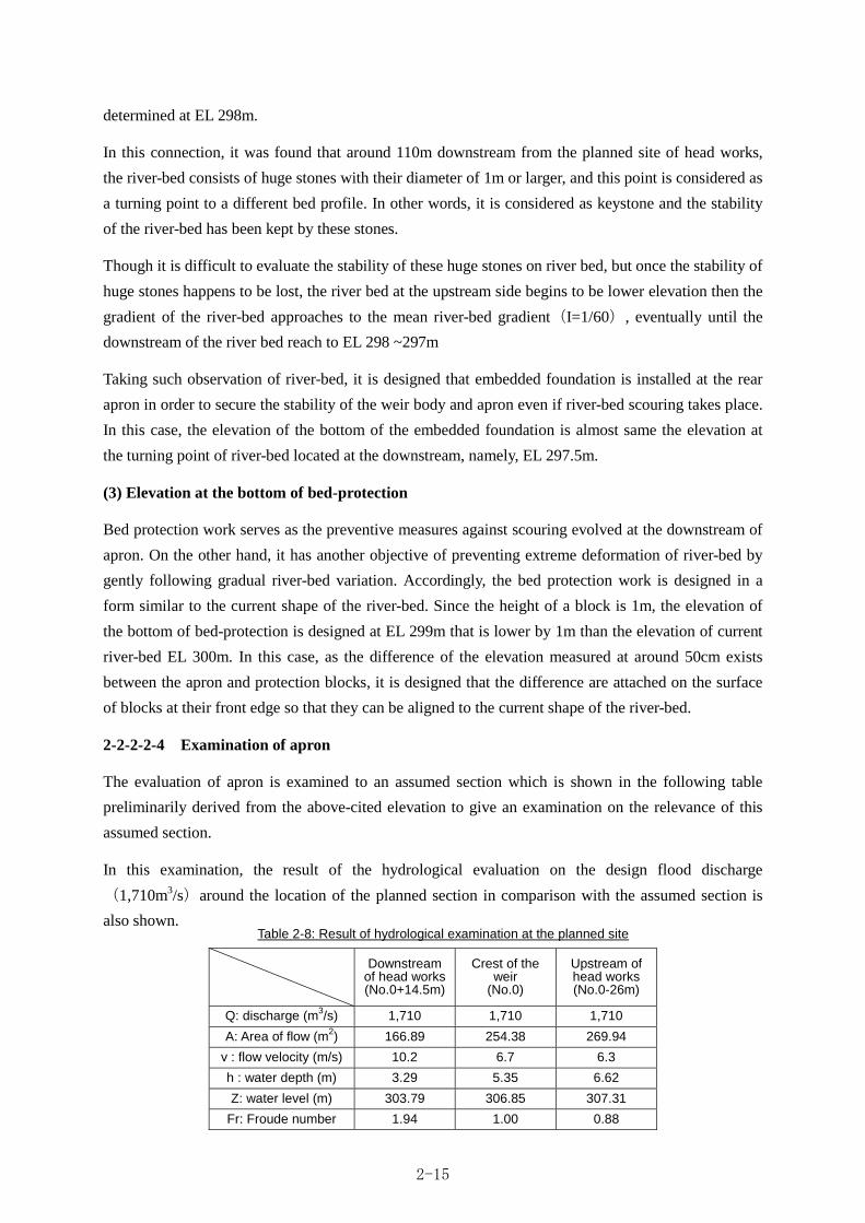
determined at EL 298m.
In this connection, it was found that around 110m downstream from the planned site of head works,
the river-bed consists of huge stones with their diameter of 1m or larger, and this point is considered as
a turning point to a different bed profile. In other words, it is considered as keystone and the stability
of the river-bed has been kept by these stones.
Though it is difficult to evaluate the stability of these huge stones on river bed, but once the stability of
huge stones happens to be lost, the river bed at the upstream side begins to be lower elevation then the
gradient of the river-bed approaches to the mean river-bed gradient(I=1/60), eventually until the
downstream of the river bed reach to EL 298 ~297m
Taking such observation of river-bed, it is designed that embedded foundation is installed at the rear
apron in order to secure the stability of the weir body and apron even if river-bed scouring takes place.
In this case, the elevation of the bottom of the embedded foundation is almost same the elevation at
the turning point of river-bed located at the downstream, namely, EL 297.5m.
(3) Elevation at the bottom of bed-protection
Bed protection work serves as the preventive measures against scouring evolved at the downstream of
apron. On the other hand, it has another objective of preventing extreme deformation of river-bed by
gently following gradual river-bed variation. Accordingly, the bed protection work is designed in a
form similar to the current shape of the river-bed. Since the height of a block is 1m, the elevation of
the bottom of bed-protection is designed at EL 299m that is lower by 1m than the elevation of current
river-bed EL 300m. In this case, as the difference of the elevation measured at around 50cm exists
between the apron and protection blocks, it is designed that the difference are attached on the surface
of blocks at their front edge so that they can be aligned to the current shape of the river-bed.
2-2-2-2-4 Examination of apron
The evaluation of apron is examined to an assumed section which is shown in the following table
preliminarily derived from the above-cited elevation to give an examination on the relevance of this
assumed section.
In this examination, the result of the hydrological evaluation on the design flood discharge
(1,710m3/s)around the location of the planned section in comparison with the assumed section is
also shown.
Downstream
of head works(No.0+14.5m)
Crest of the weir
(No.0)
Upstream of head works (No.0-26m)
Q: discharge (m3/s) 1,710 1,710 1,710
A: Area of flow (m2) 166.89 254.38 269.94
v : flow velocity (m/s) 10.2 6.7 6.3
h : water depth (m) 3.29 5.35 6.62
Z: water level (m) 303.79 306.85 307.31
Fr: Froude number 1.94 1.00 0.88
Table 2-8: Result of hydrological examination at the planned site
2-15
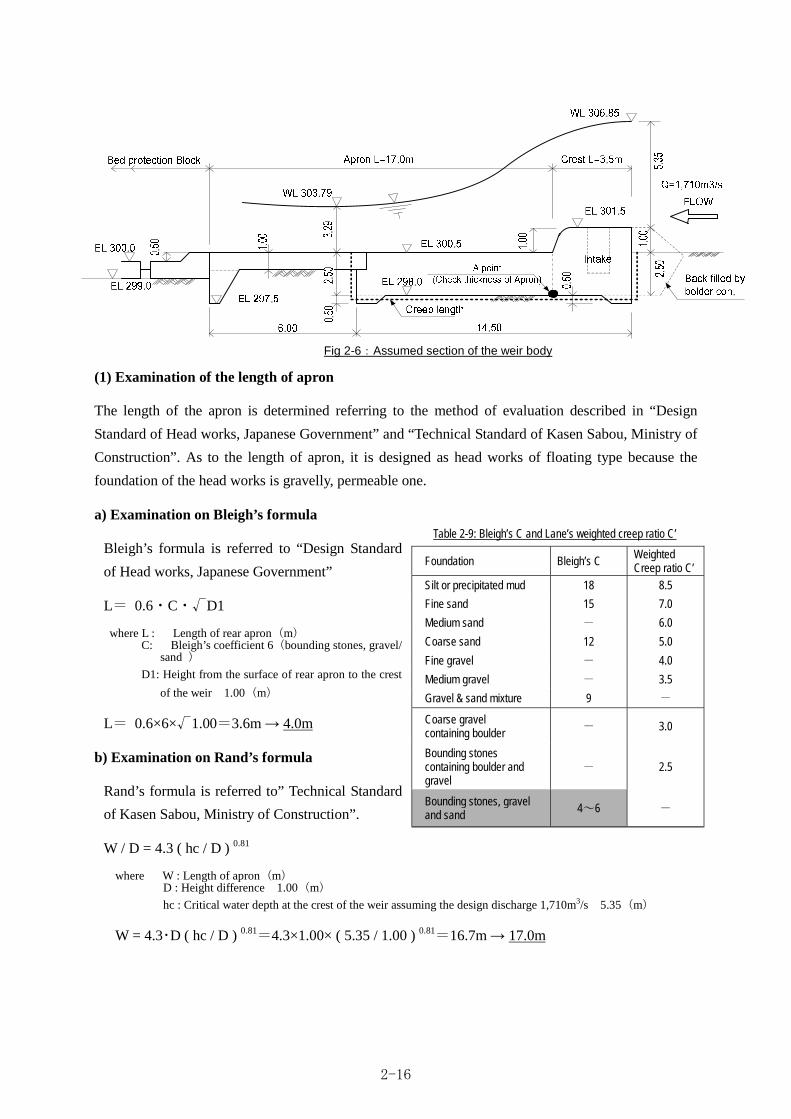
(1) Examination of the length of apron
The length of the apron is determined referring to the method of evaluation described in “Design
Standard of Head works, Japanese Government” and “Technical Standard of Kasen Sabou, Ministry of
Construction”. As to the length of apron, it is designed as head works of floating type because the
foundation of the head works is gravelly, permeable one.
a) Examination on Bleigh’s formula
Bleigh’s formula is referred to “Design Standard
of Head works, Japanese Government”
L= 0.6・C・√D1
where L : Length of rear apron(m) C: Bleigh’s coefficient 6(bounding stones, gravel/
sand )
D1: Height from the surface of rear apron to the crest
of the weir 1.00(m)
L= 0.6×6×√1.00=3.6m 4.0m
b) Examination on Rand’s formula
Rand’s formula is referred to” Technical Standard
of Kasen Sabou, Ministry of Construction”.
W / D = 4.3 ( hc / D ) 0.81
where W : Length of apron(m) D : Height difference 1.00(m)
hc : Critical water depth at the crest of the weir assuming the design discharge 1,710m3/s 5.35(m)
W = 4.3・D ( hc / D ) 0.81=4.3×1.00× ( 5.35 / 1.00 ) 0.81=16.7m 17.0m
Foundation Bleigh’s C Weighted Creep ratio C’
Silt or precipitated mud 18 8.5
Fine sand 15 7.0
Medium sand - 6.0
Coarse sand 12 5.0
Fine gravel - 4.0
Medium gravel - 3.5
Gravel & sand mixture 9 -
Coarse gravel containing boulder
- 3.0
Bounding stones containing boulder and gravel
- 2.5
Bounding stones, gravel and sand
4~6 -
Table 2-9: Bleigh’s C and Lane’s weighted creep ratio C’
Fig 2-6:Assumed section of the weir body
2-16

c) Determination of apron length
From the result obtained as above by means of
both formulas, the examination result is
summarized in the table shown in the right, thus
the length of the rear apron is determined as :
L=17.0m.
(2) Examination on piping
Examination on piping is made by means of the assumed section of weir body mentioned above. The
method of examination is derived from Bleigh’s and Rand’s formulas indicated in “Design Standard of
Head works, Japanese Government”. It is concluded from the following examinations that the
assumed section is judged safe against piping.
・Bligh’s method
S ≧ C・ΔH
where S: Length of path of percolation measured along the foundation face of the weir(m) Σ V=2.50 + 2.50=5.00m Σ H=14.50m(length of weir body at upstream side) S = Σ v + Σ H = 5.00m + 14.50m = 19.50m C : Bleigh’s coefficient 6[above-cited]
Δ H : Maximum difference of water level between upstream and downstream sides 3.06(m)
6×3.06 = 18.36(m) ≦ S = 19.50(m) judged as safe
・Lane’s method
L ≧ C'’・ΔH
where : weighted length of percolation path(m) L =Σ V + 1/3・Σ H=5.00m+1/3×14.50m=9.83m V : Length of percolation path to vertical direction(45° or steeper) 6.00(m): the same as the examination by
Bleigh’s formula H : Length of percolation path to horizontal direction(45° or gentler)14.50(m): the same as the examination by
Bleigh’s formula C' : Weighted creep ratio 3.0(bounding stones containing boulder and gravel: referred to above table)
ΔH : Maximum difference of water level between upstream and downstream 3.06(m)
3.0×3.06 = 9.18(m) ≦ L = 9.83m judged as safe
(3) Examination on the thickness of apron
The examination on the thickness of apron is made referring to “Design Standard of Head works,
Japanese Government” It is concluded from the following examinations that the safety of the assumed
section is secured.
t = 4/3 ×(ΔH – Hf)/(γ-1)
where : thickness at the point in consideration(m) ΔH : Maximum difference of water level between upstream and downstream sides 3.06(m) Hf = H / S × S' : Head loss of seepages up to the point in consideration(m) γ : Specific gravity of the material of weir body and apron 2.35 4/3 : Rate of safety
Method of examination
Length of apron Judgment
Bleigh’s formula 4.0m
Rand’s formula 17.0m ○ (adopted)
Table 2-10: Apron length by means of both formulas
2-17

S : Total designed length of path of percolation: 19.50(m): the same as the examination by Bleigh’s formula
S' : Length of path of percolation to any point(m)
・Examination at the point A(downstream of the fixed weir)
3.06 HfA =
19.50×(2.50 + 3.50)= 0.94(m)
4 3.06-0.94 TA =
3 ×
2.35-1 =2.09(m)≦ 2.50(m) OK
2-2-2-2-5 Examination of bed pitching
(1) Examination on the length of bed protection
Bed protection is a facility to sustain the stability of river-bed against the supercritical flow which is
occurred by the hydraulic jump phenomenon in order to dissipate the water energy. Therefore, a length
of protected bed is hydraulically required enough to make hydraulic jump. However, since the target
river is a torrential stream with an average river-bed gradient of 1/60, river flow during floods
becomes almost jet flow, hydraulic jump required for energy dissipation does not hydraulically takes
place.
By this reason, the scale of the bed protection is designed at minimum requirement for the purpose of
preventing scouring at downstream apron or disturbance at river-bed surface.
In this design, the length of the bed protection is examined by means of Bligh’s formula in line with
“Design Standard of Head works, Japanese Government”.
L = Lb - La
Lb = 0.67・C・ (Ha・q)・f
where L : length of seed protection(m) Lb : Total length to protect including the length of the apron "La" and that of bed protection "L"(m) a : length of rear apron(m) Ha : Maximum difference of water level between upstream and downstream 3.06(m) q : Discharge per unit width derived from design flood discharge(Q = 1,710m3/s)(I m3/s/m) B : Width of waterway at the design section 45.3m = 39.8m + 5.5m q = Q / B = 1,710m3/s ÷ 45.3m = 37.7 m3/s/m f : Safety ratio in the case of fixed weir 1.0
C : Bligh’s coefficient by type of foundation ground 6
hence: Lb = 0.67×6× (3.06×37.7)×1.0 = 43.18 m(Required length including apron and bed
protection)
La = 17.00m (Total length of apron)
L = 43.18m – 17.00 = 26.17 m
From the result of above-mentioned examination, the necessary length for bed protection 26.17m
or longer is adopted as the extent of working bed protection.
2-18

(2) Examination of blocks for bed protection
Unit weight of a block is determined through the examination of the stability per piece of block in
conformity with the following formula described in “Design Standard of Head works, Japanese
Government”.
2g・W Ua=(
3.19・A )1/2
where A : Area of collision of river flow(m2) W : weight of a piece of block(t) Ua : Allowable flow velocity (m/s)
Weights of a piece of block corresponding to various velocities are given in the following table. In this
regard, because the block is manufactured by cast-in-place concrete, conventional crop-shaped block
is employed for this type of structure.
Table 2-11: Weight of a piece of block and allowable flow velocity
Specification 3 ton 8 ton 8 ton × 2 connected
Size of block (m)
Weight of block 3.4 ton 8.2 ton 16.4 ton Area of block surface collided by flow
1.70 x 0.2 = 0.34 m2 2.80 x 0.2 = 0.56 m2 (2.80 +2.10) x 0.2+ = 0.98 m2
Maximum allowable velocity 7.8 m/s 9.5 m/s 10.2 m/s
Since the flow velocity likely to occur at the downstream of the head works during the design flood
discharge is estimated at about(1,710m3/s)10 m/s as a result of hydraulic calculation, blocks of a
specification with combined two pieces (8 ton/piece × 2) is adopted, because it can allow the
maximum flow velocity of 10.2m/s.
2-2-2-2-6 Examination of collecting channel
The design of the type of water intake below bar screen is based on “Design Standard of Head works,
Japanese Government”.
(1) Design of bar-screen
In “Design Standard of Head works, Japanese Government”, the interval of
bars used for the type of intake beneath the bar screen is generally given in
a range between 20mm and 30mm or so, however, it also points out that
choking often takes place over the screen. Therefore, taking account of
bar-intervals in case studies and of current state of river-bed sand and
2.80
Fig 2-7:Section of screen
2-19
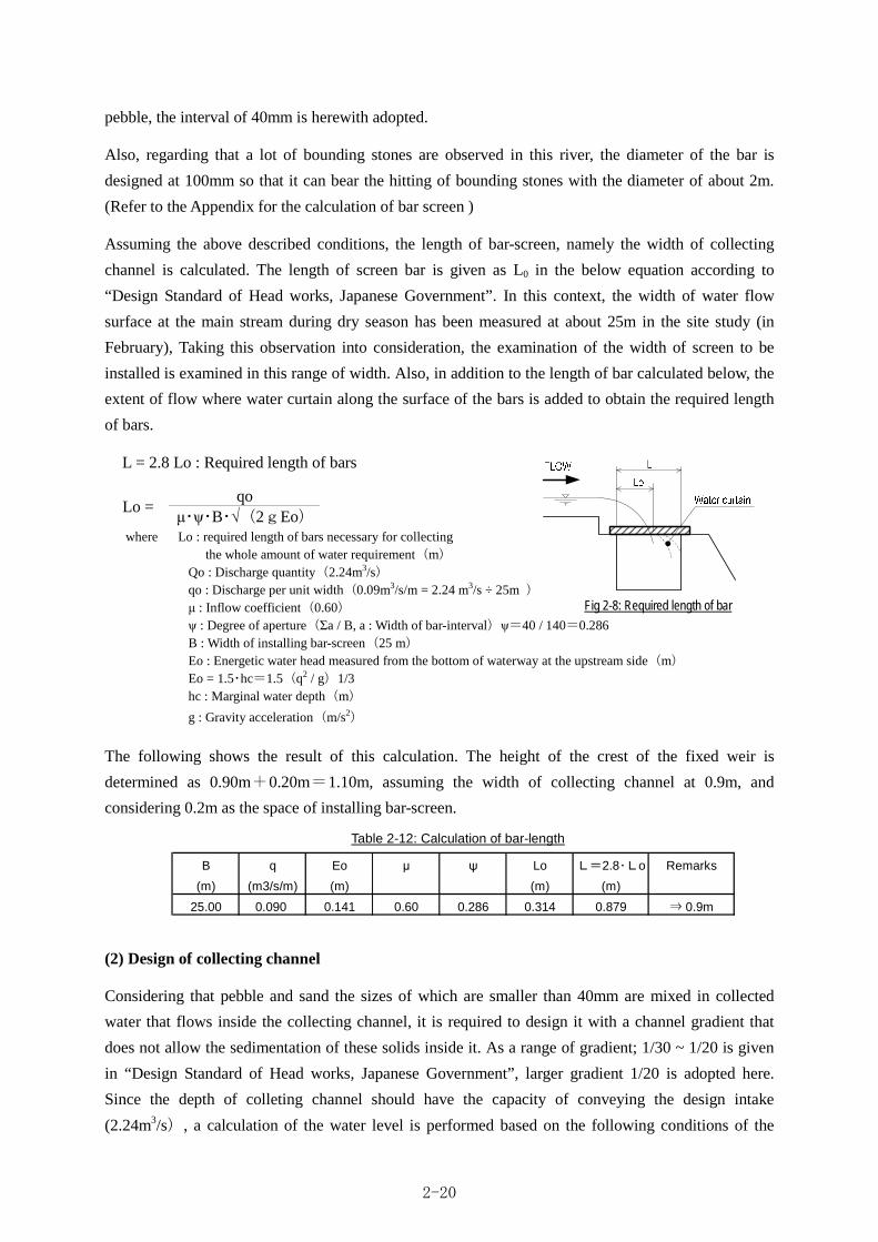
pebble, the interval of 40mm is herewith adopted.
Also, regarding that a lot of bounding stones are observed in this river, the diameter of the bar is
designed at 100mm so that it can bear the hitting of bounding stones with the diameter of about 2m.
(Refer to the Appendix for the calculation of bar screen )
Assuming the above described conditions, the length of bar-screen, namely the width of collecting
channel is calculated. The length of screen bar is given as L0 in the below equation according to
“Design Standard of Head works, Japanese Government”. In this context, the width of water flow
surface at the main stream during dry season has been measured at about 25m in the site study (in
February), Taking this observation into consideration, the examination of the width of screen to be
installed is examined in this range of width. Also, in addition to the length of bar calculated below, the
extent of flow where water curtain along the surface of the bars is added to obtain the required length
of bars.
L = 2.8 Lo : Required length of bars
qo Lo =
μ・ψ・B・ (2gEo)where Lo : required length of bars necessary for collecting the whole amount of water requirement(m)
Qo : Discharge quantity(2.24m3/s) qo : Discharge per unit width(0.09m3/s/m = 2.24 m3/s ÷ 25m ) μ : Inflow coefficient(0.60) ψ : Degree of aperture(Σa / B, a : Width of bar-interval)ψ=40 / 140=0.286 B : Width of installing bar-screen(25 m) Eo : Energetic water head measured from the bottom of waterway at the upstream side(m) Eo = 1.5・hc=1.5(q2 / g)1/3 hc : Marginal water depth(m)
g : Gravity acceleration(m/s2)
The following shows the result of this calculation. The height of the crest of the fixed weir is
determined as 0.90m+0.20m=1.10m, assuming the width of collecting channel at 0.9m, and
considering 0.2m as the space of installing bar-screen.
(2) Design of collecting channel
Considering that pebble and sand the sizes of which are smaller than 40mm are mixed in collected
water that flows inside the collecting channel, it is required to design it with a channel gradient that
does not allow the sedimentation of these solids inside it. As a range of gradient; 1/30 ~ 1/20 is given
in “Design Standard of Head works, Japanese Government”, larger gradient 1/20 is adopted here.
Since the depth of colleting channel should have the capacity of conveying the design intake
(2.24m3/s), a calculation of the water level is performed based on the following conditions of the
B q Eo μ ψ Lo L=2.8・Lo Remarks
(m) (m3/s/m) (m) (m) (m)
25.00 0.090 0.141 0.60 0.286 0.314 0.879 ⇒ 0.9m
Table 2-12: Calculation of bar-length
Fig 2-8: Required length of bar
2-20

Photo 2-1: State of the river-bed at planned site of head k
examination to determine the required depth.
L : Width of the collecting channel to the flow direction(0.90m) B : Width of the collecting channel to the direction of traversing the river(25.0m) n : Roughness coefficient of the collecting channel(0.016) I : Gradient of the collecting channel(1/20) Q : Discharge under examination(2.24 m3/s) ho : Water depth at the start of calculation(1.318m)※This value is equal to the sum of the water depth equivalent to the design discharge and 60% of the velocity head
The water depth of the downstream edge of the channel is calculated at 1.318 m from the above given
dimensions. Therefore, taking account of freeboard against the undulation of water surface and the
mixing sand and pebble, the depth of the collecting channel is designed at 1.318 m + 0.50 m = 1.818
m 1.80m. In this regard, water depth at the downstream edge of the channel is designed at 1.80m +
0.50 m = 2.30 m considering the thickness of the top cover of culvert (0.5m) for the purpose of
connecting the channel to the culvert at the downstream. The depth of the collecting channel at the
upstream side is designed at H = 2.30m - 1/20 × 25.00m = 1.05 m because the gradient of the channel
is I=1/20.
The following shows the traversing section of collecting channel.
2-2-2-2-7 Surface protection work
(1) Necessity of constructing surface protection
work
Taklai river represents a torrential stream with
mountains of the altitude 2,000 ~ 3,000m as its
watershed. Huge rocks/ stones with their diameters
over 2m are scattered over the river-bed, large heap of
sand/ gravel deposits are also identified there (refer to
the photo).
In the case of installing structures under such conditions, it is suitable to judge the relevance of
Table 2-13: Result of the calculation tracing the water surface inside the channel
Fig 2-9: Section of collecting channel
Water depth
h(m)
D.S 0.00 0.000 2.240 1.318 1.187 3.537 0.335 1.888 0.182 0.000 1.500
U.S 25.00 1.250 0.172 0.310 0.279 1.519 0.183 0.617 0.019 0.004 1.579
No.Accumulatedistance (m)
Bed level (m) Q(m3/s)Wetted
perimeter(m)Hydraulicradius (m)
Area forflow (m2)
Velocity(m/s)
hv(m) hf(m) EL(m)
2-21

constructing them by considering correlation between such environmental conditions as density or size
of bounding stones or river-bed gradient and the relative strength of the planned structures. However,
concrete and numerical evaluation is difficult in the lack of streamlined references related to this
domain.
As a conventional clue for judgment, a tendency
as tabulated above table can be obtained from the
examined relation between the current width of the
river and the target flood discharge
(1,710m3/s).This table shows example cases that
have statistically been studied and listed in “Design
Standard of Head works, Japanese Government”
and “Technical Standard of Kasen Sabou, Ministry
of Construction”. The conditions found in this
target site and the exemplified cases in Japan are not necessarily accorded, although it is evaluated that
assuming the flood discharge of 1,710m3/s the corresponding width of the stream should mostly range
120m~160m (in this assumption, high discharge and the flood are deemed as the same). Whereas, the
example of Taklai River gives too narrow width, namely about 60m.
Similarly, a calculation based on this table for the discharge per unit width gives 28.5m3/s/m in the
case of Taklai River, implying that the scale of the force of river-flow and energy during floods
accompanied by bounding stones and pebble are considered fairly large as compared with ordinary
streams listed up in the example cases.
In other words, in constructing concrete structures in the target river, it is readily imagined that
collided/ flood damages of the structures will be resulted in a few years unless protective or
reinforcing measures are applied, eventually leading to early loss of water intake function. In particular,
one of the reasons why medium and small scaled fluvial structures like weirs has not been constructed
in Bhutan.
Accordingly, in designing head works, it is planned to lay relevant protecting/ reinforcing materials
over the surface of the structure body where flood flow directly contacts. Work measures to be
proposed for this objective are to be judged with referring to the examples of construction work
actually implemented as protection measures shown in “Design Standard of Head works, Japanese
Government”.
General causes that bring wearing and deformation over the surface of apron are the actions of impacts,
abrasion, cavitations etc by the flowing down of sand and gravel. Particularly, Taklai River has a
character of accompanying bounding stones under the condition that huge flood discharge passes
narrow stream width, and this is why impact shock of bounding stones is greatly concerned as the
cause of deformation.
Even though a construction work existed that is semi-permanently durable against impact shock of
Designed high discharges (m3/s)
Width of river (m)
Discharge per unit width
(m3/s)
300 40~60 7.5~5.0
500 60~80 8.3~6.3
1,000 90~120 11.1~8.3
2,000 160~220 12.5~9.1
5,000 350~450 14.3~11.1
This site (Taklai River)
1,710 About 60 28.5
Table 2-14: Examples related to designed high discharges and stream idth
2-22

huge bounding stones under the above-cited conditions, it may be physically difficult or becoming too
large scale and economically consumptive. Therefore, it would be considered relevant to apply
measures that can allow to make a premise of regular management of repairs and maintenance. To
realize this measures, the work that can provide certain strength that is readily repairable, at the same
time that can repair with cheap materials is considered suitable. Accordingly, in selecting the method
of protection work for the apron, attention will be paid to the following criteria based on the basic
principles:
1. A premise is placed to be repaired and maintained regularly for apron.
2. In order to be repaired readily, the serious damage is prevented and the materials that can
readily be available in Bhutan are used.
3. Protection work for apron is selected in the process of the evaluation on the effect against
damages not only by abrasion but also by collided shock by bounding stones.
(2) Kind of protection work for apron
Various kinds of apron protection methods have been proposed from past example cases as shown in
“Design Standard of Head works, Japanese Government”. According to this standard, surface
protection methods are roughly classified into three categories, namely ①making the anti-abrasive
coating layer over the surface of concrete,②mixing anti-abrasive material in the cast concrete and ③
improving quality of concrete. In this evaluation, two more methods are added, namely “high strength
concrete containing rail method” and “high strength precast concrete method” as implemented
examples in Japanese head works.
Table 2-15: Kind of work methods for apron surface protection
Methods listed in “Design Standard of Head works, Japanese Government”
Method Method to form anti-abrasive film at the surface of concrete
Method to mix anti-abrasive material in concrete
Method to improve quality of concrete
Other works with actual examples of performances
Work
a) Stone protection work b) Steel protection work c) Epoxy resin-mortar d) Elastic sheet work e) Cast steel plate work f) Hyper-strength fiber
reinforced concrete
g) Iron powder concrete work
h) Steel grid work
i) Vacuum concrete work j) Granulisic concrete
work k) High strength concrete work
l) high strength concrete containing rail method
m) high strength precast concrete method
①Forming anti-abrasive film/coating at the surface of concrete.
a) Stone protection method
In this stone protection method in Japan, protection with cut stone, cobble stone, query stone etc
have hitherto been practiced providing excellent anti impact and anti-abrasive work. This was used
until around 1960, but recently rarely utilized due to technical degradation of masonry, difficulty of
procuring high quality stone materials, high construction costs and issue arising from detachment
from basement concrete. On the other hand, in development country where it is easy to obtain the
suitable stone, the masonry structure can be observed relatively.
2-23
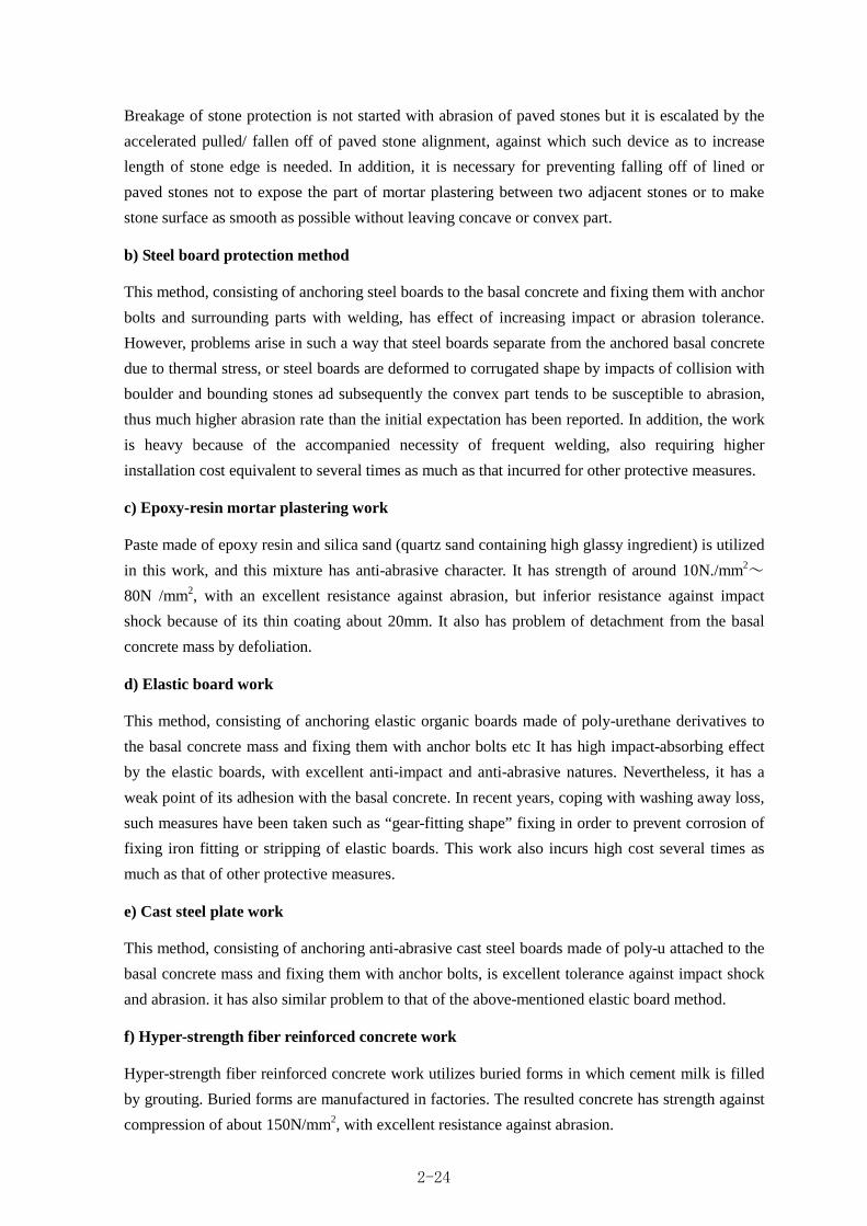
Breakage of stone protection is not started with abrasion of paved stones but it is escalated by the
accelerated pulled/ fallen off of paved stone alignment, against which such device as to increase
length of stone edge is needed. In addition, it is necessary for preventing falling off of lined or
paved stones not to expose the part of mortar plastering between two adjacent stones or to make
stone surface as smooth as possible without leaving concave or convex part.
b) Steel board protection method
This method, consisting of anchoring steel boards to the basal concrete and fixing them with anchor
bolts and surrounding parts with welding, has effect of increasing impact or abrasion tolerance.
However, problems arise in such a way that steel boards separate from the anchored basal concrete
due to thermal stress, or steel boards are deformed to corrugated shape by impacts of collision with
boulder and bounding stones ad subsequently the convex part tends to be susceptible to abrasion,
thus much higher abrasion rate than the initial expectation has been reported. In addition, the work
is heavy because of the accompanied necessity of frequent welding, also requiring higher
installation cost equivalent to several times as much as that incurred for other protective measures.
c) Epoxy-resin mortar plastering work
Paste made of epoxy resin and silica sand (quartz sand containing high glassy ingredient) is utilized
in this work, and this mixture has anti-abrasive character. It has strength of around 10N./mm2~
80N /mm2, with an excellent resistance against abrasion, but inferior resistance against impact
shock because of its thin coating about 20mm. It also has problem of detachment from the basal
concrete mass by defoliation.
d) Elastic board work
This method, consisting of anchoring elastic organic boards made of poly-urethane derivatives to
the basal concrete mass and fixing them with anchor bolts etc It has high impact-absorbing effect
by the elastic boards, with excellent anti-impact and anti-abrasive natures. Nevertheless, it has a
weak point of its adhesion with the basal concrete. In recent years, coping with washing away loss,
such measures have been taken such as “gear-fitting shape” fixing in order to prevent corrosion of
fixing iron fitting or stripping of elastic boards. This work also incurs high cost several times as
much as that of other protective measures.
e) Cast steel plate work
This method, consisting of anchoring anti-abrasive cast steel boards made of poly-u attached to the
basal concrete mass and fixing them with anchor bolts, is excellent tolerance against impact shock
and abrasion. it has also similar problem to that of the above-mentioned elastic board method.
f) Hyper-strength fiber reinforced concrete work
Hyper-strength fiber reinforced concrete work utilizes buried forms in which cement milk is filled
by grouting. Buried forms are manufactured in factories. The resulted concrete has strength against
compression of about 150N/mm2, with excellent resistance against abrasion.
2-24

② Mixing anti-abrasive material in concrete
g) Iron powder concrete work
Soon after casting concrete, iron powder is spread over cast concrete surface as thick as 3 ~ 4 mm
so that iron can be unified with cast concrete mass. However, detachment is readily induced
because of iron has different expansion coefficient from that of concrete. This method does not give
so much excellent resistance against abrasion and is susceptible to impact damages.
h) Steel grid work
This method only replaces a part of fine aggregates of ordinary concrete with specially selected
iron particles, thus having almost the same characteristics as those of iron-powder concrete.
Therefore, it has not greater resistance against abrasion, and also it has weak resistance against
impact.
③ Improving quality of concrete
i) Vacuum concrete work
Immediately after casting concrete, moisture contained in concrete is absorbed out fro the surface
by vacuum treatment, thus making water cement ratio in concrete smaller and this leads to
improved quality of cast concrete itself (strength etc). Though the treatment can increase strength
against compression and resistance against abrasion by both 20 ^ 30%, it has weak resistance
against impact. Therefore, this method is suitable to rivers where less boulder / sand and gravel
bounding.
j) Granulisic concrete work
This work was utilized for the purpose of making crest of erosion and torrent control dams more
resistant against abrasion or of repairing weir body and apron. Water cement ratio in this work is
made extremely smaller without employing fine aggregates but only coarse aggregates and cement
paste are used for kneading so as to provide rich mix concrete with water cement ratio at around
30%. This mixture is excellent resistance against abrasion and impact, but as it is a kind of
hard-kneaded concrete with a slump of nearly 0cm, it has inferior workability in the case of using
large amount of concrete though it is suitable for small scaled work like repairing etc.
k) High strength concrete work
Rich mix concrete with lowered water cement ratio is employed in this work, showing both
excellent anti-abrasive and highly impact resistant nature. Nevertheless, in the case of construction
in rivers with abundant bounding stones, this material is often used combined with other members,
or other method is often selected. Construction work with this concrete is similar to that of ordinary
concrete, thorough curing after casting is essential because rich mix is used in this case, otherwise
risk of evolving cracks would increase. In the actual examples the strength of 30~50N/mm2 and
casting thickness of 30~50cm have been adopted. In particular, in the case of overseas works,
2-25

around35N/mm2 has been adopted partly because difficulty arises in securing high quality of the
materials or favorable work environment (referring to the performances in East Timor).
④ Other works with actual examples of performances
l) High strength concrete containing rail method
In addition to characteristics that high strength concrete is equipped, rail used for railway, a
member with high stiffness is placed in a screen shape over the surface for the purpose of
improving resistance against impact and high strength concrete is cast in between the placed rail.
m) High strength precast concrete work
This work consists of concrete sheets manufactured in factories that are carried to the site, then
filling cement milk by grouting after installing them on the surface of structure to be protected with
anchor bolts. The strength attained by this work is equivalent to that of high strength concrete,
namely 100n/mm2.
(3) Evaluation of protection work of the apron
Various case examples are available on the protecting work of apron surface as given above the
evaluation In here. The method of protection work for Apron is evaluated by following indicators, with
taking consideration current state of the site.
Table 2-16: Evaluation indicators based on the basic principles of the design
Evaluation indicator Contents of evaluation Resistance against abrasion Evaluation of resistance against abrasion caused by sand/ pebble and stone, referring to
the descriptions in existing references Resistance against impact Evaluation of resistance against impact shock caused by sand/ pebble and stone,
referring to the descriptions in existing references Workability Evaluating readiness/ difficulty of work in Japanese construction cases Material procurement Evaluating readiness/ difficulty of procurement in Bhutan Operation & maintenance Evaluating readiness/ difficulty in the case of repairing and maintaining facilities in
Bhutan
The following table shows the comparison on the above-listed evaluation indicators.
2-26
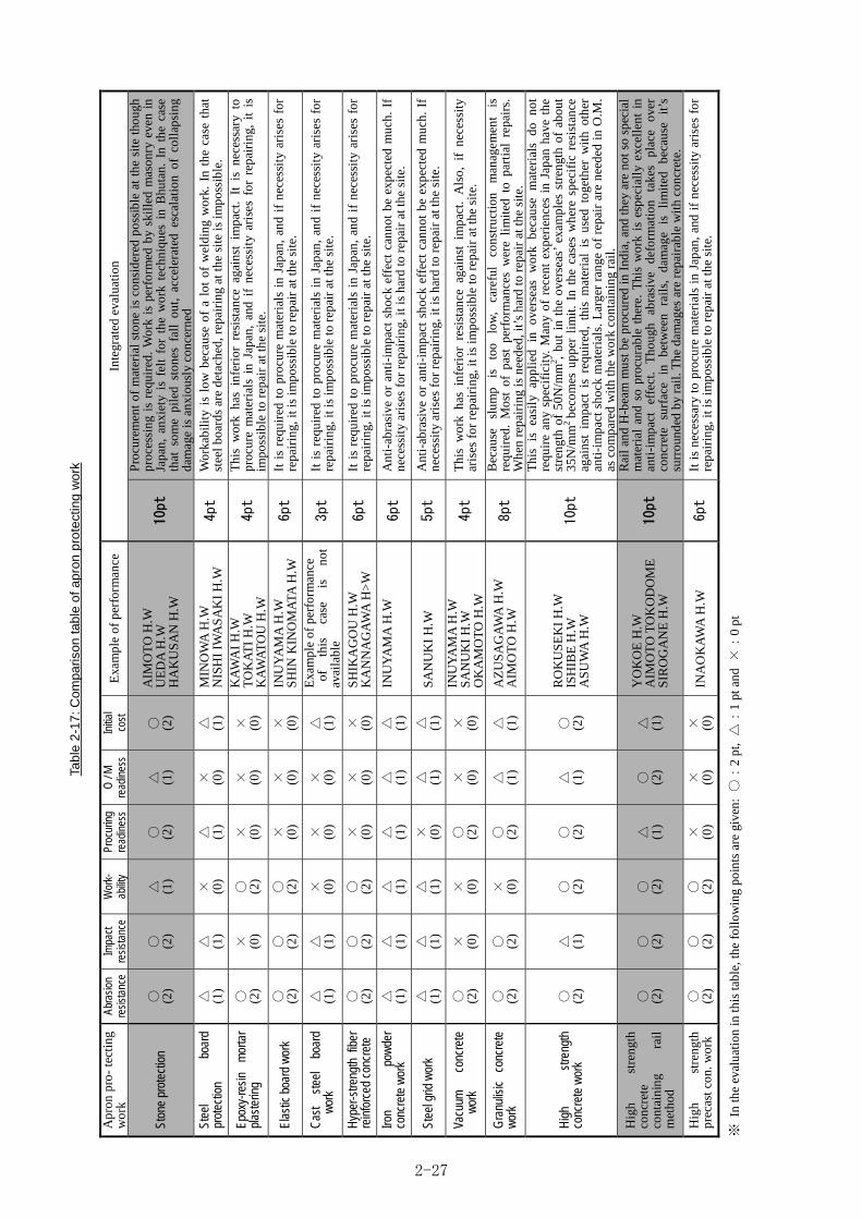
Tab
le 2
-17
: C
ompa
rison
tab
le o
f a
pro
n p
rote
ctin
g w
ork
Apr
on p
ro-
tect
ing
wor
k Ab
rasi
on
resi
stan
ce
Impa
ct
resi
stan
ce
Wor
k-
abilit
y Pr
ocur
ing
read
ines
s O
/ M
re
adin
ess
Initi
al
cost
E
xam
ple
of p
erfo
rman
ce
Inte
grat
ed e
valu
atio
n
Ston
e pr
otec
tion
○
(2)
○
(2)
△
(1)
○
(2)
△
(1)
○
(2)
AIM
OT
O H
.W
UE
DA
H.W
H
AK
US
AN
H.W
10pt
Pro
cure
men
t of
mat
eria
l st
one
is c
onsi
dere
d po
ssib
le a
t th
e si
te t
houg
h pr
oces
sing
is
requ
ired
. W
ork
is p
erfo
rmed
by
skil
led
mas
onry
eve
n in
Ja
pan,
anx
iety
is
felt
for
the
wor
k te
chni
ques
in
Bhu
tan.
In
the
case
th
at s
ome
pile
d st
ones
fal
l ou
t, ac
cele
rate
d es
cala
tion
of
coll
apsi
ng
dam
age
is a
nxio
usly
con
cern
ed
Stee
l bo
ard
prot
ectio
n △
(1
) △
(1
) ×
(0
) △
(1
) ×
(0
) △
(1
) M
INO
WA
H.W
N
ISH
I IW
AS
AK
I H
.W
4pt
Wor
kabi
lity
is
low
bec
ause
of
a lo
t of
wel
ding
wor
k. I
n th
e ca
se t
hat
stee
l boa
rds
are
deta
ched
, rep
airi
ng a
t the
sit
e is
impo
ssib
le.
Epox
y-re
sin
mor
tar
plas
terin
g ○
(2
) ×
(0
) ○
(2
) ×
(0
) ×
(0
) ×
(0
)
KA
WA
I H
.W
TO
KA
TI
H.W
K
AW
AT
OU
H.W
4pt
Thi
s w
ork
has
infe
rior
res
ista
nce
agai
nst
impa
ct.
It i
s ne
cess
ary
to
proc
ure
mat
eria
ls i
n Ja
pan,
and
if
nece
ssit
y ar
ises
for
rep
airi
ng,
it i
s im
poss
ible
to r
epai
r at
the
site
.
Elas
tic b
oard
wor
k ○
(2
) ○
(2
) ○
(2
) ×
(0
) ×
(0
) ×
(0
) IN
UY
AM
A H
.W
SH
IN K
INO
MA
TA H
.W
6pt
It i
s re
quir
ed t
o pr
ocur
e m
ater
ials
in
Japa
n, a
nd i
f ne
cess
ity
aris
es f
or
repa
irin
g, it
is im
poss
ible
to r
epai
r at
the
site
.
Cas
t st
eel
boar
d w
ork
△
(1)
△
(1)
×
(0)
×
(0)
×
(0)
△
(1)
Exa
mpl
e of
per
form
ance
o
f th
is
case
is
no
t av
aila
ble
3pt
It i
s re
quir
ed t
o pr
ocur
e m
ater
ials
in
Japa
n, a
nd i
f ne
cess
ity
aris
es f
or
repa
irin
g, it
is im
poss
ible
to r
epai
r at
the
site
.
Hyp
er-s
treng
th f
iber
re
info
rced
con
cret
e ○
(2
) ○
(2
) ○
(2
) ×
(0
) ×
(0
) ×
(0
) S
HIK
AG
OU
H.W
K
AN
NA
GA
WA
H>
W
6pt
It i
s re
quir
ed t
o pr
ocur
e m
ater
ials
in
Japa
n, a
nd i
f ne
cess
ity
aris
es f
or
repa
irin
g, it
is im
poss
ible
to r
epai
r at
the
site
.
Iron
pow
der
conc
rete
wor
k △
(1
) △
(1
) △
(1
) △
(1
) △
(1
) △
(1
) IN
UY
AM
A H
.W
6pt
Ant
i-ab
rasi
ve o
r an
ti-i
mpa
ct s
hock
eff
ect
cann
ot b
e ex
pect
ed m
uch.
If
nece
ssit
y ar
ises
for
rep
airi
ng, i
t is
hard
to r
epai
r at
the
site
.
Stee
l grid
wor
k △
(1
) △
(1
) △
(1
) ×
(0
) △
(1
) △
(1
) S
AN
UK
I H
.W
5pt
Ant
i-ab
rasi
ve o
r an
ti-i
mpa
ct s
hock
eff
ect
cann
ot b
e ex
pect
ed m
uch.
If
nece
ssit
y ar
ises
for
rep
airi
ng, i
t is
hard
to r
epai
r at
the
site
.
Vacu
um
conc
rete
w
ork
○
(2)
×
(0)
×
(0)
○
(2)
×
(0)
×
(0)
INU
YA
MA
H.W
S
AN
UK
I H
.W
OK
AM
OT
O H
.W
4pt
Thi
s w
ork
has
infe
rior
res
ista
nce
agai
nst
impa
ct.
Als
o, i
f ne
cess
ity
aris
es f
or r
epai
ring
, it i
s im
poss
ible
to r
epai
r at
the
site
.
Gra
nulis
ic
conc
rete
w
ork
○
(2)
○
(2)
×
(0)
○
(2)
△
(1)
△
(1)
AZ
US
AG
AW
A H
.W
AIM
OT
O H
.W
8pt
Bec
ause
sl
ump
is
too
low
, ca
refu
l co
nstr
ucti
on
man
agem
ent
is
requ
ired
. M
ost
of p
ast
perf
orm
ance
s w
ere
lim
ited
to
part
ial
repa
irs.
W
hen
repa
irin
g is
nee
ded,
it’s
har
d to
rep
air
at th
e si
te.
Hig
h st
reng
th
conc
rete
wor
k ○
(2
) △
(1
) ○
(2
) ○
(2
) △
(1
) ○
(2
)
RO
KU
SE
KI
H.W
IS
HIB
E H
.W
AS
UW
A H
.W
10pt
Thi
s is
eas
ily
appl
ied
in o
vers
eas
wor
k be
caus
e m
ater
ials
do
not
requ
ire
any
spec
ific
ity.
Man
y of
rec
ent
expe
rien
ces
in J
apan
hav
e th
e st
reng
th o
f 50
N/m
m2 ,
but
in t
he o
vers
eas’
exa
mpl
es s
tren
gth
of a
bout
35
N/m
m2
beco
mes
upp
er l
imit
. In
the
cas
es w
here
spe
cifi
c re
sist
ance
ag
ains
t im
pact
is
requ
ired
, th
is m
ater
ial
is u
sed
toge
ther
wit
h ot
her
anti
-im
pact
sho
ck m
ater
ials
. Lar
ger
rang
e of
rep
air
are
need
ed i
n O
.M.
as c
ompa
red
wit
h th
e w
ork
cont
aini
ng r
ail.
Hig
h st
reng
th
conc
rete
co
ntai
ning
ra
il
met
hod
○
(2)
○
(2)
○
(2)
△
(1)
○
(2)
△
(1)
YO
KO
E H
.W
AIM
OT
O T
OK
OD
OM
E
SIR
OG
AN
E H
.W
10pt
Rai
l and
H-b
eam
mus
t be
proc
ured
in I
ndia
, and
they
are
not
so
spec
ial
mat
eria
l an
d so
pro
cura
ble
ther
e. T
his
wor
k is
esp
ecia
lly
exce
llen
t in
an
ti-i
mpa
ct
effe
ct.
Tho
ugh
abra
sive
de
form
atio
n ta
kes
plac
e ov
er
conc
rete
su
rfac
e in
be
twee
n ra
ils,
da
mag
e is
li
mit
ed
beca
use
it’s
su
rrou
nded
by
rail
. The
dam
ages
are
rep
aira
ble
wit
h co
ncre
te.
Hig
h st
reng
th
prec
ast c
on. w
ork
○
(2)
○
(2)
○
(2)
×
(0)
×
(0)
×
(0)
INA
OK
AW
A H
.W
6pt
It i
s ne
cess
ary
to p
rocu
re m
ater
ials
in
Japa
n, a
nd i
f ne
cess
ity
aris
es f
or
repa
irin
g, it
is im
poss
ible
to r
epai
r at
the
site
.
※ I
n th
e ev
alua
tion
in th
is ta
ble,
the
foll
owin
g po
ints
are
giv
en: ○:
2 pt
, △:
1 pt
and
×:
0 pt
2-27

From the result of comparison evaluation in the above table, feasible work with excellent anti-abrasive
and anti-impact effect and that materials are possible to procure in Bhutan as well as operation and
maintenance can be easy at the site is focused into two methods, namely, “①stone protection” and “②
high-strength concrete work containing rail. In this context, high strength concrete work also has the
same mark points as integrated evaluation, there remains a concern in the use of the this method alone
because it has lower on the resistance against impact in comparison with other two focused methods.
Therefore, it is planned to adopt this method at the sites where direct impact does not act or influence.
The following shows an image of “①stone protection” and”② Work with high strength concrete
containing rail. In this figure, although there are various kinds of stone protection work, both examples
are often observed in overseas construction work and those adopted for surface protection in Japan are
illustrated.
Stone protection work Stone protection often observed in overseas work Stone protection used for surface protection in Japan
・Outline Concrete mixed with stones of voluntary size (around 30cm in diameter or smaller) is cast. Another method is available that inserts stones from the rear side. This method is also utilized to save the volume of cment. In this case, boulder is mixed not only over the surface biut also in the internal space.
・Outline Stones of the size 300mm are paved over the apron. Stone used for this work are preliminarily processed for shape-up in preparation for paving in order. In most of Japanese cases purchased stone material is used.
Work with high strength concrete containing rail
・Outline H-beam for installing is paved over the surface of apron with a thickness of 0.5m and rail for railway is installed vertically to H-steel. Rail and H-steel are fixed be weldering or with fitting instrument.
The above-mentioned, two protection works, is examined to the apron where impact by bounding
stones is large. As to “①stone protection” and”② Work with high strength concrete containing rail”
adopted here will be evaluate in detail in the following:
Table 2-18: Stone pitching work, Work with high strength concrete containing rail(reference: Bolder concrete work)
0.5m
Flow
less concrete abrasion for thesmooth surface
Reduce the impact to the basestone for the smooth surface
set the processed stoneof 300 mm size so as topave in order
Side section of surface protection
2-28

① Stone protection
・As to resistance against abrasion, that against impact and workability of stone protection
Because stone itself used for stone protection is around 2 ~ 3 times as strong as general concrete, the
strength of stone is considered excellent as far as it is evaluated only in terms of quality of material.
However, the strength in the protective work for apron is given not only by the strength of individual
materials but as a unity of materials utilized in the work. Therefore, in order to make it effective for a
protective work, it is required to pay careful attention in the method of the work including; use of
appropriate quality of stone with enough strength, securing to fix stones with around the same size
(about 30cm in length) over the concrete matrix to be protected, securing smooth stone pavement
without part of outstanding convex or concave as possible because impact of bounding stones to such
undulated part may trigger to loose on the adhesion of paved stones to concrete matrix.
Photo shown in the right side illustrates an example of
weir in Japan to which stone protection protective work
has been applied. Stones are paved by skilled masonry
and the completed stone wall has been set in an excellent
order without any outstanding cavity.
In this work, it is important to set stones in the right
disposition and to keep quality control, and the work
used to be performed by skilled masonry staff in Japan.
However, recently this work hasn’t been applied due to
shortage of technicians. One of the reasons of requiring
skilled masonry originates is from the fact that this method has not publicly been authorized. It has
also been reported that this methods has not subjectively applied mainly because problem often arises
from falling out of some paved stones due to improper construction performances.
On the other hand, different from the above-described method, there is another way of the work in
which natural boulder pieces is used without any treatment or processing, only laying over the surface
of the apron. In this case, it is required to remove the any convex/ concave surface of stones as much
as possible, though some roughness is inevitably left, leading to inferior effect as a protective work.
As a conclusion, this work has higher difficulty ranking but if satisfactory work is performed and the
suitable stones are possible to obtain, a high effect can be expected as a protective work by low
materials cost. Notwithstanding, sufficient protective effect can hardly be expected under the situation
of failure of securing technical confidence/ credibility, thus escalated damage due to detachment of
paved stones is worried. Depending on the extent of damages, quick response for repairing may turn
out to be difficult.
・As to procurement of materials to be used in protective work and O/M of stone protection work
As a large quantity of bolder pieces is found in the site of Taklai River, procurement of the material is
Photo 2-2: An example of weir protected by stone pitching (Hakusan head works Ishikawa Prefeture
Flow
2-29
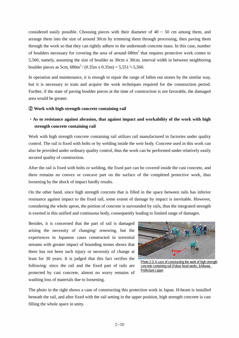
considered easily possible. Choosing pieces with their diameter of 40 ~ 50 cm among them, and
arrange them into the size of around 30cm by trimming them through processing, then paving them
through the work so that they can tightly adhere to the underneath concrete mass. In this case, number
of boulders necessary for covering the area of around 680m2 that requires protective work comes to
5,560, namely, assuming the size of boulder as 30cm x 30cm, interval width in between neighboring
boulder pieces as 5cm, 680m2 / (0.35m x 0.35m) = 5,551≒5,560.
In operation and maintenance, it is enough to repair the range of fallen out stones by the similar way,
but it is necessary to train and acquire the work techniques required for the construction period.
Further, if the state of paving boulder pieces at the time of construction is not favorable, the damaged
area would be greater.
② Work with high strength concrete containing rail
・As to resistance against abrasion, that against impact and workability of the work with high
strength concrete containing rail
Work with high strength concrete containing rail utilizes rail manufactured in factories under quality
control. The rail is fixed with bolts or by welding inside the weir body. Concrete used in this work can
also be provided under ordinary quality control, thus the work can be performed under relatively easily
secured quality of construction.
After the rail is fixed with bolts or welding, the fixed part can be covered inside the cast concrete, and
there remains no convex or concave part on the surface of the completed protective work, thus
loosening by the shock of impact hardly results.
On the other hand, since high strength concrete that is filled in the space between rails has inferior
resistance against impact to the fixed rail, some extent of damage by impact is inevitable. However,
considering the whole apron, the portion of concrete is surrounded by rails, thus the integrated strength
is exerted in this unified and continuous body, consequently leading to limited range of damages.
Besides, it is concerned that the part of rail is damaged
arising the necessity of changing/ renewing, but the
experiences in Japanese cases constructed in torrential
streams with greater impact of bounding stones shows that
there has not been such injury or necessity of change at
least for 30 years. It is judged that this fact verifies the
following: since the rail and the fixed part of rails are
protected by cast concrete, almost no worry remains of
washing loss of materials due to loosening.
The photo in the right shows a case of constructing this protection work in Japan. H-beam is installed
beneath the rail, and after fixed with the rail setting in the upper position, high strength concrete is cast
filling the whole space in unity.
Photo 2-3: A case of constructing the work of high strength concrete containing rail (Yokoe head works, Ishikawa Prefecture Japan
Flow
2-30

Thus, it is concluded that the work exerts enough strength as a protective work through the unification
with materials utilized, with high credibility of securing quality of construction.
In this context, the following 3 reasons imply
the fitness and effectiveness of the work of high
strength concrete containing rail to this river:
1. As regards discharge per unit width that
evaluate the energy during floods, the value of
Taklai River and that of Yokoe head works in
Japan that is the one of the cases where this work was applied roughly accords,
2. As regards environment where impact of the bounding stones exerted to the apron generates, Yokoe
head works have higher possibility of impact occurrence,
3. Under these conditions, no cracking or other serious injury has so far appeared on the apron at
Yokoe head works, thus the application of this method to the target river is considered relevant.
・As to procurement of materials to be used in protective work and O/M of the work with high
strength concrete containing rail
As to rail and H-beam, as they have not been manufactured in Bhutan, it is necessary to procure them
from India. In this regard, it is cost to procure and transport the rail and H-beam though, since both of
these materials do not require any particular specification, in other words they are generally dealt by
any steel producers, no problem arises to obtain them.
Quantity of each material to be disposed over an area of about 680m2 where surface protective work is
required comes to; rail: 17m x about 130 rail(equivalent to 40kg/m), H-beam: about 39.5m x 5rod
(equivalent to H x B =250 x 125).
Although a premise has been proposed that damaged parts over concrete filled in between rails should
pertinently be repaired and maintained, possibility of occurring some deformation on rail during
service period may remain, such damage or injury as requiring repair or renewal has not been given
for at least 30 years in the past experiences. Considering this fact, as to conceivable operation and
maintenance during service period, repairing damaged parts over concrete in between rails would be
needed. In the case of such repairing, fragile part around the damaged parts is removed and then fill
with new concrete, thus operation and maintenance at the site can readily be practiced.
(4) Apron protective work to be adopted
The selected two methods are evaluated in an integrated way based on the above-mentioned
comparative assessment, and the result of the evaluation is tabulated as follows, and it is finally
determined to adopt the work with high strength concrete containing rail.
Taklai River head works Yokoe head works
Design flood discharge 1,710m3/s 4,600m3/s
Length of weir About 60m 144m
Discharge per unit width 28.5m3/s/m 31.9m3/s/m
Height of weir 1.0m 7.4m
Table 2-19: Faciliy environment of Taklai River head works andYokoe H.W
2-31

Table 2-20: Table of comparison to determine the work to be adopted
Stone protection work High strength concrete containing rail
Since the strength of individual stone pieces is sufficient, excellent anti-impact and anti-abrasive effect can be expected, provided that adhesion between aligned stones and concrete mass beneath them is secured. However, unless construction work is properly carried out, function as a protective work that is exerted by unified mass with the apron can hardly be expected, emerging falling out of the paved stones that may be escalated to enlarged range of damages.
Quality of construction can readily be secured under this work, the strength is exerted as a protective work through the unification of the protected body and materilas utilized for protection with a high quality. Though damages to high strength concrete cast and filled in between rails are inevitable, rail and apron concrete can continuously be fixed and exert integrated strength, thus the damaged range is limited.
Resistance against impact and abrasion
○ ○ Since high level of construction techniques is required, actual performances with this method is few in Japan. Construction techniques should also be ensured and it is important in the case of applying this method in Bhutan, but construction quality is hardly secured because of lack of clear construction standard for this work.
Since rail that is produced in factories under quality control is used inside the weir where it is fastened with bolts or welded, and also concrete can be cated under quality control by contractor, therefore sustenance of construction quality control is relatively easy.
Readiness of construction quality control
△ ○ Materials can be obtained in and around of the site. At the initial construction stage, about 5,560 stones are required. ・Initial cost of constructing surface protective work (including materials and construction works) Target area:680m2 Stone material:5,560
3,900Nu/m2(wet masonry and processed works) 3,900Nu/m2×680m2=2,652,000Nu
2.7 million Nu / set
Such steel materials as rail and H-beam are procured from India. but since they are not materials that need special order, supply of these is easily available。 However, cost is highly incurred as compared with stone protection. ・Initial cost of constructing surface protective work(including materials and nstallation & construction) Target area: 680m2 Rail: 17m x about 130(equivalent to 40kg/m), H-steel: about 39.5m x 5(equivalent to H x B =250 x 125 ) 10,900,000 Nu(rail works including materials)
3,000,000 Nu(materials for rail fix and works )
13.9 million Nu / set
Procurement of materials
○ △ Even damages take place, procurement of repairing materials is easy. However, it is necessary to master and learn the construction techniques at the construction stage from Japanese technician. Also, if the state of paving stones at the construction stage is not proper, damage occurring later would be escalated and the range of requiring rehabilitation becomes larger. ・Estimated O/M cost (Contents of repair: chipping concrete and repair of stone protection)
4.6000 Nu / m2
Necessity of repairing damages on high strength concrete may arise. Because rail itself has high stiffness and it is fixed with bolts or by welding, necessity of replacement wouldn’t arise during the service period. In this regard, normal strength concrete is used for repair, the strength after repair becomes weaker than original design.
・Estimated O/M cost ( Contents of repair: chipping concrete and rehabilitation)
600 Nu / m2
Operation & maintenance
△ ○
Though this method is really excellent from material procurement point of view, apprehension arises from failure of security on the credibility of construction techniques and quality. If construction quality is defect, effect of surface protection may become weaker, leading to larger range of repair and damage goes beyond the possibility of rehabilitation. Although cost of the work is inexpensive, ensuring the effect as a protective work would be inferior.
Procurement of the materials is possible in India and repair of high strength concrete filling in between rails would be necessary as O/M during the service period. Though initial construction cost is more expensive than the stone protection, both credibility on the strength of the protective work and readiness of O/M after the construction are superior thereto.
Integrated evaluation
△ ○
(adopted)
2-32

(5) Protection work in other parts
As the overflowing part of upstream
of the head works thrusts 1m at
maximum from current level of
river-bed, impact of bounding stones
is inevitable. Since this part has
bending structure, installation of rail
method examined above is difficult to
apply. Protective work with
steel-board can be considered to
partially protect with such processed
steel material. However, application
of steel-board protection work has
risk of washout loss induced, so it
arise necessary to consider again the
installation.
Re-installation of steel-board is done by welding new iron sheet in a way to close the washed out part,
but the tight contact with the under lying concrete is not so easily fixed, and usually another method of
fixing such as fixing by bolts. But it is obvious that such maintenance is almost impossible for local
facility keepers, thus protective work by means of concrete structure has to be adopted so that local
staff can manage it.
Considering all that is mentioned above, it is designed that boulder concrete is constructed at the
upstream of the weir body so that the excavated part is filled to the same level as that of overflow with
a gradient to the upstream side. Applying this structure, impact of bounding matters does not directly
contact toward overflowing part of the weir body. Then, the overflowing part of the weir body is
designed to construct with high strength concrete in order to reduce the abrasion. Also, downstream
slope of the overflowing part is designed to have the gradient of 1 : 0.2 that is adopted in order to
make less damages given by rolling bounding stones. Furthermore, the angle is trimming with a
circle-arch to reduce the impact of damages.
In this concern, the refilled part by bolder concrete does not unify with wire body itself. Therefore,
even though this part was more or less damaged it does not influence the function of the weir itself. In
addition, because this part is made of boulder concrete, it can readily and cheaply be repaired
whenever necessity arises to repair, also effect of preventing scouring at the excavated part can be
expected.
Fig 2-10: Range of applying apron protective work
2-33

2-2-2-3. Design of head race
Water diverted from the integrated head works
is conveyed to the 1st siphon of H.L.C. part
main through the head race running along the
river. Out of the total length around 1,050m of
the head race, 510m remains as earth canal and
the rest 540m is the canal of rectangular section.
Also, gabion baskets have been laid at a part of
the river side along the head race.
In this design, water intake by the integrated
head works and the connection of the head race
with the head works are reviewed, thereby
designing the structure secure the safety for any fatal influence of abrasion by abnormal velocity and
sedimentation sand occurring during intake and floods. The result of hydraulic calculation with design
flood discharge at the section of head race(1,710m3/s)is illustrated in the following figure, in which
red colored line indicates water level.
From this result, it is clear that the water level crosses over around existing pipe culvert along the
existing head race below the water level. It follows that necessity arises from this result to protect
canal from such as sand and bounding stones washed down by floods in the section of 360m from
head works. By this reason, it is designed as a culvert structure accompanying with bed protecting
work. Also, if any gate facility is installed along this section, it cause an obstacle against flood flow.
Therefore any gate facility is not installed in this section so as not to prevent flood flow. In this
connection, as to the downstream side of this 360m section, the head race canal is designed as open
canal because the flood water level runs below the existing head race.
Fig 2-11: Disposition of existing head race and existing gabion revetment
Planned site of head works Existing pipes culvert
Designed section of culvert Designed section of open canal
(about 360m)
Fig 2-12; Vertical section of the river
2-34

(1) Structure of the part of culvert
The structure of the culvert body is designed as concrete considering readiness of local operation and
maintenance along with the basic principles. Inner cross section of the culvert is designed in
consideration with the construction ease of the concrete work and practicability of O/M as the
following: assuming H × B = 1.0m × 1.5m, verified with Manning’s formula, to ensure a
cross-sectional area of flow: 2.24m3/s.
In this concern, as the section of culvert
submerges under the water surface during floods
and risk of the damages by torrential flow or
abrasion may arise, it is designed to bury the
culvert body as far as possible. As a clue of
determining the depth of laying the culvert, the
bottom depth of the existing head race can be
made as a target elevation is roughly adjusted. And
the bottom line of the designed head race will be
connected to the H.L.C.
In this context, because of not installing any gate
at the integrated head works, the gradient of the
culvert is designed so that sand and gravel passing
bar-screen with the maximum diameter of around
30 ~40 mm do not deposit inside it.
Taking account of all mentioned above, canal gradient of the culvert section is designed at 1/150. The
resulting flow velocity to evolve and tractive particle size at this gradient are showed in the above
table, and the target particle size in this facility(30 ~40 mm)is not deposited in it. As to the
relationship between the crest elevation at the culvert and the bottom elevation of the existing head
race, it is shown in “2-2-3 Outline design drawing No. 3-1”.
a) Protective work at the river side
Embankment at the river side has risk of being influenced by abrasion, impact of bounding stones and
scouring.
Though it is difficult to quantitatively assess the influence of abrasion and bounding stones, influence
by these factors is considered limited as compared with the environment where the integrated head
works are planned because the vicinity of this facility is situated at the inner side of meandering at
river. Taking this into consideration, cross-section of concrete is designed at the minimum thickness
required for the river structures: more than 0.35m (sourced by Japanese Standard), but for the section
where velocity of the river flow is rapid, it is determined at the minimum thickness of the member for
apron described in “Design Standard of Head works”: 0.60m in order to reduce injuries at the surface
Designed intake
quantity Half of this quantity
Examined discharge 2.24m3/s 1.12m3/s
Water depth 0.607 m 0.371 m
Width of canal 1.500 m 1.500 m
Cross-sectional flow area
0.910 m2 0.556 m2
Hydraulic radius 0.335 m 0.248 m
Roughness coefficient 0.016 0.016
Canal gradient 1/150 1/150
Evolving flow velocity 2.46 m/s 2.02 m/s
Tractive particle diameter
About300 mm About 200 mm
Target particle diameter
30 ~40 mm 30 ~40 mm
Assessment result OK OK
Table 2-21: Tractive particle size at each level of discharge
Moving particle size (m) : d = Vc 2 / 20 where Vc (m/s) : marginal flow velocity to move
2-35

of wall that receives impact of stream flow. Similarly, to prevent scouring, it is designed to install
embedded foundation of 1m thick beneath the wall at the river side and, furthermore, to install bed
protection block for the flow velocity. The evolving flow velocity of the culvert section is calculated as
shown in the table below derived from hydrological calculations for the design flood discharge. The
dimensions of this block are determined referring to the afore-mentioned “2-2-2-2-5 Examination of
bed protection”.
The bed protection work applied to the culvert section is concrete block. In this connection, the
ranging about 290~360m at the section of head race as shown in the table is located
at the shallow position compared
with the flood water level, and the
flow area around this section is
culculated about 10% of the total
flow section. Under these
conditions, the mean flow velocity
around this section is predicted at
about less than half (3m/s)of the
mean velocity ( 6m/s ) .Taking
account of the flow velocity to be applied to the gabion layer as bed protection work ranges about 5 ~
4m/s, gabion work is designed to apply to the section between about 290~360m.
b) Preventing measures against scouring at the side of rock mass
The mountain side of the culvert section consists of compacted sand~ gravelly river terrace that is not
considered fully stable because it has been formed by sedimentation. Adopting such slope protective
work as concrete lining is concerned to secure a long-term stabilization of slope surface, but actually
the canal is planned to construct with a culvert structure, so the water-flow at culvert can be
guaranteed even if some extent of collapse took place over the slope.
By this reason, necessity of slope protection does not need. In addition, the river terrace at the right
bank where head race runs is located inside of meandering part of the river, the extent of collapse over
the slope is considered limited in a sporadic occurrence. In this connection, excavation of the
mountain becomes necessary in the course of the construction work, it is designed to arrange the
excavation gradient at 1:1.0 that gives stability over the sand/ gravelly mountain. At the same time,
since the section of culvert is submerged under flood water, gabion layers are to be laid over the range
of ground excavation up to the level of the top of the culvert- head race for preventing scouring.
c) Standard section of the culvert section
From the result of above-cited examination, the standard cross section of the culvert is given as the
following figure:
Evolving flow velocity in the culvert section and foot protection block to be applied
Applying section Section up to about160m from head
works
Section between 160~290m
Section between 290~360m
Examined discharge 1,710 m3/s 1,710 m3/s 1,710 m3/s
Flood level WL 303.8 ~303.4m WL 303.4 ~300.9m
WL 300.9 ~299.1m
Culvert crest elevation EL 300.5 ~299.5 m EL 299.5 ~298.6 m
EL 298.6 ~298.2 m
Water depth 3.3 ~ 3.9m 3.9 ~ 2.3m 3.9 ~ 0.9m
Section flow velocity 8 ~7 m/s 7 m/s ~ 5 m/s 6 m/s (3m/s)
Block to be applied 8 ton Block (P.V:9.5m/s)
3 ton Block (P.V:7.8m/s)
Gabion baskets(P.V:5.0m/s)
Table 2-22: Hydraulic calibration values & examination of applicable bed protection block
2-36
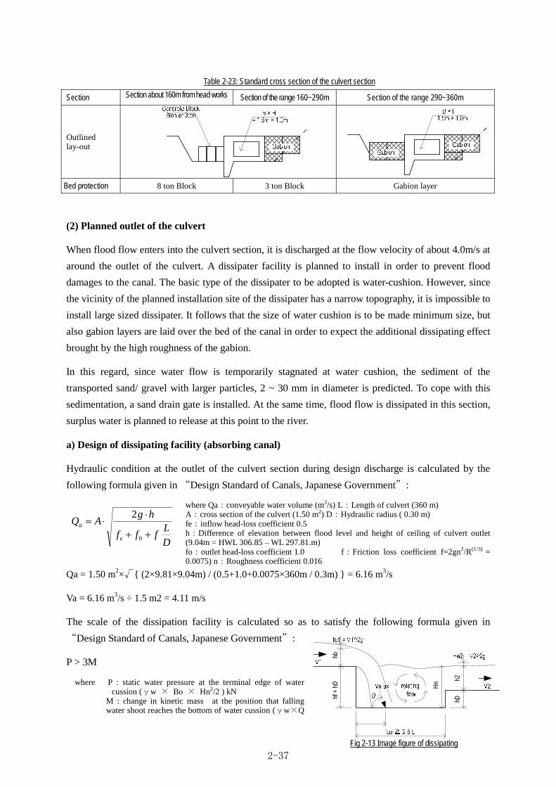
Section Section about 160m from head works Section of the range 160~290m Section of the range 290~360m
Outlined lay-out
Bed protection 8 ton Block 3 ton Block Gabion layer
(2) Planned outlet of the culvert
When flood flow enters into the culvert section, it is discharged at the flow velocity of about 4.0m/s at
around the outlet of the culvert. A dissipater facility is planned to install in order to prevent flood
damages to the canal. The basic type of the dissipater to be adopted is water-cushion. However, since
the vicinity of the planned installation site of the dissipater has a narrow topography, it is impossible to
install large sized dissipater. It follows that the size of water cushion is to be made minimum size, but
also gabion layers are laid over the bed of the canal in order to expect the additional dissipating effect
brought by the high roughness of the gabion.
In this regard, since water flow is temporarily stagnated at water cushion, the sediment of the
transported sand/ gravel with larger particles, 2 ~ 30 mm in diameter is predicted. To cope with this
sedimentation, a sand drain gate is installed. At the same time, flood flow is dissipated in this section,
surplus water is planned to release at this point to the river.
a) Design of dissipating facility (absorbing canal)
Hydraulic condition at the outlet of the culvert section during design discharge is calculated by the
following formula given in “Design Standard of Canals, Japanese Government”:
where Qa:conveyable water volume (m3/s) L:Length of culvert (360 m) A:cross section of the culvert (1.50 m2) D:Hydraulic radius ( 0.30 m) fe:inflow head-loss coefficient 0.5 h:Difference of elevation between flood level and height of ceiling of culvert outlet (9.04m = HWL 306.85 – WL 297.81.m) fo:outlet head-loss coefficient 1.0 f:Friction loss coefficient f=2gn2/R(1/3) = 0.0075) n:Roughness coefficient 0.016
Qa = 1.50 m2×√{ (2×9.81×9.04m) / (0.5+1.0+0.0075×360m / 0.3m) } = 6.16 m3/s
Va = 6.16 m3/s ÷ 1.5 m2 = 4.11 m/s
The scale of the dissipation facility is calculated so as to satisfy the following formula given in
“Design Standard of Canals, Japanese Government”:
P > 3M
where P : static water pressure at the terminal edge of water cussion (γw × Bo × Hn2/2 ) kN
M : change in kinetic mass at the position that falling water shoot reaches the bottom of water cussion (γw×Q
DL
fff
hgAQ
e
a
0
2
hbhf
+ h
D Hn
hDh2
Table 2-23: Standard cross section of the culvert section
Fig 2-13 Image figure of dissipating
2-37

×Vm/g) kN γw : unit volumetric weight of water: 9.8 kN/m3 Q : discharge (6.16 m3/s) Hn : wager depth at terminal edge of water cussion ( hD + h2 + V22/2g) m Vm : flow velocity at the moment that falling water shoot reaches the bottom of water cussion Vm = √( 2g ×(He1 + hf +hD + hb) m/s
Under the given condition, in the examination by the above
formula, about 3m is required for height of drop(hf + hD)
while around 6m is needed for the width of canal (Bo)and even
as long as about 10m is necessary for its length in order to obtain
the dissipation effect (refer to case 1 in the right). Nevertheless,
topography observed in the vicinity of the planned outlet of the
culvert section where the dissipater is to be installed is
characterized with neighboring with slope of mountain in the
right side while in the left side the elevation difference between
this site and the river-bed is only about 3m (refer to the overall
design map). Hence, the above calculated scale would result in
almost entire excavation of the planned site, an anxiety arises
from this result that the installation of the calculated scale
dissipater on the contrary may disturb the stability of the ground
of the site.
Accordingly, another case is assumed in which the range of absorbing canal is limited within the area
of dropping water, designing a scale of the depth of 1.5m, the width of 3.0m and the length of 7.5m
deriving from the scale of the culvert and the topographic condition of the site, then P = 10.4 kN、M =
5.1 kN is obtained(refer to Case2 in the above table). Under this assumption, though P ≒ 2M < 3M,
energy dissipating effect can be obtained against the annual-mean scale of flood, and as measures for
the occasion of occurring the scale of the design discharge. So it is designed to lay gabion layers inside
the downstream canal so as to structurally satisfy the dissipating effect with this combination of
dissipater and gabion.
The following figure shows the cross section of the dissipating facility.
Fig 2-14: Cross section of the dissipater
1.50
1.00 1.50
1.70
1.00
1.00
Case1 Case2
Q (m3/s) 6.16 6.16
V1 (m/s) 4.11 4.11
He (m) 1.86 1.86
Δh1 (m) 3.00 1.50
h2 (m) 0.71 0.71
Δh2 (m) 1.50 1.50
V2 (m/s) 2.90 2.90
Vm (m/s) 9.77 8.12
Hn (m) 2.64 2.64
L (m) 3.90 2.82
9.75 7.06
10.00 7.50
B (m) 6.00 3.00
P (kN) 20.85 10.43
M (kN) 6.14 5.10
3M (kN) 18.41 15.31
Lr=2.5L (m)
Table 2-24: Examination of the scale of dissipater
2-38

b) Structure of spillway for surplus water
The spillway for the surplus wateris designed to construct at the downstream of the dissipating facility,
for which an examination is made deeming the difference between inflow quantities into head race
during floods: 6.16m3/s and design inatake quantity: 2.24m3/s, namely 3.92m3/s as surplus water.
The structure of the spillway is designed in a way that cut-out part is worked at the flank wall from
which surplus water is evacuated into the original stream. For determining its size, water depths are
calculated at the above-cited two levels of discharges, deeming the difference of these two depths as
the depth of overflow on the spillway, for calculating the length required for releasing the target
surplus quantity: 3.92m3/s, namely the length of the spillway. In this process, the length of the spillway
is derived from Forchheimer’s formula.
ho + h2Q = 2/3 × μ × √2g L × (
2 ) 3/2
3Q
ho + h1L = 2× μ × √2g × (
2 ) 3/2
where Q : (surplus)discharge (3.92 m3/s) μ : overflow coefficient 0.644 g : gravitational acceleration 9.8m/s2 L : length of overflowing apron (m) γw : unit volumetric weight of water 9.8 kN/m3 h1 : overflow depth at upstream side : 0.468 m = 1.468 m (depth of upstream side) – 1.00m (height of flank wall) h0 : overflow depth at downstream side : 0m (making 0 at the lower edge of the spillway)
3 × 3.92 0.468 +0 L =
2× 0.644 × √19.62 × (2
) 3/2 = 18.21m
As a result, the length of the spillway is determined at 18.21m or longer, to be constructed in the
section shown below:
(4) Structure of the section of existing open channel
Out of the section of open channel, that of rectangular section 370m long has longitudinal slope of
about 1/140, lined with concrete of a thickness of around 10cm. Because evolving flow velocity inside
the channel exceeds allowable velocity of concrete lined canal of the lining thickness of less than
10cm, namely 1.5m/s calculated by Manning’s formula (based on the Design Standard of Canal Works,
Fig 2-15. Cross section of spillway
2-39

Japanese Government), it is designed to reinforce it with 20cm thick concrete without re-bar. In this
case of this thickness of concrete, allowable velocity comes to 3.0m/s. The following shows the result
of this hydraulic calculation of the existing canal.
(5) Plan of sedimentation basin
Since any gate facility is not planned to install for preventing floods in the vicinity of the head works
in this planned head race of the target facilities, sand/ gravel flowing from the head works flows down
in the head race. Though it is designed with a canal gradient that does not allow sand sedimentation in
the head race, it is required to eliminate flowing down sand /gravel before flowing into the H.L.C.
For this purpose, in order to evacuate sand/ gravel with the diameter of 0.3mm or larger that is harmful
to the irrigation as described in the "Design Standard of the Head Works, Japanese Government", a
sedimentation basin is to be installed around the upstream of No.1 siphon where land space for
constructing the planned facility can be procured.
The design of the sedimentation basin is based on the Design Standard of the Head Works, Japanese
Government.
a) Gradient of the sedimentation basin
The gradient of the bottom of the sedimentation basin is
planned referring to the Froude number for “sand drain
channel” described in “Hydrological Design of River
Structures, Japanese Government”, marking at around Fr = 2.5.
Taking the connection to the existing canal into consideration,
the Froude number is calculated under the gradient of I = 1/35
assuming uniform flow. It gives Fr = 2.3 as shown in the below
table, and this value is to be adopted.
Existing section After reinforcing it
Examined discharge 2.24m3/s 2.24m3/s
Water depth 0.25 m 0.27 m
Width of the canal 4.50 m 4.10 m
C.S.* area of flow 1.138 m2 1.104 m2
Wetted perimeter 5.006m 4.639 m
Hydraulic mean depth 0.227 m 0.238m
Roughness coefficient 0.016 0.016 m
Canal gradient 1/140 1/140
Flow velocity 1.97 m/s 2.03 m/s
Allowable flow velocity 1.5m/s 3.0m/s
Judgment NG OK
* C.S.: cross-sectional
Existing section Discharge of sand draining 2.24m3/s Water depth 0.080 m
Width of the canal 7.000 m C.S.* area of flow 0.871 m2 Wetted perimeter 7.249m Hydraulic mean depth 0.120 m Roughness coefficient 0.016 Canal gradient 1/35 Width of the canal 2.57 m/s Fr 2.3 * C.S.: cross-sectional
Fig 2-16: Image of repair of rectangular sectioned open channel in headrace
Table 2-25: Hydraulic calculation of the existing rectangular sectioned canal
Table 2-26: Calculation of gradient of sedimentation basin
2-40
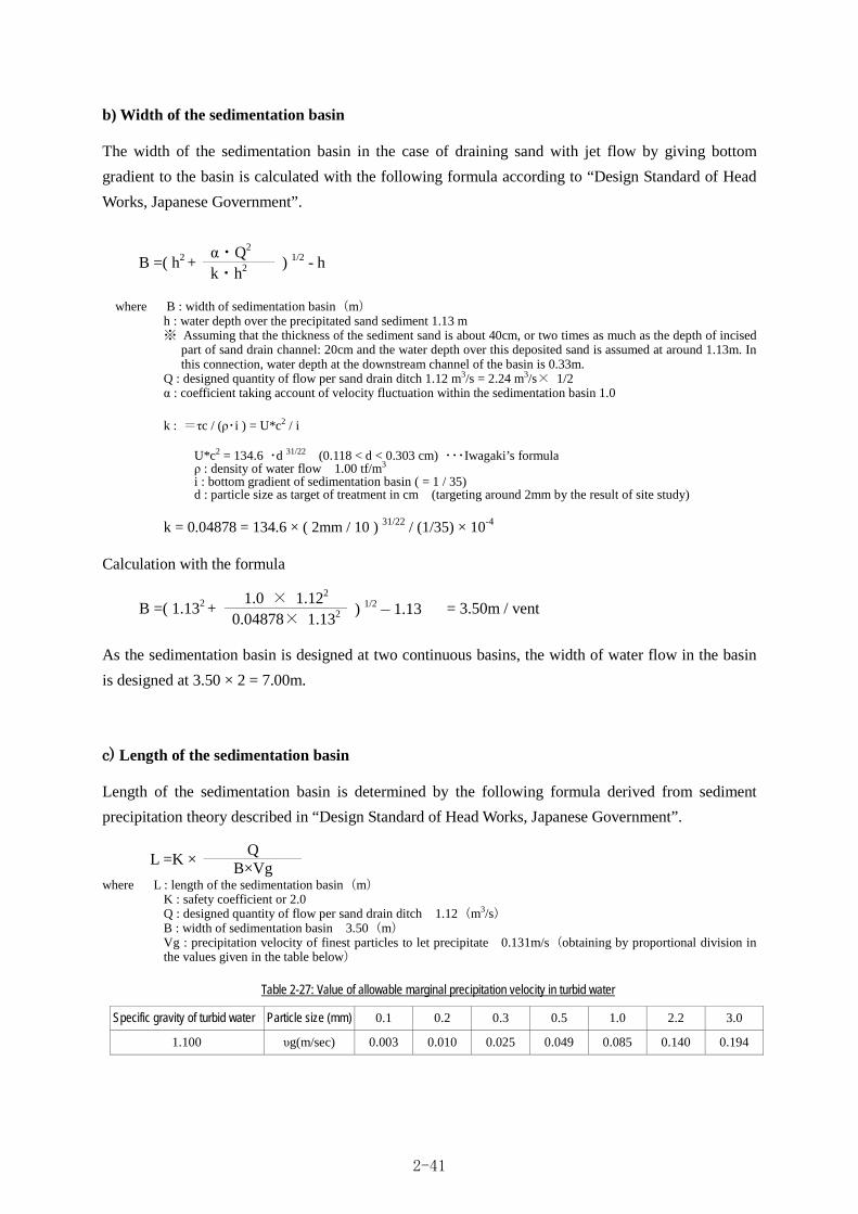
b) Width of the sedimentation basin
The width of the sedimentation basin in the case of draining sand with jet flow by giving bottom
gradient to the basin is calculated with the following formula according to “Design Standard of Head
Works, Japanese Government”.
where B : width of sedimentation basin(m) h : water depth over the precipitated sand sediment 1.13 m ※ Assuming that the thickness of the sediment sand is about 40cm, or two times as much as the depth of incised
part of sand drain channel: 20cm and the water depth over this deposited sand is assumed at around 1.13m. In this connection, water depth at the downstream channel of the basin is 0.33m.
Q : designed quantity of flow per sand drain ditch 1.12 m3/s = 2.24 m3/s× 1/2 α : coefficient taking account of velocity fluctuation within the sedimentation basin 1.0
k : =τc / (ρ・i ) = U*c2 / i
U*c2 = 134.6 ・d 31/22 (0.118 < d < 0.303 cm) ・・・Iwagaki’s formula ρ : density of water flow 1.00 tf/m3 i : bottom gradient of sedimentation basin ( = 1 / 35) d : particle size as target of treatment in cm (targeting around 2mm by the result of site study)
k = 0.04878 = 134.6 × ( 2mm / 10 ) 31/22 / (1/35) × 10-4
Calculation with the formula
1.0 × 1.122 B =( 1.132 +
0.04878× 1.132 ) 1/2 – 1.13 = 3.50m / vent
As the sedimentation basin is designed at two continuous basins, the width of water flow in the basin
is designed at 3.50 × 2 = 7.00m.
c) Length of the sedimentation basin
Length of the sedimentation basin is determined by the following formula derived from sediment
precipitation theory described in “Design Standard of Head Works, Japanese Government”.
Q L =K ×
B×Vg where L : length of the sedimentation basin(m)
K : safety coefficient or 2.0 Q : designed quantity of flow per sand drain ditch 1.12(m3/s) B : width of sedimentation basin 3.50(m) Vg : precipitation velocity of finest particles to let precipitate 0.131m/s(obtaining by proportional division in the values given in the table below)
Table 2-27: Value of allowable marginal precipitation velocity in turbid water
Specific gravity of turbid water Particle size (mm) 0.1 0.2 0.3 0.5 1.0 2.2 3.0
1.100 υg(m/sec) 0.003 0.010 0.025 0.049 0.085 0.140 0.194
α・Q2 B =( h2 +
k・h2 ) 1/2 - h
2-41
1.12 L = 2.00 ×
3.50×0.131 = 4.9m → 5.0m
As a result of above calculation, the length of the sedimentation basin is designed at 5.00m.
2-2-2-4. Reinforcement of the existing gabion wall
The existing protection work on the banks of head race along the Taklai River consists of slope
protection by gabion. As this protection has height of over 5m and a steep piling-up gradient of 1:
0.2, this structure is concerned to easy collapse by outer force. In the occasion of flood disaster in
2010 gabion laid as wide as about 500m was washed away by flood water and also upstream part of
head race was collapsed, eventually leading the failure to Taklai Irrigation Area for longer than a half
year.
At present, damaged gabion wall has been rehabilitated to maintain the original configuration. taking
this into consideration, design is made into consideration of the following with a premise that gabion
is utilized in the plan as it is currently placed.
(1) Method of reinforcing the existing gabion wall
Since back side of the existing gabion wall is an independent state of stability, earth pressure of back
side earth does not exert to gabion. Hence, concerned outer forces possibly exerting to gabion is from
the river side include flood pressure etc. Judging from this state, as a strategy of design for protection,
pertinent and economical design will be resulted from the use of the existing gabion work as it is and
additional protection work in front of the existing gabion layers to increase resistance against flood
flow and impact by bounding stones. In the table below is shown the some works to make it tolerant
against outer force, but from the standpoints of reinforcing effect and ease of construction, covering by
concrete retaining wall is considered appropriate.
2-42

Table 2-28: Methods of reinforcing the existing gabion protection
Protective work by protection with huge sized stones
Protective work by concrete retaining wall Protective work by concrete blocks
Structure
Placing huge stons of the required size in front of the existing gabion. Material available at the site is utilized, but large amount of material is necessary for this work.
Covered by concrete retaining wall that has suitable weight and thickness at the front side of on the existing gabion layers.
Concrete blocks with required weight are piled at the front of the existing gabion layers.
Designed flow velocity 5m/s~6m/s ditto ditto
Required weight or size
Diameter: 2.5m~3.0m(5t~8t) (slope of stone pile 1:1.5)
Thickness of materials: thicker than 35cm (thickness is determined by stability calculation)
Heavier than 3t~4t
Reinforcing effect
Because huge stones have high strength, high reinforcing effect can be obtained provided that stone piling is properly worked.
Since this is a common work for river bank protection, reinforcing effect is securely expected. In addition, because it has considerable thickness of the materials, it also has resistance against impact of small bounding stones.
This is also an ordinary type of protection. It is often adopted in the case of expecting bed protection and effect of dissipating waves. This method is considered inferior to that shown in the left column because of longer resistant surface for the water flow.
Ease of construction work
While hoisting weight reaches about 5t~8t, necessary radius of hoisting work comes to around 10m. Therefore, such heavy machinery as crawler crane is required for this work. It is practically difficult to pile up different shaped stones, also the work accompanies with danger. Since huge stones satisfying the necessary specification is not abundantly found in the site, it may be required to transport them from other places. Not recommendable due to not only its inferiority from ease of work, but also the limited usage of huge sized crane to revetment work is arisen economic waste.
Since the work utilized cast-in-place concrete, it has an excellent ease of construction. Economic concern may arise, because the section of the work is lengthy.
Though this work is similar to the construction of concrete structures, it has a different process that blocks are cast in manufacturing yard then piled up with a crane. From design concept point of view, this method has a similarity to the concrete retaining wall mentioned in the left, and reinforcing effect is also similar thereto, but it has inferior ease of construction because of additional necessity of piling up.
Appraisal
Though the work requires a large sized crane, its transportation to the site is difficult, and its usage is limited, resulting in uneconomical method. Collection of enough materials of huge stones is also difficult.
(×)
This method has high ease of construction and also high protective effect. As to economic issue, the quantity of concrete will be economized by examining the size of protection.
(○)
Though similar evaluation is made to the concrete retaining wall mentioned in the left, this method is considered to have inferior ease of construction because of additional requirement of work for piling up.
(△)
(2) Range of applying protection measures to the existing gabion wall
The range of protecting concrete retaining wall is planned by hydrological calculation in which
river-bed shape is considered. The length of the range towards the downstream side of the river is
2-43

determined equal to the range of the existing gabion layers adjacent to the head race: 410m. As regards
the height of the reinforced concrete retaining wall is determined taking account of increment of water
level caused by the meandering flow of the river added to the water depth which is calculated for the
designed flood discharge.
From the result of hydrological calculation at the typical section of the existing gabion work, water
level is derived as WL295.0~292.0m. Adding 0.6 m which is the height increase of the water level the
meandered part to this elevation, the height of water level reach HWL 295.6~292.6m.
Table 2-29: Calculation of water level increase at meandered part of river stream
Formula for the calculation Result of calculation
B : 80m
V : 5m/s
rc : 360m
Δh0: 0.65 m
Δh0=B・V2/g/ rc Δh1=Δh0/2
where Δh1 :increment of water level by meandering (m) B :Mean width of water surface in the mending section, Obtained from plane figure (80m) V :Mean flow velocity in the vicinity of meandering part Obtained from hydrological calculation (5.3 m/s) rc :Meandering radius Obtained from plane figure (350 m) g :9.81m/s2
In this calculation, the range of rc<10 is adopted in consideration. Δh1: 0.56m → 0.6m
As a result, the water depth around the site is calculated at 2.6m as obtained from the ground level of
the existing gabion wall which is EL293.0 ~ 290.0m, adding as free board to this in consideration of
the influence by surface wave etc, therefore the height of the concrete retaining wall is determined at
3m.
(3) Examination on bed protection for the wall
From the result of the following examination, the depth of scouring likely to evolve is estimated at
around 2m. Since flow velocity of the examined section is estimated at around 5m/s, gabion layer is
planned to install within the depth of 2m as embedded foundation work, and it is also planned to re-fill
at the excavated range with gabion during the construction of concrete retaining wall.
According to “Planning and Design of Revetment / Groin”, maximum depth of scouring is estimated
by the water depth for the occurrence of mean annual maximum discharge, in which the relationship in
some studied cases is illustrated in the figure below. Although this is not necessary of relation between
Japanese example cases and Taklai River, because these are a different stream flow environment, it is
merely used as a rough standard to estimate the necessary range of embedded foundation
Fig 2-17: Water level at design flood discharge and water depth around gabion wall
2-44
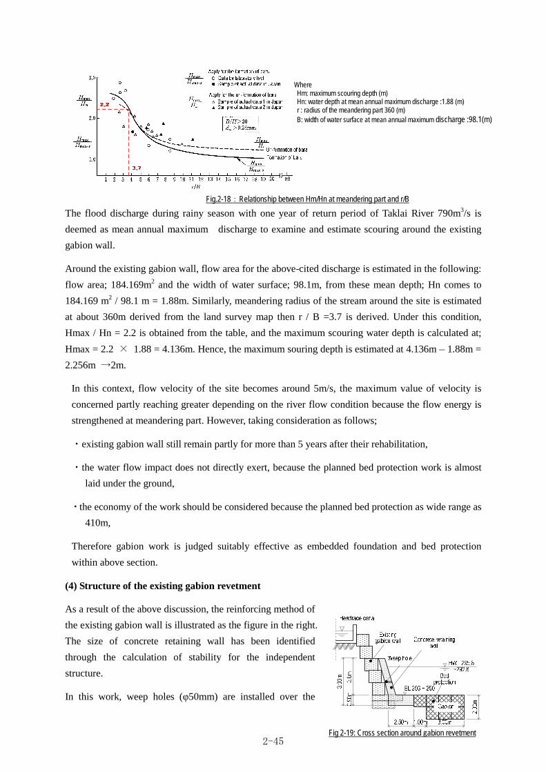
The flood discharge during rainy season with one year of return period of Taklai River 790m3/s is
deemed as mean annual maximum discharge to examine and estimate scouring around the existing
gabion wall.
Around the existing gabion wall, flow area for the above-cited discharge is estimated in the following:
flow area; 184.169m2 and the width of water surface; 98.1m, from these mean depth; Hn comes to
184.169 m2 / 98.1 m = 1.88m. Similarly, meandering radius of the stream around the site is estimated
at about 360m derived from the land survey map then r / B =3.7 is derived. Under this condition,
Hmax / Hn = 2.2 is obtained from the table, and the maximum scouring water depth is calculated at;
Hmax = 2.2 × 1.88 = 4.136m. Hence, the maximum souring depth is estimated at 4.136m – 1.88m =
2.256m →2m.
In this context, flow velocity of the site becomes around 5m/s, the maximum value of velocity is
concerned partly reaching greater depending on the river flow condition because the flow energy is
strengthened at meandering part. However, taking consideration as follows;
・existing gabion wall still remain partly for more than 5 years after their rehabilitation,
・the water flow impact does not directly exert, because the planned bed protection work is almost
laid under the ground,
・the economy of the work should be considered because the planned bed protection as wide range as
410m,
Therefore gabion work is judged suitably effective as embedded foundation and bed protection
within above section.
(4) Structure of the existing gabion revetment
As a result of the above discussion, the reinforcing method of
the existing gabion wall is illustrated as the figure in the right.
The size of concrete retaining wall has been identified
through the calculation of stability for the independent
structure.
In this work, weep holes (φ50mm) are installed over the
Fig.2-18:Relationship between Hm/Hn at meandering part and r/B
Where Hm: maximum scouring depth (m) Hn: water depth at mean annual maximum discharge :1.88 (m) r : radius of the meandering part 360 (m) B: width of water surface at mean annual maximum discharge :98.1(m)
Fig 2-19: Cross section around gabion revetment 2-45

retaining wall to drain the rain water.
・Calculation Condition
The calculation section show in right figure
Concrete:23kN/m3、Behind water depth:2m、Internal friction of soil:φ35°、Wet unit weight:
19kN/m3(Submerged unit weight:20kN/m3)
・Result of calculation
For the overturning -0.258m≦ 0.417m (capacity.):OK
For the sliding 1.50≦1.5 (capacity.):OK
2-2-2-5. Protection dike at the downstream of Taklai River
At the point of the downstream of the river, about 2 km from the planned site of the integrated head
works, a natural diversion of flow line was formed at the right bank side during a flood that gave
damage of sweeping away to a part of farmland at downstream. To prevent the repeated damages, the
Bhutan side provided protection works by gabion
around beginning of inflow part, but all the work was
washed away by the flood occurred in 2010, thus this
section is currently left without any protection works.
To cope with such damage, a dike is planned to
construct for protection of farmland. In this plan, the
maximum height of dike is same level as the river
terrace at the existing upstream and downstream.
Fig 2-21: Location of the planned embankment
Fig 2-20 : Section for calculation
2-46
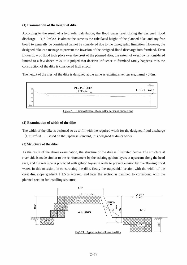
(1) Examination of the height of dike
According to the result of a hydraulic calculation, the flood water level during the designed flood
discharge (1,710m3/s)is almost the same as the calculated height of the planned dike, and any free
board to generally be considered cannot be considered due to the topographic limitation. However, the
designed dike can manage to prevent the invasion of the designed flood discharge into farmland. Even
if overflow of flood took place over the crest of the planned dike, the extent of overflow is considered
limited to a few dozen m3/s, it is judged that decisive influence to farmland rarely happens, thus the
construction of the dike is considered high effect.
The height of the crest of the dike is designed at the same as existing river terrace, namely 3.0m.
(2) Examination of width of the dike
The width of the dike is designed so as to fill with the required width for the designed flood discharge
(1,710m3/s). Based on the Japanese standard, it is designed at 4m or wider.
(3) Structure of the dike
As the result of the above examination, the structure of the dike is illustrated below. The structure at
river side is made similar to the reinforcement by the existing gabion layers at upstream along the head
race, and the rear side is protected with gabion layers in order to prevent erosion by overflowing flood
water. In this occasion, in constructing the dike, firstly the trapezoidal section with the width of the
crest 4m, slope gradient 1:1.5 is worked, and later the section is trimmed to correspond with the
planned section for installing structure.
Fig 2-22: :Flood water level at around the section of planned Dike
Fig 2-23:Typical section of Protection Dike
2-47

2-2-2-6. Existing main canal and related facilities
(1) Rehabilitation for the flow capacity of the Existing main canal and related facilities
The existing main canal and related facilities can almost flow the design intake discharge: 2.24m3/s
without any change in its section, however, there is a section in short of free board of the canal around
the outlet of the first siphon. It is therefore designed that this section is raised up the wall. In addition,
by the reason that not only free board of link canal is insufficient, but also flow velocity exceeds the
allowable flow velocity: 1.5m/s (based on the “Design Standard of Canal Work, Japanese
Government”), it is necessary to reinforce the canal bottom.
The discharge of the L.L.C. is 0.92m3/s which is less than half that of H.L.C. However, L.L.C has
almost the same section area as H.L.C. Therefore it is specified that L.L.C has sufficient capacity of
conveyance by the examination of H.L.C. on its flow capacity only.
Table 2-30: Evaluation and treatment of canal flow capacity Name of canal Shape of canal section Evaluation Method of treatment to improve flow Downstream side of first siphon at H.L.C.
Rectangle section (wet masonry)
Free board is not sufficient Actual Hfb =0.12 m < 0.15m = Fbr
The existing wall needs to rise up. 10cm more or less is added to existing wall in free board.
H.L.C Trapezoidal section(lined with wet masonry)゙
Possible to use the existing section as it is Treatment is not necessary
Link canal Trapezoidal section(wet masonry)
Free board is not sufficient Actual Hfb =-0.09 m < 0.14m = Fbr
The bottom gradient of the link canal changes at every vertical drop. Therefore, the required height of wall is examined for each section divided by vertical drop. Also, as to canal gradient, it is individually examined by section. Here, only the notice is made on the necessity of raising up wall for the canal, as well of the reinforcement of the canal bottom for the section where flow velocity exceeds 1.5m/s.
The methods of reinforcing or of rehabilitating each of main canals are shown in “Outline Design Drawing
No.13”.
(2) Additional repair and rehabilitation of related facilities and canal section
As regards related structures, breakage and leakage of wall of wet masonry canals, stones dropped down
inside canals, operational disorder / degradation of water-stop of gates, exposure and cracking of siphon
tubes are issues to be coped with. For the broken parts it is planned to repair and replace. However some
related facilities is inevitable to receive the damage by strong force such as dropped stone or abrasion.
Therefore, as the basic policy for the rehabilitation and improvement for these structures, the concrete
works is adopted. Because the possibility of the continuous maintenance and suitable durability is required
for these structures
Also, at confluence between L.L.C and Link canal, gabion layer for dissipation is planned to install and be
closed by concrete retaining wall. In addition, a gate is designed to install to control inflow water from the
river.
Individual methods of repair and rehabilitation are shown in detail in “Outline Design Figure No.13 and
No.15”. The following pictures show the state of damages on the main canal and related structures.
2-48

Table 2-31: Evaluation with visual observation on canals and related structures
Name of canal Item (parts, place) Quantity Photo for reference Countermeasures
The part requiring rehabilitation at the damaged wall of the canal
L=115m
Wet masonry is rehabilitated for the recovery t.
The section requiring prevention of dropping stones from the mountain lying behind canal
L=200m
Concrete cover with 20cm thick is installed at the upper part of the canal
The road bridge constructed over the canal is required repair
2 sites
It is renewed into a concrete bridge of the dimension: B×L = 4.0m ×3.9m
The part requiring repair for the leakage from the bottom of the canal
2 sites
It is repaired by plastering mortar inside the canal, also lining concrete outside of the canal.
Damaged gates 8 gates
Gates are renewed.
The site where newly constructed check gate is required.
1site
A gate is installed.
The site where new construction of diversion gate is required.
1 site
The gate is exchanged.
The part requiring protection for the exposed siphon pipe L=45m
The exposed part of the siphon is covered by concrete.
High Level Canal
The part requiring repair for the broken siphon pipe 1site
Cracking is repaired with concrete lining.
Damage of masonry wall
Fallen stone
Mountain side
Exposed re-bar
Leaking water from canal
loss of spindle
Loss of spindle
Exposed siphon
2-49
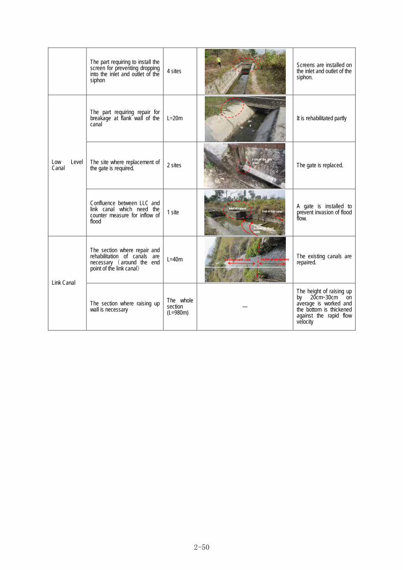
The part requiring to install the screen for preventing dropping into the inlet and outlet of the siphon
4 sites
Screens are installed on the inlet and outlet of the siphon.
The part requiring repair for breakage at flank wall of the canal
L=20m
It is rehabilitated partly
The site where replacement of the gate is required. 2 sites
The gate is replaced. Low Level Canal
Confluence between LLC and link canal which need the counter measure for inflow of flood
1 site
A gate is installed to prevent invasion of flood flow.
The section where repair and rehabilitation of canals are necessary( around the end point of the link canal)
L=40m
The existing canals are repaired.
Link Canal
The section where raising up wall is necessary
The whole section (L=980m)
---
The height of raising up by 20cm~30cm on average is worked and the bottom is thickened against the rapid flow velocity
Loss of the gate guide
End of link canal Inlet of siphon
In-flow of flood water
Section of earth canal Section of wet masonry
2-50

2-2-3 Outline design drawing
Drawing List
DRW No. Drawing Name Pcs
No.1 General Map of the Taklai Irrigation System 1
No.2 General Plan of Taklai River 2
No.3 Longitudinal Profile of Taklai River 2
No.4 General Plan of Head Works 1
No.5 Longitudinal Section of Head Works 3
No.6 Cross Section of Outlet of Box Culvert 2
No.7 General Plan and New Open Canal 4
No.8 New Open Canal 2 and Sedimentation Basin 3
No.9 Longitudinal Profile of Candidate Site for Protection Dike 1
No.10 Longitudinal Profile of Link Canal 2
No.11 Cross Section of Link Canal 4
No.12 Longitudinal Profile of High Level Canal 7
No.13 Rehabilitation Plan of High Level Canal 3
No.14 Longitudinal Profile of Low Level Canal 4
No.15 Improvement Plan of Existing Confluence 1
Total 40
2-51

00.5
12
Kilo
met
ers
Kal
i Riv
er
Mao River
Taklai
Rive
r
00
Ta
kla
i Irr
iga
tion
Sys
tem
in S
arp
ang
Dis
tric
t T
he
Pro
ject
for
imp
rove
me
nt o
f
Ge
nera
l Ma
p o
f th
e T
akl
ai I
rrig
atio
n S
ysyt
em
N
Flow
Flow
Hea
d w
orks
Hea
drac
e ca
nal
High
leve
l can
al1s
t Sip
hon
2nd
Siph
on
C.G
2C
.G1
C.G
3
C.G
4C
.G53r
d Si
phon
C.G
6C
.G7
C.G
8
Siph
on to
Hill
C.G
9
C.G
11
C.G
12
C.G
13
Siph
on
Low
leve
l can
al
Earth
can
al
Low
leve
l can
al
Link
can
al
Exi
stin
g R
oad
s
Riv
er
L= 0
.98
km
L= 6
.2 k
m
L= 1
.04
km
L= 2
. 9km
C.G
1C
.G2
C.G
7
C.G
3C
.G4
C.G
5C
.G6
C.G
10
L= 2
.2km
Prot
ectio
n D
ike
Gen
eral
Map
of
the
Tak
lai I
rrig
atio
n S
ysyt
em
No.1
2-52

BH 1
BH 2
BH 3
BH 4
TBM
1
305
310
310
315
300
310315
300
305
305
TBM
2
N
RL'
RL
SC.8
SC.3
SC.2
SC.1
SC.3
SC.2
SC.8
SC.9
SC.7
SC.7
SC.6
SC.5
SC.4
SC.6
SC.5
SC.4
SC.9
SC.1
0
03-1Ta
klai
Irrig
atio
n Sy
stem
in S
arpa
ng D
istric
t
0
SCAL
E: 1
:150
0
75m
H=1
:150
0
SC.1
SC.1
0
SC.1
1
SCAL
E H
=1:1
500
Gen
eral
Pla
n of
Tak
lai R
iver
(1/2
)
Terrac
e area
EL.316
(±)
Flow
Takla
i Rive
r
Exis
ting
Pipe
Cul
vert
(φ90
0mm
x 2
, L=2
.5m
)Th
e Pr
ojec
t for
impr
ovem
ent o
f
Gen
eral
Pla
n of
Tak
lai R
iver (
1/2)
Hea
drac
e C
anal
roug
h ro
ad
Exis
ting
rock
Exis
ting
rock
9,000
26,000
10,000
10,000
20,00
0
50,0
00
130,
000
69,0
00
2,200
3,000
1,00
0
2,200
2,450
16,00
0
2,000
14,900
20,000
38,9
005,
500
27,000
We t m as on ry
G a bions
W e t ma so n ry
G a bions
R=28.85 m
23°3
0'0" CL=11.83 m
EL
296.8
1(b
otto
m)
Brid
ge
55,9
00
68,4
705,
000
EL
296.8
1(b
ottom
)
5,00
0
EL
300.
0(be
d le
vel E
L 29
9.0)
EL
301.
5
EL
301.3
EL
300.5
EL
301.5
EL
300
.55
EL
300.4
5
1/1
50 1/15
0
1/15
0
1/15
0
1/15
0
1/1
50
EL
300.3
2
EL
300.2
6
EL
300.0
9
EL
300.
02
EL
299.9
5
EL
299.8
2
EL
299.
49
EL
303.5
EL
301.5
EL
301.5
(Win
g)
23,500
6,50010,500
3,500
9,200
50,500
47,7
50
3,35
0
C
C
D
D
E
E
B
B
A
A
FG
F G
H
H
I
I
J
J
K
K
L
L
M
M
N
N
O O
P P
3,000
10°0
'0"
10°0
'0"10°0
'0"
10°0
'0"
10°0
'0"
177°
0'0"
2°0'
0"
Gabio
n
L=117.0m (8ton Block)
Bed
Prot
ectio
n
L=13
0.0m
(3to
n Bl
ock)
Bed
Prot
ectio
n
L=69
.0m
(Gab
ion)
11,8
30
3,000
39,8
00
Box c
ulver
t
B x H
= 1
.5m
x 1.
0m
10°0
'0"
10°0
'0"
Head
race
Can
al
L=1,
039.
5m
Outle
t of B
ox cu
lvert
L=26
.8m
New
Ope
n C
anal
1
L=14
6.2m
L=35
8.9m
L=38
6.7m
Bed Protection
No.2-1
2-53

Gab
ions
Lc
Rc
295
297.
5
BM1
BM2
roug
h roa
d
SC.1
1
03-1Ta
klai
Irrig
atio
n Sy
stem
in S
arpa
ng D
istri
ct
0
SCAL
E: 1
:150
0
75m
H=1
:150
0
The
Proj
ect f
or im
prov
emen
t of
Gen
eral
Pla
n of
Tak
lai R
iver (
2/2)
SC.1
2
SC.1
3
SC.1
4
SC.1
5 SC.1
6
L=37
5.00
mEx
istin
g G
abio
n
Hig
h Le
vel C
anal
(φ80
0mm
)
Flow
Takla
i Rive
r
1st s
ipho
ne -
inle
t on
SC.1
6
Gab
ion
Hea
drac
e C
anal
roug
h ro
ad
SCAL
E H
=1:1
500
Gen
eral
Pla
n of
Tak
lai R
iver
(2/2
)
L=10
0.00
mEx
istin
g G
abio
n
SC.1
4
SC.1
3
SC.1
2SC
.11
20,70
0
55,5
00
11,8
00
12°2
'55"
3,900
200
11,96
0
Q
R
S
T
U
W
Q
S
T
U
W
R
Sand
Dra
in P
ipe
B x
H =
1.0
m x
1.0
m
10,3
5015
,350
88,1
60
Wet
sto
ne p
itchin
g
67,6
00
New
Ope
n C
anal
1
L=14
6.2m
Head
race
Can
al
L=1,
039.
5m
Rise
d up
by C
oncr
ete
on E
xistin
g He
adra
ce C
anal
L=37
0.03
m
Sedi
men
tatio
n Ba
sin
L=37
.5m
New
Ope
n Ca
nal 2
L=88
.16m
25,7
00
V
V
Impr
ovem
ent o
f the
Exi
stin
g G
abio
n W
all
SCAL
E H
=1:1
50
3,900
600
995
3,000 900
350
3,900
Hea
ding
sto
pper
SCAL
E H
=1:1
50
aa
a-a
Not
e) S
et e
very
50
met
er
EL 2
93.0 ~
290.
0
2,000 1,000
2,00
0
Wee
p ho
leφ5
0mm
b-b
4,0001,000 1,000
(Protection wall)
(Gabion) (Gabion)2,300(Existing Gabion)
EL 2
93.0
±
EL 2
93.0
±45
°0'0"
R = 6 , 74 5
Gab
ions
Gab
ions
Roc
k
EL
298.
1±G
abio
ns
New
ope
n ca
nal 1
Exis
ting
Edge
of P
rote
ctio
n w
all
SCAL
E H
=1:2
00
Gab
ion
wal
l
L=10
0.00
m
600
Cov
ered
by
conc
rete
on E
xitin
g H
eadr
ace
Can
al
for t
he b
ed p
rote
ctio
nG
abio
ns
~(φ
5mm
20
0mm
)
Gab
ion
wal
l SC
ALE
H=1
:150
Prot
ectio
n wall
3,0001,4301,395450
1,500
L=41
0.00
m
Gabion
s
EL 290.0±
EL 293.0±
45°0
'0"
R=6,745
Gabion
s
Gabion
s
EL 298
.1±
Gabion
s
3,000
1,430
1,395
450
1,50
0Headrace C
anal
600
4,10
0
5,800
Ston
e,G
rave
r&Sa
nd
Earth
& S
and
EL 2
95.4
1:0.45
450
3,000
~ 29
2.4
900
3,900
Exis
ting
Gab
ion
Rem
ove
the
exis
ting
gabi
ons
2,50
01,
070
1,43
03,
000
2,000
1,00
0
for t
he b
ed p
rote
ctio
nG
abio
ns
~(φ
5mm
20
0mm
)
600
200
Prot
ectio
n w
all o
n Ex
istin
g G
abio
n
Ris
ed u
p by
con
cret
eon
Exi
ting
Hea
drac
e C
anal
Wee
p ho
leφ5
0mm
bb
Pat f
ilter
EL 2
93.0 ~
290.
0
100
Dem
oliti
on o
f the
exi
stin
g w
all
1:0.45
Edge
of P
rote
ctio
n w
all
SCAL
E H
=1:2
00
No.2-2
2-54

300.75
300.90
300.53
300.70300.47300.11300.20300.09300.01299.94299.85299.84299.87300.01
299.07299.24
299.02
298.84
298.06
297.79
297.88
298.09
297.60
297.07
297.27297.16
297.01
296.99
297.08297.06297.05296.91296.94
296.22
295
300
290
Bebg
inni
ng o
f Hea
drac
e C
anal
Hor
izon
tal S
cale
1:1
500
Verti
cal S
cale
1:1
500
75m
03-1Ta
klai
Irrig
atio
n Sy
stem
in S
arpa
ng D
istric
t
H=1
:500
V=1:
150
The
Proj
ect f
or im
prov
emen
t of
Long
itudi
nal P
rofil
e of
Tak
lai R
iver (
1/2)
SCAL
E H
=1:1
500,
V=1:
150
Long
itudi
nal P
rofil
e of
Tak
lai R
iver
(1/2
)
Cen
ter o
f Hea
d W
orks
293.68
SC.4
SC.5
SC.6
SC.7
SC.8
Pipe
Cul
vert
Exis
ting
L=2.
5mφ9
00m
m X
2
Exis
ting
Hea
drac
e C
anal
L=
1,03
9.5m
Exis
ting
Earth
Can
al
L=37
4.10
mL=
535.
5mEx
istin
g C
oncr
ete
Can
al
SC.9
SC.10
299.76
0.00
SC.11
-6.44
-17.28
-26.40
2.879.60
18.1318.7321.8223.8926.0727.9129.7331.6336.03
74.0079.20
89.26
94.05
113.99
121.47
137.05
154.44
161.89
178.49
196.67203.61
220.30
243.87
259.29265.38270.85275.91281.64
319.45
419.10
63.60
371.10
6.44
10.84
9.12
0.00
1:15
00
1:150
SC.5
+6.4
4
Bed
leve
l of
Exis
ting
Hea
drac
e C
anal
Riv
er B
ed le
vel
249.83
291.58 482.79
300.47 91.68
298.41
298.13
297.90
298.31299.49
299.12
300.24
298.37
298.31
2.876.73
8.530.6
3.092.072.131.891.821.904.40
10.405.20
10.06
27.57
287.92
385.75
453.85
372.66374.11
375.62
406.90
2.37
19.93
7.49
15.58
8.39
16.45
16.60
18.186.94
16.69
23.57
15.426.095.475.065.73
2.42
6.28
31.58
12.20
28.94
10.13
34.75
53.211.44
1.51
21.15
EL 3
01.5
EL 3
03.53,
500
SC.11539.57 56.78+56.78
14,9
0020
,000
9,00
026
,000
10,0
00 10,0
0020
,000
50,0
0013
0,00
069
,000
26,8
00O
utle
t of B
ox c
ulve
rt55
,900
11,8
3068
,470
5,00
05,
000
358,
900
Box
culv
ert B
x H
= 1
.5m
x 1
.0m
EL 3
00.0
EL 3
00.5
10°0
'0"10
°0'0" 10
°0'0"
10°0
'0" 10°0
'0" 10°0
'0"10
°0'0"
2°0
'0"17
7°0'0
"
(303.50)301.50
300.50EL 3
01.5
300.00300.00
299.00
299.00
EL 2
95.3
1
EL 2
96.8
1
EL
297.
81
EL
295.
11
EL 2
96.8
1
EL 2
98.3
1EL
296
.81
299.20
298.97
298.91
298.74
298.67
298.60
298.47
298.14
297.27
296.81
296.81
296.81
296.81
296.81
299.10
23°3
0'0"
R=28
.85m
TL=6
.00m
SL=0
.62m
146,
200
New
Ope
n C
anal
1
EL 2
99.0
Hig
h w
ater
leve
l (1,
710m
3/s)
No.3-1
2-55
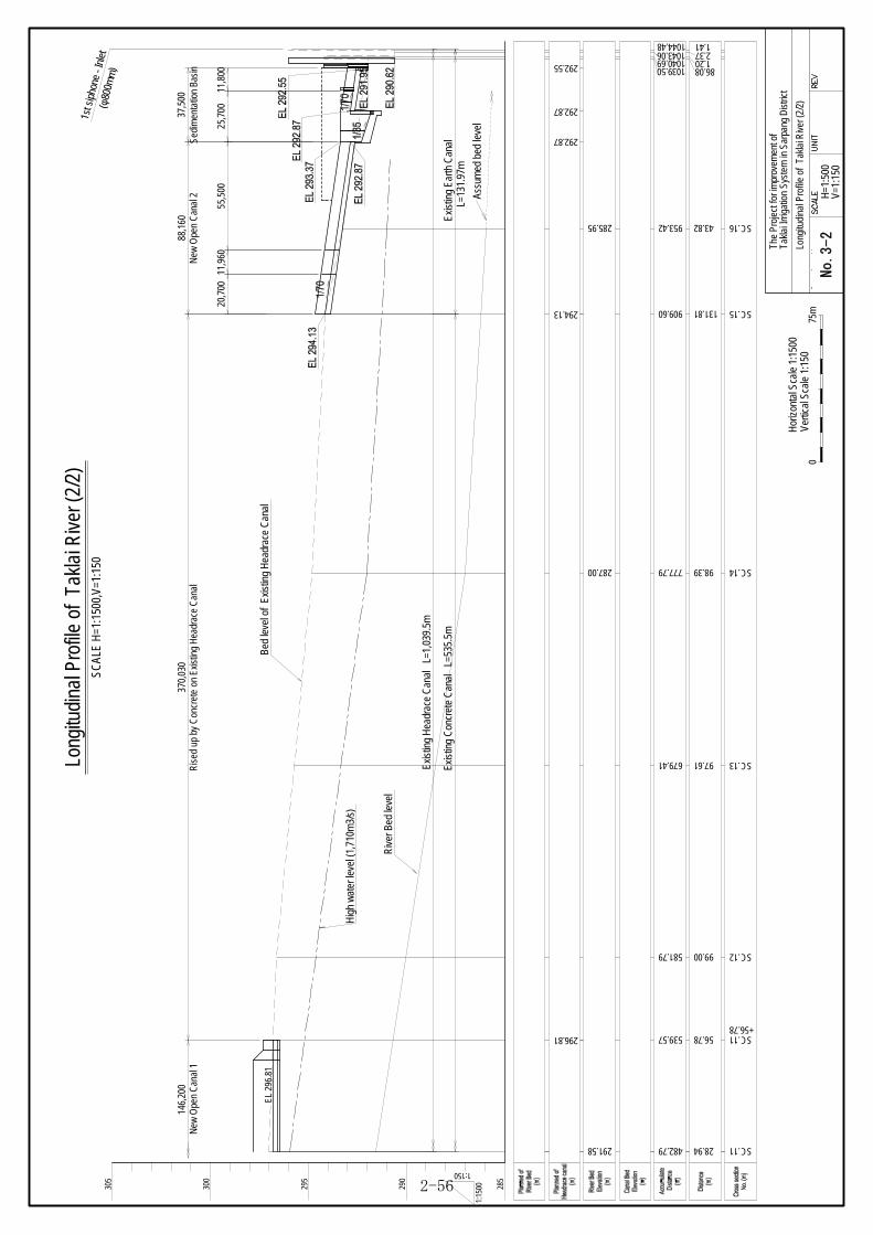
295
300
305
290
SC.12
SC.13
SC.14
SC.15
SC.16
581.79
679.41
777.79
909.60
953.42
SC.11482.79
Hor
izon
tal S
cale
1:1
500
Verti
cal S
cale
1:1
500
75m
03-2Ta
klai
Irrig
atio
n Sy
stem
in S
arpa
ng D
istric
t
H=1
:500
V=1:
150
The
Proj
ect f
or im
prov
emen
t of
Long
itudi
nal P
rofil
e of
Tak
lai R
iver (
2/2)
1:15
00
1:150
285
291.58
285.95
1st s
ipho
ne -
Inle
t(φ
800m
m)
Exis
ting
Hea
drac
e C
anal
L=
1,03
9.5m
Exis
ting
Con
cret
e C
anal
L=
535.
5mL=
131.
97m
Exis
ting
Earth
Can
al
Bed
leve
l of
Exis
ting
Hea
drac
e C
anal
Riv
er B
ed le
vel
28.94
99.00
97.61
98.39
131.81
43.82
1.202.371.41
1039.501040.69
1044.481043.06
86.08
SCAL
E H
=1:1
500,
V=1:
150
Long
itudi
nal P
rofil
e of
Tak
lai R
iver
(2/2
)
Assu
med
bed
leve
l
20,7
0011
,960
55,5
0025
,700
11,8
00
294.13
292.87
292.87
292.55
88,1
60N
ew O
pen
Can
al 2
287.00
146,
200
New
Ope
n C
anal
1SC.11539.57 56.78
+56.78296.81
EL 2
96.8
1
370,
030
Ris
ed u
p by
Con
cret
e on
Exis
ting
Hea
drac
e C
anal
37,5
00Se
dim
enta
tion
Basin
Hig
h w
ater
leve
l (1,
710m
3/s)
No.3-2
2-56

00-0Ta
klai
Irrig
atio
n Sy
stem
in S
arpa
ng D
istri
ct
H=1
:250
Gen
eral
Pla
n of
Hea
d W
orks
Gen
eral
Pla
n of
Hea
d W
orks BH
1
BH 2
BH 3
BH
4
TBM
1
TBM
2
EL 3
01.5
EL 301.3
EL
301.
5
EL 300.55
EL 300.45
EL 300.32
EL 300.26
EL 3
03.5
EL 301.5
EL 3
00.5
Exis
ting
rock
Exi
stin
g ro
ck
(Wing)
1,500
3,350
600350
25,0001,000
3,90
05,
300
9,20
0
6,50
0
14,9
00
350
250
4,00
013
,000
12,900
38,900 9,450
10,5
00
200
27,6
00
3,50
0
8,200 1,250
2,500 1,900
(Bar screen)
23,5
00
2,30
01,
000
3,34
016
0
1,800900
650
EL
301.
5
Flow
1:2.
0
1/20
1,00
020
090
01,
200
EL
299.
0(be
d le
vel E
L 29
8.0)
8t B
lock
by
Bol
der C
oncr
ete
3,00
0
1,90
0 1001,00
01/15
0
20,0
00
1/15
0
1,30
0
9°38'15"
100
45,000
Riv
er G
augi
n S
tatio
nw
ith L
aser
Typ
e
C
D
C
D
EE
FF
GG
BBA
A
45°0'0"
1:1
Protection Work on Apron
Protection Work on Apron
3,30
0
200
5,500
43,150
1:5.
58
Box
cul
vert
Box
culv
ert
B x
H =
1.5
m x
1.0
m
400
5,310
Bar
scr
een
De
tail
40
S=
1:5
0
100
1,30
0
10040
8,70
0
460
4,00
0
Stee
l Bar
φ10
0
2,690
5,200
200
900
200
90039,800
3 5 30
2,45061
013
,000
4 ,0 9 0
3,100
1,70
0
2,400
1,700
950
5,910
12,6
50
4,400
8,590
5 ,5 90
3,15
0
3,95
07,
360
Gab
ion
300
120
300
128250122500
S=1/
10Se
c. A
-A
Fix
bolt
De
tail
of
Pro
tect
ion
Wo
rk o
n A
pro
n
Top
View S=
1/30
3000
@30
00
S=1/
30Si
de V
iew
600
@30
00
A A
50040kg/m Rail @300
H 2
50xB
125x
9.7x
6.9
H 2
50xB
125x
9.7x
6.9
Fix
bolt
40kg
/m R
ail
S=1/
10
Exp.
j t=
20m
mW
ater
sto
p B
=300
mm
Spac
er
Anch
or D
22
Det
ail
Spac
er
H 2
50xB
125x
9.7x
6.9
Flow
Anch
or D
22Fl
ow
40kg
/m R
ail
H 2
50xB
125x
9.7x
6.9
Hig
h st
reng
then
con
cret
e
@30
0
Bolder Concrete
Bolder Concrete
No.4
2-57

00-0Ta
klai
Irrig
atio
n Sy
stem
in S
arpa
ng D
istri
ct
H=1
:100
The
Proj
ect f
or im
prov
emen
t of
Long
itudi
nal S
ectio
n of
hea
d W
orks
Long
itudi
nal S
ectio
n of
hea
d W
orks
Sec
tion
A-A
S=
1:10
0
10,5
001,
000
200
900
1,24
0
3,34
010
,660
1,000
1,00
012
,000
1,00
04,
550
14,5
006,
000
27,0
00(B
ed P
rote
ctio
n)
1:0.2
EL
299.
0
EL
301.
5
160
Bar
scr
een
1,000
EL 3
00.0
1,000
1,0001,500
Bol
der C
oncr
ete
Hig
h st
reng
then
con
cret
e
3,500 500
4,000
500
Tie
bar D
19
pipe
φ30
pipe
φ30
250
Bold
er C
oncr
ete
Hig
h st
reng
then
con
cret
e
3,00
0
1,00
02,
000
Bold
er
Con
cret
e
Oil
pain
t50
0
EL
300.
5
2,100
850
EL 3
01.3
6,50
0
8t B
lock
by
Bol
der C
oncr
ete
250
950
500
2,500
1,100
600500
1,500
3,000
EL
300.
55E
L 30
0.45
Box
culv
ert
B x
H =
1.5
m x
1.0
m
3,90
35,
300
14,9
00B
ox C
ulve
rtB
ox C
ulve
rt
1:5.
58
Flow
1:0.2
500
1,30
01,
040
1,00
0
1,500
1,900
1,400
DL=
295.
0
10,5
001,
000
200
900
1,24
0
3,34
0
1,000
1,00
012
,000
1,00
04,
550
14,5
006,
000
2,000
1:0.2
EL 3
01.5
EL
299.
0
EL 3
03.5
EL 3
01.5
160
Bar s
cree
n
1,000
EL
300.
0
1,0001,500
Bol
der C
oncr
ete
Hig
h st
reng
then
con
cret
e
3,500 500
4,000
500
Tie
bar D
19
pipe
φ30
pipe
φ30
250
Bol
der C
oncr
ete
Hig
h st
reng
then
con
cret
e
3,00
0
1,00
02,
000
Bol
der
Con
cret
e
Oil
pain
t50
0
EL
300.
5
2,100
850
EL 3
01.3
10,6
606,
500
8t B
lock
by
Bol
der C
oncr
ete
250
950
500
2,500
1,100
600500
1,5002,500
1,30
0
1 :2 .
0
1,04
0
1:0.2
1,5001,500
3,000
1,000500
1,400
1,900
Flow
100
Sec
tion
B-B
S=
1:1
00
DL=
295.
0
27,0
00(B
ed P
rote
ctio
n)
1,100
300550250
Tie
bar D
19D
19 L
=1,0
00 @
1,00
0
1,00
0
Hig
h st
reng
then
con
cret
e
Bol
der C
oncr
ete
Tie
ba
r D
etai
lS
=1
:50
@10
00
EL 3
00.0
1,900
2,700
2,500
820
1/20
@10
00
@10
00
1/20
@10
00
3,50
0
2,000
500
200
800
400
1,800
1,000
510
Wat
er s
top
B=3
00
R=3
00R
=300
R=3
00
100
100
100
100
Wat
er s
top
B=30
0mm
R=3
00
1:1.0
1 :1 .0
1:0.5
1:0.5
pipe
φ30
@10
00
pipe
φ30
@10
00
No.5-1
2-58
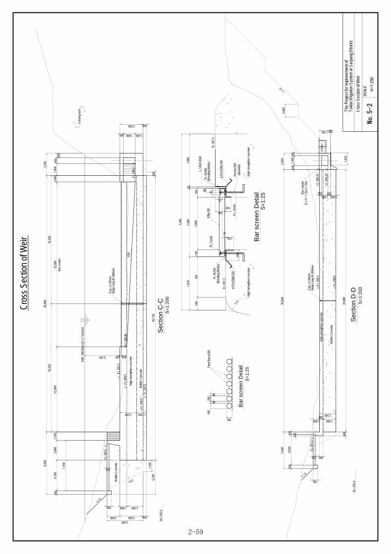
00-0Ta
klai
Irrig
atio
n Sy
stem
in S
arpa
ng D
istri
ct
H=1
:200
The
Proj
ect f
or im
prov
emen
t of
Cro
ss S
ectio
n of
Wei
r
HW
L 30
6.85
m (Q
=1,7
10m
3/s)
25,0
0012
,900
1,00
0
38,9
00
2,000
1,000 2,500
5003,500
Bar
scr
een
5,500
EL 3
00.5
EL
301.
5
3,35
0
3,500
1,2001,800500
5,350
1,25
0
9,45
0
600
350
1,50
0
39,8
00
EL
300.
5G
abio
n
EL
300.
55
1,000 1,000
1,85
0
100
350350
350
5,50
0
250
4,65
050
0
700
350 500
2,45
0
1,700
39,8
0060
0
Sec
tion
C-C
S=
1:20
0
Se
ctio
n D
-DS
=1
:200
EL
299.
20
EL
303.
5
4,70
03,
000
EL
301.
5
Box
cul
vert
B x
H =
1.5
m x
1.0
m
Exis
ting
rock
2,00
01:1.0
1 :1.0
43,1
501,
700
500
700
350
1:1 .0
DL=
295.
0
EL
298.
0
2,500
Bol
der C
oncr
ete
Hig
h st
reng
then
con
cret
e
500
Bol
der C
oncr
ete
Hig
h st
reng
then
con
cret
e
1,5002,500
1,80
090
065
0
EL
299.
22,000
500
850
1:0.5
1/20
EL
300.
45
200
Bol
der C
oncr
ete
7,70
0
Cro
ss S
ectio
n of
Wei
r
DL=
295.
0
1,000
EL 2
97.5
EL 2
98.0
5,20
050
0
19,4
5019
,450
Exp.
j t=
20m
mW
ater
sto
p B
=300
mm
Exp.
j t=
20m
mW
ater
sto
p B
=300
mm
PL-
9x50
0
Anc
hor B
olt
M24
x600
RBφ
100
L-12
0x12
0x8
PL-
12x5
0
PL-9
x350
PL-1
2x50
EL 3
01.5
EL
301.
3x
φ13
250@
250
xφ1
325
0@25
0
Hig
h st
reng
then
con
cret
e
(Ben
ding
Wor
ks)
(Ben
ding
Wor
ks)
150
12
25
100
200
200
200
30
70
80
246
764
1,01
01,
000
R 6 00
3,34
0
1,00
0
Bar
scr
een
Det
ail
S=
1:2
5
130
Hig
h st
reng
then
con
cret
e
100
100
40
100 40
Ba
r sc
ree
n D
eta
ilS
=1:
25
Ste
el B
ar φ
100
1,30
0
No.5-2
2-59
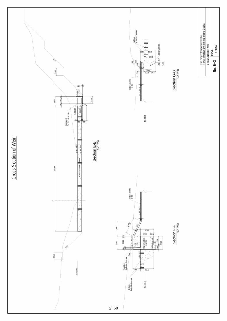
00-0Ta
klai
Irrig
atio
n Sy
stem
in S
arpa
ng D
istri
ct
H=1
:200
The
Proj
ect f
or im
prov
emen
t of
Cro
ss S
ectio
n of
Wei
r
C L
DL=
300.
0
EL 2
99.0
EL
300.
0
Se
ctio
n E
-ES
=1
:200
EL
300.
42
1,000 1,000350350
EL
299.
07
600
1,50
0
32,7
80
1,85
0
100
2,45
0
1,700
Gab
ion
350
Se
ctio
n F
-FS
=1
:200
4,00
0
350 25
02,
700
3,50
0
2,000
EL
301.
5
EL 3
03.5
EL
301.
5
2,000
DL=
300.
0
Se
ctio
n G
-GS
=1
:200
1,25
0
3,000
EL
301.
5
1,000
350
25060
0
750
500
DL=
300.
0
3,500
200
Box
cul
vert
B x
H =
1.5
m x
1.0
m
8t B
lock
by
Bol
der C
oncr
ete
1,00
0 250
2,25
0
3,50
0500
350
Bol
der C
oncr
ete
t=35
0 350
Bol
der C
oncr
ete
t=35
0
EL
300.
5
1,5001,500
2,00
01:1.0
2,00
0
1 :1 .0
Cro
ss S
ectio
n of
Wei
r
3,500
Flow
Flow
1:2.
0
Bac
kfille
dby
Bol
der C
oncr
ete
Bold
er C
oncr
ete
2,500
500
Hig
h st
reng
then
conc
rete
1,000
1,000
Bol
der C
oncr
ete
2,500
2,020
1,030
4,470
8t B
lock
by B
olde
r Con
cret
e
8t B
lock
by B
olde
r Con
cret
e
1,000
No.5-3
2-60

00-0Ta
klai
Irrig
atio
n Sy
stem
in S
arpa
ng D
istri
ct
H=1
:200
The
Proj
ect f
or im
prov
emen
t of
Cro
ss S
ectio
n of
Out
let o
f Box
Cul
vert(
1/2)
3to
n Block~
Gabi
onS=1:200
Cro
ss S
ectio
n of
Out
let o
f Box
Cul
vert(
1/2)
177°
0'0"
8ton Bl
ock~
3ton Block
3ton
Block
S=1:200
S=1:200
1,500350 350
2,200
1,500350 350
2,200
Box
culv
ert
B x
H =
1.5
m x
1.0
m
Box
culv
ert
B x
H =
1.5
m x
1.0
m
Gab
ion
Gab
ion
3ton
Blo
ck
Gab
ion
EL 299.49
2°0'0"
1/15
0
1,500350 350
2,200
1,500350 600
2,450
130,
000
1,00
050
,000
3ton
Blo
ck8t
on B
lock
Box
cul
vert
B x
H =
1.5
m x
1.0
mG
abio
n
3ton
Blo
ck8t
on B
lock
3ton
Blo
ck
3ton
Blo
ck
Gab
ion
Flow
Flow
Flow
2,000
2,0002,000
No.6-1
2-61

00-0Ta
klai
Irrig
atio
n Sy
stem
in S
arpa
ng D
istri
ct
H=1
:100
The
Proj
ect f
or im
prov
emen
t of
Cro
ss S
ectio
n of
Out
let o
f Box
Cul
vert(
2/2)
Sec
tion J-J
S=1:100
EL
300.
02
Gab
ion
1,700
2,700
1,000
1,85
0
100
8t C
oncr
ete
bloc
k
DL=
297.
0
1,700
EL
299.
49
Gab
ion
1,60
0
DL=
297.
0
Box
cul
vert
B x
H =
1.5
m x
1.0
m
350
350
1,50
0 EL
298.
62
Gab
ion
Gab
ion
DL=
296.
0
C L
2,20
0
2,00
0
1:1.0
3t C
oncr
ete
bloc
k
1:0.5
1:0.5
1:0.5
Section
I-I
S=1:100
Secti
on H-H
S=1:100
Cro
ss S
ectio
n of
Out
let o
f Box
Cul
vert(
2/2)
Box
cul
vert
B x
H =
1.5
m x
1.0
m
Box
culv
ert
B x
H =
1.5
m x
1.0
m
600
350
1,50
0
2,45
0
350
350
1,50
0
2,20
0
3501,000350
1001,700
3501,000
1001,700
3501,000
1,700
2,700
1,000
1,700
2,700
1,000
350
350
200 70
0
200 70
0
1,60
0
200 70
0
2,00
02,
000
2,00
0
2,00
0
1,000
1,000
1,000
No.6-2
2-62
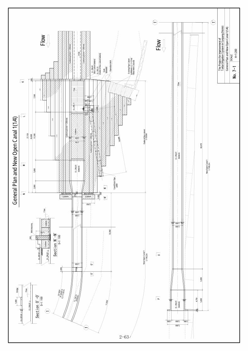
16,0
00
Wet masonry
GabionsWet masonry
Gabions
R=2
8.85
m
23°3
0'0"
CL=
11.8
3 m
EL 2
96.8
1(b
otto
m)
Brid
ge
68,4
70
3,000
1
1
5,00
05,
000
1'
1'
Gen
eral
Pla
n an
d N
ew O
pen
Can
al 1
(1/4
)
00-0Ta
klai
Irrig
atio
n Sy
stem
in S
arpa
ng D
istri
ct
H=1
:200
The
Proj
ect f
or im
prov
emen
t of
Gen
eral
Pla
n an
d N
ew O
pen
Can
al 1
(1/4
)
Exi
stin
g P
ipe
Cul
vert
(φ90
0mm
x 2
, L=2
.5m
)
55,9
00
1,00
0 500
2,950
Gab
ions
500
680
Gab
ions
Flow
EL
297.
81
Wet
mas
onry
1,00
0
2,500
2502,000250
2,500
3503,000350
3,700
2,80
0
750 25
0
5,00
011
,500
7,50
0
350
26,8
00
~G
abio
ns(φ
5mm
200m
m)
~G
abio
ns(φ
5mm
200m
m)
~G
abio
ns(φ
5mm
200m
m)
1,000 1,000
5,000
250
2502,000250
2,500
Gab
ions
250 250
KL
MN
OP
Flow
Flow
Out
let o
f Box
cul
vert
L=26
.8m
New
Ope
n C
anal
1
New
Ope
n C
anal
1L=
146.
2m
L=14
6.2m
1,500
1,50
0
600
2,100
760
1,140
EL
296.
81
(bot
tom
)
EL 2
96.8
1(B
ox c
ulve
rt bo
ttom
)
EL 2
95.3
1(O
utle
t of B
ox c
ulve
rt bo
ttom
)
EL
295.
11
EL 2
96.8
1
(bot
tom
)
EL
296.
81
(bot
tom
)
~G
abio
ns(φ
5mm
200m
m)
27,1
50
27,1
50
19,3
50
13,6
00
7,85
0
23,0
40
20,4
80
17,9
30
12,6
90
9,96
0
7,23
0
4,46
0
1,69
0
1,670
11,8
30 4,75
0
1/15
0
Fille
d W
ith C
oncr
ete
Gat
e80
0x80
0
Ope
ratio
n de
ck
5,00
0
27,1
50
Section N
'-N'
S=1:100
N'
N'
1,00
0
Flow
EL
297.
81
Brid
ge
Section
O'-O'
S=1:100
O'
O'
EL
296.
81
EL
296.
81
150
2500
San
d D
rain
Pip
eφ8
00
Flow
Flow
No.7-1
2-63

00-0Ta
klai
Irrig
atio
n Sy
stem
in S
arpa
ng D
istri
ct
H=1
:100
The
Proj
ect f
or im
prov
emen
t of
Gen
eral
Pla
n an
d N
ew O
pen
Can
al 1
(2/4
)
Gen
eral
Pla
n an
d N
ew O
pen
Can
al 1
(2/4
)
EL
298.
31
EL
295.
31
EL 2
96.8
1
~G
abio
ns(φ
5mm
200m
m)
~G
abio
ns(φ
5mm
200m
m)
EL 2
96.8
1
11,1
50
2,80
05,
000
1,000 350
3,200
1,000 250
EL
295.
11
Lon
gitudi
nal section of O
utlet of Box Cul
vert o
n right side
S=1:100
DL=
295.
0
136,
200
7,85
035
026
,800
750
250
1,500
3,000
EL
297.
81
EL 2
96.8
1
350
700
1,7001,500
1,5001,000500
K
350
Tie
bar
1,000
500
250
DL=
295.
0
250
5,00
05,
000
136,
200
EL
296.
81
250
750 100
EL
297.
31
EL 2
97.8
1
EL
296.
81
EL 2
98.3
1
EL
295.
31
EL 2
96.8
1
~G
abio
ns(φ
5mm
200m
m)
~G
abio
ns(φ
5mm
200m
m)
EL
296.
81
11,1
50
2,80
05,
000
1,000 350
3,000
3,200
EL 2
97.8
1
EL 2
95.1
1
250
500
750
DL=
295.
0
1,000
1,000 250
26,8
0035
0
7,85
0
EL
297.
81
700
1,7001,500
1,5001,000500
350
Gat
e80
0x80
0
LM
N
OP
Longitudinal section of Outlet of Box Culvert on left side
S=1:100
55,9
0011
,830
150
1,00
068
,470
1,000
500
250
DL=
295.
0
250
5,00
05,
000
136,
200
EL
296.
81
250
750 100
EL 2
97.3
1
EL
297.
81
EL
296.
81
55,9
0011
,830
150
1,00
068
,470
136,
200
Brid
ge2
Brid
ge2
250
250
350
250
150
3503
50
800350350
1,500
700
350
350
350
800350350
1,500
700
Flow
Flow
Flow
Flow
8,45
0
6,00
01,
500
350
10,9
0025
0
10,9
00
7,80
0
7,80
0
Out
let o
f Box
cul
vert
L=26
.8m
New
Ope
n C
anal
1L=
146.
2m
New
Ope
n C
anal
1L=
146.
2m
Out
let o
f Box
cul
vert
L=26
.8m
New
Ope
n C
anal
1L=
146.
2m
New
Ope
n C
anal
1L=
146.
2m
2,000
2,500
350
350
250
250
250
500
8,65
0
11,0
004,
750
2,80
0
2,350
1,250
2,850
1,750
1,350
Brid
ge1
Brid
ge1
D16
L=1
000
@50
0mm
Tie
bar
D16
L=1
000
@50
0mm
Tie
bar
D16
L=1
000
@50
0mm
Tie
bar
D16
L=1
000
@50
0mm
Tie
bar
D19
L=5
00 @
200m
m
1/15
0
No.7-2
2-64

00-0Ta
klai
Irrig
atio
n Sy
stem
in S
arpa
ng D
istri
ct
H=1
:100
The
Proj
ect f
or im
prov
emen
t of
Gen
eral
Pla
n an
d N
ew O
pen
Can
al 1
(3/4
)
350
350
1,50
0
EL 2
98.3
1
EL
296.
81
EL 2
95.3
1EL
295
.11
1,500
2,10
0
EL
297.
26
EL
296.
26
DL=
293.
0
350
3,00
035
0
3,70
060
0
150100
3503,200
3,550
3,300250
3,550
1,000
EL 2
96.8
13,00
035
035
0
2,850
1,500
1,000
C L
3,70
09,
000
350
350
2,350
100
EL 2
97.8
1
DL=
295.
0
2,00
0
1:1.0
2,00
0
1:1.0
2,00
0
1:1.0
~G
abio
ns(φ
5mm
200m
m)
~G
abio
ns(φ
5mm
200m
m)
Gab
ion
1,000
1,000
Gab
ions
~G
abio
ns(φ
5mm
200m
m)
Section K
-KS=1:100
Section L
-LS=1:100
Gen
eral
Pla
n an
d N
ew O
pen
Can
al 1
(3/4
)
2,20
0
3,90
0
3,90
0
800
4,00
0
2,00
0
1,000
1,0001,000
1,000
4,00
0
~G
abio
ns(φ
5mm
200m
m)
5,00
0
2,00
0
5,50
0
6,50
0
Gab
ions
~(φ
5mm
200m
m)
Gab
ions
~(φ
5mm
200m
m)
Ope
ratio
n de
ck
Sta
irs
250
250
1,00
0
750
Stai
rs
1,000
1,000
No.7-3
2-65

00-0Ta
klai
Irrig
atio
n Sy
stem
in S
arpa
ng D
istri
ct
H=1
:100
The
Proj
ect f
or im
prov
emen
t of
Cro
ss S
ectio
n of
Out
let o
f Box
Cul
vert(
2/2)
Sec
tion J-J
S=1:100
EL
300.
02
Gab
ion
1,700
2,700
1,000
1,85
0
100
8t C
oncr
ete
bloc
k
DL=
297.
0
1,700
EL
299.
49
Gab
ion
1,60
0
DL=
297.
0
Box
cul
vert
B x
H =
1.5
m x
1.0
m
350
350
1,50
0 EL
298.
62
Gab
ion
Gab
ion
DL=
296.
0
C L
2,20
0
2,00
0
1:1.0
3t C
oncr
ete
bloc
k
1:0.5
1:0.5
1:0.5
Section
I-I
S=1:100
Secti
on H-H
S=1:100
Cro
ss S
ectio
n of
Out
let o
f Box
Cul
vert(
2/2)
Box
cul
vert
B x
H =
1.5
m x
1.0
m
Box
culv
ert
B x
H =
1.5
m x
1.0
m
600
350
1,50
0
2,45
0
350
350
1,50
0
2,20
0
3501,000350
1001,700
3501,000
1001,700
3501,000
1,700
2,700
1,000
1,700
2,700
1,000
350
350
200 70
0
200 70
0
1,60
0
200 70
0
2,00
02,
000
2,00
0
2,00
0
1,000
1,000
1,000
No.7-4
2-66

00-0Ta
klai
Irrig
atio
n Sy
stem
in S
arpa
ng D
istri
ct
H=1
:200
The
Proj
ect f
or im
prov
emen
t of
New
Ope
n C
anal
2 a
nd S
edim
enta
tion
Basin
(1/3
)
New
Ope
n C
anal
2 a
nd S
edim
enta
tion
Basi
n(1/
3)
Lc
Rc
BM
2
250
roug
h ro
ad
1 1
1'
1'
Flow
Flow
3,500
250
750
750
1,000
1,000
2503,500250
4,000
2003,500200
3,900
10,3
5055
,500
10,3
5011
,800
3503,5001503,500350
7,850
2503,500250
4,000
1,00
0
3553,500355
2543,5001503,500254
350 350
250
250W
et s
tone
pitc
hing
67,6
00
Mai
nten
ance
gat
eH
x B
= 0
.5 x
1.5
5
Brid
ge
San
d D
rain
Pip
eB
x H
= 1
.0m
x 1
.0m
Wet
sto
ne p
itchi
ng
Wet
sto
ne p
itchi
ng
1:1
Wet
sto
ne p
itchi
ng
1:1
Wet
sto
ne p
itchi
ngW
et s
tone
pit c
hing
Wet
sto
ne p
itchi
ng
1:1
1:1
1:1
1:1
55,5
00
20,7
00
R=56
.85
m
CL=1
1.96
m
12°2
'55"
11,9
60
Dem
oliti
on o
f the
exi
stin
g w
all
5,00
0
5,00
05,
350
5,35
05,
000
7,658
4,210
5,890
6,090
1,50
03,
500
15,0
00
400
1,90
0
250
Sed
imen
tatio
n Ba
sin
L=37
.5m
New
Ope
n C
anal
2L=
88.1
6m
New
Ope
n C
anal
2L=
88.1
6m
500
960
30,1
00
1,5501,550
Gat
eB
x H
= 1
.0m
x 1
.0m
37,5
00
150
150
4,110
1/70
1/35
1/70
1/70
1/35.6
S=1:200
Gen
eral
Pla
n of
New
Ope
n C
anal
2
S=1:200
Gen
eral
Pla
n of
Sed
imen
tatio
n Ba
sin
No.8-1
2-67

00-0Ta
klai
Irrig
atio
n Sy
stem
in S
arpa
ng D
istri
ct
H=1
:100
The
Proj
ect f
or im
prov
emen
t of
New
Ope
n C
anal
2 a
nd S
edim
enta
tion
Basin
(2/3
)
New
Ope
n C
anal
2 a
nd S
edim
enta
tion
Basi
n(2/
3)
EL
292.
87EL
292
.55
EL
291.
95
Bol
der c
oncr
ete
EL 2
90.6
2
Exis
ting
gate
H x
B =
1.1
x 1
.15
Con
cret
e
Wet
sto
ne p
itchi
ng
1:1
1:1
Wet
sto
ne p
itchi
ng
25,7
00
10,3
50
1,00
0
11,8
00
200
1,50
020
0
15,3
50
1,00
0
1,000
250
67,6
00W
et s
tone
pitc
hing
1,90
0
645350
350
15,0
005,
150
10,1
00
U
500
W
Section R-R
-2S=1:100
EL
292.
87E
L 29
2.87
EL
293.
37
Ope
ning
1/35
1:1
Wet
sto
ne p
itchi
ng
B x
H =
1.0
m x
1.0
m
88,1
6025
700
15,3
50
350
67,6
00W
et s
tone
pitc
hing
600
710
595350
350
ST
5,35
015
000
1:1
Wet
sto
ne p
itchi
ng
1/70
DL=
290.
0
500
250
EL
294.
13
1 11'
1'
Secti
on R-R-1
S=1:100
Flow
Flow
Mai
nten
ance
gat
eH
x B
= 0
.5 x
1.5
5
150
350
350
350
350
V
Q
EL
294.
30
EL
294.
30
EL
294.
30
DL=
290.
0
Brid
ge
87,8
1035
0 350
87,4
60
5,00
05,
000
10,3
5022
01,
850
2,93
035
0
550
20,8
00
4,65
05,
350
10,8
001,
000
10,0
00
1,100
500
1,400
350
1,500
3,50
01,
500
5,00
0
1,250
1,450
1,550
9,65
0
1,750
1,830
2,050
750
750
255
255
1,600
200
1,000
500
960
960
1,250
22,1
50
2,250
500100
Tie
bar
D16
L=1
000
@50
0mm
Tie
bar
D16
L=1
000
@50
0mm
Tie
bar
D16
L=1
000
@50
0mm
T'
1:1.0
1:1.0
3,36
0
1:1.0
930
1/70
ST
QT'
UW
V
No.8-2
2-68

Section S
-SS=1:100
250
3,50
025
0
4,00
0
500 250
750
Sec
tion T
-TS=1:100
350
7,15
035
0
7,85
0
1,400 350
1,750
C L
3,50
015
03,
500
350
350
7,85
0
Section
U-U
S=1:100
250
5,70
025
0
6,20
0
500 250
750
2,77
515
02,
775
250
250
6,20
0
Sec
tion W
-WS=1:100
250
3,50
025
04,
000
500 250
750
C L C L
C L
00-0Ta
klai
Irrig
atio
n Sy
stem
in S
arpa
ng D
istri
ct
H=1
:100
The
Proj
ect f
or im
prov
emen
t of
New
Ope
n C
anal
2 a
nd S
edim
enta
tion
Basin
(3/3
)
New
Ope
n C
anal
2 a
nd S
edim
enta
tion
Basi
n(3/
3)
Section Q
-QS=1:100
250
3,50
025
0
4,00
0
500 250
750
C L
EL 2
94.1
3
1,00
03,
500
1,00
0
DL=
292.
0
Sec
tion V
-VS=1:100
250
3,50
025
0
4,00
0
500 250
750
C LBr
idge 1,
550
400
1,55
0
150
100
100100
100
100
100
750
750
550
100
200
450
20045
0
250
Sec
tion T'-T'
S=1:100
350
7,15
035
0
7,85
0
1,500 550
2,050
3,50
015
03,
500
350
350
7,85
0
C L
100
1/35
.6
Gat
eB
x H
= 1
.0m
x 1
.0m
San
d D
rain
Pip
eB
x H
= 1
.0m
x 1
.0m
1,000
200
No.8-3
2-69

(m)
Dis
tanc
e
(m)
Dis
tanc
e
260
Hor
izon
tal S
cale
1:1
000
Verti
cal S
cale
1:1
000
50m
03-1Tak
lai I
rrig
atio
n S
yste
m in
Sar
pang
Dis
tric
t
H=1
:100
0V=
1:50
0
Th
e P
roje
ct fo
r im
prov
emen
t of
Long
itud
inal
Pro
file
of
Can
dida
te S
ite fo
r P
rote
ctio
n D
ike
No.
(m)
Cro
ss s
ectio
n
Accu
mul
ate
SCAL
E H
=1:1
000,
V=1:
100
Long
itudi
nal P
rofil
e of
Can
dida
te S
ite fo
r Pro
tect
ion
Dik
e
1:10
00
1:100
(m)
Elev
atio
nR
iver
Bed
265
270
265.87 0.00265.59 2.16265.10 5.58
264.63 12.63
264.69 22.42
264.31 37.17
264.39 42.52
264.30 55.17
264.45 61.97
264.01 81.26
264.02 100.68
264.55 122.07
264.42 141.98
264.27 163.62
264.05 174.99
263.89 180.40
263.78 194.79
264.05 202.82
263.73 209.81
263.71 216.76
263.66 223.33
263.74 229.73
263.81 236.92
263.66 244.53
263.62 252.21
262.97 277.49
263.17 284.37
262.83 289.53
263.23 294.59
262.99 300.18
263.36 305.96
263.25 310.96
263.19 315.98
263.43 321.57263.31 326.02
263.13 331.75
262.85 338.47
0002.163.42
7.05
9.79
14.75
5.35
12.65
6.80
19.29
19.42
21.39
19.91
21.64
11.37
5.41
14.39
8.03
6.99
6.95
6.57
6.40
7.19
7.61
7.68
25.28
6.88
5.16
5.06
5.59
5.78
5.00
5.02
5.594.45
5.73
6.72
NO.1
NO.2
NO.3
NO.4
NO.5
NO.6
NO.7
450
3,0003,900
2,00
0
1,07
093
0
2,00
0
2,000
1,00
0
for t
he b
ed p
rote
ctio
nG
abio
ns
~(φ
5mm
20
0mm
)
Prot
ectio
n w
all
EL 2
93.0 ~
290.
0
aa
a-a
3,900
1,000 1,000
(Protection wall)
(Gabion) (Gabion)
EL 2
64.4
(U.S
)~
262.
2 (D
.S)
for t
he b
ed p
rote
ctio
nG
abio
ns
~(φ
5mm
20
0mm
)
Gen
eral
Pla
n fo
r the
Pro
tect
ion
Dik
e SC
ALE
=1:1
50
400
Fille
d w
ith b
olde
r and
san
d
L=34
0.00
m
1,0003,000
EL 2
67.4
(U.S
)~
265.
2 (D
.S)
1:1.51 :1 .5
Tem
pora
ry D
ike fo
rm
Tem
pora
ry D
ike
form
Not
e) A
t firs
t, th
e te
mpo
rary
dik
e fo
rm s
hall b
e em
bank
ed d
uly.
Seco
nd, t
he te
mpo
rary
dik
e fo
rm s
hall
be c
ut to
set
the
gabi
ons.
900
100
No.9
2-70
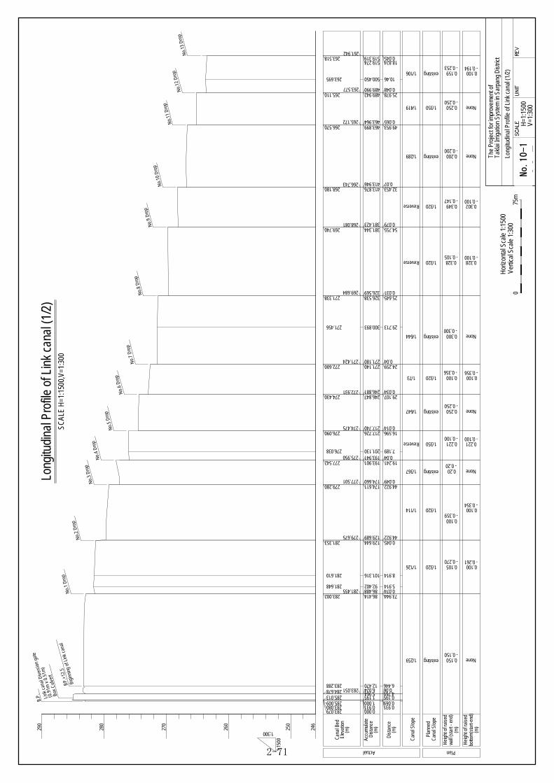
(m)
Dist
ance
(m)
Elev
atio
n
(m)
Dis
tanc
e
(m)
wal
l (st
art -
end
)
1:15
00
1:300260
270
280
250
Can
al B
ed
Accu
mul
ate
Can
al S
lope
Can
al S
lope
Plan
ned
Hei
ght o
f rai
sed
(m)
botto
m(s
tart-
end)
Hei
ght o
f rai
sed
Actual Plan
0.000283.0790.931283.0801.000285.0091.195285.0135.964284.678 6.024283.051
12.470283.288
86.414283.00286.488281.45592.402281.648
101.316281.610
129.644281.353129.689279.675
174.611279.280174.660277.501
193.901277.542193.941275.950201.130276.038
217.726276.090217.740274.475
246.847274.430246.881272.931
271.140272.600271.180271.424
300.893271.456
326.538271.338326.569269.684
381.344269.740381.423268.081
413.876268.180413.946266.743
463.899266.570463.964265.172
489.942265.110489.990263.577
500.450263.695
519.274263.518 519.319
261.942
290
246
Box
Cul
vert
(0.9
1m x
0.5
1m)
Link
can
al D
iver
sion
gat
e
0.0690.1954.7690.06
6.446
73.9440.0745.914
8.914
0.04544.922
44.9220.049
19.2410.04
7.189
16.5960.014
29.1070.034
24.2590.04
29.713
25.6450.031
54.7550.079
32.4530.07
49.9530.065
25.9780.048
10.46
18.8240.045
1/259 existing
1/126 1/320
1/114 1/320
1/367 existing
Reverse 1/350
1/647 existing
1/73 1/320
1/644 existing
Reverse 1/320
1/289 existing
1/419 1/350
1/106 existing
SCAL
E H
=1:1
500,
V=1:
300
Long
itudi
nal P
rofil
e of
Lin
k ca
nal (
1/2)
0.931
Reverse 1/320
Hor
izon
tal S
cale
1:1
500
Verti
cal S
cale
1:3
000
75m
00-1Ta
klai
Irrig
atio
n Sy
stem
in S
arpa
ng D
istri
ct
H=1
:150
0
The
Proj
ect f
or im
prov
emen
t of
Long
itudi
nal P
rofil
e of
Lin
k ca
nal (
1/2)
V=1:
300
B.P.
Bigi
nnin
g of
Lin
k ca
nal
BP.
+12.
5N
o.1
Dro
p
No.
2 D
rop
No.
3 D
rop
No.
4 D
rop
No.
5 D
rop
No.
6 D
rop
No.
7 D
rop
No.
8 D
rop
No.
9 D
rop
No.
10 D
rop
No.
11 D
rop
No.
12 D
rop
No.
13 D
rop
- 0.150None
- 0.2700.100
- 0.3590.100
- 0.20None
- 0.100
- 0.250
- 0.356
- 0.300
- 0.105
- 0.200
- 0.250
- 0.147
0.221
None
0.100
None
0.328
None
None
0.302
0.150
0.105
0.100
0.20
0.221
0.250
0.100
0.300
0.328
0.200
0.250
0.349
- 0.261
- 0.354
- 0.100
- 0.356
- 0.100
- 0.100
- 0.2530.100 0.159 - 0.194
No.10-1
2-71

(m)
Dist
ance
(m)
Elev
atio
n
(m)
Dis
tanc
e
(m)
wal
l (st
art -
end
)
1:15
00
1:300260
270
280
250
Can
al B
ed
Accu
mul
ate
Can
al S
lope
Can
al S
lope
Plan
ned
Hei
ght o
f rai
sed
(m)
botto
m(s
tart-
end)
Hei
ght o
f rai
sed
Actual Plan
489.942265.110489.990263.577
500.450263.695
519.274263.518 519.319
261.942 523.211262.091523.410263.636528.264
263.605
528.329262.080
548.242261.990548.296260.582554.120260.895
597.397260.607 597.463258.827
599.619258.868
650.864258.744650.873257.218
693.797257.178693.815255.724699.598255.642
739.336255.440739.380253.922
774.190253.790774.208252.141
800.149252.050
820.809251.907820.850250.412
874.700249.864 874.734
248.724 877.678248.561
900.335
248.697
973.519247.651
984.306246.934
290
246
Box
Cul
vert
25.9780.048
10.46
18.8240.0453.8920.1994.8540.065
19.9130.0485.83
43.2770.0662.156
51.2450.009
42.9240.0185.783
0.044
34.810.018
25.941
20.660.041
53.850.0342.944
17.034
31.277
10.787
1/106 existing
1/221 existing
1/150 existing
1/413 existing
1/1073 existing
1/1073 existing
1/264 existing
1/199 existing
1/98 1/320
1/50
No.
12 D
rop
No.
13 D
rop
No.
14 D
rop
No.
15 D
rop
No.
16 D
rop
No.
17 D
rop
No.
18 D
rop
No.
19 D
rop
No.
20 D
rop
No.
21 D
rop
+8.5
7+2
5.6
+67.
51+1
09.5
7
Hor
izon
tal S
cale
1:1
500
Verti
cal S
cale
1:3
000
75m
00-2Ta
klai
Irrig
atio
n Sy
stem
in S
arpa
ng D
istri
ct
H=1
:150
0
The
Proj
ect f
or im
prov
emen
t of
Long
itudi
nal P
rofil
e of
Lin
k ca
nal (
2/2)
V=1:
300
883.301
942.242
5.623
41.907
None
None
None
None
None
- 0.100
- 0.517
None
None
None
None
None
None
None
0.100
0.100
0.138- 0.479
recon-struction
(elevation)
SCAL
E H
=1:1
500,
V=1:
300
Long
itudi
nal P
rofil
e of
Lin
k ca
nal (
2/2)
+2.9
4
249.109Plan
ned
cana
l bed
1/320
1450
248.513
(drop)
248.724
1/320recon
-struction
248.513
247.063(elevation)
(elevation)
246.934(elevation)
+68.
24
942.967 0.725 (Drop)
- 0.2530.100 0.159 - 0.194
- 0.1000.100
No.10-2
2-72

DL=
276.
00
DL=
275.
00
00-1Tak
lai I
rrig
atio
n S
yste
m in
Sar
pang
Dis
tric
t
0
SCAL
E: 1
:100
5m
S=1:
100
SCAL
E =1
:100
Cro
ss S
ectio
n of
Lin
k C
anal
(1/4
)
Th
e P
roje
ct fo
r im
prov
emen
t of
Cro
ss S
ectio
n o
f Lin
k C
anal
(1/
4)
BP.+
12.5
- N
o.1
DL=
284.
500
No.
1 -
No.
2
DL=
281.
500
(Sta
rt Po
int)
DL=
281.
500
No.
2 -
No.
3
DL=
279.
500
DL=
279.
500
DL=
277.
500
DL=
276.
00
(End
Poi
nt)
DL=
283.
000
No.
5 -
No.
6
No.
3 -
No.
4
No.
4 -
No.
5
(Sta
rt Po
int)
(End
Poi
nt)
(Sta
rt Po
int)
(End
Poi
nt)
(Sta
rt Po
int)
(End
Poi
nt)
(Sta
rt Po
int)
(End
Poi
nt)
(Sta
rt Po
int)
(End
Poi
nt)
DL=
274.
00
DL=
277.
500
Stan
dard
cro
ss s
ectio
n fo
r im
prov
emen
t SC
ALE
=1:5
0
401
372
200
200
355
331
Gro
und
line
Rai
sed
up w
all
by w
et m
ason
ry
cut l
ine
C L
C m
2Exca
vatio
nB
m2
Rai
sed
up b
otto
mby
con
cret
eD
m2
(L=7
4m)
(L=4
3m)
(L=4
5m)
(L=1
9m)
(L=2
4m)
(L=2
9m)
A m
401
374
355
331
524
491
615
576
200
200
452
423
452
423
200
200
200
200
474
411
352
309
502
435
502
435
EL 2
84.6
78EL
283
.002
EL 2
81.7
48
EL 2
79.7
75
EL 2
81.6
14
EL 2
79.6
34
EL 2
77.5
80EL
277
.542
EL 2
76.2
59EL
276
.190
EL 2
74.4
75EL
274
.43
(Chipping)
1:0.5
existing
slope
U.S
U.S
D.S
U.S
D.S
U.S
D.S
U.S
D.S
U.S
D.S
No.11-1
2-73

No.
6 -
No.
7
DL=
273.
00D
L=27
3.00
No.
7 -
No.
8
DL=
271.
50
No.
8 -
No.
9
DL=
269.
50D
L=26
9.50
No.
9 -
No.
10
DL=
268.
00D
L=26
8.00
No.
10
- N
o.11
DL=
266.
50
No.
11
- N
o.12
DL=
265.
00
00-2Tak
lai I
rrig
atio
n S
yste
m in
Sar
pang
Dis
tric
t
0
SCAL
E: 1
:100
5m
S=1:
100
SCAL
E =1
:100
Cro
ss S
ectio
n of
Lin
k C
anal
(2/4
)
Th
e P
roje
ct fo
r im
prov
emen
t of
Cro
ss S
ectio
n o
f Lin
k C
anal
(2/
4)
(Sta
rt Po
int)
(End
Poi
nt)
(Sta
rt Po
int)
(End
Poi
nt)
(Sta
rt Po
int)
(End
Poi
nt)
(Sta
rt Po
int)
(End
Poi
nt)
(Sta
rt Po
int)
(End
Poi
nt)
(Sta
rt Po
int)
(End
Poi
nt)
DL=
271.
00D
L=26
6.50
(L=2
4m)
(L=5
5m)
(L=5
5m)
(L=3
3m)
(L=5
0m)
(L=2
6m)
DL=
265.
00
200
200
200
200
352
309
608
524
541
499
541
499
568
524
349
322
200
200
200
200
641
604
420
388
478
445
478
445
533
498
533
498
Stan
dard
cro
ss s
ectio
n fo
r im
prov
emen
t SC
ALE
=1:5
0
Gro
und
line
by w
et m
ason
ry
cut l
ine
C L
C m
2Exca
vatio
nB
m2
by c
oncr
ete
D m
2A
mR
aise
d up
wal
lR
aise
d up
bot
tom
EL 2
71.4
24EL
271
.338
EL 2
66.7
50EL
266
.743
EL 2
65.1
72EL
265
.110
EL 2
73.0
31
EL 2
69.8
40
EL 2
68.2
80EL
272
.956
EL 2
70.0
12
EL 2
63.3
83
(Chipping)
1:0.5
existing
slope
U.S
D.S
U.S
D.S
U.S
D.S
U.S
D.S
U.S
D.S
U.S
D.S
No.11-2
2-74

No.
12
- N
o.13
DL=
263.
5D
L=26
3.5
No.
13
- N
o.14
DL=
262.
0
No.
18
- N
o.19
DL=
254.
0
No.
19
- N
o.20
DL=
252.
0
No.
20
- N
o.21
DL=
250.
5D
L=24
9.5
00-3Tak
lai I
rrig
atio
n S
yste
m in
Sar
pang
Dis
tric
t
0
SCAL
E: 1
:100
5m
S=1:
100
SCAL
E =1
:100
Cro
ss S
ectio
n of
Lin
k C
anal
(3/4
)
Th
e P
roje
ct fo
r im
prov
emen
t of
Cro
ss S
ectio
n o
f Lin
k C
anal
(3/
4)
(Sta
rt Po
int)
(End
Poi
nt)
(Sta
rt Po
int)
(End
Poi
nt)
(Sta
rt Po
int)
(End
Poi
nt)
(Sta
rt Po
int)
(End
Poi
nt)
(Sta
rt Po
int)
(End
Poi
nt)
DL=
262.
0
DL=
254.
0
DL=
252.
0
(L=2
9m)
(L=2
9m)
(L=3
5m)
(L=4
7m)
(L=5
4m)
200
200
200
200
362
389
440
483
312
330
312
330
324
347
324
347
200
200
200
200
470
322
470
322
512
353
978
699
Stan
dard
cro
ss s
ectio
n fo
r im
prov
emen
t SC
ALE
=1:5
0
Gro
und
line
by w
et m
ason
ry
cut l
ine
(Chipping)
C L
C m
2Exca
vatio
nB
m2
1:0.5
existing
slope
by c
oncr
ete
D m
2A
m
No.
14
- N
o.18
(L=1
91m
)N
o ne
ed th
e im
prov
emen
t
Rai
sed
up w
all
Rai
sed
up b
otto
m
EL 2
62.0
80EL
261
.990
EL 2
53.9
22EL
253
.790
EL 2
52.1
41EL
251
.907
EL 2
63.7
95
EL 2
50.5
12
EL 2
63.7
12
EL 2
49.8
64
U.S
D.S
U.S
D.S
U.S
D.S
U.S
D.S
U.S
D.S
U.S
D.S
No.11-3
2-75

SCAL
E =1
:100
Cro
ss S
ectio
n of
Lin
k C
anal
(4/4
)
No.
21
00-4Tak
lai I
rrig
atio
n S
yste
m in
Sar
pang
Dis
tric
t
0
SCAL
E: 1
:100
5m
S=1:
100
Th
e P
roje
ct fo
r im
prov
emen
t of
Cro
ss S
ectio
n o
f Lin
k C
anal
(4/
4)
EL 2
49.1
05
EL 2
48.7
15EL
248
.513
DL=
248.
5
DL=
248.
5D
L=24
8.0
EL 2
48.6
97
EL 2
48.5
53
DL=
248.
0
DL=
248.
0
No.
21+2
.94
No.
21+8
.57
No.
21+2
5.6
No.
21+6
7.51 EL
247
.063
DL=
247.
0
No.
21+6
8.24
No.
21+1
09.5
7
EL 2
46.9
34
DL=
246.
5
Stan
dard
cro
ss s
ectio
n fo
r rec
onst
ruct
ion
SCAL
E =1
:50
C L
Exca
vatio
nB
m2
1:0.5
by c
oncr
ete
D m
2
Can
al b
otto
m
Wal
l by
wet
mas
onry
C m
2
Emba
nkm
ent
A m
2
Con
cret
cap
E m
2
1:0.5
(m2)
Gro
und
line
(m2)
(m2)
(m2)
(m2)
(m2)
0.14
(m2)
D.S
No.11-4
2-76

0.000294.212
2.057294.195 290.619
4.992290.6195.042295.994
HLC-2294.067
206.128294.125
230.646294.778 290.592
233.678290.592 292.075243.766292.052245.081292.407248.511292.113273.837292.009 290.842
277.320290.807 291.042
281.344289.528 289.806281.765289.803 289.732
307.149289.600 288.307310.562288.312 288.572311.080288.560 287.105314.631286.993 287.274315.183287.288 287.215
343.790287.060
346.592287.058
370.033286.918 287.038370.538287.049 285.685373.970285.636 285.918374.496285.911 285.804379.107285.793 285.846379.667285.833 285.775393.093285.509 285.664393.931285.662 283.892398.654283.831 284.053405.779284.142431.334283.927
505.788283.991
575.298283.966
587.528283.982
599.578284.024605.578283.979610.767283.979
622.550283.993
637.158283.938
705.496283.937
715.105283.964
734.105283.810738.283283.906741.521283.902
750.273283.914
763.827283.923
781.900283.877
803.962283.899
818.687283.890
828.714283.888
844.651283.830
871.890283.808
882.994283.837886.848283.850887.958283.850
904.594283.844
Accu
mul
ate
Dis
tanc
e
Elev
atio
n2(u
pper
)
Cro
ss S
ectio
nno
.
Siphon
Elev
atio
n1(d
own)
Dis
tanc
e
Gate
of S
iphon
1st S
iphon
(Inle
t)
Cros
s Brid
ge
B=2.
8m
Pipe
of A
qued
uct
Instr
umen
t Stat
ion
3.550290.619 HLC-1
HLC-3
HLC-4290.592
276.975290.811 HLC-5
232.182
305.867289.584 HLC-6
HLC-7
HLC-8
HLC-9
HLC-10
HLC-11
HLC-12
EL29
0.62
Botto
m L
evel
of S
ipho
nEL
290.
59Bo
ttom
Lev
el o
f Sip
hon
277.904291.012 289.544
1st S
iphon
(Outl
et)
1:25
00
1:250
280
285
290
295
300
305
Hor
izon
tal S
cale
1:2
500
Verti
cal S
cale
1:2
500
125m
Dra
wing
No. 03
-1SC
ALE
UN
ITRE
V.
Takl
ai Ir
rigat
ion
Syst
em in
Sar
pang
Dist
rict
H=1
:250
0V=
1:25
0
The
Proj
ect f
or im
prov
emen
t of
Long
itudi
nal P
rofil
e of
Hig
h Le
vel C
anal
(1/7
)
SCAL
E H
=1:2
500,
V=1:
250
Long
itudi
nal P
rofil
e of
Hig
h Le
vel C
anal
(1/7
)
HLC-0000
2.057
1.4420.050
100.280
24.518
1.49610.0881.3153.43025.326
0.345
3.4400.421
1.2823.4130.5183.5510.552
28.607
2.802
23.4410.5053.4320.5264.6110.56013.4260.8384.7237.12525.555
74.454
69.51
12.23
12.056.0005.198
11.783
14.608
68.338
9.609
19.0004.1783.238
8.752
13.554
18.073
22.062
14.725
10.027
15.937
27.239
11.1043.8541.110
16.636
1.493
3.138
1.536
24.102
0.584
Ref
eren
ceD
raw
ing
Rih
abilit
atio
nIte
m
1st S
ipho
n φ8
00m
m
Lege
nd
C.G
: C
heck
Gat
eD
.G :
Ditr
ibut
ion
Gat
e
Cros
s Brid
ge
B=3.
2m
Ris
en u
p w
all b
y 0.
1mL=
165.
0mR
ihab
ilitat
ion
of W
et M
ason
ry w
all
L=74
.5m
Cov
ered
by
conc
rete
L=2
05.8
m
Begin
ning
of H
igh L
evel
Cana
l
Gro
und
Leve
l
L=22
5.69
m
Inst
all t
he S
afet
y Sc
reen
x2
105.848 100.806
Inte
rval
AIn
terv
al B
300
2100
300
800
765
1650
765
3180
1700
Inte
rval
A :
Stan
dard
Sec
tion
SCAL
E 1:
100
Inte
rval
B :
Stan
dard
Sec
tion
SCAL
E 1:
100
1:0.45by
Mor
tare
dW
et M
ason
ryby
Mor
tare
dW
et M
ason
ry
No.12-1
2-77

904.594283.844
962.054283.808
973.829283.800
1006.046283.786
1008.807283.672
1012.741283.770
1049.467283.857
1062.667283.840
1070.557283.860
1076.889283.767
1107.051286.326
1161.315283.768
1170.676283.779
1183.142283.769
1198.896283.720
1215.883283.731
1231.063283.715
1270.987283.642
1302.371283.644
1305.742283.669
1317.108283.663
1335.048283.652
1346.347283.631
1380.264283.656
1409.425283.636
1432.345283.654
1450.190283.605
1461.991283.604
1478.944283.604
1508.230283.591
1529.448283.551
1529.739283.550
1530.360283.576
1540.342283.576
1543.417278.6681543.454285.261
1544.013285.261
1581.135285.136
1581.170278.8861583.866281.2671589.560283.4101598.364283.413
1599.137283.413
1607.880283.409
1626.889283.413
1645.730283.203
1658.746283.394
1661.650283.393
1699.252283.393
1710.270283.400
1725.156283.401
1743.950283.406
1762.041283.389
1775.979283.375
1796.743283.380
1809.192283.345
HLC-12
HLC-13
HLC-14
HLC-15
HLC-16
HLC-17
HLC-19
HLC-20
HLC-21
C.G.
1 2nd
Siph
on (in
let)
2nd
Siph
on (o
utlet
)
EL27
8.89
Botto
m L
evel
of S
ipho
nEL
278.
67Bo
ttom
Lev
el o
f Sip
hon
Accu
mul
ate
Dis
tanc
e
Elev
atio
n2(u
pper
)
Cro
ss S
ectio
nno
.
Elev
atio
n1(d
own)
Dis
tanc
e
1:25
00
1:250
270
275
280
285
290
295
300
Hor
izon
tal S
cale
1:2
500
Verti
cal S
cale
1:2
500
125m
Dra
win
g No
. 03-2
SCAL
EU
NIT
REV
.
Takl
ai Ir
rigat
ion
Syst
em in
Sar
pang
Dis
trict
H=1
:250
0V=
1:25
0
The
Proj
ect f
or im
prov
emen
t of
Long
itudi
nal P
rofil
e of
Hig
h Le
vel C
anal
(2/7
)
SCAL
E H
=1:2
500,
V=1:
250
Long
itudi
nal P
rofil
e of
Hig
h Le
vel C
anal
(2/7
)
16.636
57.460
11.775
32.217
2.761
3.934
36.726
13.200
7.890
6.332
30.162
54.264
9.361
12.466
15.754
10.439
15.18
39.924
31.384
3.371
11.366
17.940
11.299
39.917
29.161
22.920
17.845
11.801
16.953
29.236
21.218
0.291
0.621
9.982
3.0750.037
0.614
37.104
0.0352.6965.6948.804
0.773
8.743
19.009
18.841
13.016
2.904
37.602
11.018
14.866
18.794
18.091
13.938
20.764
12.499
Cros
s Brid
ge
B=3.
9m
L=85
mL=
7.9m
L=15
.8m
L=31
.4m
Lege
nd
C.G
: C
heck
Gat
eD
.G :
Ditr
ibut
ion
Gat
e
D.G.
1(Ex
pired
)
W x
H =
1.95
m x
1.4m
Cros
s Brid
ge
B=2.
9m
D.G.
2
W x
H =
0.5m
x 1.
5m
φ8
00 x
2pi
pe2n
d Si
phon
L=37
.7m
Rih
abilit
atio
n of
Wet
Mas
onry
wal
lL=
20.0
mR
ihab
ilitat
ion
of W
et M
ason
ry w
all
L=29
.2m
Rih
abilit
atio
n of
Sip
hon
inle
t
Rep
lace
the
D.G
.2
BxW
xH=2
.8m
x2.8
mx6
.6m
Ref
eren
ceD
raw
ing
Rih
abilit
atio
nIte
m
Cov
ered
by
conc
rete
on
Top
(t=0.
20)
Cov
ered
by
conc
rete
on
Top
(t=0.
20)
Inst
all t
he S
afet
y Sc
reen
x2
1205.444 6.548
HLC-18
Inte
rval
BIn
terv
al B
765
1650
765
3180
1700 Inte
rval
B :
Stan
dard
Sec
tion
SCAL
E 1:
100
1:0.45
by M
orta
red
Wet
Mas
onry
Reh
abilit
atio
n of
leak
ing
at A
qued
uct
L=10
m
Reh
abilit
atio
n of
leak
ing
at A
qued
uct
L=19
m
No.12-2
2-78

1809.192283.345
1822.535283.351
1825.507283.3561835.822283.351
1867.351283.261
1880.986283.315
1898.711283.278
1909.158283.290
1913.141283.292
1950.530283.225
1981.869283.179
1996.530283.178
2009.122282.934
2034.296283.179
2057.663283.139
2061.567283.129
2101.893283.1422109.342283.101
2123.795283.121
2133.968283.121
2147.052283.111
2163.676283.084
2190.576283.107
2226.714283.149
2244.546283.190
2258.560283.139
2258.717283.138
2259.440283.145
2287.669283.174
2318.658283.180
2326.527283.172
2345.807283.123
2377.141283.101
2398.102283.080
2441.344283.053
2471.736282.9862471.985282.9852472.648282.984
2503.281282.951
2567.721282.892
HLC-21
HLC-22
HLC-23
HLC-24
HLC-25
Accu
mul
ate
Dis
tanc
e
Elev
atio
n2(u
pper
)
Cro
ss S
ectio
nno
.
Elev
atio
n1(d
own)
Dis
tanc
e
1:25
00
1:250
280
285
290
295
300
Hor
izon
tal S
cale
1:2
500
Verti
cal S
cale
1:2
500
125m
Draw
ing
No. 03
-3SC
ALE
UNI
TR
EV.
Takl
ai Ir
rigat
ion
Syst
em in
Sar
pang
Dist
rict
H=1
:250
0V=
1:25
0
The
Proj
ect f
or im
prov
emen
t of
Long
itudi
nal P
rofil
e of
Hig
h Le
vel C
anal
(3/7
)
SCAL
E H
=1:2
500,
V=1:
250
Long
itudi
nal P
rofil
e of
Hig
h Le
vel C
anal
(3/7
)
270
275
12.499
13.343
2.97210.315
31.529
13.635
17.725
10.447
3.983
37.389
31.339
14.661
26.9
36.138
17.832
14.014
0.157
0.723
28.229
30.9897.869
19.280
31.334
20.961
43.242
30.3920.2490.663
30.633
64.44
Lege
nd
C.G
: Ch
eck
Gat
eD
.G :
Ditri
butio
n G
ate
Cros
s Brid
ge
B=3.
0mCo
ncre
te C
ross
Brid
ge
B x L
= 4
.0m
x 3.
2m
Conc
rete
Cro
ss B
ridge
B x L
= 4
.0m
x 3.
2mD.
G.3
W x
H =
0.9m
x 1.
6mC.
G.2
W x
H =
1.95
m x
1.5m
C.G.
3
D.G.
4W
x H
= 1.
95m
x 1.4
m
Rep
lace
the
Brid
geR
epla
ce th
e Br
idge
12.592
25.174
23.367
3.904
40.3267.449
14.453
10.173
13.084
16.624
2569.157282.892
2596.826282.856
2639.237282.792
2639.389282.792
2640.123282.789
2643.829282.762
2713.981282.738 HLC-26
1.436
27.669
42.411
0.152
0.754
3.686
70.152
Cros
s Brid
ge
B=1.
44m
C.G.
4
D.G.
5W
x H
= 1.
95m
x 1.4
m
W x
H =
0.5m
x 1.
45m
Ref
eren
ceD
raw
ing
Rih
abilit
atio
nIte
m
Begin
ning
of L
ink C
anal
W x
H =
0.5m
x 1.
6m
Inte
rval
B
765
1650
765
3180
1700 Inte
rval
B :
Stan
dard
Sec
tion
SCAL
E 1:
100
by M
orta
red
1:0.45
Wet
Mas
onry
Reh
abilit
atio
n of
leak
ing
at A
qued
uct
L=21
m
No.12-3
2-79

2713.981282.738
2735.699282.750
2779.052282.7342779.296282.734
2779.985282.705
2840.229282.652
2851.356282.616
2867.874282.642
2893.440282.606
2911.605282.586
2940.560282.5772940.865282.577
2941.554282.576
2966.849282.549
2978.241282.5552985.704282.535
2998.208282.565
3018.513282.600
3022.666282.595
3025.486282.555
3025.707282.523
3027.240284.197
HLC-26
EL28
1.92
Botto
m L
evel
of S
ipho
nEL
280.
44Bo
ttom
Lev
el o
f Sip
hon
3251.774283.950
3251.837280.440
3252.646280.440
3253.644280.440
3253.705281.511
3254.172282.2773259.522282.2243268.750282.235
3287.641282.2503294.195282.247
3316.114282.254
3334.212282.268
HLC-27
Accu
mul
ate
Dis
tanc
e
Elev
atio
n2(u
pper
)
Cro
ss S
ectio
nno
.
Elev
atio
n1(d
own)
Dis
tanc
e
1:25
00
1:250
280
285
290
295
300
Hor
izon
tal S
cale
1:2
500
Verti
cal S
cale
1:2
500
125m
Dra
win
g No
. 03-4
SCAL
EUN
ITR
EV.
Takl
ai Ir
rigat
ion
Syst
em in
Sar
pang
Dist
rict
H=1
:250
0V=
1:25
0
The
Proj
ect f
or im
prov
emen
t of
Long
itudi
nal P
rofil
e of
Hig
h Le
vel C
anal
(4/7
)
SCAL
E H
=1:2
500,
V=1:
250
Long
itudi
nal P
rofil
e of
Hig
h Le
vel C
anal
(4/7
)
270
275
70.152
21.718
43.3530.244
0.689
60.244
11.127
16.518
25.566
18.165
28.9550.305
0.689
25.295
11.3927.463
12.504
20.305
4.153
2.820
0.221
1.533
224.534
0.063
0.809
0.998
0.061
0.4675.3509.228
18.8916.554
21.919
18.098
Lege
nd
C.G
: Ch
eck
Gat
eD
.G :
Ditri
butio
n G
ate
Cros
s Brid
ge
B=4.
2mD.
G.6
W x
H=0.
5m x
1.45
m
C.G.
5
W x
H=1.
95m
x 1.4
m
3rd
Siph
on (i
nlet)
3rd
Siph
on (o
utlet
)
3r
d Si
phon
φ10
00 x
2Pi
pes
L=22
4.5m
Rep
lace
the
C.G
.5In
stal
l the
saf
ety
scre
en x
2C
over
ed b
y co
ncre
te o
n th
e Si
phon
3365.145282.232
3375.383282.240
3385.867282.218
3396.737282.3653396.877282.3673397.628282.3773417.096282.200
3429.483282.200
3442.530282.208
3450.849282.191
3463.236282.198
3472.858282.202
3503.193282.225
3512.478282.191
3524.527282.191
3537.295282.178
3550.323282.164
3569.174282.164
3579.315282.185
3594.394282.164
3610.971282.157
30.933
10.238
10.484
10.8700.1400.751
19.468
12.387
13.047
8.319
12.387
9.622
30.335
9.285
12.049
12.768
13.028
18.858
10.141
15.079
16.577
C.G.
6
D.G.
7W
x H=
1.95
m x
1.25
m
W x
H=0.
5m x
1.5m
Ref
eren
ceD
raw
ing
Rih
abilit
atio
nIte
m
EL28
2.52
3C
anal
Ele
vatio
nEL
282.
277
Can
al E
leva
tion
Inte
rval
BIn
terv
al B
765
1650
765
3180
1700 Inte
rval
B S
tand
ard
Sect
ion
SCAL
E 1:
100
Mor
tare
d
1:0.45
Wet
Mas
onry
No.12-4
2-80

3610.971282.157
3690.481282.143
3704.170282.121
3720.517282.130
3742.408282.127
3795.304282.109
3805.555282.109
3876.017282.083
3936.890282.084
3936.990282.084
3938.566282.071
3970.282282.019
3993.246282.069
3997.016282.054
4018.064282.0104025.465282.014
4035.758282.016
4060.057282.015
4069.962282.010
4079.341282.015
4183.277281.984
4186.890281.983
4219.766281.954
HLC-28
HLC-29
Accu
mul
ate
Dis
tanc
e
Elev
atio
n2(u
pper
)
Cro
ss S
ectio
nno
.
Elev
atio
n1(d
own)
Dis
tanc
e
1:25
00
1:250
280
285
290
295
300
Hor
izon
tal S
cale
1:2
500
Verti
cal S
cale
1:2
500
125m
Draw
ing
No. 03-5
SCAL
EU
NIT
REV
.
Takl
ai Ir
rigat
ion
Syst
em in
Sar
pang
Dist
rict
H=1
:250
0V=
1:25
0
The
Proj
ect f
or im
prov
emen
t of
Long
itudi
nal P
rofil
e of
Hig
h Le
vel C
anal
(5/7
)
SCAL
E H
=1:2
500,
V=1:
250
Long
itudi
nal P
rofil
e of
Hig
h Le
vel C
anal
(5/7
)
270
275
16.577
79.510
13.689
16.347
21.891
52.896
10.251
70.462
60.873
0.100
1.576
31.716
22.964
3.770
21.0487.401
10.293
24.299
9.905
9.379
103.936
3.613
32.876
Lege
nd
C.G
: Ch
eck
Gat
eD
.G :
Ditri
butio
n G
ate
D.G.
8
Chec
k Gat
e Re
gues
t
4232.828281.943
4244.674282.139
4248.762282.133
4390.250281.910
4413.746281.934
4444.665281.929
4469.143281.903
13.062
11.846
4.088
141.488
23.496
30.919
24.478
Cros
s Brid
ge
B=4.
1m
Ref
eren
ceD
raw
ing
Rih
abilit
atio
nIte
m
C.G.
7
D.G.
9W
x H
= 1.
95m
x 1.
5m
W x
H =
0.7m
x 1.
5m
Inst
all t
he N
ew C
heck
Gat
e
Inte
rval
BIn
terv
al C
New
C.G
.1W
x H
= 1
.95m
x 1
.20m
765
1650
765
3180
1700 Inte
rval
B :
Stan
dard
Sec
tion
SCAL
E 1:
100
675
1450
675
2800
1500
Inte
rval
C :
Stan
dard
Sec
tion
SCAL
E 1:
100
1:0.45
by M
orta
red
Wet
Mas
onry
by M
orta
red
Wet
Mas
onry
1:0.45
No.12-5
2-81

4469.143281.903
4550.351281.849
4572.685281.876
4589.552281.921
4599.086281.870
4611.759281.9114611.983281.9124612.669281.915
4613.422282.238
4673.269282.239
4693.062282.231
4713.336282.205
4725.684282.217
4743.041282.198
4772.798282.177
4790.003282.201
4799.715282.199
4856.262282.170
4866.125282.156
4902.200282.027
4903.184282.022
5063.998282.088
5067.081282.0875074.754282.037
5112.032282.041
HLC-30
Accu
mul
ate
Dis
tanc
e
Elev
atio
n2(u
pper
)
Cro
ss S
ectio
nno
.
Elev
atio
n1(d
own)
Dis
tanc
e
1:25
00
1:250
280
285
290
295
300
Hor
izon
tal S
cale
1:2
500
Verti
cal S
cale
1:2
500
125m
Dra
win
g No
. 03-6
SCAL
EU
NIT
REV
.
Takl
ai Ir
rigat
ion
Syst
em in
Sar
pang
Dist
rict
H=1
:250
0V=
1:25
0
The
Proj
ect f
or im
prov
emen
t of
Long
itudi
nal P
rofil
e of
Hig
h Le
vel C
anal
(6/7
)
SCAL
E H
=1:2
500,
V=1:
250
Long
itudi
nal P
rofil
e of
Hig
h Le
vel C
anal
(6/7
)
270
275
24.478
81.208
22.334
16.867
9.534
12.6730.2240.686
0.753
59.847
19.793
20.274
12.348
17.357
29.757
17.205
9.712
56.547
9.863
36.075
0.984
160.814
3.0837.673
37.278
Lege
nd
C.G
: C
heck
Gat
eD
.G :
Ditr
ibut
ion
Gat
e
C.G.
9
D.G.
11W
x H=
1.94
m x 1
.20m
W x
H=1.
10m
x 1.
5m
Cros
s Brid
ge
B=3.
1m
C.G.
8D.
G.10
W x
H=1.
94m
x 1.5
6m
W x
H=0.
7m x
1.52
m
5128.131282.038
5142.346282.017
5151.817282.010
5173.034282.042
5226.230282.082
5227.140282.083
5284.503281.901
2596.328281.951
5307.006281.979
5344.151281.965
5359.470281.935
HLC-31
16.099
14.215
9.471
21.217
53.196
0.910
57.363
11.825
10.678
37.145
15.319
C.G.
11D.
G.14
W x
H=1.
00m
x 0.5
m
W x
H=0.
70m
x 0.
71m
Cros
s Brid
ge
B=0.
9m
D.G.
12
W x
H=0.
70m
x 1.
35m
C.G.
10
D.G.
13W
x H=
1.0m
x 0.
5m
W x
H=0.
70m
x 1.3
5m
Rep
lace
the
D.G
.10
Rep
lace
the
C.G
.9In
stal
l the
New
C.G
.1R
epla
ce th
e D
.G.1
3R
epla
ce th
e C
.G.1
1
Ref
eren
ceD
raw
ing
Rih
abilit
atio
nIte
m
Begin
ning
of S
iphon
to H
ill at
D.S
.are
a
W x
H =
1.2
m x
1.9
5m
Inte
rval
CIn
terv
al D
675
1450
675
2800
475
950
475
1900
1500
950
Inte
rval
C :
Stan
dard
Sec
tion
SCAL
E 1:
100
Inte
rval
D :
Stan
dard
Sec
tion
SCAL
E 1:
100
1:0.45
1:0.5
by M
orta
red
Wet
Mas
onry
Wet
Mas
onry
No.12-6
2-82

5359.470281.935
5426.708281.914
5440.216281.911
5481.847281.901
5482.816281.901
5500.520281.885
5511.049281.882
5519.400281.883
5529.121281.878
5537.610281.864
5573.156281.869
5581.924281.877
5591.230281.8755597.681281.860
5672.027281.824
5724.206281.827
5725.091281.827
5796.820281.782
5824.037281.746
5840.608281.750
5851.960281.750
5871.769281.708
5896.241281.698
5897.708281.698
5924.767281.668
5971.776281.682
5995.570281.665
HLC-32
Accu
mul
ate
Dis
tanc
e
Elev
atio
n2(u
pper
)
Cro
ss S
ectio
nno
.
Elev
atio
n1(d
own)
Dis
tanc
e
1:25
00
1:250
280
285
290
295
300
Hor
izon
tal S
cale
1:2
500
Verti
cal S
cale
1:2
500
125m
Dra
wing
No. 03
-7SC
ALE
UN
ITR
EV.
Takl
ai Ir
rigat
ion
Syst
em in
Sar
pang
Dist
rict
H=1
:250
0V=
1:25
0
The
Proj
ect f
or im
prov
emen
t of
Long
itudi
nal P
rofil
e of
Hig
h Le
vel C
anal
(7/7
)
SCAL
E H
=1:2
500,
V=1:
250
Long
itudi
nal P
rofil
e of
Hig
h Le
vel C
anal
(7/7
)
270
275
15.319
67.238
13.508
41.631
0.969
17.704
10.529
8.351
9.721
8.489
35.546
8.768
9.3066.451
74.346
52.179
0.885
71.729
27.217
16.571
11.352
19.809
24.472
1.467
27.059
47.009
23.794
Lege
nd
C.G
: C
heck
Gat
eD
.G :
Ditr
ibut
ion
Gat
e
6230.896281.5916231.270281.5916231.491281.5916231.589281.591 HLC-34
6230.673281.591
6024.317281.6446031.103281.6586036.235281.6806041.669281.669
6054.814281.615
6103.069281.6266108.165281.622
6118.044281.626
6128.709281.6576129.181281.6566136.043281.6506140.539281.6456147.091281.6306152.711281.6246158.895281.607
6172.226281.603 HLC-33
0.2230.3740.2210.098
58.447
28.7476.7865.1325.434
13.145
48.2455.096
9.879
10.6650.4726.8624.4966.5525.6206.184
13.331
Cros
s Brid
ge
Cros
s Brid
ge
B=0.
9mCr
oss B
ridge
B=1.
34m
Cros
s Brid
ge
B=4.
50m
C.G.
11
D.G.
14W
x H
= 1.
00m
x 0.
5m
W x
H =
0.70m
x 0.
71m
C.G.
12
D.G.
15W
x H=
0.70
m x
0.70
m
W x
H=0.
70m
x 0.7
0mC.
G.13
D.G.
16W
x H=
0.67
m x 0
.67m
W x
H=0.
55m
x 0.5
5mCr
oss B
ridge
B=0.
5mHi
gh L
evel
Cana
l
End
of
B=1.
0m
Rep
lace
the
C.G
.11
Ref
eren
ceD
raw
ing
Rih
abilit
atio
nIte
m
Inst
all t
he N
ew C
.G.2
W x
H =
0.7
0m x
0.8
5m
Inte
rval
D
475
950
475
1900
950
Inte
rval
D :
Stan
dard
Sec
tion
SCAL
E 1:
100
1:0.5
Wet
Mas
onry
No.12-7
2-83
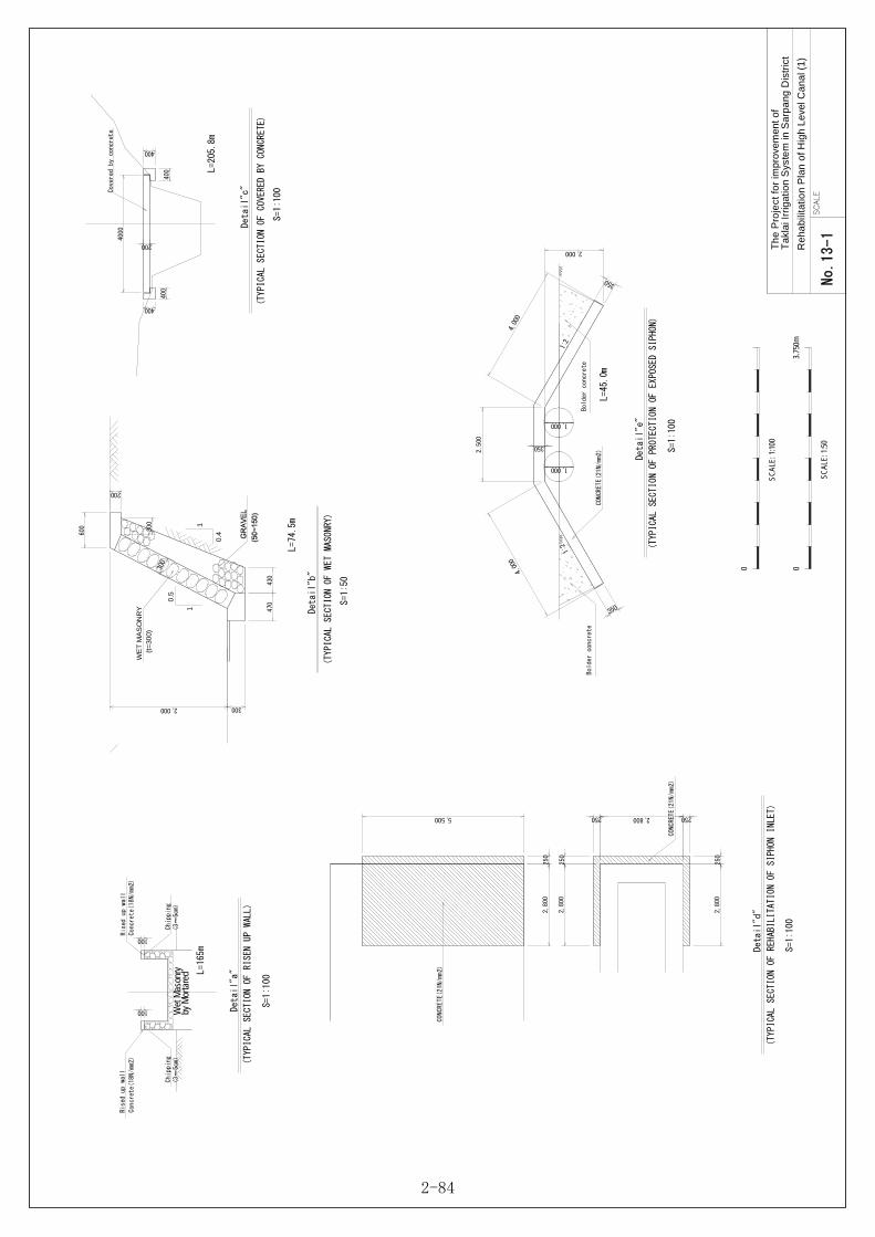
Tak
lai I
rrig
atio
n S
yste
m in
Sar
pang
Dis
tric
t T
he
Pro
ject
for
impr
ovem
ent o
f
Re
habi
litat
ion
Pla
n o
f Hig
h Le
vel C
anal
(1)
0
SCAL
E: 1
:50
3.75
0m
0
SCAL
E: 1
:100
Detail"a"
S=1:100
(TYPICAL SECTION OF RISEN UP WALL)
Ris
ed up wall
100
100
Chipping
(3~
5cm)
Chipping
(3~
5cm)
600
200
300
0.5
1
0.4
1
WE
T M
AS
ON
RY
(t
=30
0)
Detail"b"
S=1:50
(TYPICAL SECTION OF WET MASONRY)
Detail"c"
S=1:100
(TYPICAL SECTION OF COVERED BY CONCRETE)
4000
200
400
400
400
400
Covered by concrete
2,800
250
250 2,800 250
Detail"d"
S=1:100
(TYPICAL SECTION OF REHABILITATION OF SIPHON INLET)
2,800
250
2,800
250
5,500
2,500
2,000
4,000
4,000
350
350
350
Detail"e"
S=1:100
(TYPICAL SECTION OF PROTECTION OF EXPOSED SIPHON)
CONCRETE(21N/
mm2)
CONCRETE(21N/mm
2)
1,000
1,000
Concrete(18N/mm2)
Con
crete(18N/mm2)
Rised up wall
L=165m
L=74.5m
L=205.8m
CON
CRETE(21N/mm2)
L=45.0m
470
430
2,000 300
1:2
1:2
300
by M
orta
red
Wet
Mas
onry
Bolder concrete
Bolder concre
te
No.13-1
2-84

7.50
0m
B
H
Gate Leaf
Guide Frame
Spindle(φ
50)
Cover Concrete
Detail"f"
S=1:100
(TYPICAL SECTION OF CHECK GATE)
NO.
BH
C.G 5
1.95m
1.40m
REMARKS
Replace
C.G 9
1.95m
1.20m
Replace
C.G 1
Install
C.G 11
1.00m
0.50m
Replace
Install
Len
ght
ofGuide frame
12.1m
11.3m
5.2m
H
B
Spindle(φ
35)
Guide Frame
Gate Leaf
500
H
1:1
1:1
200
1:1
1:1
H
NO.
BH
D.G 2
0.50m
1.50m
REMARKS
Replace
D.G 10
0.70m
1.55m
Replace
Lenght of
Guide frame
7.6m
8.5m
D.G 13
0.70m
1.35m
Replace
7.7m
Detail"g"
S=1:100
(TYPICAL SECTION OF DISTRIBUTION GATE)
Tak
lai I
rrig
atio
n S
yste
m in
Sar
pang
Dis
tric
t T
he
Pro
ject
for
impr
ovem
ent o
f
0
SCAL
E: 1
:50
3.75
0m
0
SCAL
E: 1
:100
7.50
0m
0.85m
0.70m
5.5m
New
3,000
2,000
Chipping and Plas
ter(18N/mm2)
50
Detail"h"
S=1:100
(TYPICAL SECTION OF REHABILITATION OF CROSS BRIDGE)
50
50
500
1.95m
1.20m
11.3m
W
B
L30×30×4
L30
×30×
4
D12@100
Location
WB
1st Siphon Inlet
3.50m
3.10m
3.50m
3.10m
2.30m
1.70m
2.70m
1.90m
2.30m
1.70m
Detail"i"
S=1:50
(TYPICAL SECTION OF SAFETY SCREEN)
@600
1st Siphon Outlet
2nd Siphon Inlet
2nd Siphon Outlet
3rd Siphon Inlet
3rd Siphon Outlet
2.90m
2.50m
Re
habi
litat
ion
Pla
n o
f Hig
h Le
vel C
anal
(2)
L=50.0m
C.G 2
New
No.13-2
2-85

00-0Tak
lai I
rrig
atio
n S
yste
m in
Sar
pang
Dis
tric
t T
he
Pro
ject
for
impr
ovem
ent o
f
Re
habi
litat
ion
Pla
n of
Sip
hon
Plan S=1:100
FLOW
Crac
k
Pla
tePl
ate
Roa
d
Contracti
on Joint
(Painting)
Concr
ete Saddle
300
2,700
300
1,000
Reinforced Concrete Sec
tion
3,300
Plain Concrete Section
4,000
Low
Leve
l Ca
nal
(Exi
sti
ng C
ana
l)
Siphon
φ600 Ca
st Iron Pipe
C L
100600
2,100
600
100
1,050
1,050
≒1,030
1,350
1,350
300
2,700
300
2001003001,200
3001,500
200600200
1001,000
100
AA
BB
CC
Concrete Sadd
le
Supporting Beam
(I-200×
140×
9×6.1)
Low Lev
el Canal
(Existing Canal)
Section A-A
S=1:100
Leveling Concrete
Gravel(0~
40mm)
Reinforced
Concrete Section
3,300
Plain Concrete Section
4,0
00
Roa
d
Deta
il a
Siphon
φ600 Cast I
ron
Pipe
0
SCAL
E: 1
:50
3.75
0m
0
SCAL
E: 1
:100
7.50
0m
Rehabilitation Pl
an of
the Siphon
S=1:100
C L
1,6
50
375
Canal Width 3,150
375
300
3,900
300
Detail-a
A A
Profile Bridge
S=1:100
4,500
200
100
600
100
600
100
800
Lev
eling Concrete
Gravel(0~
40mm)
Expansion Joint
Elastic Filler(t=20)
Expansion Joint
Elastic Filler(t=20)
20
20
3,860
Layout of Handrail
S=1:50
3,860
300300400400
600800
130
900×
4=3,600
130
150
B B
C L
300
4,000
300
300
1,6503001,100
Canal Bottom
Handrail
Secti
on A-A
S=1:100
300
150
800
Bea
m(F-
50×6×L=4
,050)
Strut @1,000
Slab of Bridge
(L-50×6×
L=950) Section B-B
S=1:50
400400
800 600
1,400
4,600
Impro
vement Plan of t
he Cross Bridge
on Can
alS=1:100
No.13-3
2-86
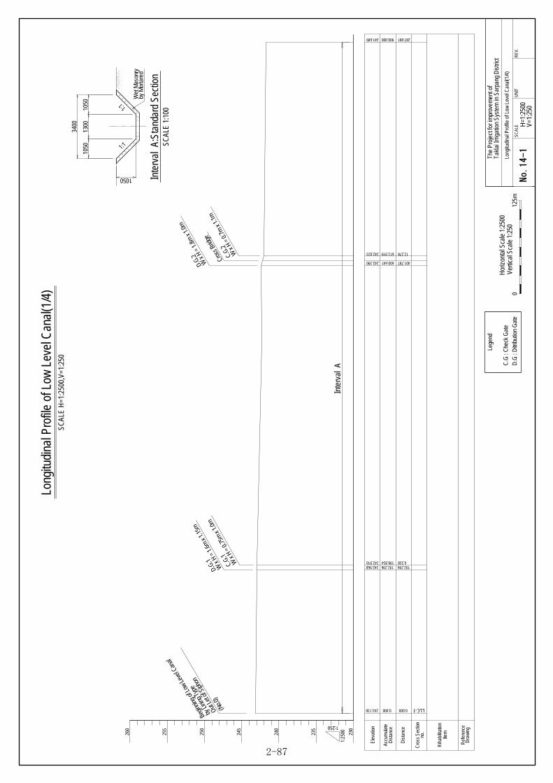
Accu
mul
ate
Dis
tanc
e
Cro
ss S
ectio
nno
.
Dis
tanc
e
Ref
eren
ceD
raw
ing
Rih
abilit
atio
nIte
m
SCAL
E H
=1:2
500,
V=1:
250
Long
itudi
nal P
rofil
e of
Low
Lev
el C
anal
(1/4
)
235
240
245
250
255
260
230
243.130
242.968242.910
242.390
242.023
0.000
192.296198.854
600.641
612.919
Cros
s Brid
ge
LLC-1
1:25
00
1:250
0.000
192.2966.558
401.787
12.278
Hor
izon
tal S
cale
1:2
500
Verti
cal S
cale
1:2
500
125m
Dra
win
g No
. 03-1
SCAL
EU
NIT
REV
.
Takl
ai Ir
rigat
ion
Syst
em in
Sar
pang
Dis
trict
H=1
:250
0V=
1:25
0
The
Proj
ect f
or im
prov
emen
t of
Long
itudi
nal P
rofil
e of
Low
Lev
el C
anal
(1/4
)
Elev
atio
n
(No.0
)by
Linin
g Typ
e
Begin
ning o
f Low
Leve
l Can
al
Out L
et of
Siph
on
D.G.
1
W x
H =
1.6m
x 1.
15m
C.G.
1
W x
H =
0.75
m x 1
.0m
D.G.
2
W x
H =
1.8m
x 1.
0m
Lege
nd
C.G
: C
heck
Gat
eD
.G :
Ditr
ibut
ion
Gat
e
C.G.
2
W x
H =
0.7m
x 1.
1m
241.689 900.000 287.081
Inte
rval
A:S
tand
ard
Sect
ion
SCAL
E 1:
100
1050
1300
1050
3400
1050
by M
orta
red
Wet
Mas
onry
Inte
rval
A
1:1
1:1
No.14-1
2-87

Accu
mul
ate
Dis
tanc
e
Cro
ss S
ectio
nno
.
Dis
tanc
e
Ref
eren
ceD
raw
ing
SCAL
E H
=1:2
500,
V=1:
250
Long
itudi
nal P
rofil
e of
Low
Lev
el C
anal
(2/4
)
235
240
245
230
225
241.573 1000.000
240.594 1500.000
241.540 1007.997
241.480 1019.333
241.090 1189.811
240.915 1241.209
Cros
s Brid
ge
LLC-2
LLC-3
1:25
00
1:250
387.081
138.791
7.997
11.336
170.478
51.398
Hor
izon
tal S
cale
1:1
:250
0Ve
rtica
l Sca
le 1
:250
012
5mDr
awin
g No
. 03-2
SCAL
EU
NIT
REV
.
Takl
ai Ir
rigat
ion
Syst
em in
Sar
pang
Dist
rict
H=1
:250
0V=
1:25
0
The
Proj
ect f
or im
prov
emen
t of
Long
itudi
nal P
rofil
e of
Low
Lev
el C
anal
(2/4
)
Elev
atio
n
Lege
nd
C.G
: Ch
eck
Gat
eD
.G :
Ditri
butio
n G
ate
241.689 900.000 287.081
240.875 1800.000 135.990
240.260 1664.010
Cros
s Brid
ge
164.01
D.G.
3
W x
H =
0.7m
x 1.
05m
C.G.
3
W x
H =
1.5m
x 1.
3mD.
G.4
W x
H =
1.65
m x 1
.1m
C.G.
4
W x
H =
0.9m
x 1.
1m
D.G.
5
W x
H =
0.6m
x 0.
7m
Inte
rval
A
Inte
rval
A:S
tand
ard
Sect
ion
SCAL
E 1:
100
1050
1300
1050
3400
1050
by M
orta
red
Wet
Mas
onry
1:1
240.790 1341.209 100.000
240.766 1361.209 20.000
Rih
abilit
atio
n W
all
L=20
.00m
Rih
abilit
atio
nIte
m
1:1
250
No.14-2
2-88
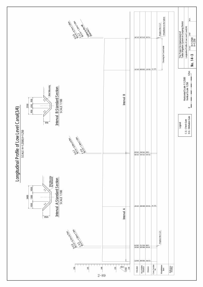
Accu
mul
ate
Dis
tanc
e
Cro
ss S
ectio
nno
.
Dis
tanc
e
Ref
eren
ceD
raw
ing
SCAL
E H
=1:2
500,
V=1:
250
Long
itudi
nal P
rofil
e of
Low
Lev
el C
anal
(3/4
)
250
245
235
240
239.967 2000.000
240.025240.010 1855.732
239.900 2193.343
239.820 2196.943
1849.244
LLC-4144.268
49.2446.488
193.343
3.600
1:25
00
1:250
Hor
izon
tal S
cale
1:1
:250
0Ve
rtica
l Sca
le 1
:250
012
5mD
rawi
ng N
o. 03-3
SCAL
EU
NIT
REV.
Takl
ai Ir
rigat
ion
Syst
em in
Sar
pang
Dist
rict
H=1
:250
0V=
1:25
0
The
Proj
ect f
or im
prov
emen
t of
Long
itudi
nal P
rofil
e of
Low
Lev
el C
anal
(3/4
)
Elev
atio
n
Lege
nd
C.G
: C
heck
Gat
eD
.G :
Ditr
ibut
ion
Gat
e
239.570 2500.000 LLC-5303.057
239.298 2616.246 116.246
230
240.875 1800.000 135.990
D.G.
6
W x
H =
0.7m
x 0.
75m
C.G.
5
W x
H =
1.35
m x
1.0m
D.G.
7
W x
H =
0.9m
x 0.
9m
C.G.
6
W x
H =
1.4m
x 1.
0mD.
G.8
W x
H =
0.7m
x 1.
05m
C.G.
7
W x
H =
1.2m
x 1.
0m
Inte
rval
AIn
terv
al B
Inte
rval
A:S
tand
ard
Sect
ion
SCAL
E 1:
100
1050
1300
1050
3400
1050
950
650
950
2550
950
1:1
1:1
Inte
rval
B:S
tand
ard
Sect
ion
SCAL
E 1:
100
by M
orta
red
Wet
Mas
onry
Wet
Mas
onry
Rih
abilit
atio
nIte
m
Rep
lace
the
C.G
.5
Cle
anin
g fo
r Can
al in
side
(from
HLC
)Si
phon
to th
e Hi
ll
Rep
lace
the
C.G
.7
Rih
abilit
atio
n to
the
Siph
on
1:1
1:1
No.14-3
2-89

Accu
mul
ate
Dis
tanc
e
Cro
ss S
ectio
nno
.
Elev
atio
n
Dis
tanc
e
Ref
eren
ceD
raw
ing
SCAL
E H
=1:2
500,
V=1:
250
Long
itudi
nal P
rofil
e of
Low
Lev
el C
anal
(4/4
)
250
245
240
233.860 2901.061 LLC-6
230
235
284.815
1:25
00
1:250
Hor
izon
tal S
cale
1:1
:250
0Ve
rtica
l Sca
le 1
:250
012
5mD
raw
ing
No. 03-4
SCAL
EUN
ITR
EV.
Takl
ai Ir
rigat
ion
Syst
em in
Sar
pang
Dist
rict
H=1
:250
0V=
1:25
0
The
Proj
ect f
or im
prov
emen
t of
Long
itudi
nal P
rofil
e of
Low
Lev
el C
anal
(4/4
)
Lege
nd
C.G
: C
heck
Gat
eD
.G :
Ditr
ibut
ion
Gat
e
237.699 2700.000 83.754
Inte
rval
C
1200
1:0.5
750
Inte
rval
C:S
tand
ard
Sect
ion
SCAL
E 1:
100W
et M
ason
ry
1:0.5
Rih
abilit
atio
nIte
m
375
450
375
239.298 2616.246 116.246
D.G.
8
W x
H =
0.7m
x 1.
05m
C.G.
7
W x
H =
1.2m
x 1.
0m
(from
HLC
)Si
phon
to th
e Hi
ll
Rep
lace
the
C.G
.7
Rih
abilit
atio
n to
the
Siph
on
600
200
WET
MAS
ON
RY
(t=30
0)
S=1:
100
REH
ABIL
ITAT
ION
OF
WET
MAS
ON
RY
L=20
.0m
1050 300
1
1
B
H
Gui
de F
ram
eS
pind
le(φ
50)
Cov
er C
oncr
ete
S=1:
100
NO
.B
H
C.G
51.
35m
1.00
m
REM
ARKS
Rep
lace
C.G
71.
20m
1.00
mR
epla
ce
Leng
ht o
fG
uide
fram
e
8.4m
7.4m
500
H
1:1
1:1
TYPE
OF
REP
LAC
E G
ATE
Gat
e le
af
SCAL
E 1:
100
Reh
abilit
atio
n Pl
an o
f Stru
ctur
e
No.14-4
2-90

00-0Tak
lai I
rrig
atio
n S
yste
m in
Sar
pang
Dis
tric
t T
he
Pro
ject
for
impr
ovem
ent o
f
Impr
ove
men
t Pla
n o
f E
xist
ing
Con
fluen
ce
Mas
onry
wa
ll
LLC
.S -0
2
Lin
k ca
nal
Gabio
ns
(New Construction)
Retaining Wall (N
ew Construction)
(to see "Detail Plan")
A
A
EL 246.92
EL 245.15
C L
▽EL 247.45
EL 245.70
3,000
4,650
7,650
550
1,750
Retaining Wall (N
ew Construction)
(to see "Detail-a,b")
Set Gabion
(New Construction)
Secti
on A-A
S=1:200
Impro
vement Plan of E
xisting Confluen
ceS=1:200
4,000
650
3,000 7,6
50
500
500
250
500
1,250
1,750 2,5
00
750
2,0002,650
4,650
1,500
800
100
500500
1,000
700
Detai
l Plan of Retain
ing Wa
llS=1:100
Handrail
(to see "Detail-g")
Gate Opening
(to see "Detail-c~f
")
aFLOW
a
b b
Deta
il a-a
S=1:100
500
500
500
1,100
800
1,750
250
200100250
250
700×
700800
6001,150
3002,000
100
1,500
100
250
1,250
1,750
GL 245.70
EL
247.
45
Handrail
Spindle
Guide Frame
Lean Concrete
Grave
l(0~
40mm)
FLOW
Gate Leaf
Opening
▽EL 246.30
Detail b-b
S=1:100
Spindle
Guide Fra
me
Lean Concrete
Gravel(0~
40mm)
Handrail
2,650
2,000
100
4,650
100
200100
2501,750
3002,0001,100
700
2,150
1,000
1,500
700800
Detail-g(Handrail)
S=1:50
250
150
1,100
550550
100
Beam(F-
50×6)
Strut(L-50×
6)@<1.0m
Operation Slab
(Rein
forced Concrete)
Detail-c(
Layout
of Guide Frame)
S=1:50
Spindle
φ35
Guide Frame
(C-75×40×
4.4×
7.3)
EL 247.45
Operation Slab
Cover Concrete
Gate Leaf
▽EL 245
.70
dd
Botto
m Slab of Retaining Wall
2502501,250250800
700
700
200
700
200
1,100
200250
FLOW
Wall
Cover Concrete
Guide Frame
(C-75×40×
4.4×
7.3)
Detail d-d
S=1:50
Detail-
e(Gate Leaf)
S=1:50
Main Beam
(L-50×
6)
Sub Beam
(F-
50×6)
380
380
W=760
H=730
f f
L-50×
6
F-5
0×6
FLOW
L-5
0×6
Rubber Seal
(W=30mm @all side)
H=730
Skin Plate
(t=
6mm)
Detail f-f
S=1:40
0
SCAL
E: 1
:100
3.75
0m
0
SCAL
E: 1
:50
1.87
5m
0
SCAL
E: 1
:40
1.50
0m
0
SCAL
E: 1
:200
7.50
0m
2,000
4,650
500
2,000
Demolition of Existin
g Wall
3,500
650
200100250
100
Lean Concrete
Grave
l(0~
40mm)
2,6
502,000
FLOW
3,000
7,650
No.15
2-91

2-2-4 Implementation Plan
2-2-4-1 Implementation policy
(1) Basic item
The implementation of this Project is to be executed in the institutional framework of Japanese grant
aid. After completing overall design, provided that the said implementation is approved by Japanese
government, an Exchange of Notes (E/N) will be exchanged between the governments of both country
to shift to the Project implementing stage. The type of lump some contract is applied to the contract for
Project implementation.
In this Project, it is planned to construct integrated head works, head race, link canal, high level main
canal, low level main canal, embankment at downstream etc and to reinforce the existing gabion
revetment.
(2) Employment of local constructors
At present, local constructors exist that are run by local people, but no constructor by foreign capital
investment is found in Bhutan. As to local constructors, most of them have small-scaled ones, but
some are large-scale ones that extend their business activities mainly in the capital city, Thimphu,
holding a lot of construction machinery. However, their past performances have largely been limited in
narrow domains of work including road construction, wet masonry and revetment such as gabion
layers with poor performances on the construction of concrete structures. Accordingly, it is only
Location map of construction work on Taklai Irrigation System
Fig 2-24:Location map of construction work on Taklai Irrigation System
2-92

possible to utilize local constructors to perform a part of the construction work scheduled under this
Project including wet masonry, gabion laying etc.
(3) Necessity of dispatching engineers
Engineers and skilled workers who have sufficient knowledge and technical skill on construction work
are very few in Bhutan. To cope with such a situation, it is planned to dispatch civil work engineers
and mechanic engineers in this construction work. At the same time, it is also planned to dispatch
skilled workers to ensure the required accuracy of the work for the provision of welding, and
installation of machinery, so as to perform the designed work under the construction system with the
initiative of skilled persons.
(4) Executing system at Bhutan’s side
As far as this Project is concerned, the Project executing agency of Bhutan side, namely, Engineering
Division (ED) of Department of Agriculture (DoA) of Ministry of Agriculture and Forestry will be
responsible for the overall management of the Project, and also the local office of Central Machinery
Unit (CMU) under DoA, that of Research and Development Center (RDC), district and county offices
concerned are to participate in the Project implementation with their role-sharing.
Central
Engineering Division,
The Department of Agriculture
Project Manager
RDC
Bhur
CMU
Bhur
District
Administration
Geog
Administration
Consultant
Central
Function and Roles
Project
management and
coordination
Agricultural
research and
extension
Support WUA
regarding O&M
Function and Roles
Major
maintenance
Function and Roles
Field coordination
Project related
clearances
Security
Extension service
Stakeholder
meetings
Function and Roles
Overall Management and Coordination
of the Project
Approval on Project Implementation
Function and Roles
Field coordination
Project related
clearances
Land issues
Community
meetings
Function and Roles(Consultant)
Detailed Design
Construction supervision
Assist in Project management
Contractor
RDC: Research and Development Centre
CMU: Central Machinery Unit
WUA: Water Users Association
Project Site
Fig 2-25:Organization for the Project Implementation
2-93

2-2-4-2 Implementation conditions
(1) Attentions to be paid on the work
1) Work of head works
The construction of head works is worked in the river. Because the planned site is surrounded by
mountains it is difficult to perform the work in the lump by coffering the entire river bed. By this
reason, the construction of this facility is designed by the method of partial coffer controlling half of
the river flow with large sized sand-bags. Water sprung into the coffer is drained by submerged pumps
with a diameter φ200m (5 pumps are mobilized).
The existing maintenance road for facility management at the mountain side of the head race is used
for the entrance of vehicles for construction work and carriage of equipment/ materials, and another
access road for construction is ensured inside the river along the right side bank since flow center line
of the river in dry season runs along left side bank.
Because the scale of head works section is large, requiring large quantity of concrete to be cast per
one time of casting, thus casting work is performed by a crane commuted from the construction yard.
On the other hand, revetment blocks are provided by cast-in-place.
2) Work of culvert section of head race
The whole section of head race ranges from the head works to the inlet of first siphon at high level
main canal. Out of this section, the sub-section of about 390m from the head works consists of culvert
with steel-reinforced concrete. The planned work for head race consists of concrete work, installation
of concrete blocks gabion to the river-side and gabion layer to the excavated hill-side.
In this concern, while large amount of excavated earth is generated from the work in culvert section,
it is planned to spoil the excavated earth by carrying it with damp-trucks to the spoil yard in river-bed
around the front of the existing gabion revetment at the right bank, at downstream side of the work site.
As to the spoil yard, it has already been consulted and agreed with the counterpart organization,
however, it will again be identified with the counterpart just prior to the initiation of the work.
3) Work of open canal section of head race
Out of the total section of the head race, about 540m is the section of open canal, and out of this
section, about 170m is designed to make it reinforce concrete structure as a newly constructed section
and the existing canal section is planned to be utilized as it is for the rest of around 370m.
Nevertheless, the existing canal has to be improved by stripping off the vulnerable/ degraded part and
plain concrete is cast (t = 20cm) over the bottom floor and flank wall. In this case, concrete is planned
to be manually cast.
4) Reinforcing work for the existing gabion revetment
The planned reinforcing work for the existing gabion revetment comprises to fill back-filling
2-94

material in front of the existing structure and to install concrete revetment. In constructing this
revetment, back-hoes are used for floor excavation and concrete is cast by a crane. In this work,
gabion is laid as foot protection work in front of the revetment.
5) Work of high level main canal
Work of high level main canal consists of repair work of wet masonry revetment along the canal,
heightening of flank wall beside the canal to cope with shortage in flow section, installation of cover
concrete to prevent stones dropping from rock mass to the canal, repair of leaking part in the existing
siphons, protective work covering the exposure of the existing siphons, repair work at leakage from
the existing aqueduct, rehabilitation of a dilapidated bridge traversing over the canal, exchanging
dilapidated check-gates/ diversion gates and installation of fences to prevent falling down.
・Heightening of flank wall of the canal and repair of wet masonry
Work of heightening flank wall of the canal covers the section of 165m downstream of the
outlet of the first siphon. In this work, surface of the existing wall is stripped off about 5m
thick and cast plain concrete over the stripped part with the heightening height of 10cm by
manual casting. At the same time, the broken section of wet masonry about 75m long located
adjacent to the site of heightening is repaired to the original structure.
・Cover concrete
Cover concrete to prevent stones dropping down to the canal is to be installed over the section
about 205m starting from the outlet of first siphon to downstream. Timbering is assembled
inside the canal and reinforced concrete is cast by manual work.
・Protective work for the part of exposure of the siphon traversing beneath a river (third siphon)
Because a part of the pipe is left exposed, the part is covered with about 35cm thick plain
concrete. In this work, excavated parts at upstream side and downstream side are refilled with
boulder concrete for preventing scouring.
・Repairing work over the broken part of conveyance siphon to an upland
Conveyance siphon to an upland is made of cast-iron. Because the tube has been cracked, the
parts of fissures are closed by welding iron sheets then the entire pipe is lined with reinforced
concrete to withstand inner water pressure, thus preventing further cracking /breakage.
・Repair of leaking parts
For repairing light leakage, mortar concrete is plastered over the leaking parts. In the case of
escalated leakage, the parts are repaired by casting plain concrete from the outside of the
structure.
・Canal traversing bridges
2-95

Two canal traversing bridges with their length and width of about 4m are to be renewed by
removing them and newly reconstructing those with concrete floor at the same locations as
they are now.
6) Work of link canal
Since the canal has wet masonry structure, heightening of the flank wall beside the existing canal by
around 20cm is worked by wet masonry, accompanied with the heightening of the bottom floor inside
the canal by about 10cm (for adjusting canal gradient) that is worked with plain concrete.
7) Work of low level main canal
The existing structure is fully made use of for constructing confluence works at the starting point of
the canal(confluence point with link canal)utilizing L-shaped revetment made of reinforced concrete
that closes necessary parts.
8) Downstream embankment work
Construction/ compaction is worked by bulldozers for the downstream embankment work, by
installing concrete leaning wall as flood protection, laying gabion at its crest and rear, river-side to
prevent erosion by unexpected overflowing flood flow. In constructing retaining wall, floor is
excavated with back-hoes and concrete is cast by crane. In this work, gabion is laid in front of
retaining wall as foot protection.
(2) Items to be regarded for procurement
It is conceived that Bhutanese laborers are employed in Gelephu and around the Project site.
However, they have been oriented in a construction rush to the sites of constructing hydro-power
generation dams and other facilities, so procuring laborers becomes exceedingly difficult especially
during peak cropping season. This situation would lead to the necessity of hiring laborers from remote
areas.
2-2-4-3 Scope of works
The following shows the division of cost sharing between Japanese side and Bhutanese side in carrying
out this plan.
2-96

Table 2-32: Cost-sharing division of construction, procurement and installation
Japanese side Bhutanese side ① Integrated headworks: 1 set
・Fixed weir: 38.9m long x 1.0m high ・Downstream bed pitching work: with concrete cross-shaped blocks
8t・coupled paving, length: 27.6m ・Water gauge: 1 set of ultrasonic type
② Headrace: 1 set ・Culvert section: width:1.5m x height:1.0m x total length 358.9m ・Open Canal section: width: 2~3.5m x height: 0.5~3.2m x total
length 631.2m ・Sedimentation basin width: 3.5~7.85m x height 0.5~1.5m x total
length 37.5m ③ Reinforcement of the existing gabion revetment: 1 set ・Concrete leaning wall: height: 3.9m x total length 410m
④ Link canal: 1 set ・section of heightening: Max. heightening 0.36m x total length 654.6m ・section of the entire renewal construction: total length 109.6m
⑤ High level main canal: 1 set ・ Rehabilitation of wet masonry revetment : total length: 123.7m ・ Canal heightening: heightening height: 0.1m x total length: 165m ・ Concrete covering: total length: 205.8m ・ Mending leakage of siphons: increased thickness by reinforced
concrete 8.4m x height 5.5m.x thickness: 0.25m ・ Protection for exposed siphon pipe: total length: 45m ・ Mending leakage from aqueduct: total length: 50m ・ Installation of check gates/ diversion gates: 10 gates ・ Installation of fence to prevent falling down: 6 sites ・ Repair of broken part in siphons: lining with reinforced concrete: 1
set ・ Renewal of canal traversing bridges: 2 bridges with concrete paved
floor: (width and length: both 4m) ⑥ Low level main canal: 1 set
・ Rehabilitation of wet masonry revetment: total length: 20m ・ Check gate installation: 2 gates ・ Conffluence works: L-shape retention wall height: 2m x total length
4.7m, newly constructing gate: 1 gate ⑦ Downstream embankment: 1 set
・Concrete leaning wall : height: 3.9m x total length 340m ・ Embankment construction: width of the crest: 4.0m x height: 3.0m x
total length 340m ⑧ Provision of software component on facility operation, water
management, O/M 1 set
① To procure construction site ② Free of charge provision of land area/ borrowed
places to be used for construction work ③ Repair of access rod to the planned construction site,
notification of information on the scheduled utilization of the existing roads to local inhabitants during construction period
④ Clearance of the official requesting procedures to be submitted to and approved by offices concerned on cutting of tree stands, collection of material aggregates from river floor etc.
⑥ Extension of electric wire cable to the site managing office.
⑦ Assignment of (2 persons of) counterparts in charge in providing software component
2-2-4-4 Consultant supervision
(1) Basic principles, Attention to be paid
In performing construction supervision under this plan, attention on the following items is to be
paid:
1) Basic principles
a) To be acquainted and conscious with the contents and background of overall design and
detailed design,
b) To understand the mechanism/ system of the Grant Aid Cooperation Project,
c) To grasp the contents of Exchange of Notes(E/N)and Grant Agreement(G/A)agreed
between both countries,
2-97
d) JICA strives for smoothly promote in collaboration with the executing agency of
Bhutanese side, namely, Engineering Division (ED) of Department of Agriculture (DoA)
of Ministry of Agriculture and Forestry, Central Machinery Unit (CMU), Research and
Development Center (RDC), local administration office and District and Geog office.
e) Items to be borne by Bhutanese side agreed on in the occasion of Overall Design will
again be re-identified with Bhutanese side.
2) Attention to be paid on construction management
a) Process management
i) To identify such required procedures as custom clearance, measures on import tax
exemption accompanying with importing/ carrying in equipment/ machinery etc, and to
consult with local executing agencies including Engineering Division (ED) of
Department of Agriculture (DoA) of Ministry of Agriculture and Forestry, Central
Machinery Unit (CMU), Research and Development Center (RDC), local administration
office and District and Geog office so as not to influence on the progress of work within
construction period.
ii) Climate in Sarpang district is divided into rainy season (flooding period: 4 months, June
~ September) and dry season (8 months October ~ next May). Access route to the
Project site has several points of traversing streams on the way where traffic becomes
impossible during rainy season, thus the construction period of a dry season is
determined the period from October to next May. In this connection, since October and
May have more rainfall than other dry-season months, it is planned that earth work /
concrete work is avoided during these months as much as possible. Quality management
iii) Careful attention is to be paid to atmospheric temperature and working conditions so as
to secure quality of concrete.
b) Safety
i) To keep safety management during the construction period so that traffic accident and
electric shock accident are not happened.
ii) To establish an emergency communication network.
c) Documents
i) To properly manage such documents as drawings of approbation, construction drawings,
completion drawings, inspection records, reports on the progress of work etc.
2-98
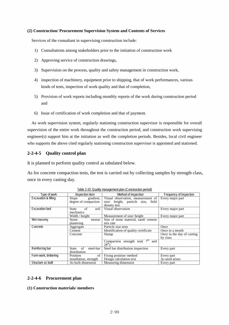
(2) Construction/ Procurement Supervision System and Contents of Services
Services of the consultant in supervising construction include:
1) Consultations among stakeholders prior to the initiation of construction work
2) Approving service of construction drawings,
3) Supervision on the process, quality and safety management in construction work,
4) inspection of machinery, equipment prior to shipping, that of work performances, various
kinds of tests, inspection of work quality and that of completion,
5) Provision of work reports including monthly reports of the work during construction period
and
6) Issue of certification of work completion and that of payment.
As work supervision system, regularly stationing construction supervisor is responsible for overall
supervision of the entire work throughout the construction period, and construction work supervising
engineer(s) support him at the initiation as well the completion periods. Besides, local civil engineer
who supports the above cited regularly stationing construction supervisor is appointed and stationed.
2-2-4-5 Quality control plan
It is planned to perform quality control as tabulated below.
As for concrete compaction tests, the test is carried out by collecting samples by strength class,
once in every casting day.
Table 2-33: Quality management plan (Construction period)
Type of work Inspection item Method of inspection Frequency of inspection Excavation & filling Slope gradient,
degree of compactionVisual observation, measurement of size/ height, particle size, field density test
Every major part
State of soil mechanics
Visual observation Every major part Excavation bed
Width / height Measurement of size/ height Every major part Wet masonry Stone. mortar
plastering Size of stone material, sand/ cement mix rate
Aggregate Particle size tests Once Cement Identification of quality certificate Once in a month
Slump Once in the day of casting by class
Concrete Concrete
Compaction strength test( 7th and 28th)
Reinforcing bar State of steel-bar distribution
Steel bar distribution inspection Every part
Form work, timbering Position of installation, strength
Fixing position/ method Design calculation text
Every part As need arises
Structure as built As built dimension Measuring dimension Every part
2-2-4-6 Procurement plan
(1) Construction materials/ members
2-99

Domestic procurement of most general construction materials such as reinforcing bar etc is available
in Bhutan. They are planned to be procured from Phuntsholing, central marketing place where
construction materials are collected and accumulated. The following table shows division of procuring
major construction materials/ members.
Table 2-34: Division of procuring construction materials
Destination for procurement Name of materials/ members
Bhutan Japan Third country Remarks
Fine & coarse aggregates ○
Normal Portland cement ○ Difficult to procure in local market
Reinforcing bar ○ Earth filling material ○ Riprap, Masonry stone for wall ○ Crashed stone ○ Steel scaffold material ○ Veneer form ○ Diesel oil ○ Gasoline ○ Gabion ○ Gate materials ○
Water stop ○ Difficult to procure in local market, quality is regarded
Expansion joint ○ Difficult to procure in local market, quality is regarded
Rail ○ Large sacks for sand bags ○
(2) Major construction machinery
Rough terrain, concrete mixer car, crusher plant and batcher plant are not available in Bhutan, they
are procured in the third country(India) to be used in this Project.
Table 2-35: Table of procurement division
Division of procurement Type Name of Machinery Bhutan Third country
Remarks
Back hoes ○ Crawler type,0.13m3 class, 0.28 m3 class, 0.45 m3 class, 0.8 m3 class
Bulldozers ○ 15t class, 20t class Damp trucks ○ 10t loading Crane truck ○ 4t loading 2.9t hoisting Raough terrain crane ○ 16t Vibration roller ○ 0.8-1.1t class, 3-4t class Batcher plant ○ 30 m3/h Crasher plant ○ 50 m3 /day Concrete mixer car ○ 5 m3
Construction m
achinery directly used in the construction w
ork
Dynamo generator ○
(3) Carriage route
Machinery and equipment procured in Japan is transported from Japan to Calcutta Port by marine
transport, and after landing there, they are transported via Phuntsholing in Bhutan where custom office
is located, to the site in Sarpang District by truck.
2-100

On the other hand, domestic materials procured from Phuntsholing where domestic construction
materials are collected, are carried on land along the route through Thimphu and Wangdue.
Machinery and equipment also procured in India is carried on the same route from Phuntsholing.
2-2-4-7 Operational guidance plan
Basic information (supplier, detail drawing as built, etc) of newly constructed and renewed gates is
submitted Bhutan side from the Contractor, and detail method of operation and maintenance is
instructed Bhutan side from the Consultant.
2-2-4-8 Soft component (technical assistance) plan
(1) Background of planning soft components
The target facilities to be constructed in this Project as main ones covering the Project area (target
irrigation area 1,120ha) consist of (1) new construction of the integrated headworks (including river water
gauge), (2) new construction and rehabilitation of the head race, (3) reinforcing work of the existing gabion
revetment, (4) repair of the main canal (high level canal/ low level canal/ link canal) and (5) protection
works for farmland erosion (river dike). Operation and maintenance of main facilities targeted in this
Project out of the above-listed facilities are currently carried out by RDC/ CMU that is a subordinate
organization of Engineering Division (ED) in Department of Agricultural (DoA) of Ministry of Agriculture
and Forests, while that of the secondary and minor ones are managed by Water Users Associations (WUA)
of Chuzagang Geog and Sershong Geog supported by RDC Bhur engineer that have been organized in
2001.
To realize the above-mentioned Project goals in a sustainable manner, long-term utilization of the
irrigation facilities as well as equitable and proper water allocation are essential. To this end, though
the currently existing facilities have been managed by the above cited organizations by conventional
adopted method, they have been suffering from constraints/ issues of ① insufficient knowledge for
formulating plan of facility operation and maintenance and poor technical know-how to securely put
the plan into practice, ② retarded environment to train water management technicians for
accelerating effective/ rational utilization of irrigation water. Therefore, technical support by soft
component is planned to solve these issues, in addition to the rehabilitation of the existing facilities.
(2) Target of soft components
In the light of current state of facility operation and management activities as well as water
management, on the premise of that the Bhutanese side is continuously engaged in the improvement
activities even after the completion of this Project, the soft component is planned aiming at a goal;
“the stakeholders learn and master necessary knowledge for operation and maintenance of the newly
constructed and rehabilitated irrigation facilities as well as water management”.
(3) Output of soft components
Targeted output obtained by accomplishing the above mentioned goal is expected as “improved
2-101
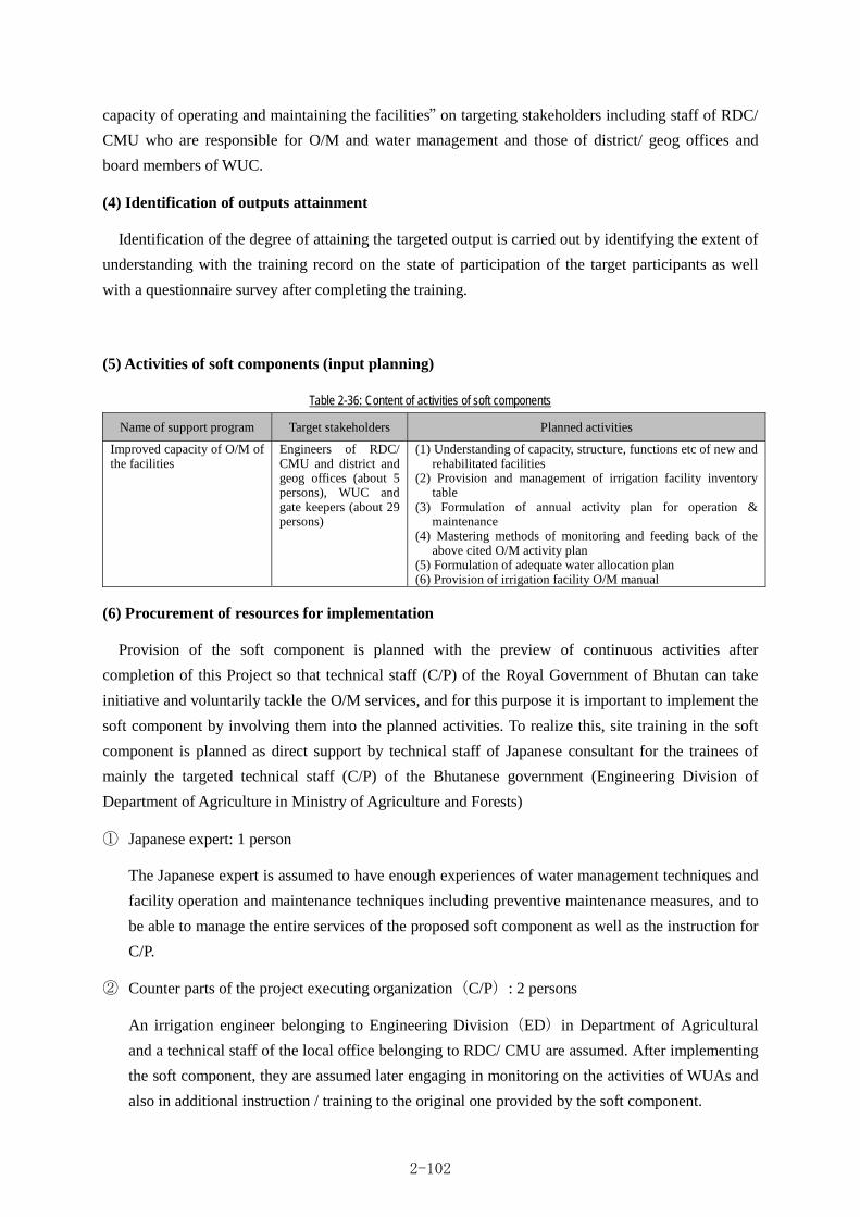
capacity of operating and maintaining the facilities” on targeting stakeholders including staff of RDC/
CMU who are responsible for O/M and water management and those of district/ geog offices and
board members of WUC.
(4) Identification of outputs attainment
Identification of the degree of attaining the targeted output is carried out by identifying the extent of
understanding with the training record on the state of participation of the target participants as well
with a questionnaire survey after completing the training.
(5) Activities of soft components (input planning)
Table 2-36: Content of activities of soft components
Name of support program Target stakeholders Planned activities
Improved capacity of O/M of the facilities
Engineers of RDC/ CMU and district and geog offices (about 5 persons), WUC and gate keepers (about 29 persons)
(1) Understanding of capacity, structure, functions etc of new and rehabilitated facilities
(2) Provision and management of irrigation facility inventory table
(3) Formulation of annual activity plan for operation & maintenance
(4) Mastering methods of monitoring and feeding back of the above cited O/M activity plan
(5) Formulation of adequate water allocation plan (6) Provision of irrigation facility O/M manual
(6) Procurement of resources for implementation
Provision of the soft component is planned with the preview of continuous activities after
completion of this Project so that technical staff (C/P) of the Royal Government of Bhutan can take
initiative and voluntarily tackle the O/M services, and for this purpose it is important to implement the
soft component by involving them into the planned activities. To realize this, site training in the soft
component is planned as direct support by technical staff of Japanese consultant for the trainees of
mainly the targeted technical staff (C/P) of the Bhutanese government (Engineering Division of
Department of Agriculture in Ministry of Agriculture and Forests)
① Japanese expert: 1 person
The Japanese expert is assumed to have enough experiences of water management techniques and
facility operation and maintenance techniques including preventive maintenance measures, and to
be able to manage the entire services of the proposed soft component as well as the instruction for
C/P.
② Counter parts of the project executing organization(C/P): 2 persons
An irrigation engineer belonging to Engineering Division(ED)in Department of Agricultural
and a technical staff of the local office belonging to RDC/ CMU are assumed. After implementing
the soft component, they are assumed later engaging in monitoring on the activities of WUAs and
also in additional instruction / training to the original one provided by the soft component.
2-102

(7) Schedule of soft component implementation
Since it is desirable to utilize actually rehabilitated facilities for the training, it is planned to
implement the soft component activities for about 2 months from January 2015, the month of almost
completing the construction work.
Table 2-37: Table of schedule of soft component implementation 2015
Content of Soft Component Activity January February March
1. Domestic preparatory work 2. Local preparatory work 3. Improving capacity of facility operation & maintenance (1) Understanding of capacity, structure, functions etc of new and
rehabilitated facilities
(2) Provision and management of irrigation facility inventory table (3) Formulation of annual activity plan for operation & maintenance (4) Mastering methods of monitoring and feeding back of the above
cited O/M activity plan
(5) Formulation of adequate water allocation plan (6) Provision of irrigation facility O/M manual 4. Personal assignment plan ①Japanese expert(1 person) ②C/P staff of the executing organizations(Σ3.(1)~(6)×2psns)
(8) Estimated project cost of soft components
Table 2-38: Estimated project cost of soft components
Item Project cost (thousand yen)
A Direct personal cost (Japanese consultant) 1,789
B Direct implementing cost (Japanese consultant) 1,398
C Indirect cost (Japanese consultant) 2,290
Total 5,477
(9) Outcomes of soft components
The following include in the outcomes of the soft component: ① Completion report of the soft
component ② Irrigation facility O/M manual, and these outcomes are summarized soon after the
completion thereof and submitted to the targeted WUAs, Bhutanese government and JICA.
(10) Responsibilities of the Bhutanese side
It has been agreed as a premise of the Project that the irrigation facilities rehabilitated by this
Project are operated, maintained and managed by the Bhutanese side. In fulfilling the goal of the soft
component, contents of the activities that the Bhutanese side should carry out with responsibilities
based on the afore-mentioned premise are the following:
① Assignment and participation of two staff of C/P including their expenditure in activities,
② Provision of office space (assuming RDC/ CMU Bhur in location) for the scheduled activities and
2-103

③ Continuous monitoring on the state of organizational management of WUA and provision of
relevant advices and additional training reflecting the outcome of the monitoring.
2-2-4-9 Implementation schedule
The process of the construction work of this Project is planned based on the above mentioned
“2-1-9 Construction method / procurement method”, so that the construction work can efficiently been
carried out by taking full advantage of dry seasons.
・Detailed design: about 4 months
・Bidding/ contract period: about 2.5 months
・Construction work: about 21.0 months
(the period includes from contract with sub-contractor to the work completion)
2-104

A. D
.
Jap
anese
Fis
cal
Month
78
910
11
12
12
34
56
g8
910
11
12
12
34
56
78
910
11
12
12
34
56
Ela
pse m
onth
fro
m E
/N (D
D)
Ela
pse m
onth
fro
m E
/N (
SV
)
Rein
forc
em
ent
of th
e e
xist
ing
gabi
on r
evetm
ent
work
s
Year
2015
Inse
pction &
com
mis
sionin
g
Lin
k can
al w
ork
s
Dow
nst
ream
em
bankm
ent
Appro
val of te
nder
Docu
ments
Implementation
Soft
com
ponents
Hig
h leve
l m
ain c
anal
work
s
Low
leve
l m
ain c
anal
work
s
Cle
anup
and
com
pletion w
ork
s
Heis
ei Year
25
Heis
ei Year
24
80
Consu
ltan
t C
ontr
act
56
42
31
Inte
grat
ed
headw
ork
s w
ork
s
Head
race w
ork
s
Pro
cure
ment
and s
ett
ing
of
Bat
che
r pl
ant
& C
rush
er
pla
nt
Tem
pora
ry r
oad
work
s
Pre
par
atio
n
Ocean
and
Inla
nd
tran
sport
atio
n
Man
ufa
ctu
ring
of G
ates
Year
2013
Tende
ring(
Tende
r N
otice, Subm
issi
on o
f D
raw
ings
)
22
20
19
17
11
Appraisal
Pre
limin
ary
Qualif
ication (P
Q)
Pre
par
atory
Surv
ey
Exc
han
ge o
f N
ote
s an
d G
rant
Agr
eem
ent
Detailed Design, Tender & Contract
Fie
ld S
urv
ey
Deta
iled
Desi
gn
Pre
para
tion o
f Tende
r D
ocum
ents
Tende
r & E
valu
atio
n
Contr
act
with C
ontr
acto
r & S
upp
li e
12
910
724
23
16
14
21
15
Year
2012
18
25
13
Year
2014
01
23
45
6
Heis
ei Year
27
Heis
ei Year
26
(Pro
cure
ment
& s
ett
ing)
(Rem
oval
)
(45days
)
EN
/G
A(D
/D
)
Cab
inet
Appro
val(D
/D
)
(Contr
act
for
D/D
)
)
EN
/G
A(C
onst
ruction)
Cab
inet
Appro
val
(Const
ruction)
(Contr
act
forC
onst
ruction)
Ta
ble
2-39
: Sch
edul
e fo
r Im
plem
enta
tion
2-105

2-3 Obligation of the government of Bhutan
Provided that this Project as the cooperation target is implemented as Japanese Grant Aid, the
outline of the project components to be borne by the Bhutanese side required for the smooth provision
of its preparatory stage, during construction period as well as the smooth operation and management
of the constructed facilities and equipment is mentioned in the following.
2-3-1 Items to be borne by the Bhutanese side on construction division/ procurement division
(1) General items
1) to provide necessary ground space / site for constructing facilities consolidated by this Project
as well as installing machinery, equipment and placing materials used in this Project,
2) to bear the required commission fee to the banks concerned based on on-going
bank-agreement (B/A) and to issue the Authorization to Pay (A/P),
3) to promptly clear the procedure required for custom clearance etc of the machinery, equipment
and materials to be carried in by this plan,
4) to exempt or to bear import taxes, excise duties, inland/ domestic taxes and other levies to be
imposed in Bhutan in procuring machinery, equipment and materials and in providing personal
services by Japanese citizens.
5) to provide Japanese citizens who provide services for implementing this project with
necessary conveniences for their entry into Bhutan for the purpose of performing the work of
the project as well for their sojourn therein,
6) to pertinently and effectively maintain and manage facilities and equipment improved/
rehabilitated by this project. Besides, to report in reply to the request of Japan, the state of
their operation and management to Japanese side,
7) to bear all the necessary expenses that is not included in the agreed Japanese Grant Aid
Cooperation (including VAT),
8) to pay proper regard to environment and social consideration in implementing this Project.
(2) Items that Bhutan should carry out before and during the project implementation
1) to securely provide the scheduled construction site,
2) to free of charge provide space or leased land for using the construction work,
3) to repair access road to the scheduled construction site and to inform the inhabitants living
around the construction sites of the use of roads for construction purpose,
4) to provide and clear procedures of obtaining permission to fell trees and collect sand/ pebble
and stones from the river as well as to take procedure of exempting royalty of quarry,
2-106

5) to thoroughly and preliminarily inform about the interruption of irrigation water supply during
the construction period to the beneficiary people by the explanation to the inhabitants etc, and
to obtain their understanding/ cooperation to the construction work,
6) to complete prior to the initiation of the construction work the extension of electricity feeding
cable to the site management office,
7) to obtain permit of construction from the concerned agencies.
2-3-2 Items to be borne by the Bhutanese side on the software component plan
In implementing the software component, the contents of activities to be carried out by the
responsibility of Bhutanese side are as follows:
① provision of two counterpart staff including their expenditure in activites,
② provision of office space (assuming CMU Bhur in location) for the activities and
③ continuous monitoring on the state of organizational management/ activities of WUAs and
provision of pertinent advices and additional training in conformity with the result of the
monitoring.
2-3-3 Environmental and social evaluation
2-3-3-1 Current situation of procedure to obtain environmental permit for this Project
As this Project include new construction of weir and rehabilitation of the existing canal, it is subject
to the application of IEE in compliance with “Processing Environmental Clearance for Irrigation
Construction Projects: A Guide for Proponents (October 2004)”. It follows that both application for
environmental permit and report on IEE has to be submitted to DoA. DoA issues the environmental
permit provided that the contents of the report of IEE satisfy the conditions for environment
conservation. In general, it takes about a month for issuing the environmental permit counting from
the date of submission of the report. The report of IEE and application for the environmental permit on
this Project has been submitted on 15th May 2012, and it is scheduled to approve them in late
September 2012.
2-4 Project operation and maintenance plan
2-4-1 Project management/ operation and maintenance system
(1) Current state of management/ operation and maintenance
Role sharing of the operation and maintenance for Taklai Irrigation System has been fixed where
RDC and CMU are in charge of the operation and maintenance for high level and low level main canal
and link canal while water user’s associations (WUA) operate and maintain the secondary canal and
downstream to the terminal.
2-107
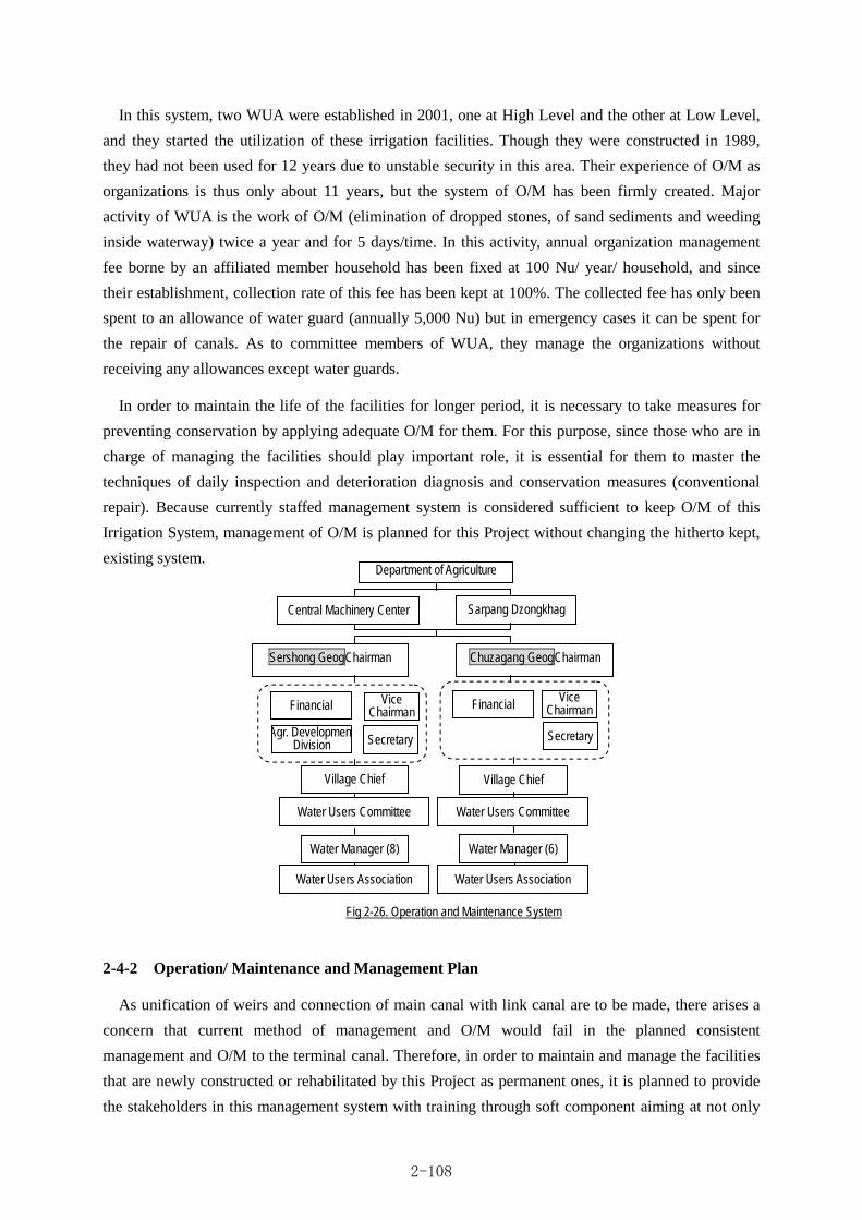
In this system, two WUA were established in 2001, one at High Level and the other at Low Level,
and they started the utilization of these irrigation facilities. Though they were constructed in 1989,
they had not been used for 12 years due to unstable security in this area. Their experience of O/M as
organizations is thus only about 11 years, but the system of O/M has been firmly created. Major
activity of WUA is the work of O/M (elimination of dropped stones, of sand sediments and weeding
inside waterway) twice a year and for 5 days/time. In this activity, annual organization management
fee borne by an affiliated member household has been fixed at 100 Nu/ year/ household, and since
their establishment, collection rate of this fee has been kept at 100%. The collected fee has only been
spent to an allowance of water guard (annually 5,000 Nu) but in emergency cases it can be spent for
the repair of canals. As to committee members of WUA, they manage the organizations without
receiving any allowances except water guards.
In order to maintain the life of the facilities for longer period, it is necessary to take measures for
preventing conservation by applying adequate O/M for them. For this purpose, since those who are in
charge of managing the facilities should play important role, it is essential for them to master the
techniques of daily inspection and deterioration diagnosis and conservation measures (conventional
repair). Because currently staffed management system is considered sufficient to keep O/M of this
Irrigation System, management of O/M is planned for this Project without changing the hitherto kept,
existing system.
2-4-2 Operation/ Maintenance and Management Plan
As unification of weirs and connection of main canal with link canal are to be made, there arises a
concern that current method of management and O/M would fail in the planned consistent
management and O/M to the terminal canal. Therefore, in order to maintain and manage the facilities
that are newly constructed or rehabilitated by this Project as permanent ones, it is planned to provide
the stakeholders in this management system with training through soft component aiming at not only
Fig 2-26. Operation and Maintenance System
Department of Agriculture
Sarpang Dzongkhag
Sershong GeogChairman Chuzagang GeogChairman
Vice Chairman
Financial
Village Chief
Water Manager (8)
Agr. DevelopmentDivision Secretary
Vice Chairman Financial
Secretary
Village Chief
Water Manager (6)
Central Machinery Center
Water Users Committee
Water Users Association
Water Users Committee
Water Users Association
2-108

introducing preventive and conservational concept as their paradigm, but also diffusing common rule
of water management and water distribution for newly constructed irrigation system among
RDC/CMU and the whole beneficiary (WUA).
The following procedural method is proposed here to manage, operate and maintain the facilities
that are newly constructed or rehabilitated by this Project.
1) to acquire basic knowledge for maintaining function and capacity of the facilities,
2) to regularly report state of routine management, and to provide minutes of reporting,
3) to master method of proper gate operation to secure relevant water distribution,
4) to perform circular inspection and preventive conservation (stock management),
5) to collect, manage and keep information on irrigation facilities,
6) to formulate an annual O/M activity plan and to maintain monitoring/ feed back and
7) to provide a manual on O/M for the irrigation facilities
Items and contents of the inspection consisting of routine inspection and regular one are proposed in
the following table.
Table 2-40: Items and contents of the routine / regular inspection
Division Contents Person in charge Frequency
Routine inspection and maintenance work
- Unusual state of the structures of the facility (deformation, subsidence, change in color, unusual sound, unfamiliar odor etc),
- Whether abnormality found in the function of facilities to maintain water conveyance or water level or not,
- Whether influence of irrigation or facility installation takes place in the ambient environment or not,
- Whether complaints has been issued from water users or the inhabitants living around the facilities or not,
- to provide and keep records of routine inspection and O/M work and - to manage O/M cost in good order.
Persons responsible for water management in WUA, supported by RDC and CMU
Once per week
Regular checking inspection and maintenance work
- Whether water distribution/ allocation is adequately performed or not, - Whether beneficiary farmers are satisfied with irrigation services or not, - Whether routine inspection and recording of maintenance activities are
performed or not, - Whether O/M cost is managed in good order or not and - to elaborate preventive conservation measures (stock management)
RDC and CMU Twice per year
2-5 Estimated project cost
2-5-1 Estimated cost for the project
The project cost to be borne by the Bhutanese side is estimated to be about 9 million JPY, with the
broken-down items as born by the Bhutanese side based on demarcated obligations as discussed above. The
estimation was done applying the estimation conditions as indicated below.
2-109

2-5-1-1 Project cost borne by the Bhutanese side
Table 2-41: Overall project cost to be borne by the Bhutanese side Cost item Cost
Repair of the access road to the construction sites 2,500,000Nu. Extension of feeding electric cable to the site management office 2,100,000Nu. Bank commission arranged by Bank Agreement 600,000Nu.
Total 5,200,000Nu. 9.05 million yen
2-5-1-2 Cost estimating assumption
(1) Time of the estimation: February 2012
(2) Foreign currency exchange rates: 1US$=78.24yen、1Nu =1.74yen
(3) period of construction /procurement: The period of detailed design and the construction period is
shown in the process of implementation.
(4) Others: The cost estimation is made in accordance with the system of Grant Aid Cooperation of
Japanese Government.
2-5-2 Management, operation and maintenance cost
The budget required for management, though the operation and maintenance of downstream of
secondary canal and personnel fee such as water gourd are collected from the beneficiary farm
households and fiscal budget of the state and Geog, above budget of the middle or large size facilities
concerning Taklai irrigation system are allocated by national budget directly.
The following table shows the costs of management, operation and maintenance of the targeted
facilities during the period of 2005 ~ 2011, out of which cost of repairing flood damages amounted to
2,500,000 Nu / year (≒ 17,001,971.27 / 7years) while ordinary O/M cost comes to 1,000,000 Nu /
year (≒ 5,659,914.04 Nu / 6 years) that are allocated from national budget, then surplus budget will
be returned to MoAF.
According to the table, the rehabilitation and maintenance cost of Taklai irrigation system come to
the 6 million Nu. in maximum which is 6 times as much as ordinary O/M cost, hence, to reduce the
cost concerning the flood measures is the issue These figures imply large amount of cost incurred to
mend flood damages , inflicting considerable economic burden to the country.
2-110

Table 2-42: Annual budge of CMU
Name of scheme Budget (Nu)
Expenditure incurred
(Nu)
FY. 2005 River Diversion works(Earth work) 1,499,812.00 ①
River Bank Protection works (Gabion and foundation works) 3,884,189.06 ②
1
sub-Total 5,384,001.06 FY. 2006-2007 Gaden bank protection (Length=820m of fore layers)
4,844,917.60 ③
For Irrigation 257,123.60 2
sub-Total 20,064,000.00 5,102,041.20 FY. 2007-2008 Low Level Intake protection work (Length=48m of fore (4) layers) 339,720.00 ④
For Irrigation 2,036,704.50 3
sub-Total 4,000,000.00 2,376,424.50 FY. 2008-2009 Low Level Intake protection work (Length=100.5m of fore (4) layers) 854,455.36 ⑤
For Irrigation 20,958.64 4
sub-Total 1,616,000.00 875,414.00 FY. 2009-2010 Renovate High Level main canal (Plastering works L=2,300m) 1,204,171.30
Steel gates (3 nos) 75,.000.00
Labors payment 20,000.00
5
sub-Total 1,500,000.00 1,299,171.30 FY. 2010-2011 Low Level main canal (Length=2,000m) 1,065,956.00 ⑥
High Level canal bank protection work (Length=138m) 399,081.65 ⑦
River bank protection (Length=283m of seven (7) layers of gabion wall) 5,179,795.60
6
sub-Total 7,680,000.00 6,644,833.25 FY. 2011-2012 Renovate High Level main canal (Length=1,500m) 980,000.00 7
sub-Total 1,000,000.00 980,000.00
Flooding injury Total (①+②+③+④+⑤+⑥+⑦) 17,001,971.27
Others Total (except for above items) 5,659,914.04 Grand total 22,661,885.31
Source: CMU
Though the O/M cost of the facilities incurred by flood damages will greatly be alleviated owing to
this Project, no significant change in annual, ordinary O/M cost is foreseen. The estimation of O/M
cost after the construction work under this Project is completed is difficult because of the difficulty in
forecasting future scale of flood occurrence, but it is desired the future annual cost burden is alleviated
to the intermediate level, approx. 1,750,000Nu/yr, between annual ordinary O/M cost of 1,000,000 Nu
/annum and flood damages mending cost of 2,500,000 Nu / annum. The responsibility of O/M is
CMU mainly same as so far.
2-111

Chapter 3 Project Evaluation

CHAPTER 3 PROJECT EVALUATION
3-1 Precondition
(1) Land acquisition and permission of construction
The construction works for the project is mainly divided the targeted area into close at Taklai River and away from Taklai River. As the all of around or close Taklai river is national land, land acquisition is not required though, the trimming and removal of vegetation at land for the candidate of stock yard around headworks site are responsibility for Bhutanese side.
The access road to the site during the construction period is planned to use the existing farm road though, understanding and sharing information concerning the construction works to the residence people in targeted are will be carried out by Bhutanese side again.
Regarding the permission of construction works, the quarry which is required for concrete works is planned to collect from Taklai River and other river near site and disposal area of excavated soil is planned at downstream near the construction site, which are explained and permitted verbally by Bhutanese side. All of permission shall be carried out by Bhutanese side.
Therefore, Land acquisition and permission of construction will be carried out without any problem.
(2) Secure of approval of IEE (Initial Environmental Examination)
The procedure of IEE is carried out follow 「Processing Environmental Clearance for Irrigation Construction Projects : A Guide for Proponents(October 2004)」in Bhutan. The approval of this project was issued by National Environment Committee on 2nd November 2012.
(3) Custom clearance procedure and tax exemption measure
As this project is the Japanese Grant Aid project, custom clearance, tax and any surcharges are exempted. These procedure of exemption shall be handled by the responsible agency of Bhutanese side
3-2 Necessary inputs by the government of Bhutan
As the electric power is not supply to the site, leading the electric power is required which is carried out by Bhutanese side prior to the construction works.
In addition, counter parts and related persons from concerning division for soft components activity shall be attended and the based office for this activity shall be provided by Bhutanese side.
3-3 Important assumption
The important assumptions in order to make the project effectiveness and sustainability shall be as follows;
・There would be no extreme climatic / metrological occurrences like severe drought and flood for a long period in Taklai river and target area.
・To perform the proper water distribution and operation through Link canal to the target area
・To sustain the O &M for the facility and maintain the intake facility
・There would be no drastic change of agricultural policy and irrigation policy in Bhutan
3-1

3-4 Project evaluation
3-4-1 Relevance
Project implementation under the grant aid scheme by the Government of Japan is considered justifiable with the following viewpoints.
(1) Targeted beneficially people
The number of beneficiaries is approximately 4,300 while household is 530. The farmer's income in this area is approximately US$ 390 (17,700 Nu ) per household. While GNI (Gross National Income) is US$ 2,070 per person in Bhutan, is means that the target area’s income is approximately one-fifth of national level. The farmers account for the majority of population in the area, therefore almost people are considered at the lower level than national level in Bhutan. Accordingly, the number of poor is higher in this area.
(2) Relationship of long term development plan
In the 10th five-year national development plan for Bhutan, the target was to reduce the ratio of poverty from 23.2 % (2007) to 15%. In addition, as there are many poor people in the rural area, rural integrated development is categorized as one of the important area for development. In addition, increase in self-sufficiency of crops is an urgent issue due to the geological condition in Bhutan therefore the aim is to increase self-sufficiency from 50% of the current rate to 59 % until 2018.
The largest irrigation system in Sarpang District in Bhutan, the Taklai irrigation system, considered as the productive crucial are in south Bhutan, is expected to contribute to the improvement of national self -sufficient of rice and agricultural production in this area with the expansion of cropped area in dry season by restraining of irrigation system facility.
The 11th five-year national development plan also plans in preparation to improve agricultural infrastructure, expansion of the irrigation area and increase farmer's income, hence the implementation of this project is expected to become a model project on agricultural development in Bhutan.
(3) Relationship of Japanese grant aid scheme and policy
A mutual concern between Bhutan and Japan, since the establishment of diplomatic relations on 28th March in 1986, is to have structured friendly relations through the exchanges between imperial and royal family and economic support such as instruction of agriculture promotion. Therefore Japan is considered as country that can provide ODA support and assistance to Bhutan, while Bhutan is considered as the important for Japan as it provides support and espousal on election or resolution at international agency to Japan.
The major emphasis for Bhutan based on Japanese policies are as follows; ① Agricultural and rural development (mechanization of agriculture, improvement of agricultural infrastructure ), ②Improvement of economic foundation (road networks, electrification of rural area, diffusion of information ), ③Social development (strengthening of the educational service, strengthening of medical and health services, development of human resources for the job creation), ④ Good governance (decentralization). In this project, ① Agricultural and rural development (mechanization of agriculture, improvement of agricultural infrastructure) are included as part of the project therefore the project conforms to policy of Japan.
3-2

In addition, according to the achievement of Millennium Development Goals (MDGs) of United Nations (UN), support to “Human security" is a crucial policy that is being promoted. The project also promotes the development and improvement of agricultural productivity to increase crop self-sufficiency The Project therefore contribute to the policy " Eradicate Extreme Poverty & Hunger" which is one of the development policy on MDGs,
Bhutan advocates Gross National Happiness (GNH) as the central priority for the national plan, which does not pursue the physical or economic improvement but spiritual improvement.. This idea is focused as though it would overcome a deadlock and cooped-up feeling of the society which has given priority to development of economical efficiency, and the examination in order to introduce the idea of GNH into a new indicator for MDGs is beginning at UN, now. Accordingly, to contribute the national policy based on GNH in Bhutan expects to contribute the achievement of MDGs.
3-4-2 Effectiveness
The expected impact of the implementation of the project is as follows;
・ Quantitative effects Table: 3-1 Indicator for the Quantitative effects
Items Base year(2012) Target year(2018) Remarks Irrigation water supply in dry season
0 m3/s max. 2.24 m3/s *1) enable to supply irrigation water by construction of head works
Irrigation area 883 ha max. 1,120 ha*2) enable to supply irrigation water by rehabilitation of damaged siphon
Paddy area in dry season
10 ha 560 ha
expand the double crop area by supplied stable water in dry season. as the condition of assumptions, the cropping pattern of irrigation area in dry season is divided to vegetable and rice by a half respectively.
Annual maintenance cost
ave.3,500,000 Nu 1,750,000 Nu alleviation of rehabilitation works for the headrace canal and protection wall by gabions
※Target year is three years later after the construction
*1) Maximum planned irrigation water is considered of probability that drought discharge of Taklai river by
examined probable rainfall might be lower than planned irrigation water, 2.24 m3/s.
*2) Actual registered house hold and beneficiaries is approximately 530 and 4,300 respectively. Those are
expected to receive the benefit directly.
・ Qualitative effects
① The farmer's income will increase with the increase in rice production and better selling price.
② With the inclusion of soft component activity, there will be improvement of O &M skills and techniques. Also, collection of data and sharing of information will contribute to keep the good condition of the irrigation facility.
③ O & M activities in Taklai irrigation system will be good model and extended to other similar area.
④ through extension of rice double crop, the operating rate of machine for agricultural works which is not used during fallow periods will increase.
⑤ The direct effect of disaster prevention for irrigation area or facility will be expected by
3-3

construction of river dike; in addition, reinforcement of existing protection wall and new construction of intake or delivery canal with good durability will bring the stabilization of irrigation facility on flood period and, accordingly, contribute to raising up rice production and farmer's income.
3-4