Embed Size (px)
Citation preview
The property of phase velocity in the cloak shell
Guan Xia Yu1∗, Xiuzhi Wang2, Jingjing Fu2, Junyuan Dong2, Min Luo1
1 School of Science , Nanjing Forestry University, Nanjing 210037, P. R. China.
2 School of Information Science and Technology, Nanjing Forestry University, Nanjing 210037, P. R. China..
OCIS codes: (160.3918) Metamaterials; (260.2110) Electromagnetic optics.
*E-mail:[email protected]
November 9, 2016
Abstract
According to classical EM field theory, the dispersion relation for anisotropic media in the
2-D cylinder cloak have been calculated in the KDB system(consisting of k⃗ vector and the DB
plane). Due to the special and variable Electromagnetic(EM) parameters, theoretical results
indicate that the phase velocities of EM waves are non-uniform in the cloak shell. The numerical
simulations show that the phase velocity is reduced, and less than that of light in vacuum in
the front and rear of cloak shell. While in the upper and lower region of cloak shell, the phase
velocities are lager than that of other regions, and exceed that of light in vacuum.
Keywords:electromagnetic fields,phase velocity ,energy flow, superluminal
PACS: 42.25.Fx, 41.20.Jb,42.70.Mp
1
2
1 Introduction
Recently, artificially structured metamaterials have attracted worldwide attention due to their un-
precedented flexibility in manipulating electromagnetic (EM) waves and producing new functionalities[1−
5]. One of the novel features is that metamaterials can produce negative permeability and per-
mittivity simultaneously. Due to the negative refraction, there are lots of unusual properties and
potential applications, such as the superlens, the energy localization, the super waveguide, and
so on[1, 6 − 7]. Besides negative refraction and cloaks, more wave manipulation strategies using
metamaterials have been drawn out, such as EM field concentrators, rotators, direction changing,
illusion optics, and so forth[8− 16].
We all know that the novel properties of metamaterials in the electromagnetic fields are due to
the flexible, variable and anisotropic electromagnetic parameters, and the special materials can be
designed and fabricated by man-made periodic and aperiodic structure units. In these peculiar
materials, there exist many physical laws which can not be found in nature materials. One of the
unusual peculiarities is propagation properties of EM waves in the metamaterials, such as phase
velocity, energy flow velocity, which has been few reported in the literatures. When a plane waves
incident on a cloak(Fig.1a), these fields can be compressed in the shell as required or made to avoid
objects to be found, and flow around them like a fluid, returning undisturbed to their original
trajectories. In the cloak shell, the EM fields in the inner regions are required to follow a more
curved and longer trajectory than that in the outer regions, and all the EM waves in the cloak shell
are required the same phase as that in the free space.
In this paper, we have focused on the propagation characteristics of the electromagnetic waves in
the general anisotropic medium, and investigated the distribution of phase velocities in the cloak
shell. Firstly, the dispersion relation for general anisotropic medium has been deduced in the KD-
B system[17] based on classical EM fields theory. Secondly, the phase velocity of in the general
3
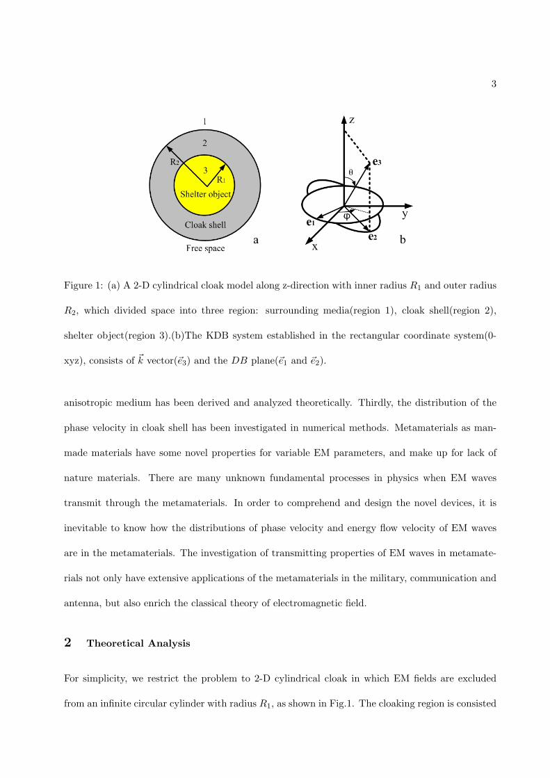
Figure 1: (a) A 2-D cylindrical cloak model along z-direction with inner radius R1 and outer radius
R2, which divided space into three region: surrounding media(region 1), cloak shell(region 2),
shelter object(region 3).(b)The KDB system established in the rectangular coordinate system(0-
xyz), consists of k⃗ vector(e⃗3) and the DB plane(e⃗1 and e⃗2).
anisotropic medium has been derived and analyzed theoretically. Thirdly, the distribution of the
phase velocity in cloak shell has been investigated in numerical methods. Metamaterials as man-
made materials have some novel properties for variable EM parameters, and make up for lack of
nature materials. There are many unknown fundamental processes in physics when EM waves
transmit through the metamaterials. In order to comprehend and design the novel devices, it is
inevitable to know how the distributions of phase velocity and energy flow velocity of EM waves
are in the metamaterials. The investigation of transmitting properties of EM waves in metamate-
rials not only have extensive applications of the metamaterials in the military, communication and
antenna, but also enrich the classical theory of electromagnetic field.
2 Theoretical Analysis
For simplicity, we restrict the problem to 2-D cylindrical cloak in which EM fields are excluded
from an infinite circular cylinder with radius R1, as shown in Fig.1. The cloaking region is consisted
4
of a concentric cylindrical shell with inside radius R1 and outside radius R2, which is filled with
the following radius-dependent, anisotropic relative permittivity and permeability (in rectangular
coordinates):
ϵ̄r = µ̄r =
∣∣∣∣∣∣∣∣∣∣∣∣∣
exx exy 0
eyx eyy 0
0 0 ezz
∣∣∣∣∣∣∣∣∣∣∣∣∣(1)
where exx = rr−R1
− (2R1r−R21)x
2
r3(r−R1), exy = eyx = − (2R1r−R2
1)xyr3(r−R1)
, eyy = rr−R1
− (2R1r−R21)y
2
r3(r−R1)and
e33 = ( R2R2−R1
)2 r−R1r . The cloak shell separate space into three region:free space(region 1),cloak
shell(region 2), sheltered region(region 3).
In order to investigate the EM properties in the the anisotropic media, a new coordinated system
called KDB system has been established in the rectangular coordinate system, which is consisted
of k⃗ vector and the DB plane(Fig.1b). The KDB system has unit vectors e⃗1, e⃗2, e⃗3, and θ is angles
between e⃗3 and z⃗, ϕ is angles between e⃗2-e⃗3 plane and x⃗. The components of field vectors and EM
parameters in the rectangular coordinate system can be transform into a new forms in the KDB
system using transition matrix T :
T =
∣∣∣∣∣∣∣∣∣∣∣∣∣
sinϕ −cosϕ 0
cosθcosϕ cosθsinϕ −sinθ
sinθcosϕ sinθsinϕ cosθ
∣∣∣∣∣∣∣∣∣∣∣∣∣(2)
Without loss of generality, a transverse-electric (TE) plane waves along z−polarization are incident
from the left side of cloak, and the electric field can be written as:E1z = E0eikyy, where the time-
dependent factor eiωt is assumed and omitted in notations. In this case, ϕ = 12π, the transition
5
matrix T can be simplified as follows:
T =
∣∣∣∣∣∣∣∣∣∣∣∣∣
1 0 0
0 cosθ −sinθ
0 −sinθ cosθ
∣∣∣∣∣∣∣∣∣∣∣∣∣(3)
The relation between a vector A⃗ in the rectangular coordinate system and the same vector A⃗k
in the KDB system is governed by A⃗k = TA⃗, where subscript k represents a vector in the KDB
system. Therefore, the relations of the field vectors in two different systems can be expressed as:
E⃗k =¯̄κkϵ0
D⃗k (4)
H⃗k =¯̄νkµ0
D⃗k (5)
where ϵ0 and µ0 are the permittivity and permeability in a vacuum, respectively. ¯̄κk and ¯̄νk are
quantities related to relative permittivity and permeability of anisotropic medium in the KDB
system, which are defined as:¯̄κk = T ¯̄κT−1,¯̄νk = T ¯̄νT−1, where T−1 is the inverse of T . In our
system, ¯̄κk and ¯̄νk can be written as:
¯̄κr = ¯̄νr =
∣∣∣∣∣∣∣∣∣∣∣∣∣
ekxx ekxycosθ ekxysinθ
ekxycosθ ekyycos2θ + ekzzsin
2θ 0
ekxysinθ (ekyy − ekzz)sinθcosθ ekzzcos2θ + ekyysin
2θ
∣∣∣∣∣∣∣∣∣∣∣∣∣(6)
in which ekxx = exx/m, ekxy = ekyx = −exy/m, ekyy = eyy/m, ekzz = 1/ezz, and m = exxeyy −
exyeyx.
Within the frame of KDB system, the Maxwell equations for the TE plane waves take the same
form as those in the rectangular coordinate system. Due to wave vector k⃗ in the e⃗3 direction, it is
easy to have B⃗ke3 = D⃗ke3 = 0 according to k⃗ · B⃗k = 0 and k⃗ · D⃗k = 0. Based on k⃗× E⃗k = ωB⃗k and
k⃗ × H⃗k = −ωD⃗k, the EM fields components of e⃗1 and e⃗2 direction can be rearranged and written

6
in the matrix form: κ11 κ12
κ21 κ22
Dk1
Dk2
= −ϵ0ω
0 −k
k 0
Bk1
Bk2
(7)
ν11 ν12
ν21 ν22
Bk1
Bk2
= −µ0
ω
0 k
−k 0
Dk1
Dk2
(8)
where ω is angular frequency. Eliminating Bk or Dk in the equation(7) and (8), and defining
c0 = 1/√ϵ0µ0( the speed of light in a vacuum ), the dispersion relation for anisotropic media can
be obtained:
ω4 − c20(a1k2z + b1k
2s)ω
2 + c40(c1k4z + d1k
4s + e1k
2zk
2s) = 0 (9)
where kz = kcosθ and ks = ksinθ are wave numbers in z−direction and transverse direction,
respectively, and a1 = 2(e2kxx − e2kxy)− 2e2kxy, b1 = ekxxekzz, c1 = 2(e2kxx − e2kxy), d1 = (ekxxekzz)2,
and e1 = 2(e2kxx − e2kxy)(ekxxekzz). For given angular frequency ω, there are four solutions for k
in the equation (9), which are corresponding to the type 1 wave and the type 2 wave of forward
propagation and backward propagation in the general anisotropic media. If the exy = eyx = 0 in
the formula 1, the general anisotropic media is reduces to biaxial anisotropy medium. The equation
(9) can be simplified as fowllows:
[ω2 − c201
exx(1
eyyk2z +
1
ezzk2s)][ω
2 − c20(1
exxk2z +
1
ezzk2s)] = 0 (10)
This equation can be decomposed into the two familiar dispersion relations of TE mode and TM
mode waves.
Applying phase velocity u = ω/k and formula (9), the phase speed in the anisotropic media can be
obtained:
v4 − (c0k)2(a1k
2z + b1k
2s)v
2 + (c0k)4(c1k
4z + d1k
4s + e1k
2zk
2s) = 0 (11)
7
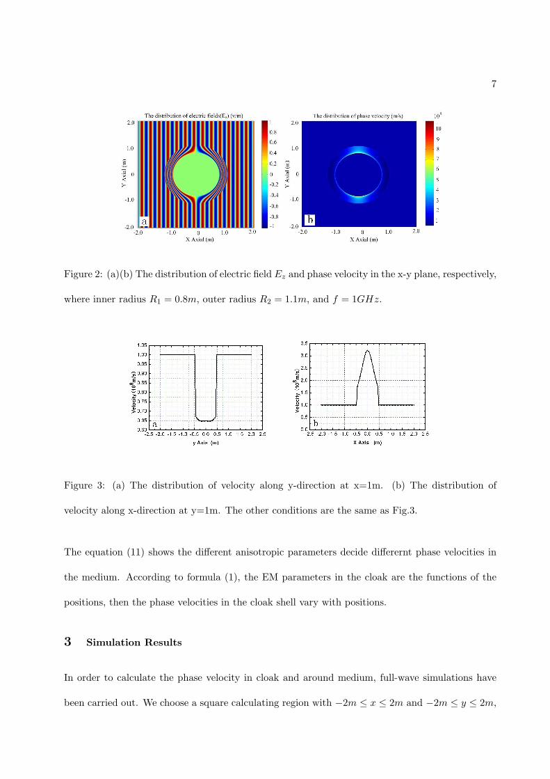
Figure 2: (a)(b) The distribution of electric field Ez and phase velocity in the x-y plane, respectively,
where inner radius R1 = 0.8m, outer radius R2 = 1.1m, and f = 1GHz.
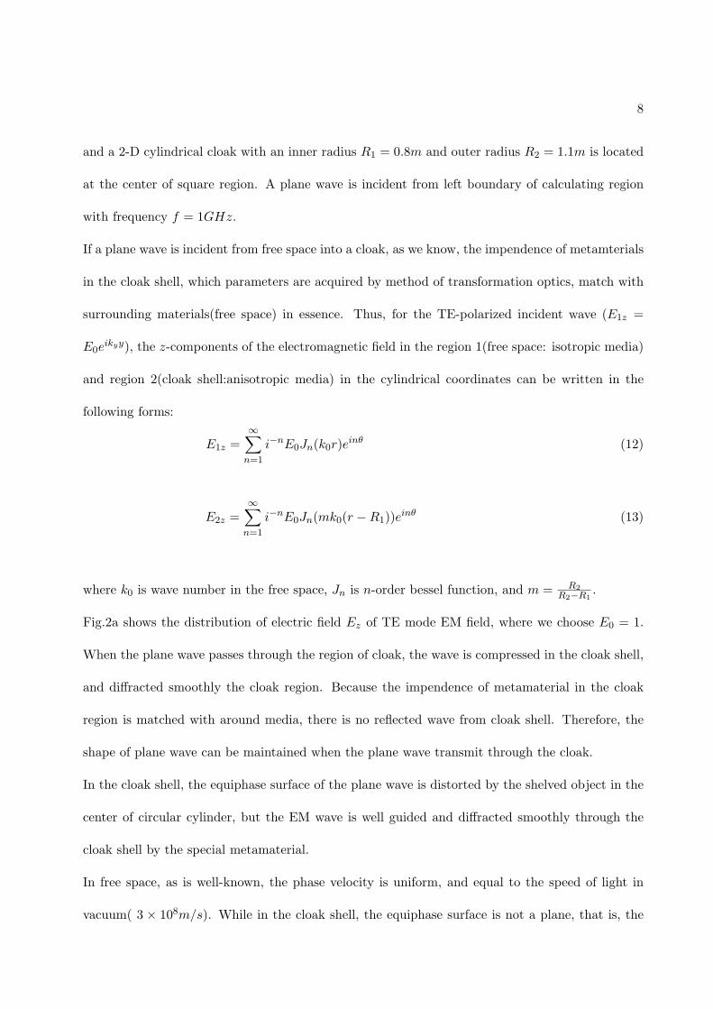
Figure 3: (a) The distribution of velocity along y-direction at x=1m. (b) The distribution of
velocity along x-direction at y=1m. The other conditions are the same as Fig.3.
The equation (11) shows the different anisotropic parameters decide differernt phase velocities in
the medium. According to formula (1), the EM parameters in the cloak are the functions of the
positions, then the phase velocities in the cloak shell vary with positions.
3 Simulation Results
In order to calculate the phase velocity in cloak and around medium, full-wave simulations have
been carried out. We choose a square calculating region with −2m ≤ x ≤ 2m and −2m ≤ y ≤ 2m,
8
and a 2-D cylindrical cloak with an inner radius R1 = 0.8m and outer radius R2 = 1.1m is located
at the center of square region. A plane wave is incident from left boundary of calculating region
with frequency f = 1GHz.
If a plane wave is incident from free space into a cloak, as we know, the impendence of metamterials
in the cloak shell, which parameters are acquired by method of transformation optics, match with
surrounding materials(free space) in essence. Thus, for the TE-polarized incident wave (E1z =
E0eikyy), the z-components of the electromagnetic field in the region 1(free space: isotropic media)
and region 2(cloak shell:anisotropic media) in the cylindrical coordinates can be written in the
following forms:
E1z =∞∑n=1
i−nE0Jn(k0r)einθ (12)
E2z =∞∑n=1
i−nE0Jn(mk0(r −R1))einθ (13)
where k0 is wave number in the free space, Jn is n-order bessel function, and m = R2R2−R1
.
Fig.2a shows the distribution of electric field Ez of TE mode EM field, where we choose E0 = 1.
When the plane wave passes through the region of cloak, the wave is compressed in the cloak shell,
and diffracted smoothly the cloak region. Because the impendence of metamaterial in the cloak
region is matched with around media, there is no reflected wave from cloak shell. Therefore, the
shape of plane wave can be maintained when the plane wave transmit through the cloak.
In the cloak shell, the equiphase surface of the plane wave is distorted by the shelved object in the
center of circular cylinder, but the EM wave is well guided and diffracted smoothly through the
cloak shell by the special metamaterial.
In free space, as is well-known, the phase velocity is uniform, and equal to the speed of light in
vacuum( 3 × 10⁸m/s). While in the cloak shell, the equiphase surface is not a plane, that is, the
9
phase velocities in the same equiphase surface are not equivalence and non-uniform distribution.
According to formula (11), the distribution of phase velocities in the x − y plane are shown in
the Fig.(2b). In the front and the rear of cloak shell, the EM waves are compressed in the cloak
shell, and the equiphase surfaces lag behind those in the free space. At the same time, in the two
regions, the phase velocity is reduced, and less than that of the velocity of light in vacuum. Fig.3a
shows that the distribution of phase velocity along y−direction at x = 1m. Between y = −0.5m
and y = 0.5m, the phase velocity is only 0.6 − 0.7 times speed of light in vacuum. We also can
see the lower the phase velocity is, the closer to outer boundary the positions are in the front
and the rear of cloak shell( Fig.(2b)). However, in the middle region(the upper and the lower of
circle cylinder along direction of propagation) of cloak shell, the phase velocities are lager than
that of other region, and exceed that of light in vacuum(Fig.2b). In the region, the phase velocity
is sped up to make up the velocity loss in the front and rear of cloak shell. Fig.3b shows that the
distribution of phase velocity along x−direction at y = 1m. Between x = −0.5m and x = 0.5m,
the phase velocity reaches 1.5 − 3.5 times velocity of light in vacuum. Also, the phase velocity is
not non-uniform distributions, and the phase velocity increase sharply near the inner boundary of
cloak shell( Fig.(2b)).
Although the superluminal phenomena is rare in the normal nature medium, the special phenomena
can be appeared in the anomalous dispersion medium. Based on Einstein’s special theory of
relativity, the speed of a moving object can not exceed that of light in vacuum. Because the speed
of moving object in the Einstein’s special theory of relativity is related to the speed of energy
flow, the superluminal phenomena of phase velocity in the the anomalous dispersion medium is not
inconsistent with it. In the isotropic nondispersive media, the phase velocity of EM waves can be
simplified as:v = 1√ϵµ , in which ϵ and µ are the EM parameters of medium. Because EM parameters
in the free space is less than that of other media, the velocity of the phase in the general media is
less than the velocity of light in vacuum. Metmaterial as a special man-made materials, has variable
10
EM parameters(Formula (1)), which can be designed and fabricated by structure units arranged
periodically or aperiodically. The special variable EM parameters can be larger or less than the
values of nature materials, even equal to zero or less than zero. According to classical theories on
electromagnetic field, the less EM parameters are, the lager of the phase velocity and energy flow
of EM waves are. Thus, when the EM parameters in the metamaterials are less than that of nature
materials, the faster-than-light EM waves in the metamaterials are common phenomena.
4 Conclusion
In this paper, the dispersion relation and the phase velocity for anisotropic media in the 2-D
cylinder cloak have been calculated in the KDB system according to classical EM field theory.
The theoretical analysis and simulations show that there is superluminal phenomena in the cloak
shell consisting of metamaterials. In the upper and the lower region of cloak shell, the phase
velocities are lager than that of other region, and exceed that of light in vacuum. While in the
front and the rear of cloak shell, the phase velocity is reduced and less than that of light in vacuum.
The investigation of transmitting properties of EM waves in metamaterials not only have extensive
applications in the military, communication and antenna, but also enrich the classical theory of
electromagnetic field.
References
[1] J. B. Pendry. Negative Refraction Makes a Perfect Lens. Phys. Rev. Lett. 85,3966,2000
[2] J. B. Pendry, D. Schurig , D. R.Smith. Controlling Electromagnetic Fields. Science,
312,1780,2006
[3] D. Schurig, J. J. Mock, B. J. Justice, S. A. Cummer, J. B. Pendry, A. F. Starr, and D.R. Smith.
Metamaterial electromagnetic cloak at microwave frequencies. Science, 314,314,977,2006
11
[4] R. Marco, A. C. Steven, D. Schurig, J. B. Pendry, and D. R. Smith. Optical Design of Re-
flectionless Complex Media by Finite Embedded Coordinate Transformations. Phy. Rev.Lett.,
100,063903,2008
[5] Y. Lai, J. Ng, H. Y. Chen, D. Z. Han, J. J. Xiao, Z. Q. Zhang, and C. T. Chan. Illusion
Optics: The Optical Transformation of an Object into Another Object, Phys. Rev. Lett., 102,
253902,2009
[6] J. P. Camps, C. Navau, and A. Sanchez. Experimental realization of magnetic energy concen-
tration and transmission at a distance by metamaterials. App. Phy. Let., 105, 234101,2014
[7] Q. Cheng and T. J. Cui. High-power generation and transmission through a left-handed ma-
terial. Phys. Rev. B, 72, 113112,2005
[8] D. R. Smith, J. J. Mock, A. F. Starr, D. Shurig. Gradient index metamaterials. Phys. Rev. E,
71,036609,2005
[9] M. Silveirinha, N. Engheta. Tunneling of Electromagnetic Energy through Subwavelength
Channels and Bends using -Near- Zero Materials. Phys. Rev. Lett.,97,157403,2006
[10] M. Silveirinha, N. Engheta. Tunneling of Electromagnetic Energy through Subwavelength
Channels and Bends using -Near- Zero Materials. Phys. Rev. Lett.,97,157403,2006
[11] H.Y. Chen, C.T.Chan. Transformation Media that Rotate Eleatromagnetic Fields,App. Phy.
Let., 90, 241105, 2007
[12] H. F. Ma, J. H. Shi, B. G. Cai and T. J. Cui, Total Transmission and Super Reflection Realized
by Anisotropic Zero-index Materials. New Journal Physics, 14,123010,2012
[13] W. X. Jiang,B. B. Xu,Q. Cheng,T. J. Cui, and G. X. Yu,Design and rigorous analysis of
transformation-optics scaling devices,J. Opt. Soc. Am. A,30,1698,2013
12
[14] G.Y. Nie, Q.C. Shi, Z. Zhu, and J.H. Shi,Selective coherent perfect absorption in metamate-
rials,App. Phy. Let., 105, 201909, 2014
[15] Y. Kasahara, Metamaterial waveguides with highly controllable negative-permittivity band-
s,App. Phy. Let., 105, 241111, 2014
[16] B. B. Xu, W. X. Jiang, G. X. Yu,T. J. Cui, Annular focusing lens based on transformation
optics,J. Opt. Soc. Am. A,31,1135,2014
[17] J. A. Kong, Electromagnetic wave theory. Wiley-interscience publication,1990