Embed Size (px)
Citation preview
december 2008 MODERN STEEL CONSTRUCTION
steel bridge news NatioNal Steel bridge alliaNce
As Ithaca, N.Y. has grown over the years, one of its most significant spans needed to keep up.
I“IThaCa IS GORGES.” Ezra Cornell and his associate Andrew Dickson White capitalized on this now-trademarked phrase to bring students to their new university in 1868. Recognizing the significance of the setting and reputation of Cornell Uni-versity, the City of Ithaca and the New York State Department of Transportation (NYSDOT) implemented a first-of-its-kind design to retain a bit of history in combination with a bit of invention for the rehabilitation of Cornell’s primary link over the Fall Creek Gorge.
The 181-ft-long crossing serves more than 34,000 students, faculty, and staff, but severe congestion was causing pedestrians to walk in the travel lanes and cars and buses to be held up at the approach intersection. To solve the problem, induction-bent hollow structural section (HSS) arches were tied to two existing arches to widen the Thurston Avenue “gateway” between the residential and academic campuses of the university.
Saving the archesThe original bridge was constructed more than a century
ago. When the Ithaca Street Railway Co. decided to extend its trolley service from downtown Ithaca to the Cornell University
campus in 1897, a steel arch bridge was built over the Fall Creek Gorge.
After the trolley service stopped, the city took ownership of the bridge, converting it for vehicular and pedestrian use. They replaced the bridge in 1960 with a two-rib steel box-deck arch structure. By 2001, pedestrian and bicycle counts revealed that the university and the surrounding area had significantly out-grown the bridge, which was operating at maximum capacity and at an extremely low level of service. Improved function, safety, and movement through this critical corridor were neces-sary, and the bridge could not accommodate these needs with-out major rehabilitation or replacement.
During preliminary design of the new bridge, the existing 1960 span was found to be included in NYSDOT’s Inventory of Historic Bridges due to the rare type of the existing arches and specific “character-defining” features, including curved floor beam ends and vertical picket bridge railings. This designation extensively increased the level of alternative analysis required to reach a solution that would accommodate the needs of multiple interests.
The solution was to widen the bridge 12 ft by adding new
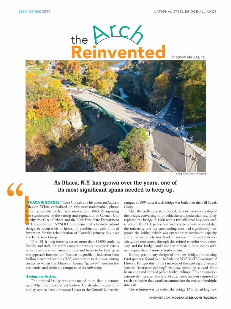
craig Shaw, Stratus imaging
archReinventedthe
by SuSaN matzat, P.e.
“
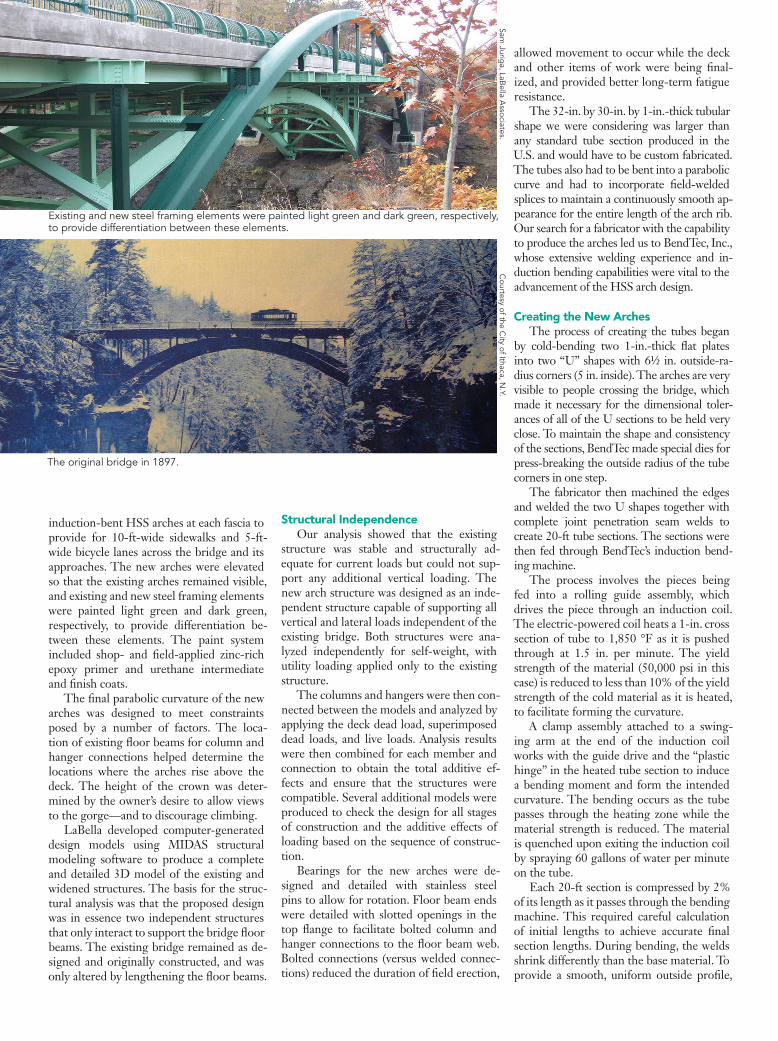
induction-bent HSS arches at each fascia to provide for 10-ft-wide sidewalks and 5-ft-wide bicycle lanes across the bridge and its approaches. The new arches were elevated so that the existing arches remained visible, and existing and new steel framing elements were painted light green and dark green, respectively, to provide differentiation be-tween these elements. The paint system included shop- and field-applied zinc-rich epoxy primer and urethane intermediate and finish coats.
The final parabolic curvature of the new arches was designed to meet constraints posed by a number of factors. The loca-tion of existing floor beams for column and hanger connections helped determine the locations where the arches rise above the deck. The height of the crown was deter-mined by the owner’s desire to allow views to the gorge—and to discourage climbing.
LaBella developed computer-generated design models using MIDAS structural modeling software to produce a complete and detailed 3D model of the existing and widened structures. The basis for the struc-tural analysis was that the proposed design was in essence two independent structures that only interact to support the bridge floor beams. The existing bridge remained as de-signed and originally constructed, and was only altered by lengthening the floor beams.
existing and new steel framing elements were painted light green and dark green, respectively, to provide differentiation between these elements.
the original bridge in 1897.
courtesy of the c
ity of ithaca, N.y.
Sam Jurig
a, labella a
ssociates.
Structural Independence Our analysis showed that the existing
structure was stable and structurally ad-equate for current loads but could not sup-port any additional vertical loading. The new arch structure was designed as an inde-pendent structure capable of supporting all vertical and lateral loads independent of the existing bridge. Both structures were ana-lyzed independently for self-weight, with utility loading applied only to the existing structure.
The columns and hangers were then con-nected between the models and analyzed by applying the deck dead load, superimposed dead loads, and live loads. Analysis results were then combined for each member and connection to obtain the total additive ef-fects and ensure that the structures were compatible. Several additional models were produced to check the design for all stages of construction and the additive effects of loading based on the sequence of construc-tion.
Bearings for the new arches were de-signed and detailed with stainless steel pins to allow for rotation. Floor beam ends were detailed with slotted openings in the top flange to facilitate bolted column and hanger connections to the floor beam web. Bolted connections (versus welded connec-tions) reduced the duration of field erection,
allowed movement to occur while the deck and other items of work were being final-ized, and provided better long-term fatigue resistance.
The 32-in. by 30-in. by 1-in.-thick tubular shape we were considering was larger than any standard tube section produced in the U.S. and would have to be custom fabricated. The tubes also had to be bent into a parabolic curve and had to incorporate field-welded splices to maintain a continuously smooth ap-pearance for the entire length of the arch rib. Our search for a fabricator with the capability to produce the arches led us to BendTec, Inc., whose extensive welding experience and in-duction bending capabilities were vital to the advancement of the HSS arch design.
Creating the New archesThe process of creating the tubes began
by cold-bending two 1-in.-thick flat plates into two “U” shapes with 6½ in. outside-ra-dius corners (5 in. inside). The arches are very visible to people crossing the bridge, which made it necessary for the dimensional toler-ances of all of the U sections to be held very close. To maintain the shape and consistency of the sections, BendTec made special dies for press-breaking the outside radius of the tube corners in one step.
The fabricator then machined the edges and welded the two U shapes together with complete joint penetration seam welds to create 20-ft tube sections. The sections were then fed through BendTec’s induction bend-ing machine.
The process involves the pieces being fed into a rolling guide assembly, which drives the piece through an induction coil. The electric-powered coil heats a 1-in. cross section of tube to 1,850 °F as it is pushed through at 1.5 in. per minute. The yield strength of the material (50,000 psi in this case) is reduced to less than 10% of the yield strength of the cold material as it is heated, to facilitate forming the curvature.
A clamp assembly attached to a swing-ing arm at the end of the induction coil works with the guide drive and the “plastic hinge” in the heated tube section to induce a bending moment and form the intended curvature. The bending occurs as the tube passes through the heating zone while the material strength is reduced. The material is quenched upon exiting the induction coil by spraying 60 gallons of water per minute on the tube.
Each 20-ft section is compressed by 2% of its length as it passes through the bending machine. This required careful calculation of initial lengths to achieve accurate final section lengths. During bending, the welds shrink differently than the base material. To provide a smooth, uniform outside profile,
december 2008 MODERN STEEL CONSTRUCTION
lab
ella
ass
ocia
tes
BendTec machined the tubes and the out-side surface of the seam welds.
They also developed detailed shop draw-ings for and fabricated all of the new steel members, including two 181-ft by 38-ft rise tubular arches, four arch bearings, 20 15-ft curved-flange floor beam extensions, eight columns, 12 hangers, 44 stringer beams, and all of the new bracing struts.
To ensure that all pieces would fit prop-erly during erection and that all internal stiffeners and connections plates were prop-erly located, BendTec welded the 20-ft bent sections together to create two end sections and one crown section per arch, and as-sembled each full-length arch, including the columns, hangers, and bracing, in its shop.
The internal stiffeners and connection plates for each of the support points were not welded in until after the sections were disassembled and the welds between the 20-ft sections were cut back out. After the internal welds were tested, the 20-ft sections were welded back together to create the fi-nal end and crown sections for each of the two new arches.
HSS arch ribs curved by the induction bending process had not been designed or constructed by NYSDOT before. To ensure that details, initial and final material prop-erties, and fatigue resistance were achieved as expected, they imposed stringent certifi-cation and testing requirements. Shop and field testing and inspection of the fabrication and bending process, welding procedures, and erection procedures were required.
Plate bends were magnetic particle tested and all welds received radiographic and ul-trasonic testing in accordance with the New York State Steel Construction Manual. The induction bending process followed TPA-IBS-98 Recommended Standards for Induction Bending of Pipe and Tube by the Tube and Pipe Association, International. Surface hardness, tensile strength, and Charpy V-notch tests were required for each arch extrados, intra-dos, each side, and all rib corners.
Longitudinal and circumferential butt welds between individual tube sections met AWS D1.5 requirements after induction bending and post-bend heat treatment. A test bend was done to ensure the material properties met the required specifications. The impact property achieved for the tube sections was 25 ft/lb at 40 °F.
Bringing New and Old TogetherAs fabrication was progressing, demoli-
tion of the existing sidewalks and construc-tion of the new arch footings were taking place. The bottom shoe of each bearing was installed on the new footings, and the curved ends of the existing floor beams were cut. New bracing struts were fed through
the existing structure and held in place with cables attached to the existing steel until they could be bolted to the new arches.
Once delivered, each arch was erected by setting the end pieces first, followed by the center piece with one crane on the bridge and one additional crane at each approach. The splice ends were fabricated with a back-ing tube that allowed the crown section to be dropped in without springing the two end sections.
The cranes held the arch sections in place for approximately 16 hours until tem-porary stand-offs and new bracing struts were connected to each arch and complete joint penetration butt welds at the splices were finished and tested. The splice welds were completed using the shielded metal arc welding process and received radiographic and ultrasonic testing.
When the existing floor beams were cut, a portion of the bottom flange was main-tained, straightened, and connected to new curved extension sections with bolted splic-es. The columns and hangers were then at-tached to the floor beams and arches. Initial connections used erection bolts only. Final connections were not completed until the deck had been removed and replaced.
Each arch was filled with pressurized nitrogen gas. The gas was pumped into the arch, replacing all of the air inside, and then sealed with a slightly positive pressure to provide an internal corrosion protection system. Permanent pressure gauges ensure that pressure loss does not occur.
On (but not Over) the EdgeAn additional distinctive feature of the
rehabilitation is the custom steel bridge rail-ing. The railing system integrates a crash-tested 16-in.-high concrete “brush curb” with a continuous round steel rail at 28 in. high for vehicular protection, with a pedes-trian railing component designed to meet
AISC’s architecturally exposed structural steel requirements.
The pedestrian component was designed as a vertical extension of inwardly curved bridge rail posts and 1-in.-diameter vertical pickets. The railing, which was galvanized then powder-coated, includes an aluminum top rail at 55 in. high that incorporates em-bedded LED strips to light the sidewalks for pedestrian safety. In addition, staged con-struction was used so the four-way intersec-tion at the southern bridge approach could be reconstructed.
The challenges of the $8.1 million proj-ect spurred the design team and the City of Ithaca to pay attention to—and truly appre-ciate—the uniqueness of the arch structure. And it’s paid off in more ways than one; in addition to state and local awards, the proj-ect just received the Award of Excellence for the Federal Highway Administration’s 2008 Excellence in Highway Design Biennial Awards in the category “Structures Costing Less than $10 million.”
Opportunities to create distinctive de-signs and apply new fabrication methods, as experienced with the Thurston Avenue Bridge project, are invaluable to expanding our knowledge base and moving the indus-try forward.
Susan Matzat is a senior structural engineer and project manager with LaBella Associates, P.C.
Ownercity of ithaca, N.y.
Bridge Designlabella associates, P.c., rochester, N.y.
Steel Fabricator and Detailerbendtec, inc., duluth, minn. (aiSc/NSba member)
General Contractoreconomy Paving, inc., cortland, N.y.
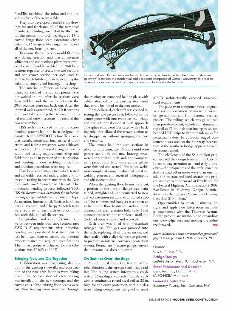
induction-bent HSS arches were tied to two existing arches to widen the thurston avenue “gateway” between the residential and academic campuses of cornell university, in order to relieve congestion caused by major increases in foot and vehicle traffic.