Embed Size (px)
Citation preview
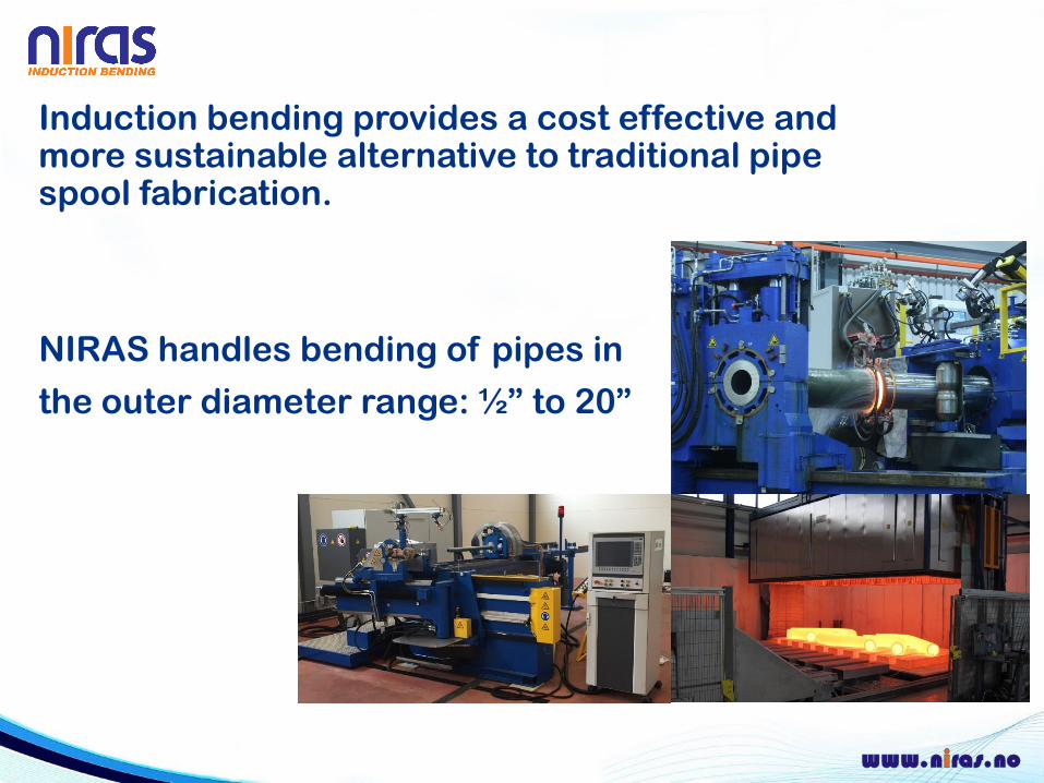
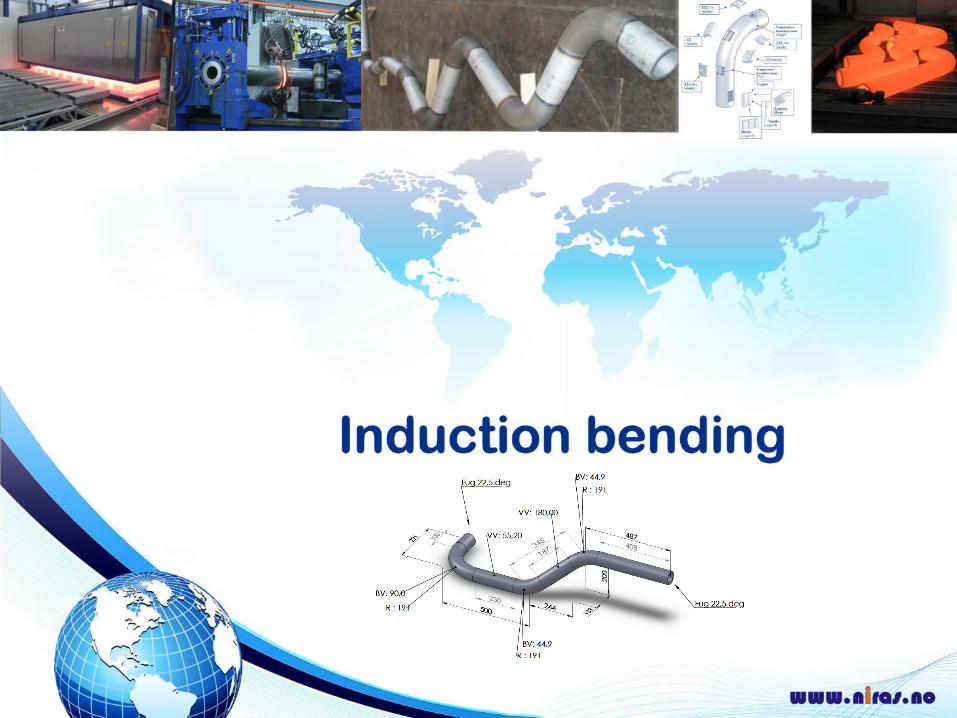
Induction bending provides a cost effective and more sustainable alternative to traditional pipe spool fabrication.
NIRAS handles bending of pipes in
the outer diameter range: ½” to 20”

Laboratory:
• Microstructural analysis
• Hardness testing
• Corrosion testing
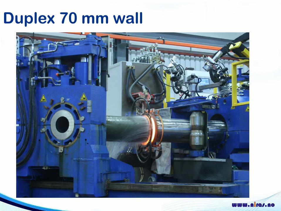
Duplex 70 mm wall
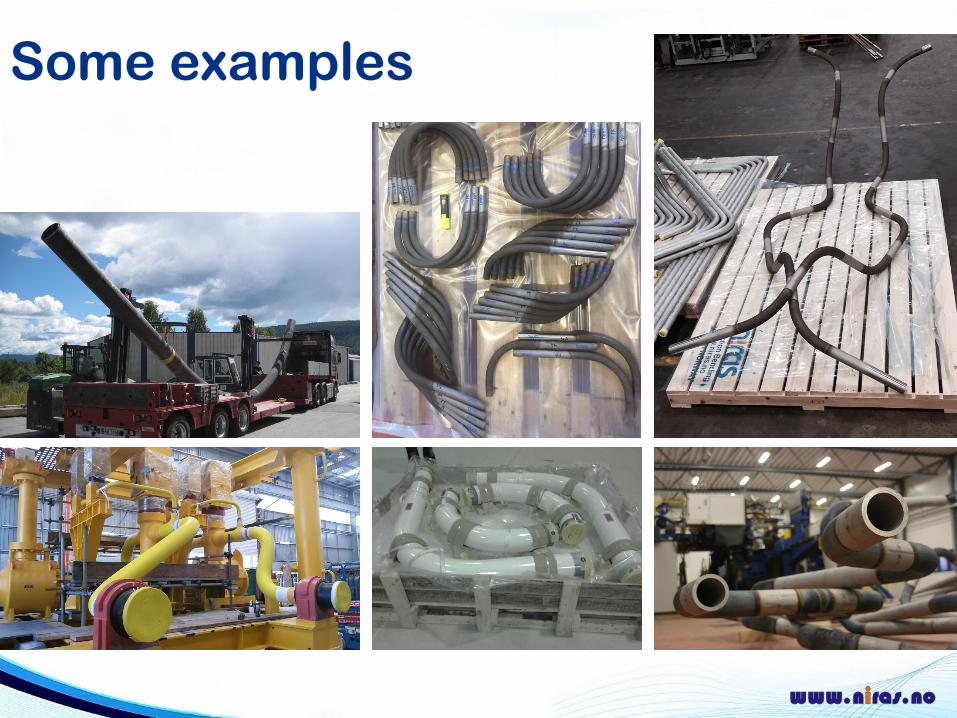
Some examples
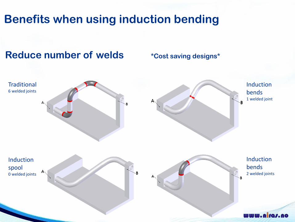
Reduce number of welds *Cost saving designs*
Traditional6 welded joints
Induction spool0 welded joints
Induction bends1 welded joint
Induction bends2 welded joints
Benefits when using induction bending
Benefits when using induction bending
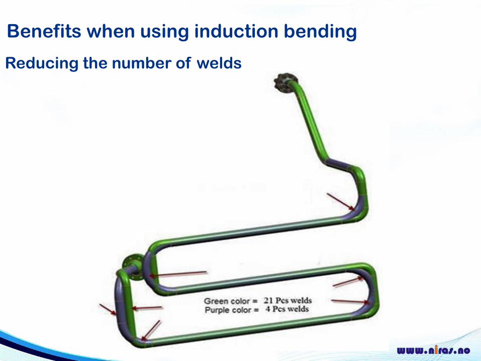
Reducing the number of welds
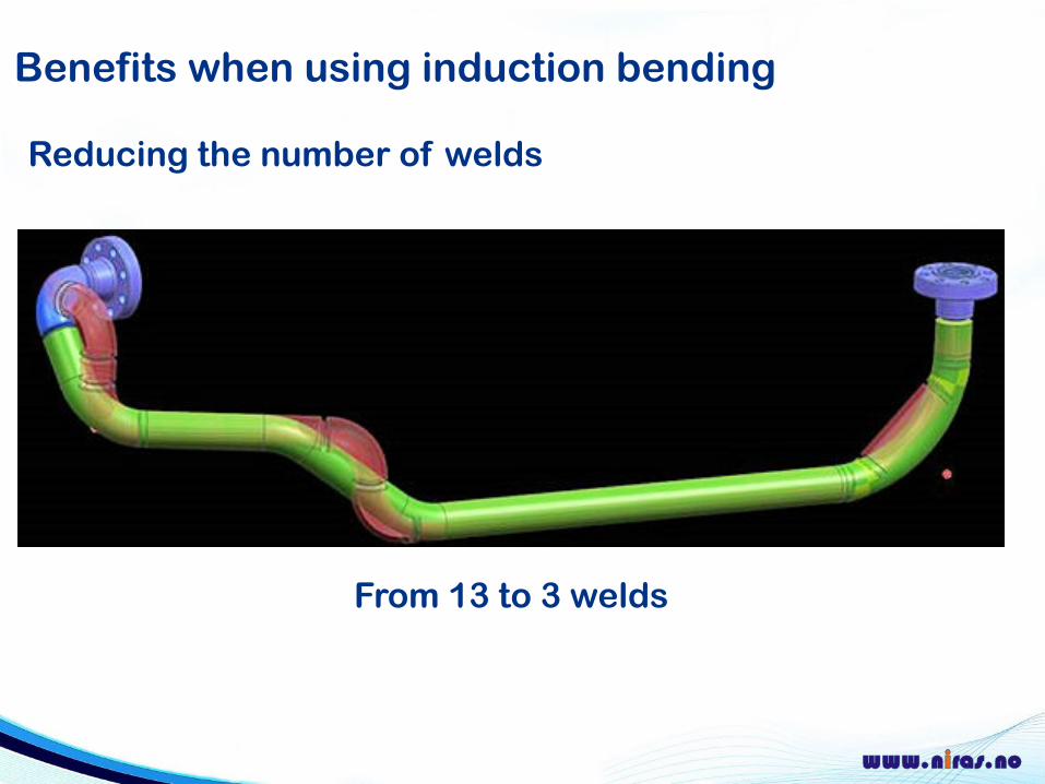
From 13 to 3 welds
Reducing the number of welds
Benefits when using induction bending
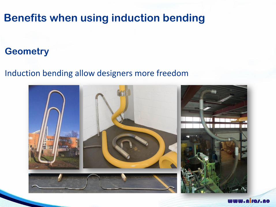
Geometry
Induction bending allow designers more freedom
Benefits when using induction bending
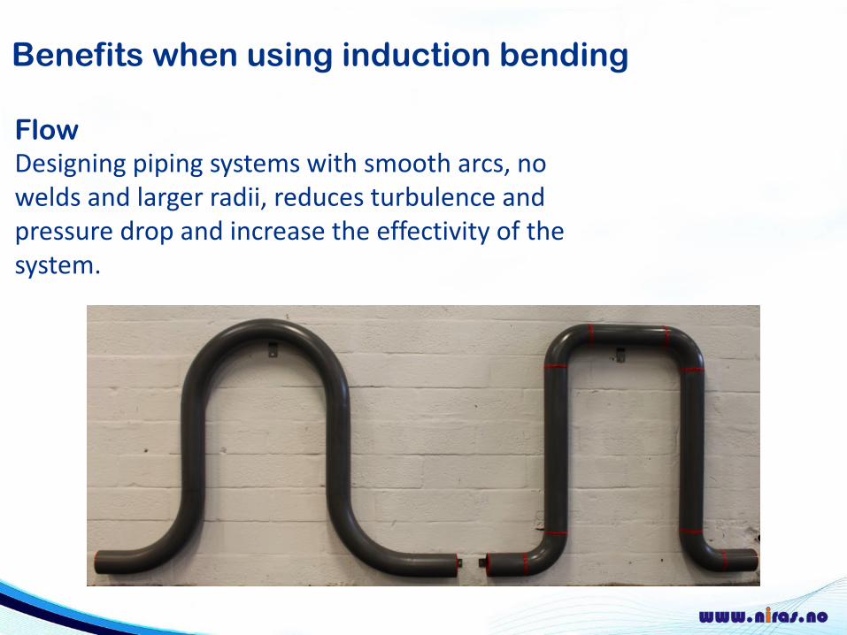
FlowDesigning piping systems with smooth arcs, no welds and larger radii, reduces turbulence and pressure drop and increase the effectivity of the system.
Benefits when using induction bending
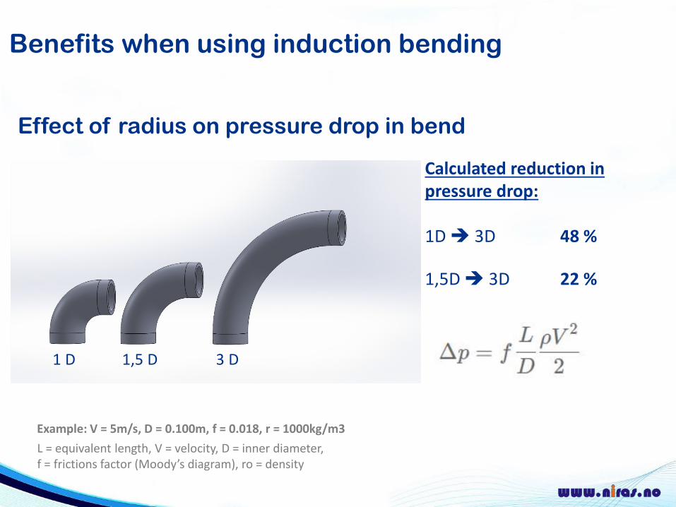
Effect of radius on pressure drop in bend
Calculated reduction in pressure drop:
1D 3D 48 %
1,5D 3D 22 %
1 D 1,5 D 3 D
L = equivalent length, V = velocity, D = inner diameter, f = frictions factor (Moody’s diagram), ro = density
Example: V = 5m/s, D = 0.100m, f = 0.018, r = 1000kg/m3
Benefits when using induction bending
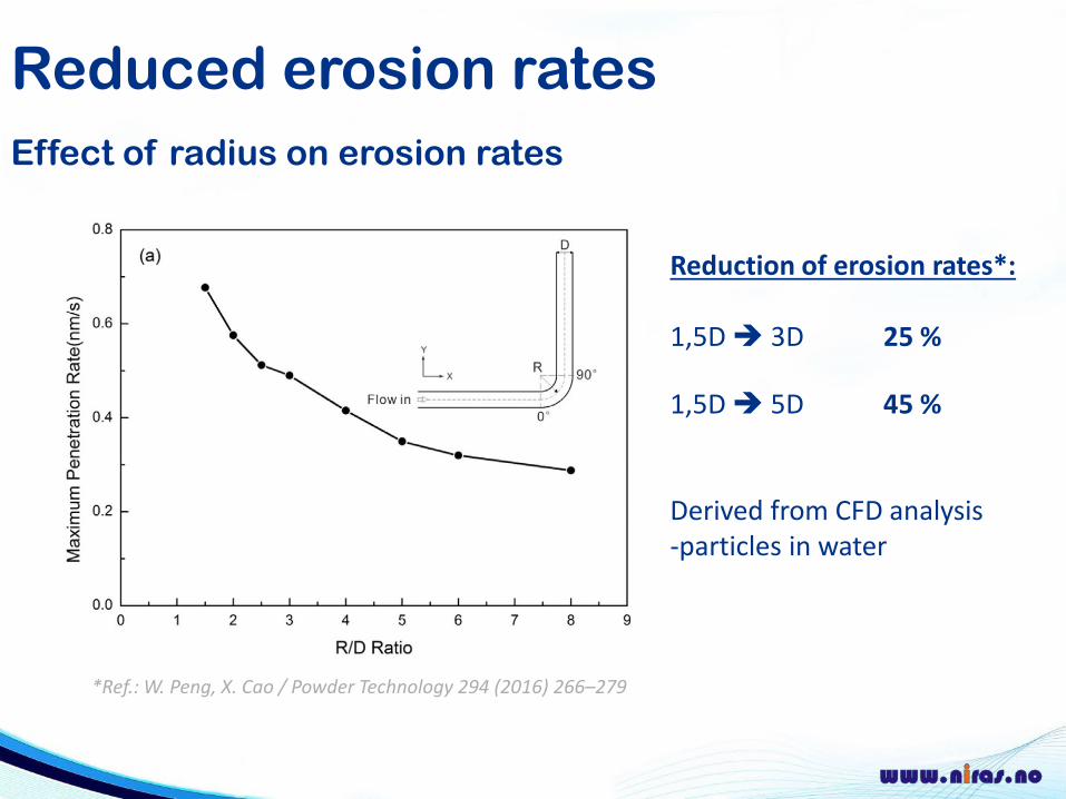
Reduced erosion ratesEffect of radius on erosion rates
Reduction of erosion rates*:
1,5D 3D 25 %
1,5D 5D 45 %
Derived from CFD analysis-particles in water
1 D 1,5 D 3 D
*Ref.: W. Peng, X. Cao / Powder Technology 294 (2016) 266–279
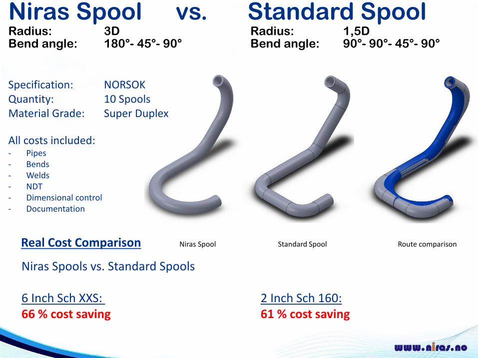
Niras Spool vs. Standard Spool Radius: 3D Radius: 1,5D Bend angle: 180°- 45°- 90° Bend angle: 90°- 90°- 45°- 90°
Specification: NORSOKQuantity: 10 SpoolsMaterial Grade: Super Duplex
All costs included:- Pipes- Bends- Welds- NDT- Dimensional control- Documentation
Real Cost Comparison Niras Spool Standard Spool Route comparison
Niras Spools vs. Standard Spools
6 Inch Sch XXS: 2 Inch Sch 160:66 % cost saving 61 % cost saving
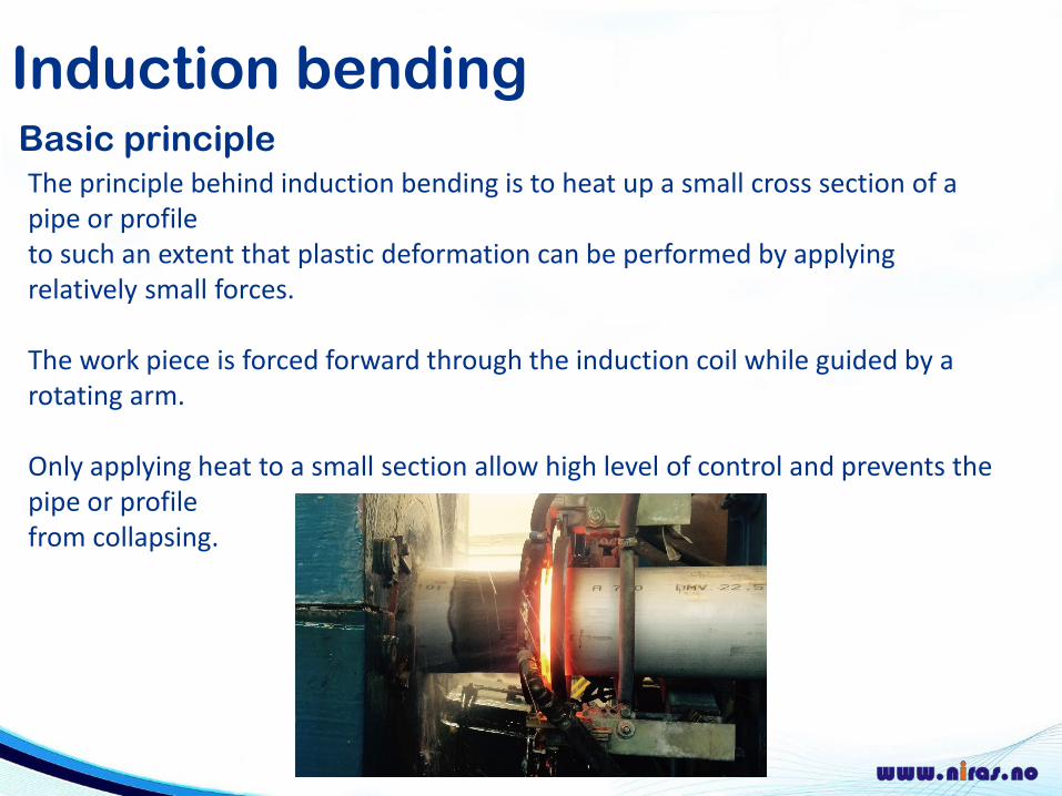
Induction bendingBasic principle The principle behind induction bending is to heat up a small cross section of a pipe or profile to such an extent that plastic deformation can be performed by applying relatively small forces.
The work piece is forced forward through the induction coil while guided by a rotating arm.
Only applying heat to a small section allow high level of control and prevents the pipe or profile from collapsing.
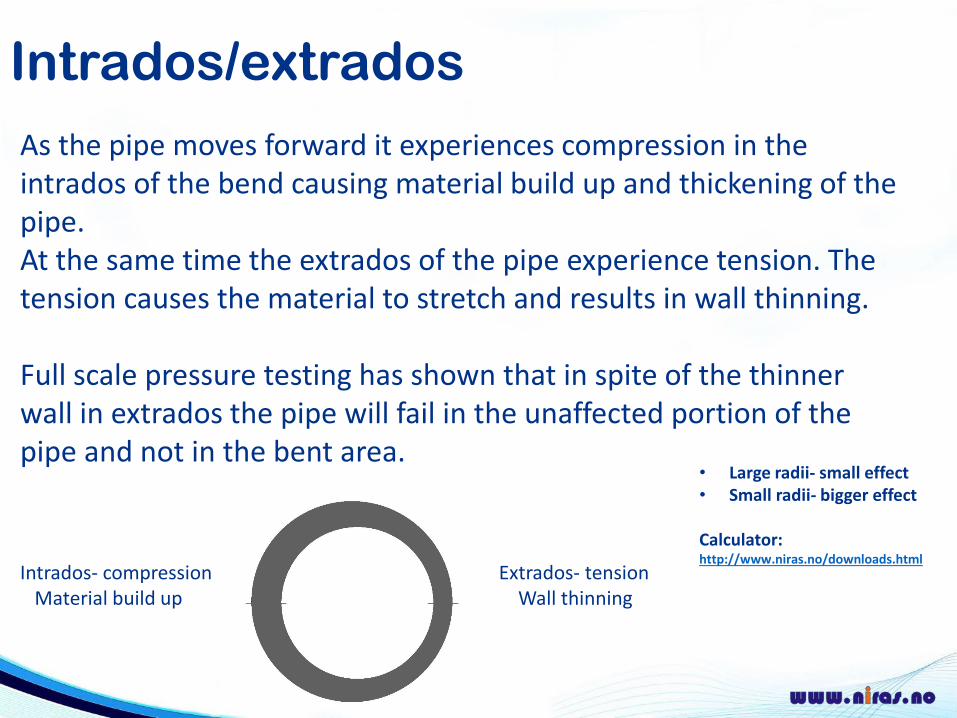
Intrados/extradosAs the pipe moves forward it experiences compression in the intrados of the bend causing material build up and thickening of the pipe.At the same time the extrados of the pipe experience tension. The tension causes the material to stretch and results in wall thinning.
Full scale pressure testing has shown that in spite of the thinner wall in extrados the pipe will fail in the unaffected portion of the pipe and not in the bent area.
Intrados- compression Extrados- tensionMaterial build up Wall thinning
• Large radii- small effect• Small radii- bigger effect
Calculator:http://www.niras.no/downloads.html
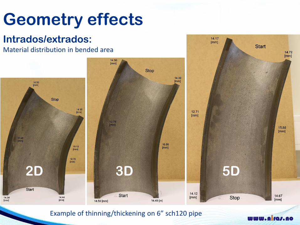
Geometry effectsIntrados/extrados:Material distribution in bended area
2D 3D 5D
Example of thinning/thickening on 6” sch120 pipe
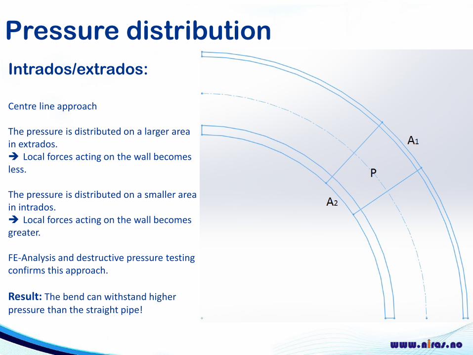
Pressure distributionIntrados/extrados:
Centre line approach
The pressure is distributed on a larger area in extrados. Local forces acting on the wall becomes less.
The pressure is distributed on a smaller area in intrados. Local forces acting on the wall becomes greater.
FE-Analysis and destructive pressure testingconfirms this approach.
Result: The bend can withstand higher pressure than the straight pipe!
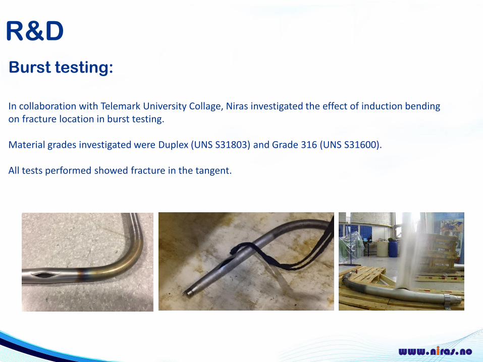
R&DBurst testing:
In collaboration with Telemark University Collage, Niras investigated the effect of induction bending on fracture location in burst testing.
Material grades investigated were Duplex (UNS S31803) and Grade 316 (UNS S31600).
All tests performed showed fracture in the tangent.
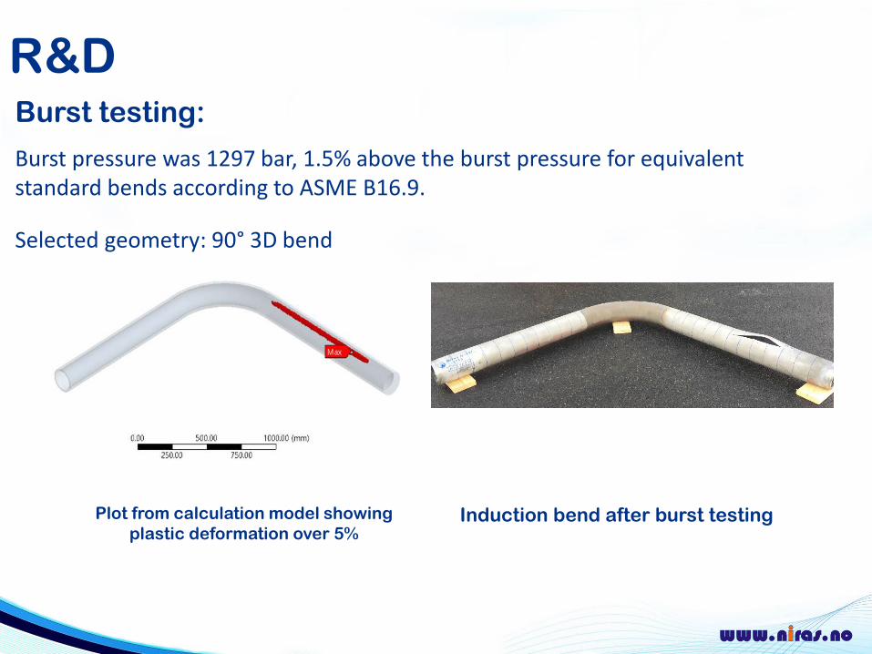
R&DBurst testing:
Burst pressure was 1297 bar, 1.5% above the burst pressure for equivalent standard bends according to ASME B16.9.
Selected geometry: 90° 3D bend
Induction bend after burst testingPlot from calculation model showingplastic deformation over 5%
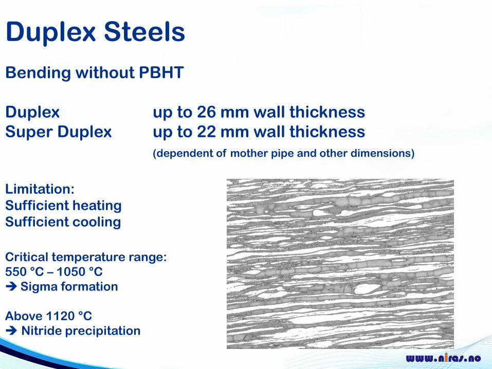
Duplex SteelsBending without PBHT
Duplex up to 26 mm wall thicknessSuper Duplex up to 22 mm wall thickness
(dependent of mother pipe and other dimensions)
Limitation:Sufficient heatingSufficient cooling
Critical temperature range: 550 °C – 1050 °CSigma formation
Above 1120 °C Nitride precipitation
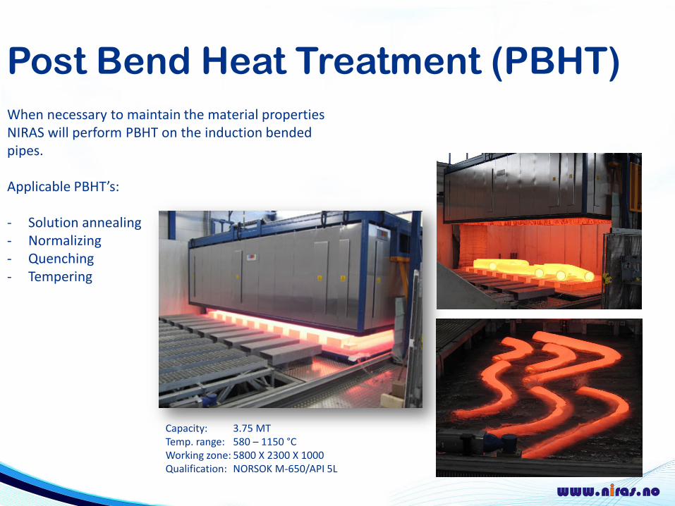
Post Bend Heat Treatment (PBHT)When necessary to maintain the material properties NIRAS will perform PBHT on the induction bended pipes.
Applicable PBHT’s:
- Solution annealing- Normalizing- Quenching - Tempering
Capacity: 3.75 MTTemp. range: 580 – 1150 °CWorking zone: 5800 X 2300 X 1000Qualification: NORSOK M-650/API 5L
Materials
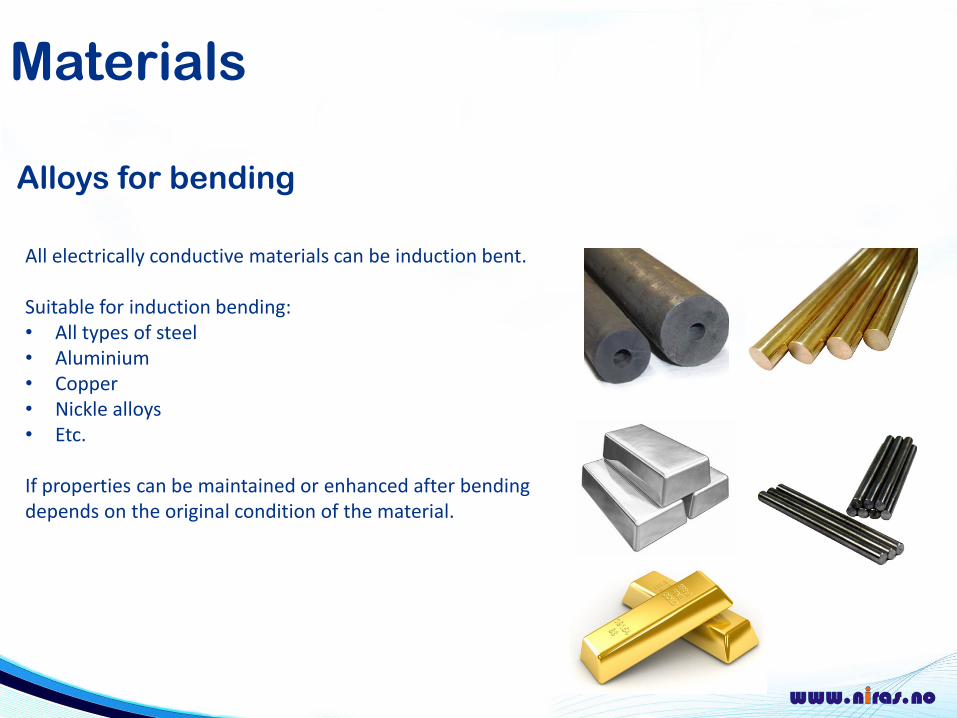
Alloys for bending
All electrically conductive materials can be induction bent.
Suitable for induction bending:• All types of steel• Aluminium • Copper• Nickle alloys• Etc.
If properties can be maintained or enhanced after bending depends on the original condition of the material.
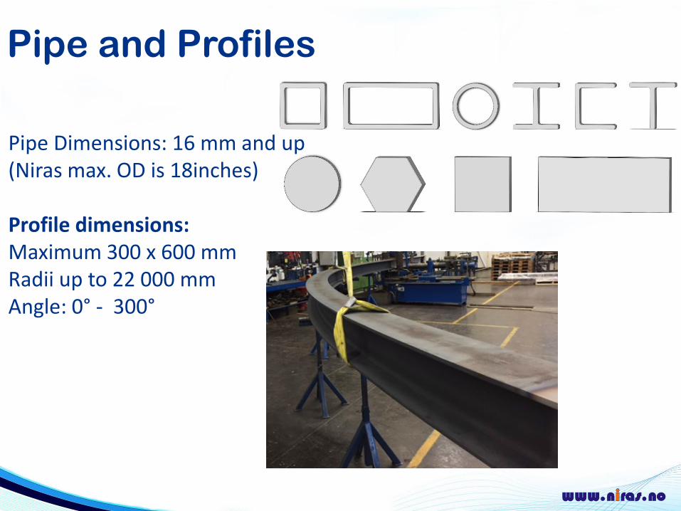
Pipe and Profiles
Pipe Dimensions: 16 mm and up(Niras max. OD is 18inches)
Profile dimensions: Maximum 300 x 600 mm Radii up to 22 000 mmAngle: 0° - 300°
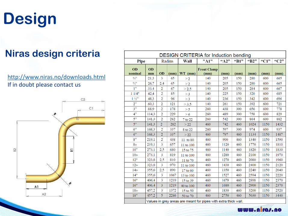
Design
Niras design criteria
http://www.niras.no/downloads.htmlIf in doubt please contact us
Commonly used
Doing it smart
Produce spools were possible Save cost of welding and procurement of standard bends.Reduces lead time due to fewer welding operations.
Send drafts and get valuable feedbackWe have long experience with routing to optimise for induction bending. Less bending – lower cost and lead time.
We do workshops with engineering companies on EPC projects from FEED and through-out to give input on how to best exploit the possibilities of the process.