Embed Size (px)
Citation preview
© 2011 WS8B
Propagation:
The science and study of radio wave reflection,
refraction, diffraction, absorption,
polarization, and scattering.
Hamvention®
Reuben Meeks, W8GUC
Electronics, R.F. Engineer,
Frank J. Beafore
WS8B – Technical Specialist, ARRL
© 2011 WS8B
Measurement Convention:
• Meter
• Centimeter
• Millimeter
• Hertz - Hz
• Kilohertz – KHz
• Megahertz – MHz
• Gigahertz – GHz
© 2011 WS8B
Propagation
Radio Wave Propagation
• Radio propagation is the behavior of radio waves when they are
transmitted, or propagated from one point on the Earth to another, or
into various parts of the atmosphere.
• Like light waves, radio waves are affected by the phenomena of
• reflection
refraction
diffraction
absorption
polarization
scattering
© 2011 WS8B
© 2010 WS8B
Early History
• 1850 – Fazio & Foucalt – Speed of Light
• 1852 - Gustav Kirchoff – Speed of Electricity
• 1853 – James Maxwell – Light = Electricity
• 1896 – Aleksandr Popov – Wireless Experiments
• 1899 – Nikola Tesla – First Antenna Theory
• 1901 – G. Marconi First Transatlantic Signal
© 2010 WS8B
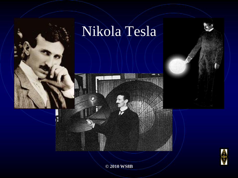
Nikola Tesla

© 2010 WS8B
The Tesla Coil
Please don’t
try this at
home.
© 2010 WS8B
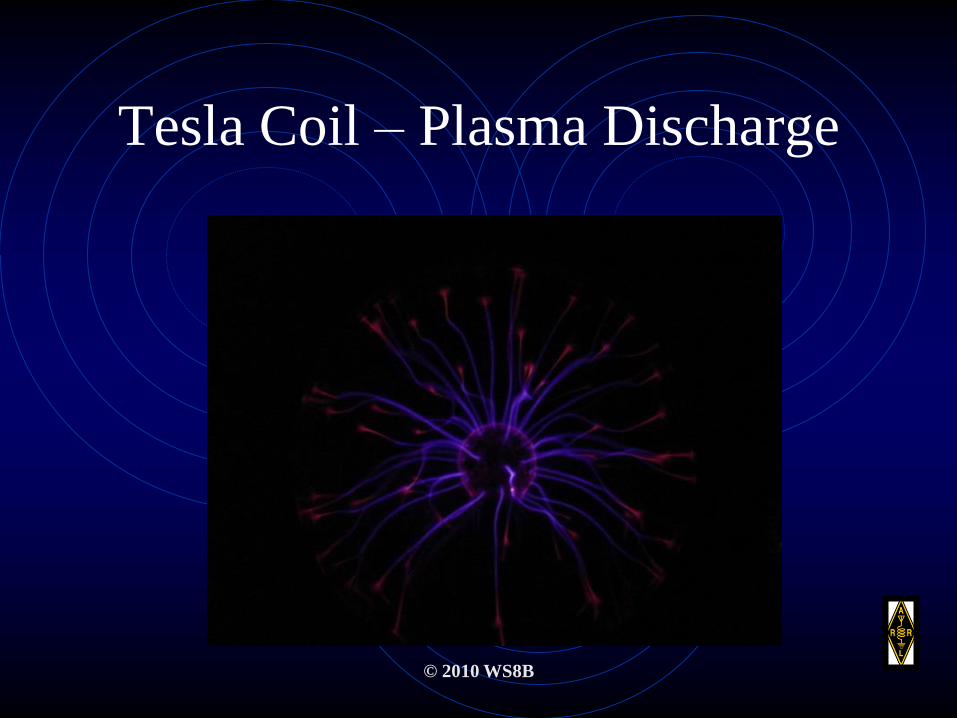
Tesla Coil – Plasma Discharge

© 2010 WS8B
Marconi,
Father of Radio

© 2010 WS8B
Antenna Definition
• “The antenna launches energy from a transmitter
into space or pulls it in from a passing wave for a
receiver. Without a suitable, properly installed
antenna, the best transmitter and receiver are
useless”.
Dr, John Kraus-W8JK, Professor Emeritus, Ohio
State University, Columbus, Ohio.
© 2010 WS8B
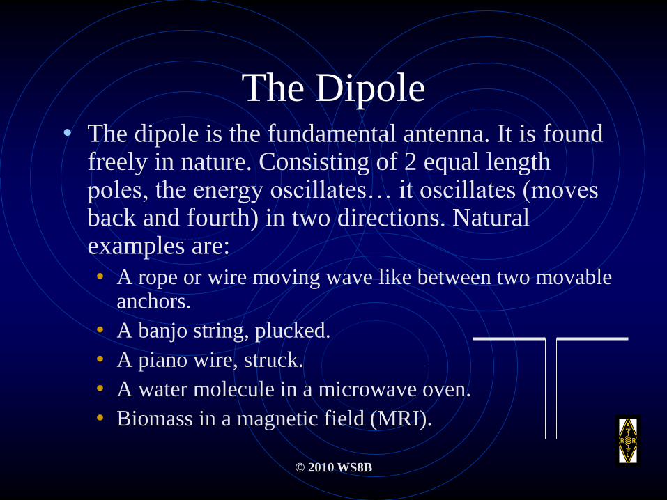
The Dipole• The dipole is the fundamental antenna. It is found
freely in nature. Consisting of 2 equal length poles, the energy oscillates… it oscillates (moves back and fourth) in two directions. Natural examples are:
• A rope or wire moving wave like between two movable anchors.
• A banjo string, plucked.
• A piano wire, struck.
• A water molecule in a microwave oven.
• Biomass in a magnetic field (MRI).
© 2010 WS8B
Wave formation
Waves are the result of energizing a “balanced” dipole system. This can be demonstrated by “waving” a rope, plucking a banjo string or striking a piano key.
© 2010 WS8B
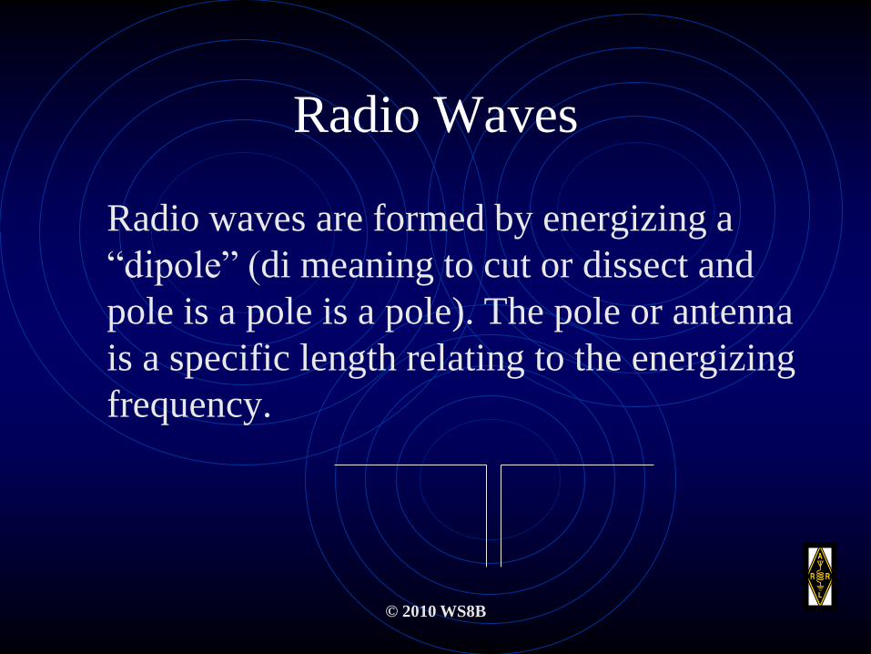
Radio Waves
Radio waves are formed by energizing a
“dipole” (di meaning to cut or dissect and
pole is a pole is a pole). The pole or antenna
is a specific length relating to the energizing
frequency.
© 2010 WS8B
Transmission and Reception
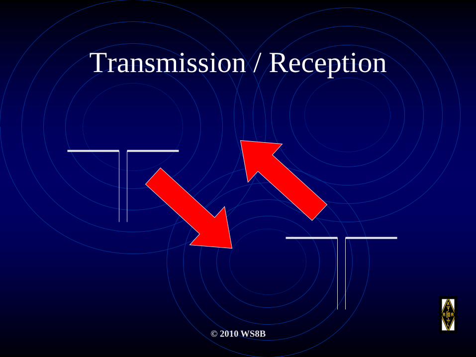
• Radio waves are emitted by an oscillating dipole
and escape into electromagnetic space much like
music from a piano that moves the air near it.
• The radio receiver detects the radio wave in a
manner similar to the human ear detecting a note
from a piano.
© 2010 WS8B
Transmission / Reception
© 2010 WS8B
Radio Spectrum
• As we discuss propagation, we will refer to various radio frequencies.
• These frequencies are generated by oscillators that vary in time.
• The mathematical occurrence of these frequencies are represented in order on a continuum or what is commonly called a spectrum.
• A rainbow is a spectrum of light frequencies acting on water molecules after a rain.
© 2010 WS8B
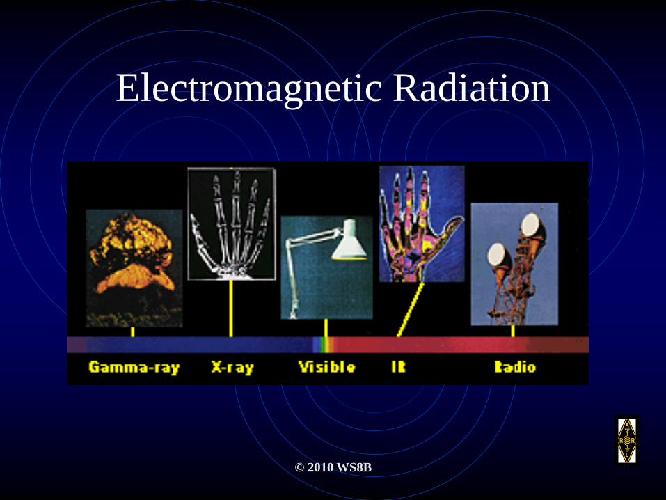
Electromagnetic Radiation
© 2010 WS8B
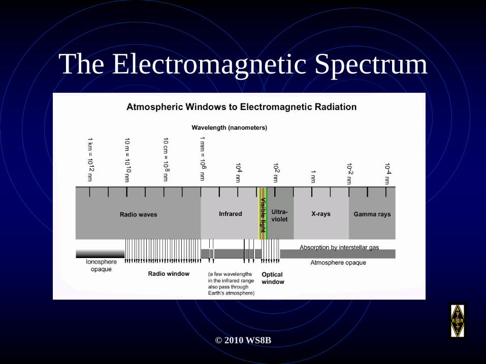
The Electromagnetic Spectrum
© 2010 WS8B
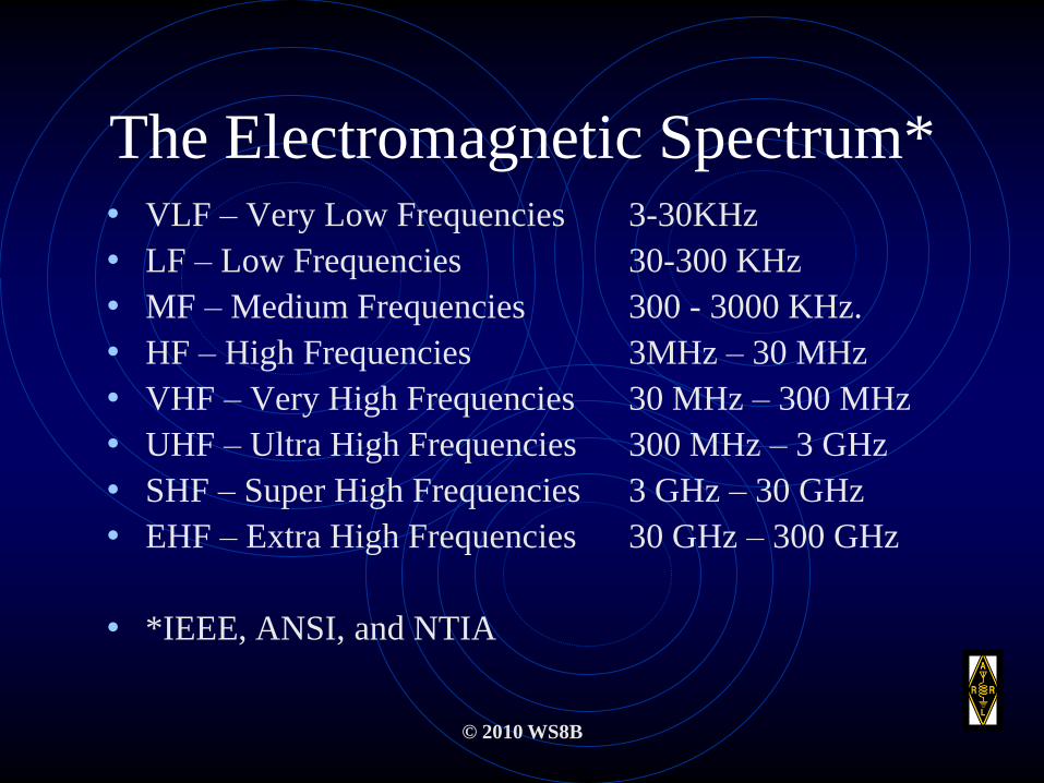
The Electromagnetic Spectrum*• VLF – Very Low Frequencies 3-30KHz
• LF – Low Frequencies 30-300 KHz
• MF – Medium Frequencies 300 - 3000 KHz.
• HF – High Frequencies 3MHz – 30 MHz
• VHF – Very High Frequencies 30 MHz – 300 MHz
• UHF – Ultra High Frequencies 300 MHz – 3 GHz
• SHF – Super High Frequencies 3 GHz – 30 GHz
• EHF – Extra High Frequencies 30 GHz – 300 GHz
• *IEEE, ANSI, and NTIA
© 2010 WS8B
Propagation
• Radio waves flow from the transmitter’s oscillating
antenna to the receiver's oscillating antenna but not always
directly
• Because radio waves travel in a Variety of ways to the
receiver, a knowledge of propagation is very important in
getting the most enjoyment of amateur radio.
© 2010 WS8B
Propagation: How Signals Travel
• When dealing with radio signals, Transmission –
Reception takes 3 forms:
• Line of Sight
• Ground Wave
• Sky-Wave
© 2010 WS8B
Line of Sight Propagation
• The simplest form of propagation is line of site. All frequencies will function in this form.
• Distance between the transmitter and receiver is dependent on the frequency / wavelength of the signal.
• Line of site propagation is very useful at VHF and UHF Frequencies.
© 2010 WS8B
Ground Wave Propagation
• This form of propagation fits most frequencies but
the distance between the transmitter and receiver
will vary with geography and composition of
“ground”.
• A good example of very different “grounds” is the
difference between the desert and the ocean.

© 2010 WS8B
Sky Wave Propagation
• This form of propagation is influenced by many
chemical and physical phenomena.
• Sky wave propagation results in communications
covering our entire globe.

© 2010 WS8B
Sky Wave Propagation
© NASA
© 2010 WS8B
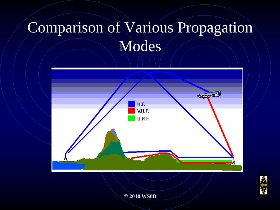
Comparison of Various Propagation
Modes
© 2010 WS8B
Sky-Wave Propagation
• Otherwise known as “skip” is primarily due to the
ionization of the earths upper atmosphere.
• This part of the atmosphere is known as:
ionization + atmosphere = Ionosphere.
© 2010 WS8B
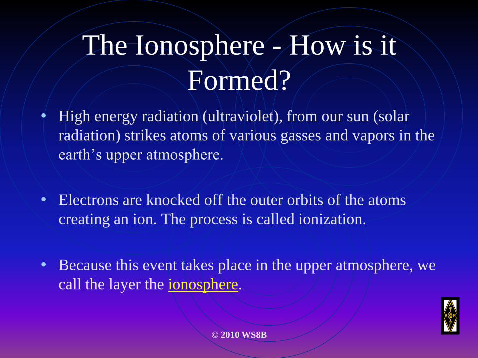
The Ionosphere - How is it
Formed?• High energy radiation (ultraviolet), from our sun (solar
radiation) strikes atoms of various gasses and vapors in the
earth’s upper atmosphere.
• Electrons are knocked off the outer orbits of the atoms
creating an ion. The process is called ionization.
• Because this event takes place in the upper atmosphere, we
call the layer the ionosphere.

© 2010 WS8B
Solar Activity
• Solar activity has the most effect on sky-wave propagation.
• Solar activity is a function of sunspot occurrence.
• With increased activity, long-distance communication in
the HF and VHF range is enhanced.
© 2010 WS8B
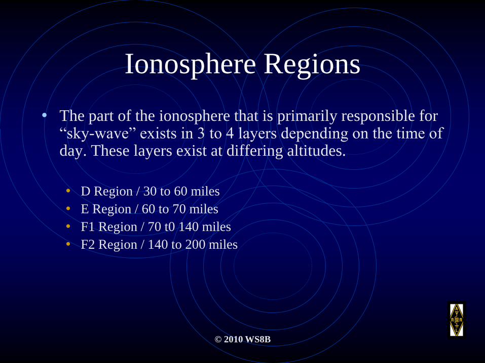
Ionosphere Regions
• The part of the ionosphere that is primarily responsible for “sky-wave” exists in 3 to 4 layers depending on the time of day. These layers exist at differing altitudes.
• D Region / 30 to 60 miles
• E Region / 60 to 70 miles
• F1 Region / 70 t0 140 miles
• F2 Region / 140 to 200 miles

© 2010 WS8B
Propagation at Selected Layers
• D Region: Closest to the earth and least ionized and is responsible for short hop HF communication.
• E Region: Daylight absorption of MF and HF. Can be useful for single hop HF out to 1200 miles. VHF skip can exist with “sporadic E” (more later).
• F Region: Most responsible for DX. In the daytime, this layer splits into two parts: F1 and F2. After sunset, this layer combines into one. The F2 Region is primarily responsible for long hops or skip to 2500 miles. F2 reaches its maximum height at noon during the summer.
© 2011 WS8B
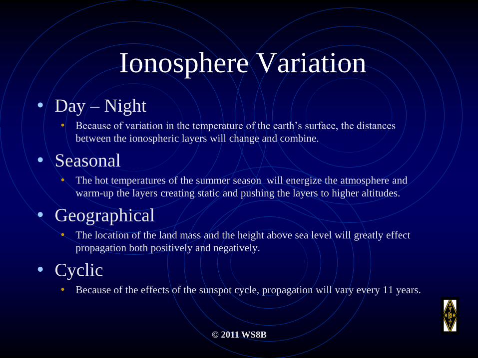
Ionosphere Variation
• Day – Night• Because of variation in the temperature of the earth’s surface, the distances
between the ionospheric layers will change and combine.
• Seasonal• The hot temperatures of the summer season will energize the atmosphere and
warm-up the layers creating static and pushing the layers to higher altitudes.
• Geographical• The location of the land mass and the height above sea level will greatly effect
propagation both positively and negatively.
• Cyclic• Because of the effects of the sunspot cycle, propagation will vary every 11 years.
© 2010 WS8B
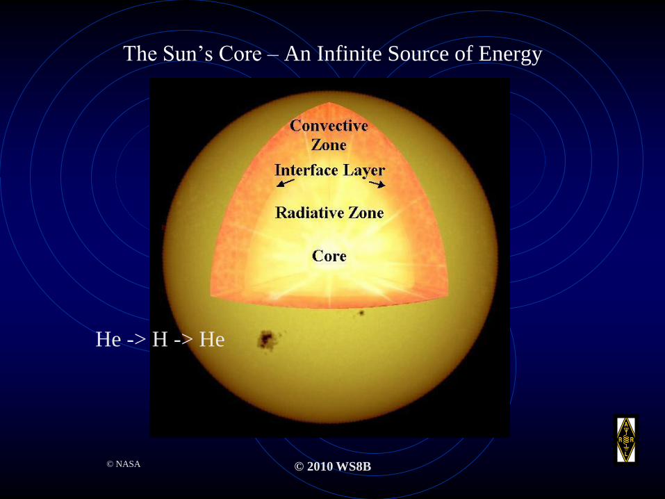
The Sun’s Core – An Infinite Source of Energy
© NASA
He -> H -> He

© 2010 WS8B
Solar Flux
• Because of the tremendous amount of energy produced by the sun, the sun emits radio waves on all frequencies.
• The radio wave emission is called Solar Flux.
• The solar flux is measured at specific frequencies and reported as the Solar-Flux Index.
© 2010 WS8B
Ionosphere Disturbances
• Sunspot Cycle
• Solar Flare’s
• SID’s – Sudden Ionosphere Disturbances
• Ionosphere Storms
• Polar Blackout

© 2010 WS8B
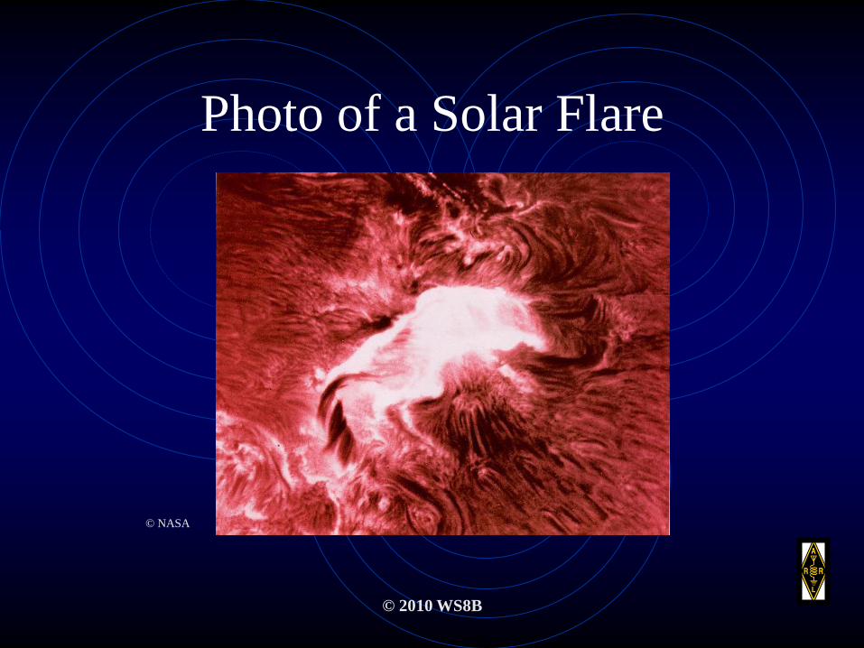
Solar Flare
• A solar flare is a burst of energy emitted from the sun’s
surface going out into space thousands of miles.
• A solar flare can emit intense UV radiation hitting the
earth within 8 minutes after the event. Particles from the
flare arrive in the earth’s upper atmosphere from an hour to
about 2 days later.

© 2010 WS8B
Solar Flare / Eclipse of the Sun
© NASA
Solar Flare
© 2010 WS8B
Photo of a Solar Flare
© NASA
© 2010 WS8B
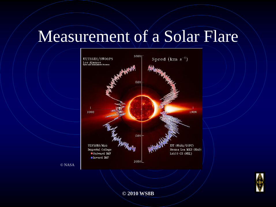
Measurement of a Solar Flare
© NASA
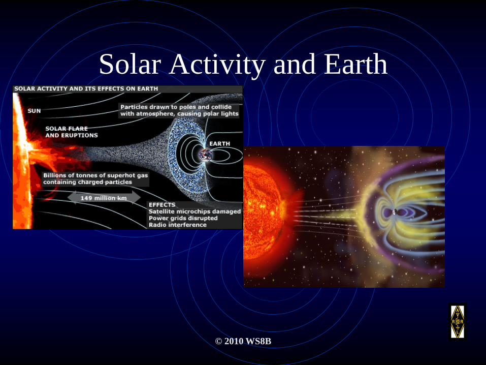
Solar Activity and Earth
© 2010 WS8B
Sunspots
© 2011 WS8B

© 2010 WS8B
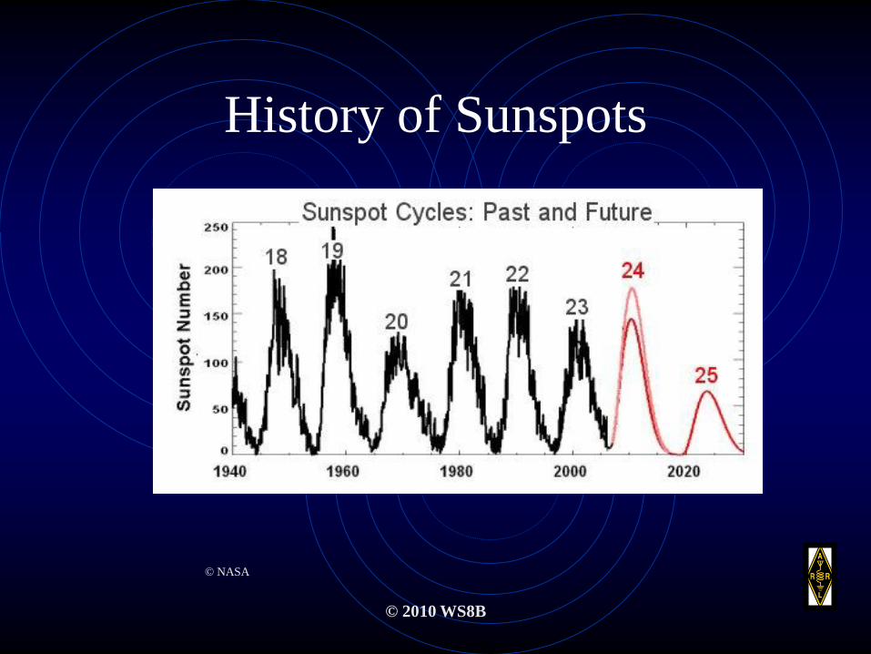
Sunspots Occurrence
• Sunspot maxima occurs on an average of every 11
years.
• Even though data has been recorded on sunspot
activity for over 250 years, the cause for the
phenomena is not yet known.
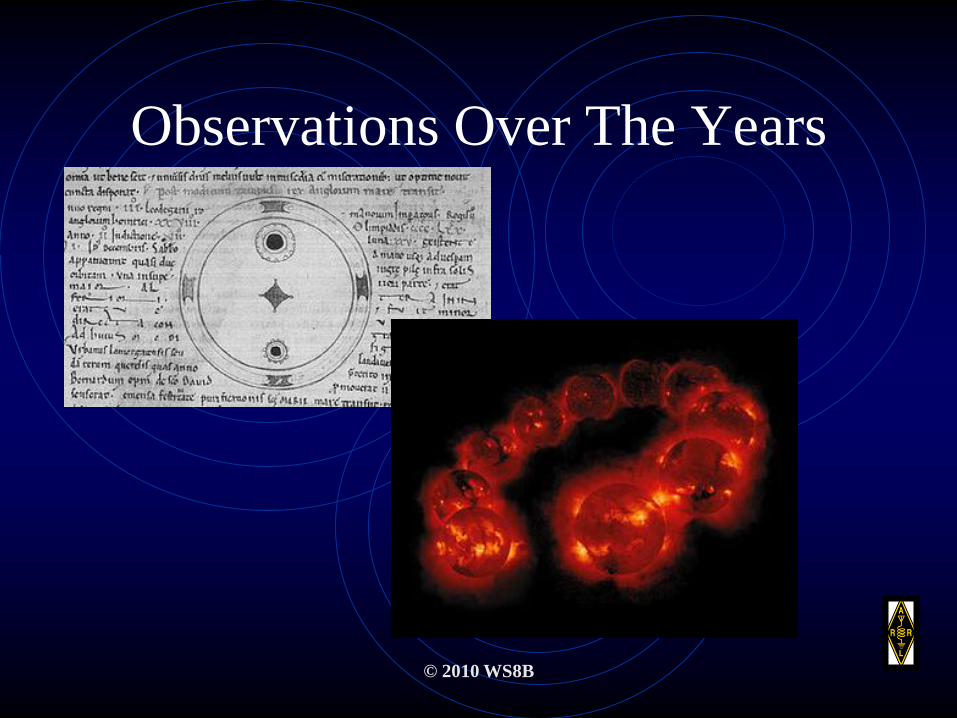
Observations Over The Years
© 2010 WS8B
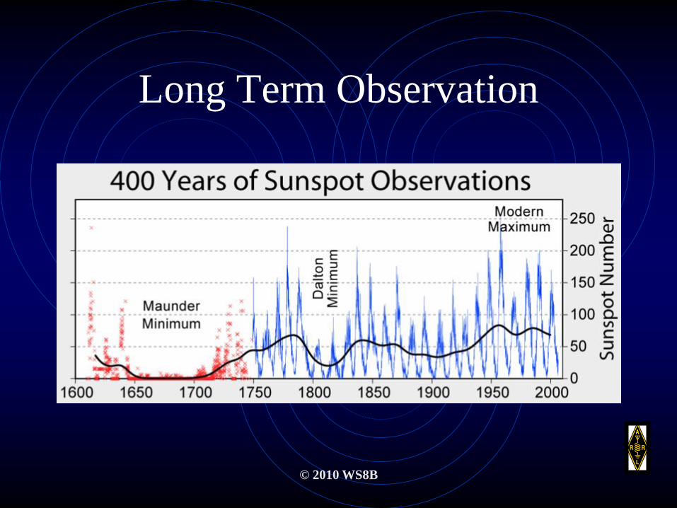
Long Term Observation
© 2010 WS8B
© 2010 WS8B
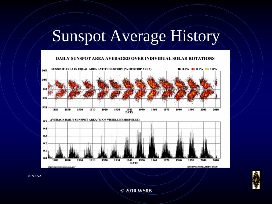
Sunspot Average History
© NASA
© 2010 WS8B
History of Sunspots
© NASA
© 2010 WS8B
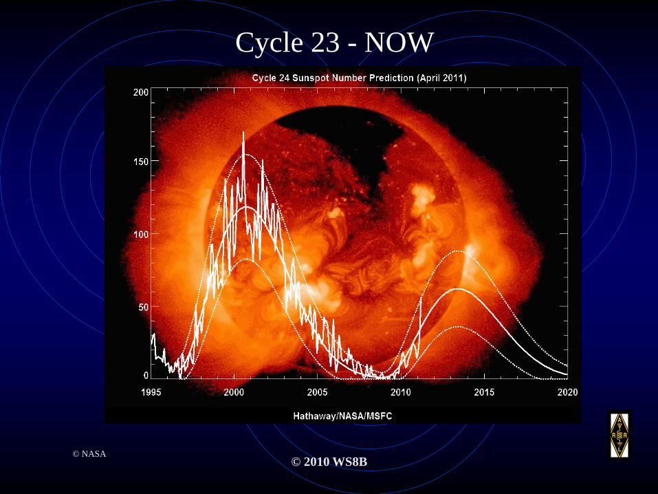
Cycle 23 - NOW
© NASA
Relative Sunspot Number• A measure of sunspot activity, computed from the formula:
• R = k(10g + f),
• where R is the relative sunspot number,
• f the number of individual spots,
• g the number of groups of spots,
• and k a factor that varies with the observer (his or her personal equation),
• the seeing, and the observatory (location and instrumentation). Also known as
sunspot number; sunspot relative number; Wolf number; Wolf-Wolfer
number; Zurich number.
Read more: http://www.answers.com/topic/relative-sunspot-
number#ixzz1LrgBvA10© 2010 WS8B
© 2010 WS8B
Sudden Ionosphere Disturbance
(SID)• A SID is a blackout of HF sky wave communications that
occurs after a solar flair.
• A large amount of UV radiation leaves the sun at the speed
of light and arrives 8 minutes later.
• The D-Layer rapidly becomes a radio wave absorber.
Depending on the “attack” angle, a SID could last from a
few minutes to a few hours.
© 2010 WS8B
Geomagnetic Disturbance
• A dramatic change in the earth’s magnetic field
over a short period of time results in a
geomagnetic disturbance.
• These usually occur in areas greater than 45
degrees latitude.
© 2010 WS8B
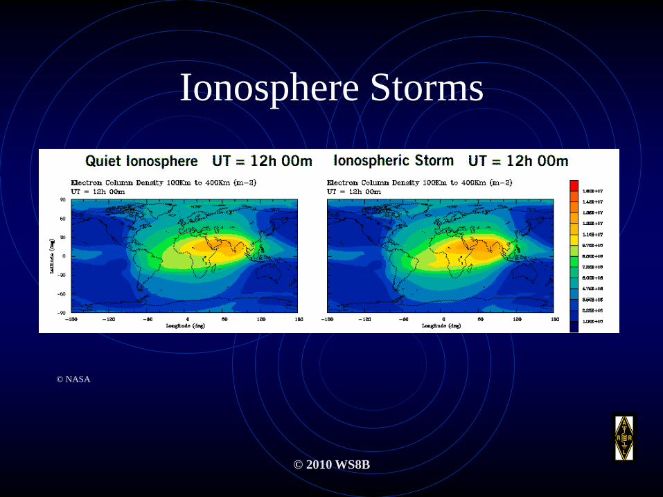
Ionosphere Storms
© NASA
© 2010 WS8B
Propagation in the HF Bands
• Without ionization of the atmosphere
due to the sun’s energy, HF propagation
would be limited to line of site.
© 2010 WS8B
Propagation on the VHF Bands
• VHF propagation is principally line of site but much
longer paths are possible with e-layer phenomena.
• Ionization of the atmosphere due to re-entry of meteors
will also create a condition for VHF long distance
propagation.
• One new method of long distance VHF communication
results from bouncing VHF signals off high altitude
commercial airliners.
© 2010 WS8B
Propagation on the UHF Bands
• UHF propagation is basically line of site. Some long range
propagation is possible with E-Layer phenomena.
• UHF is used mainly for local communication. Sometimes
UHF can be part of a wide area repeater system allowing
for interstate communication.
© 2010 WS8B
MUF – Maximum Usable
Frequency
• Maximum Usable Frequency (MUF) is defined as the upper limit of
available frequencies for a given atmospheric situation.
• MUF can be approximately measured by monitoring bacon stations at
or near the frequency in question.
• In the U.S., 4 beacons are available from the National Bureau of
Standards. Three are also available from the Canadian Government.
Many private beacons are available (see internet).
© 2010 WS8B
Government Beacon Frequencies
Available:
• 3.330Mhz - CHU
• 4.670MHz - CHU
• 5 MHz – NBS (WWVH)
• 7.850MHz - CHU
• 10MHz – NBS
• 15MHz – NBS
• 20MHz – NBS
© 2010 WS8B
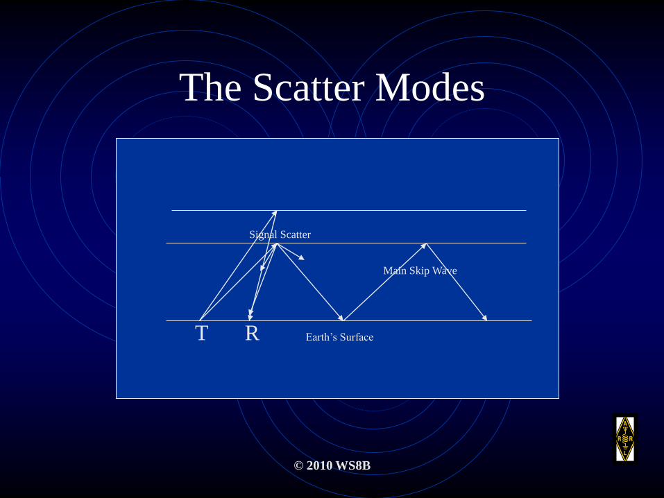
The Scatter Modes
Main Skip Wave
Signal Scatter
Earth’s SurfaceT R
© 2010 WS8B
Characteristics of Scattered
Signals
• Too Far for Ground Wave – Too Near for Sky Wave
• A Wavering Sound Due to Multiple Arrivals of the Signal
• The Sound Is Distorted Due to Multiple Path Signals
• Usually, Received Signals Are Weak
© 2010 WS8B
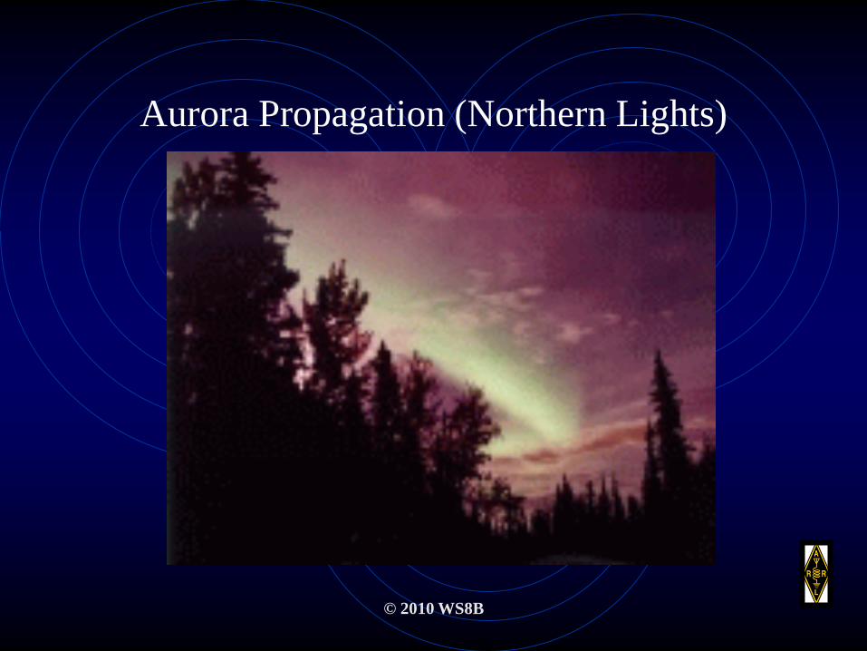
Aurora Propagation (Northern Lights)
© 2010 WS8B
Aurora Propagation
• A beautiful display of ionized clouds in the northern hemisphere called the Aurora Borealis is also propagation enhancing.
• The Aurora is formed by ionized gasses in the upper atmosphere being concentrated by the earth’s magnetic poles.
• This mode supports great propagation on 50 and 144 MHz.

© 2010 WS8B
Sporadic “E”
• Sporadic E is the ionization of the E layer of the ionosphere.
• It occurs most predominately during June and July in the
North American Hemisphere.
• It concentrates in the frequency range of 50 MHz but is
responsible for improved propagation on 28MHz and
144MHz.
© 2010 WS8B
Sporadic “E” (Cont.)
• The cause of sporadic E is not completely known, but the most popular theory relates to wind shear at 100km altitude.
• When this occurs, E reflections are almost “mirror-like” and can result on spectacular DX on QRP – especially on VHF and UHF.
• Monitoring distant NOAA weather stations is a good way to measure it’s occurrence.

© 2010 WS8B
Troposphere Bending and
Ducting• The troposphere is the part of the atmosphere that is closest
to the earth.
• VHF / UHF radio waves are known to travel beyond the
horizon while following the troposphere.
• The troposphere can be “radio enhanced” with thermal
inversions forming “ducts” in which VHF / UHF waves
pass through moving signals up to 2500 miles.
© 2010 WS8B
Path Loss Trough The
Troposphere
• The path loss increases with higher
frequencies.
• Low VHF = Lowest Loss
• Medium VHF = Medium Loss
• UHF = Highest Loss
© 2010 WS8B
Effects Of The Weather
• The Seasons
• The Clouds
• Lightning
• Rain
• Snow
• Fog
The Seasons
• Summer, Fall, Winter and Spring have an effect
on propagation.
• This is emphasized with the length of daylight
(amount of ionizing sunlight).
• Also, the hot air of the summer and the cold air of
winter changes the air density as well as the
heights of the ionosphere regions (D, E, F1 and
F2).
© 2010 WS8B
The Clouds
• Obviously, clouds can be massive. They contain large
amounts of water and can either be your friend of foe w/r
to radio propagation.
• In some cases the cloud blocks signals from reaching
destination. In other cases, cloud formations “rub” while
going in opposite directions causing ionization between
them creating a reflecting zone.
© 2010 WS8B

Lightning
• Lightning is a byproduct of differentiated
charges between objects – cloud to cloud,
cloud to ground, cloud to conducting objects.
• Lightning can cause significant electrical noise
thus determining signal effeteness.
© 2010 WS8B

Rain• Rain, being predominately made of water is
also a dipole molecule. If you get enough
rain within the radio wave path, it will
greatly reduce the signal.
• On the other hand, rain being a dipole can
be used as a reflector thus enhancing the
signal.
© 2010 WS8B
Snow
• Snow provides interesting propagation
phenomena. Because of it’s water make-up, snow
also exhibits some of the same characteristics of
rain and fog.
• Depending on temperature, snow can be very dry
and under the correct conditions, create a
tremendous amount of static electricity.
© 2010 WS8B

Fog
• Fog is water vapor. It is usually formed close to
the ground due to differentiated atmospheric
temperatures.
• Fog properties are much like clouds, however
nearby fog can be very debilitating in the
UHF/VHF frequency range
© 2010 WS8B
© 2010 WS8B
Summary
• Radio communication has 4 basic building blocks – The transmitter,
The receiver the antenna and the medium in which the radio wave
travels.
• Understanding these 4 building blocks is important in achieving
communication beyond line of site.
• The causes and effects of radio propagation continues to remain a
mystery.
• Understanding the make-up of the phenomena of propagation will
greatly enhance the excitement of Radio Communication.
Questions and Dialog
• Open for questions
• Hearing none will provoke a quiz!!!
• Not passing, will cause you to drop down
one license level!!!!
© 2011 WS8B
© 2010 WS8B
Thank You
de:W8GUC and WS8B