Embed Size (px)
Citation preview
The SLS Optics Beamline
U. Flechsig∗, R. Abela∗, R. Betemps∗, H. Blumer∗, K. Frank†, A. Jaggi∗, A. A.MacDowell†, H. A. Padmore†, V. Schönherr∗, J. Ulrich∗, H. Walther∗, S. Zelenika∗∗
and C. Zumbach∗
∗Paul Scherrer Institut, Swiss Light Source, 5232 Villigen PSI, Switzerland† Lawrence Berkeley National Laboratory, Advanced Light Source, MS 2-400, 1 Cyclotron Road, Berkeley, CA
94720, USA∗∗Department of Machine Design, University of Rijeka, Vukovarska 58, 51000 Rijeka, Croatia
Abstract. A multipurpose beamline for tests and developments in the field of x-ray optics and synchrotron radiation in-strumentation in general is under construction at the Swiss Light Source (SLS) bending magnet X05DA. The beamlineuses a newly developed UHV compatible, 100 µm thick, brazed CVD diamond vacuum window. The very compact cryo-genicly cooled channel cut Si(111) monochromator and bendable 1:1 toroidal focusing mirror at 7.75m from the sourcepoint are installed inside the shielding tunnel. The beamline covers a photon energy range of about 6 to 17 keV. We expect5 ·1011 photons/s within a 100 µm spot and a resolving power of 1300. The monochromator and focusing mirror can beretracted independently for unfocused monochromatic and focused "white" light operation respectively.
Keywords: synchrotron radiation, beamline optics, channel cut monochromator, cryogenic coolingPACS: 07.85.Qe, 42.79.Dj
INTRODUCTION
The SLS optics beamline has been planned to allow quick beam access for instrumentation tests and developments inthe field of optics or detectors, feasibility experiments and training of operators and students. We aimed for maximumflexibility and balanced performance. We chose a design which is basically a copy of the x-ray diffraction beamline atthe Advanced Light Source (ALS BL 11.3.1.) [1, 2]. The characteristic features of the beamline are the very compact1
assembly of a cryogenicly cooled channel cut Si(111) monochromator, a slit system and a bendable 1:1 toroidalfocusing mirror carried by a single support structure. The complete assembly is installed inside the radiation shieldingof the storage ring. The installation close to the source point combines a relative high angular acceptance with compactsize of the crystal and mirror and allows a 1:1 focusing in both directions with one toroidal mirror2. The evidentdrawback coming from the limited access times to the storage ring tunnel can be restricted to an acceptable level withreliable remote control and excellent survey, alignment and extensive testing. This has been successfully demonstratedat the ALS.
The main components for the beamline are delivered, characterization measurements of the mechanics are underway. The front end parts, vacuum window and support structure are already installed at the final position. Theinstallation of the monochromator and mirror unit is scheduled for June 2006.
CVD DIAMOND VACUUM WINDOW
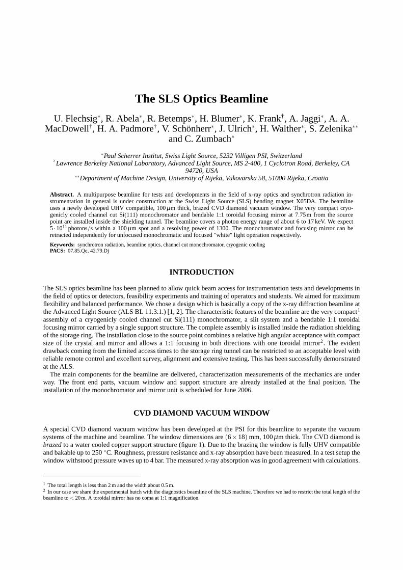
A special CVD diamond vacuum window has been developed at the PSI for this beamline to separate the vacuumsystems of the machine and beamline. The window dimensions are (6×18) mm, 100 µm thick. The CVD diamond isbrazed to a water cooled copper support structure (figure 1). Due to the brazing the window is fully UHV compatibleand bakable up to 250 ◦C. Roughness, pressure resistance and x-ray absorption have been measured. In a test setup thewindow withstood pressure waves up to 4 bar. The measured x-ray absorption was in good agreement with calculations.
1 The total length is less than 2 m and the width about 0.5 m.2 In our case we share the experimental hutch with the diagnostics beamline of the SLS machine. Therefore we had to restrict the total length of thebeamline to < 20m. A toroidal mirror has no coma at 1:1 magnification.
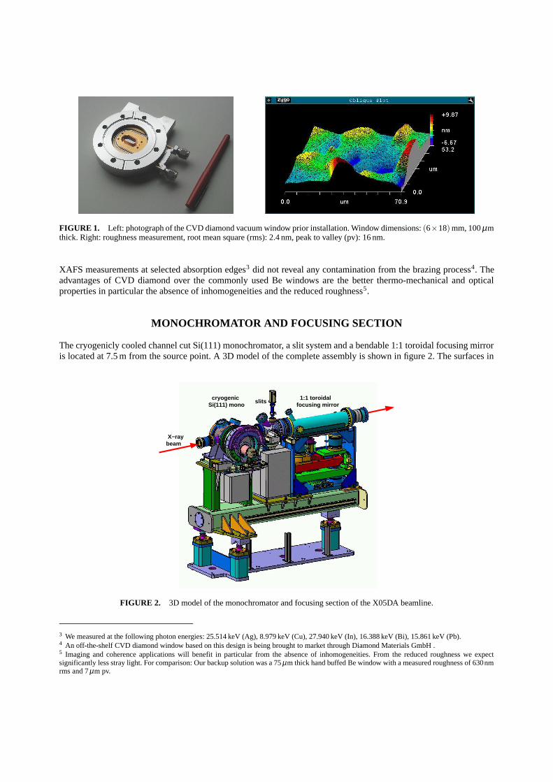
FIGURE 1. Left: photograph of the CVD diamond vacuum window prior installation. Window dimensions: (6×18) mm, 100 µmthick. Right: roughness measurement, root mean square (rms): 2.4 nm, peak to valley (pv): 16 nm.
XAFS measurements at selected absorption edges3 did not reveal any contamination from the brazing process4. Theadvantages of CVD diamond over the commonly used Be windows are the better thermo-mechanical and opticalproperties in particular the absence of inhomogeneities and the reduced roughness5.
MONOCHROMATOR AND FOCUSING SECTION
The cryogenicly cooled channel cut Si(111) monochromator, a slit system and a bendable 1:1 toroidal focusing mirroris located at 7.5 m from the source point. A 3D model of the complete assembly is shown in figure 2. The surfaces in
slitsSi(111) mono
cryogenic 1:1 toroidalfocusing mirror
beamX−ray
FIGURE 2. 3D model of the monochromator and focusing section of the X05DA beamline.
3 We measured at the following photon energies: 25.514 keV (Ag), 8.979 keV (Cu), 27.940 keV (In), 16.388 keV (Bi), 15.861 keV (Pb).4 An off-the-shelf CVD diamond window based on this design is being brought to market through Diamond Materials GmbH .5 Imaging and coherence applications will benefit in particular from the absence of inhomogeneities. From the reduced roughness we expectsignificantly less stray light. For comparison: Our backup solution was a 75 µm thick hand buffed Be window with a measured roughness of 630nmrms and 7 µm pv.
transverse stage theta stage
cryo cooler
x−rays in bearingbellow
vertical stage
bender
tilt/ yaw stage
mirror clamps
compensation bellows
cooling blades
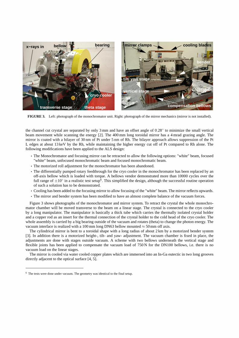
FIGURE 3. Left: photograph of the monochromator unit. Right: photograph of the mirror mechanics (mirror is not installed).
the channel cut crystal are separated by only 3 mm and have an offset angle of 0.28◦ to minimize the small verticalbeam movement while scanning the energy [2]. The 400 mm long toroidal mirror has a 4 mrad grazing angle. Themirror is coated with a bilayer of 30 nm of Pt under 5 nm of Rh. The bilayer approach allows suppression of the PtL edges at about 13 keV by the Rh, while maintaining the higher energy cut off of Pt compared to Rh alone. Thefollowing modifications have been applied to the ALS design:
• The Monochromator and focusing mirror can be retracted to allow the following options: "white" beam, focused"white" beam, unfocused monochromatic beam and focused monochromatic beam.
• The motorized roll adjustment for the monochromator has been abandoned.• The differentially pumped rotary feedthrough for the cryo cooler in the monochromator has been replaced by an
off-axis bellow which is loaded with torque. A bellows vendor demonstrated more than 10000 cycles over thefull range of ±10◦ in a realistic test setup6. This simplified the design, although the successful routine operationof such a solution has to be demonstrated.
• Cooling has been added to the focusing mirror to allow focusing of the "white" beam. The mirror reflects upwards.• The mirror and bender system has been modified to have an almost complete balance of the vacuum forces.
Figure 3 shows photographs of the monochromator and mirror system. To retract the crystal the whole monochro-mator chamber will be moved transverse to the beam on a linear stage. The crystal is connected to the cryo coolerby a long manipulator. The manipulator is basically a thick tube which carries the thermally isolated crystal holderand a copper rod as an insert for the thermal connection of the crystal holder to the cold head of the cryo cooler. Thewhole assembly is carried by a big bearing outside of the vacuum and rotates (theta) to change the photon energy. Thevacuum interface is realized with a 100 mm long DN63 bellow mounted ≈ 50mm off axis.
The cylindrical mirror is bent to a toroidal shape with a long radius of about 2 km by a motorized bender system[3]. In addition there is a motorized height-, tilt- and yaw- adjustment. The vacuum chamber is fixed in place, theadjustments are done with stages outside vacuum. A scheme with two bellows underneath the vertical stage andflexible joints has been applied to compensate the vacuum load of 750 N for the DN100 bellows, i.e. there is novacuum load on the linear stages.
The mirror is cooled via water cooled copper plates which are immersed into an In-Ga eutectic in two long groovesdirectly adjacent to the optical surface [4, 5].
6 The tests were done under vacuum. The geometry was identical to the final setup.
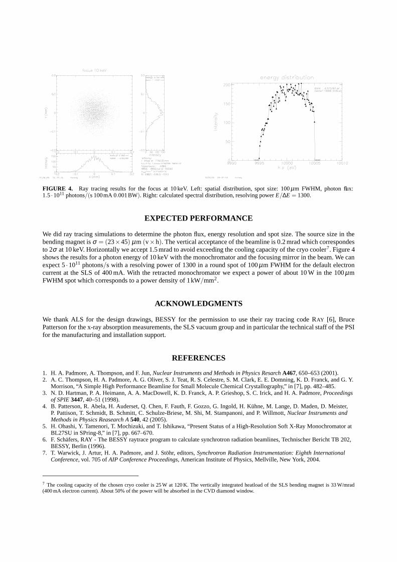
FIGURE 4. Ray tracing results for the focus at 10 keV. Left: spatial distribution, spot size: 100 µm FWHM, photon flux:1.5 ·1011 photons/(s 100mA 0.001BW). Right: calculated spectral distribution, resolving power E/∆E = 1300.
EXPECTED PERFORMANCE
We did ray tracing simulations to determine the photon flux, energy resolution and spot size. The source size in thebending magnet is σ = (23×45) µm (v×h). The vertical acceptance of the beamline is 0.2 mrad which correspondesto 2σ at 10 keV. Horizontally we accept 1.5 mrad to avoid exceeding the cooling capacity of the cryo cooler7. Figure 4shows the results for a photon energy of 10 keV with the monochromator and the focusing mirror in the beam. We canexpect 5 ·1011 photons/s with a resolving power of 1300 in a round spot of 100 µm FWHM for the default electroncurrent at the SLS of 400 mA. With the retracted monochromator we expect a power of about 10 W in the 100 µmFWHM spot which corresponds to a power density of 1kW/mm2.
ACKNOWLEDGMENTS
We thank ALS for the design drawings, BESSY for the permission to use their ray tracing code RAY [6], BrucePatterson for the x-ray absorption measurements, the SLS vacuum group and in particular the technical staff of the PSIfor the manufacturing and installation support.
REFERENCES
1. H. A. Padmore, A. Thompson, and F. Jun, Nuclear Instruments and Methods in Physics Resarch A467, 650–653 (2001).2. A. C. Thompson, H. A. Padmore, A. G. Oliver, S. J. Teat, R. S. Celestre, S. M. Clark, E. E. Domning, K. D. Franck, and G. Y.
Morrison, “A Simple High Performance Beamline for Small Molecule Chemical Crystallography,” in [7], pp. 482–485.3. N. D. Hartman, P. A. Heimann, A. A. MacDowell, K. D. Franck, A. P. Grieshop, S. C. Irick, and H. A. Padmore, Proceedings
of SPIE 3447, 40–51 (1998).4. B. Patterson, R. Abela, H. Auderset, Q. Chen, F. Fauth, F. Gozzo, G. Ingold, H. Kühne, M. Lange, D. Maden, D. Meister,
P. Pattison, T. Schmidt, B. Schmitt, C. Schulze-Briese, M. Shi, M. Stampanoni, and P. Willmott, Nuclear Instruments andMethods in Physics Reasearch A 540, 42 (2005).
5. H. Ohashi, Y. Tamenori, T. Mochizuki, and T. Ishikawa, “Present Status of a High-Resolution Soft X-Ray Monochromator atBL27SU in SPring-8,” in [7], pp. 667–670.
6. F. Schäfers, RAY - The BESSY raytrace program to calculate synchrotron radiation beamlines, Technischer Bericht TB 202,BESSY, Berlin (1996).
7. T. Warwick, J. Artur, H. A. Padmore, and J. Stöhr, editors, Synchrotron Radiation Instrumentation: Eighth InternationalConference, vol. 705 of AIP Conference Proceedings, American Institute of Physics, Mellville, New York, 2004.
7 The cooling capacity of the chosen cryo cooler is 25 W at 120 K. The vertically integrated heatload of the SLS bending magnet is 33 W/mrad(400 mA electron current). About 50% of the power will be absorbed in the CVD diamond window.