Embed Size (px)
Citation preview
www.klsmartin.com
L1® MI Orthognathics The Solution for Minimally Invasive Orthognathic Surgery
Oral and maxillo-facial surgery is our passion! Its further development, together with our customers, is our ambition. Every day we work on developing innovative products and services which meet the highest demands on quality, and which contribute to the wellbeing of the patient.
L1® MI Orthognathics | Instruments for Minimally Invasive Orthognathic Surgery
3
Pages
L1® MI Orthognathics – the Concept 4-5
Product Features 6-15
Indications and Surgical Techniques 16-45
■ MI Le Fort I Osteotomy 18-29
■ MI Sagittal Split Osteotomy 30-37
■ MI Chin Osteotomy 38-45
Product Range
■ Instruments 46-63
■ Storage 64-65
■ Recommended Set Configuration 66-67
■ Standard Implants 68-69
Table of Contents
4
L1® MI Orthognathics | Instruments for Minimally Invasive Orthognathic Surgery
5
Orthognathic surgery is a key element of oral and maxillofacial surgery, so in the relevant clinics and practices it takes place almost every day.
Congenital or acquired dysgnathia is a phenomenon that is not uncommon –about one in ten are affected. Dysgnathia is usually accompanied by disharmony of facial appearance and functional impairment.
Elimination of skeletal discrepancies by corrective orthognathic surgery can achieve functional improvements of occlusion, respiration and airway.
The IPS CaseDesigner® makes 3D virtual surgical planning easier and faster than ever before. With this flexible software tool, planning and simulating surgical interventions become efficient and reliable.
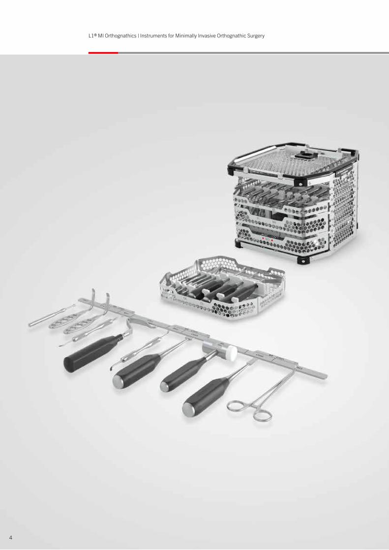
L1® MI Orthognathics comprises of instruments and implants that were specially developed for minimally invasive orthognathic surgery. Consequently, the user has at his or her disposal a standardized solution for MI Le Fort I, MI Sagittal Split and MI Chin osteotomy. To ensure a safe and reproducible procedure the instruments are arranged using sequence templates and then they are used step by step.
The entire procedure is based on Prof. Swennen's many years of experience.Maxillofacial and Facial Plastic Surgery, AZ St-Jan, Bruges, Belgium.
L1® MI Orthognathics The Concept
6
L1® MI Orthognathics | Product Features
Feature – Function – Benefit
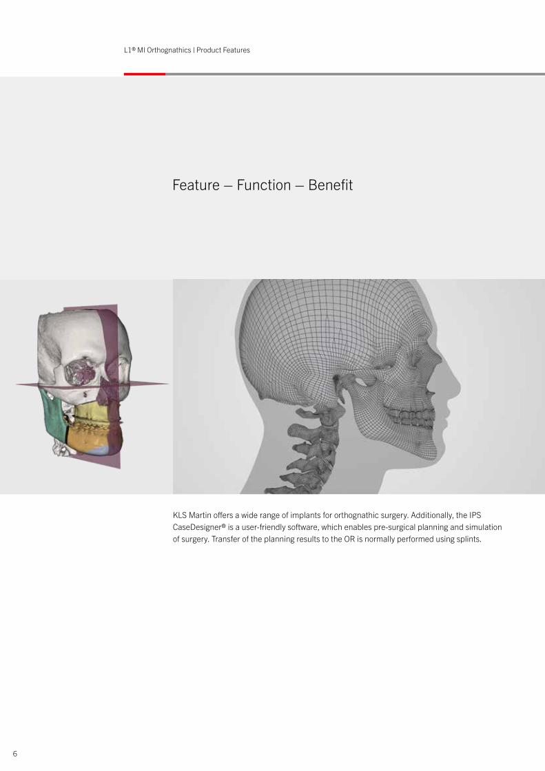
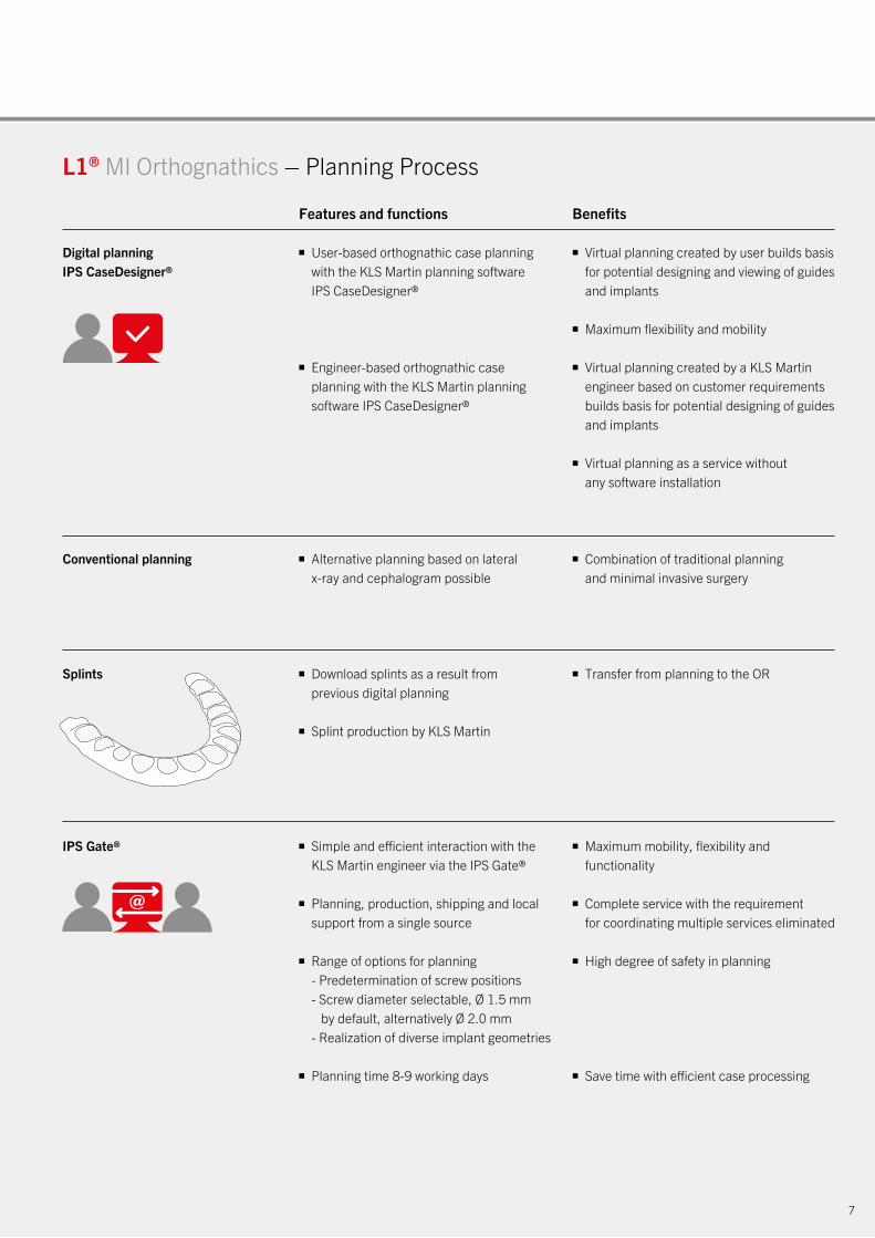
KLS Martin offers a wide range of implants for orthognathic surgery. Additionally, the IPS CaseDesigner® is a user-friendly software, which enables pre-surgical planning and simulation of surgery. Transfer of the planning results to the OR is normally performed using splints.
7
■ User-based orthognathic case planning with the KLS Martin planning software IPS CaseDesigner®
■ Engineer-based orthognathic case planning with the KLS Martin planning software IPS CaseDesigner®
■ Download splints as a result from previous digital planning
■ Splint production by KLS Martin
■ Simple and efficient interaction with the KLS Martin engineer via the IPS Gate®
■ Planning, production, shipping and local support from a single source
■ Range of options for planning - Predetermination of screw positions - Screw diameter selectable, Ø 1.5 mm by default, alternatively Ø 2.0 mm - Realization of diverse implant geometries
■ Planning time 8-9 working days
■ Alternative planning based on lateral x-ray and cephalogram possible
Digital planningIPS CaseDesigner®
Splints
IPS Gate®
Conventional planning
■ Virtual planning created by user builds basis for potential designing and viewing of guides and implants
■ Maximum flexibility and mobility
■ Virtual planning created by a KLS Martin engineer based on customer requirements builds basis for potential designing of guides and implants
■ Virtual planning as a service without any software installation
■ Transfer from planning to the OR
■ Maximum mobility, flexibility and functionality
■ Complete service with the requirement for coordinating multiple services eliminated
■ High degree of safety in planning
■ Save time with efficient case processing
■ Combination of traditional planning and minimal invasive surgery
L1® MI Orthognathics – Planning Process
Features and functions Benefits
xxx
xxx
xxx
xxx
888
L1® MI Orthognathics | Product Features
Feature – Function – Benefit
Mx1
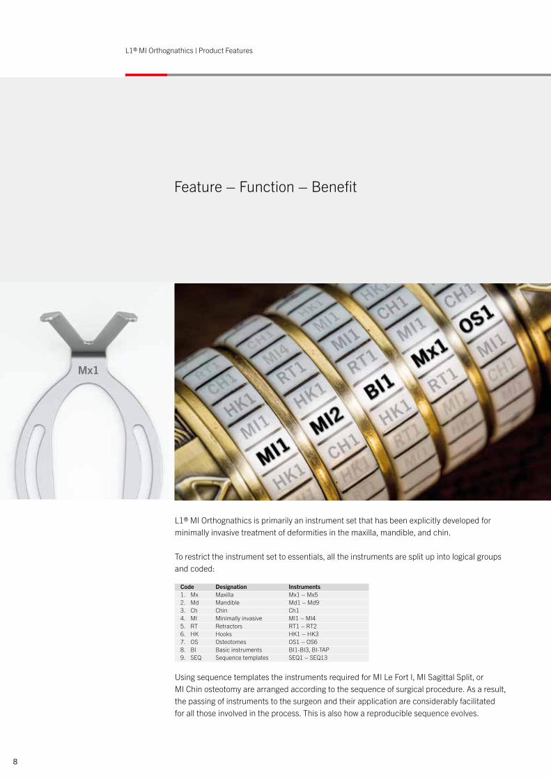
L1® MI Orthognathics is primarily an instrument set that has been explicitly developed for minimally invasive treatment of deformities in the maxilla, mandible, and chin.
To restrict the instrument set to essentials, all the instruments are split up into logical groups and coded:
Using sequence templates the instruments required for MI Le Fort I, MI Sagittal Split, or MI Chin osteotomy are arranged according to the sequence of surgical procedure. As a result, the passing of instruments to the surgeon and their application are considerably facilitated for all those involved in the process. This is also how a reproducible sequence evolves.
Code Designation Instruments1. Mx Maxilla Mx1 – Mx52. Md Mandible Md1 – Md93. Ch Chin Ch14. MI Minimally invasive MI1 – MI45. RT Retractors RT1 – RT26. HK Hooks HK1 – HK37. OS Osteotomes OS1 – OS6 8. BI Basic instruments BI1-BI3, BI-TAP 9. SEQ Sequence templates SEQ1 – SEQ13
99
3
3
3
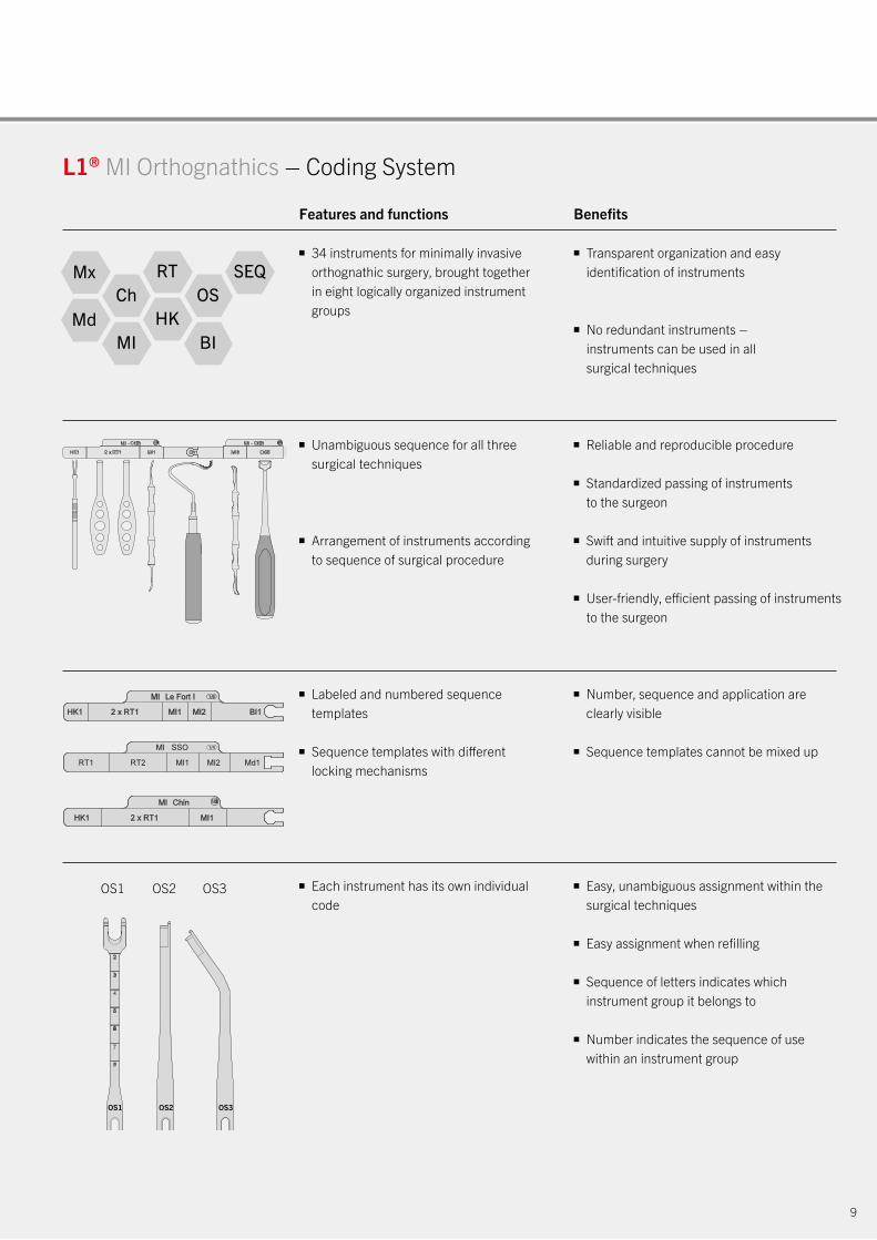
■ 34 instruments for minimally invasive orthognathic surgery, brought together in eight logically organized instrument groups
■ Unambiguous sequence for all three surgical techniques
■ Arrangement of instruments according to sequence of surgical procedure
■ Labeled and numbered sequence templates
■ Sequence templates with different locking mechanisms
■ Each instrument has its own individual code
OS1 OS2 OS3
■ Transparent organization and easy identification of instruments
■ No redundant instruments – instruments can be used in all surgical techniques
■ Reliable and reproducible procedure
■ Standardized passing of instruments to the surgeon
■ Swift and intuitive supply of instruments during surgery
■ User-friendly, efficient passing of instruments to the surgeon
■ Number, sequence and application are clearly visible
■ Sequence templates cannot be mixed up
■ Easy, unambiguous assignment within the surgical techniques
■ Easy assignment when refilling
■ Sequence of letters indicates which instrument group it belongs to
■ Number indicates the sequence of use within an instrument group
L1® MI Orthognathics – Coding System
Features and functions Benefits
OS1 OS2 OS3
MxCh
SEQOS
RT
MdMI BI
HK
10
xxx
xxx
xxx
xxx
L1® MI Orthognathics | Product Features
Feature – Function – Benefit
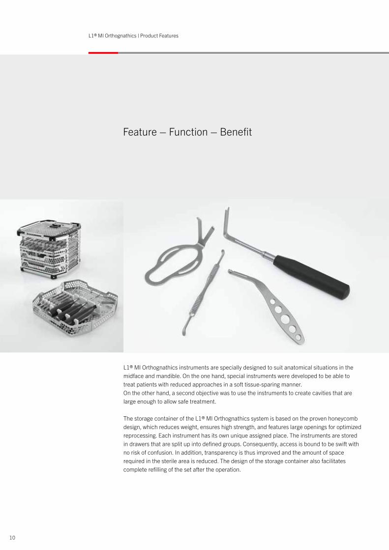
L1® MI Orthognathics instruments are specially designed to suit anatomical situations in the midface and mandible. On the one hand, special instruments were developed to be able to treat patients with reduced approaches in a soft tissue-sparing manner. On the other hand, a second objective was to use the instruments to create cavities that are large enough to allow safe treatment.
The storage container of the L1® MI Orthognathics system is based on the proven honeycomb design, which reduces weight, ensures high strength, and features large openings for optimized reprocessing. Each instrument has its own unique assigned place. The instruments are stored in drawers that are split up into defined groups. Consequently, access is bound to be swift with no risk of confusion. In addition, transparency is thus improved and the amount of space required in the sterile area is reduced. The design of the storage container also facilitates complete refilling of the set after the operation.

11
L1® MI Orthognathics – Instruments and Storage Containers
■ 34 instruments specially developed for - MI Le Fort I osteotomy - MI Sagittal Split osteotomy - MI Chin osteotomy
■ Specially designed to suit anatomical situations in the midface and mandible
■ Atraumatic design
■ Functional handle design with different handle sizes
■ Standardized handle design within the instrument groups
■ Stainless steel storage containers of honeycomb design combined with high-performance plastic
■ Stackable mesh trays
■ Instruments stored in six coded drawer modules
■ Drawer bottom with laser images and article numbers
■ Minimal incisions and reduced approaches
■ Rapid patient reconvalescence
■ Perfect passing of instruments to the surgeon within the created cavities
■ Soft tissue-sparing
■ Facilitates use with appropriate amount of effort
■ Same haptics for similar instruments
■ Transparent and standardized appearance
■ High strength, light weight
■ Easy to rinse out due to large openings
■ Minimal space requirement in the OR
■ Reliable reprocessing
■ Transparent, space-saving storage
■ Swift, systematic access
■ Space-saving direct access from the front
■ For easy refilling
■ For easy reordering
Features and functions Benefits
38-684-44-04
xxx
xxx
xxx
xxx
12
L1® MI Orthognathics | Product Features
Feature – Function – Benefit
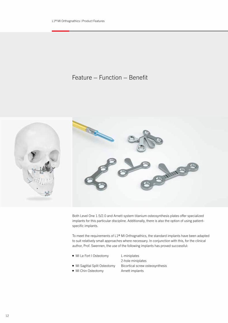
Both Level One 1.5/2.0 and Arnett system titanium osteosynthesis plates offer specialized implants for this particular discipline. Additionally, there is also the option of using patient- specific implants.
To meet the requirements of L1® MI Orthognathics, the standard implants have been adapted to suit relatively small approaches where necessary. In conjunction with this, for the clinical author, Prof. Swennen, the use of the following implants has proved successful:
■ MI Le Fort I Osteotomy L-miniplates 2-hole miniplates■ MI Sagittal Split Osteotomy Bicortical screw osteosynthesis■ MI Chin Osteotomy Arnett implants
xxxyv xxx
HK1 RT1 RT1 MI1 Ch1 MI3 OS5 BI-TAP OS6 BI3L1® MI Orthognathics – MI Chin Surgical Codes and Sequence
13
MI Chin osteotomy
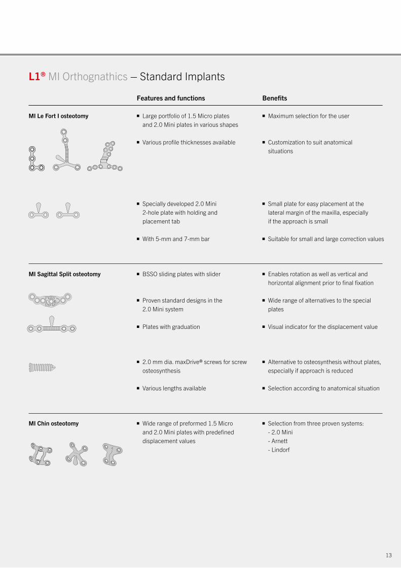
L1® MI Orthognathics – Standard Implants
MI Le Fort I osteotomy ■ Large portfolio of 1.5 Micro plates and 2.0 Mini plates in various shapes
■ Various profile thicknesses available
■ Specially developed 2.0 Mini 2-hole plate with holding and placement tab
■ With 5-mm and 7-mm bar
■ BSSO sliding plates with slider
■ Proven standard designs in the 2.0 Mini system
■ Plates with graduation
■ 2.0 mm dia. maxDrive® screws for screw osteosynthesis
■ Various lengths available
■ Wide range of preformed 1.5 Micro and 2.0 Mini plates with predefined displacement values
■ Maximum selection for the user
■ Customization to suit anatomical situations
■ Small plate for easy placement at the lateral margin of the maxilla, especially if the approach is small
■ Suitable for small and large correction values
■ Enables rotation as well as vertical and horizontal alignment prior to final fixation
■ Wide range of alternatives to the special plates
■ Visual indicator for the displacement value
■ Alternative to osteosynthesis without plates, especially if approach is reduced
■ Selection according to anatomical situation
■ Selection from three proven systems: - 2.0 Mini - Arnett - Lindorf
MI Sagittal Split osteotomy
Features and functions Benefits
D
50-304-0350-302-03 50-300-0450-304-0350-302-03 50-300-0450-304-0350-302-03 50-300-04
Feature – Function – Benefit
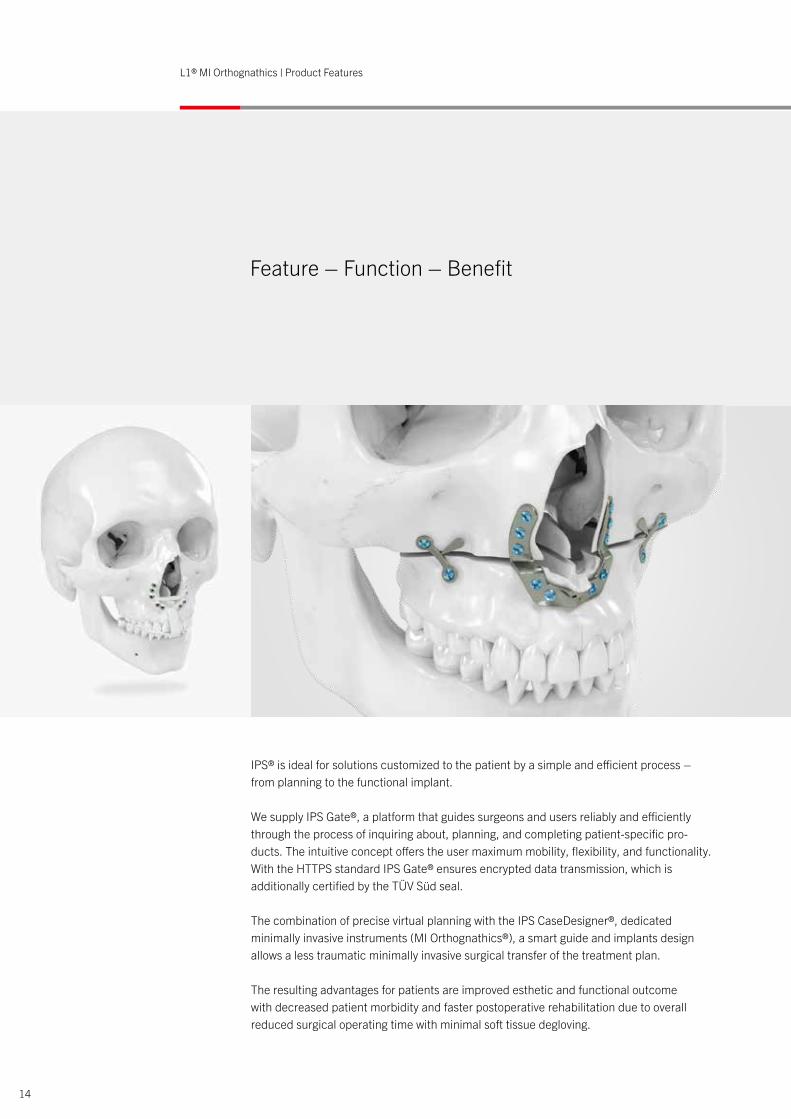
IPS® is ideal for solutions customized to the patient by a simple and efficient process – from planning to the functional implant.
We supply IPS Gate®, a platform that guides surgeons and users reliably and efficiently through the process of inquiring about, planning, and completing patient-specific pro-ducts. The intuitive concept offers the user maximum mobility, flexibility, and functionality. With the HTTPS standard IPS Gate® ensures encrypted data transmission, which is additionally certified by the TÜV Süd seal.
The combination of precise virtual planning with the IPS CaseDesigner®, dedicatedminimally invasive instruments (MI Orthognathics®), a smart guide and implants design allows a less traumatic minimally invasive surgical transfer of the treatment plan. The resulting advantages for patients are improved esthetic and functional outcomewith decreased patient morbidity and faster postoperative rehabilitation due to overall reduced surgical operating time with minimal soft tissue degloving.
14
L1® MI Orthognathics | Product Features
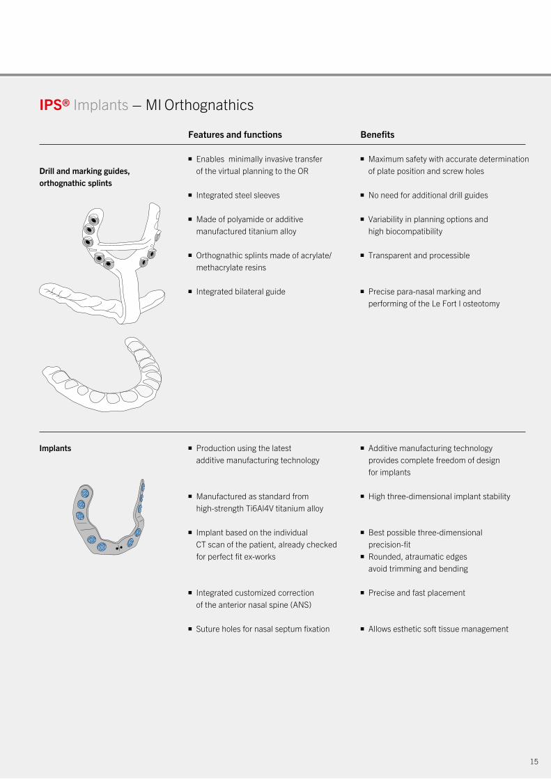
Implants
■ Enables minimally invasive transfer of the virtual planning to the OR
■ Integrated steel sleeves
■ Made of polyamide or additive manufactured titanium alloy
■ Orthognathic splints made of acrylate/ methacrylate resins
■ Integrated bilateral guide
■ Production using the latest additive manufacturing technology
■ Manufactured as standard from high-strength Ti6Al4V titanium alloy
■ Implant based on the individual CT scan of the patient, already checked for perfect fit ex-works
■ Integrated customized correction of the anterior nasal spine (ANS)
■ Suture holes for nasal septum fixation
■ Maximum safety with accurate determination of plate position and screw holes
■ No need for additional drill guides
■ Variability in planning options and high biocompatibility
■ Transparent and processible
■ Precise para-nasal marking and performing of the Le Fort I osteotomy
■ Additive manufacturing technology provides complete freedom of design for implants
■ High three-dimensional implant stability
■ Best possible three-dimensional precision-fit ■ Rounded, atraumatic edges avoid trimming and bending
■ Precise and fast placement
■ Allows esthetic soft tissue management
IPS® Implants – MI Orthognathics
Drill and marking guides, orthognathic splints
Features and functions Benefits
15
16
L1® MI Orthognathics | Indications and Surgical Technique
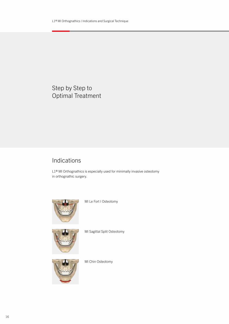
L1® MI Orthognathics is especially used for minimally invasive osteotomy in orthognathic surgery.
Step by Step to Optimal Treatment
Indications
MI Le Fort I Osteotomy
MI Sagittal Split Osteotomy
MI Chin Osteotomy
17
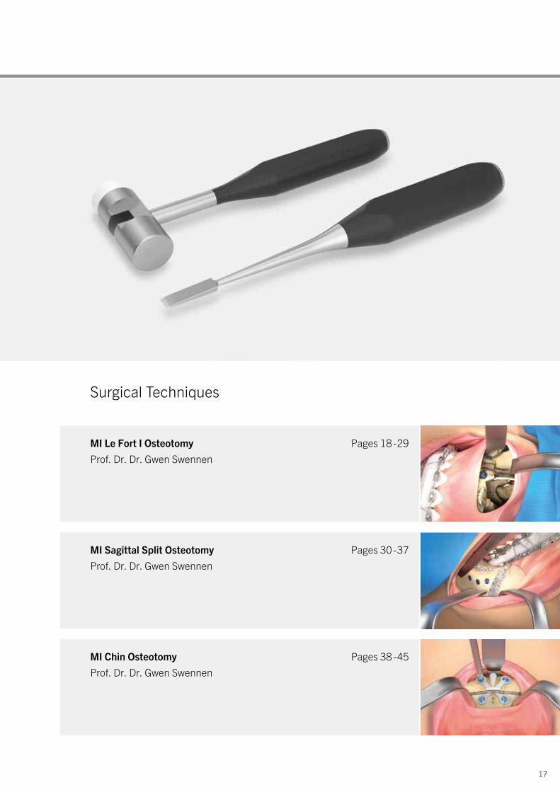
Surgical Techniques
MI Le Fort I Osteotomy Pages 18 - 29Prof. Dr. Dr. Gwen Swennen
MI Sagittal Split Osteotomy Pages 30 - 37Prof. Dr. Dr. Gwen Swennen
MI Chin Osteotomy Pages 38 - 45 Prof. Dr. Dr. Gwen Swennen
18
L1® MI Orthognathics | MI Le Fort I Osteotomy: Surgical Technique
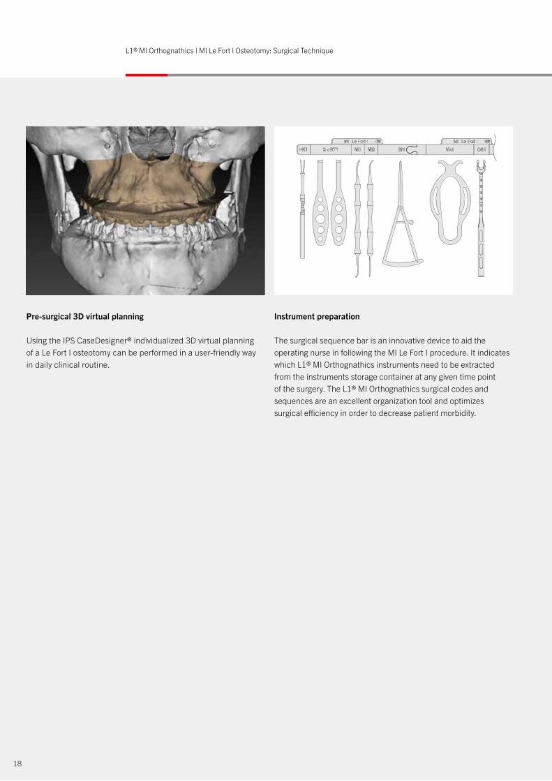
Pre-surgical 3D virtual planning
Using the IPS CaseDesigner® individualized 3D virtual planning of a Le Fort I osteotomy can be performed in a user-friendly way in daily clinical routine.
Instrument preparation
The surgical sequence bar is an innovative device to aid the operating nurse in following the MI Le Fort I procedure. It indicates which L1® MI Orthognathics instruments need to be extracted from the instruments storage container at any given time point of the surgery. The L1® MI Orthognathics surgical codes and sequences are an excellent organization tool and optimizes surgical efficiency in order to decrease patient morbidity.

19
Patient positioning
To perform a MI Le Fort I osteotomy, the patient is positioned in a supine position on the operating table. Nasal intubation is performed with the tube positioned in the midline closely adapted to the forehead midline contour of the patient.
The operating surgeon is positioned in front of the head of the patient while two surgical assistants are positioned laterally at both sides of the head of the patient.
In the ideal setting, the anaesthesiologist is positioned at the left side of the patient’s feet while the surgical nurse is positioned at the right side of the patient’s thorax.
Surgeon’s view
The following MI Le Fort I osteotomy is shown from the surgeon’s perspective.

1. Soft tissue approach to the Le Fort I
The MI approach towards a Le Fort I osteotomy starts by gently placing a soft tissue double hook (HK1) by the operating surgeon in the midline of the mucosa of the upper lip close to its border. Consecutively, two small curved soft tissue retractors (2x RT1) are placed by the two surgical assistants to retract the soft tissues of the upper lip.
A mucosal incision is made from lateral to lateral incisor using a 15 scalpel or a Colorado knife followed by incision of the deep layers through the periosteum at the Le Fort I level allowing a good muscle bulk for paranasal cross-suturing of the nasolabial muscles.
2. Subperiosteal dissection of the medial pillar of the maxilla
Strictly subperiosteal degloving is now performed using the large part of the double-sided sharp raspatorium (MI1) along the right lateral nasal wall. Consecutively, the inner part of the lateral nasal wall is degloved initially using the small part of the double-sided sharp raspatorium (MI1) and then with its larger part.
Same procedure at the left side.
2x RT1 retractor
RT1 retractor
HK1skin hooklet
MI1raspatory
20
L1® MI Orthognathics | MI Le Fort I Osteotomy: Surgical Technique
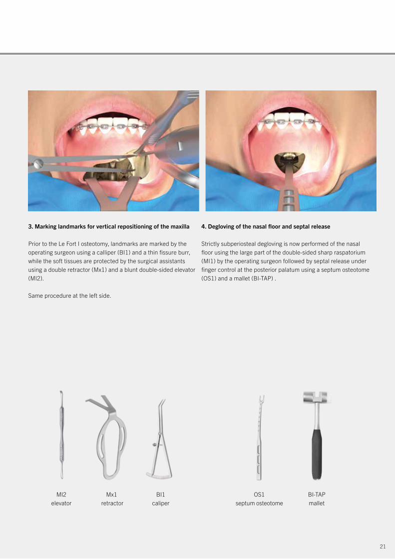
3. Marking landmarks for vertical repositioning of the maxilla
Prior to the Le Fort I osteotomy, landmarks are marked by the operating surgeon using a calliper (BI1) and a thin fissure burr, while the soft tissues are protected by the surgical assistants using a double retractor (Mx1) and a blunt double-sided elevator (MI2).
Same procedure at the left side.
4. Degloving of the nasal floor and septal release
Strictly subperiosteal degloving is now performed of the nasal floor using the large part of the double-sided sharp raspatorium (MI1) by the operating surgeon followed by septal release under finger control at the posterior palatum using a septum osteotome (OS1) and a mallet (BI-TAP) .
MI2elevator
Mx1 retractor
BI1caliper
OS1septum osteotome
BI-TAPmallet
21
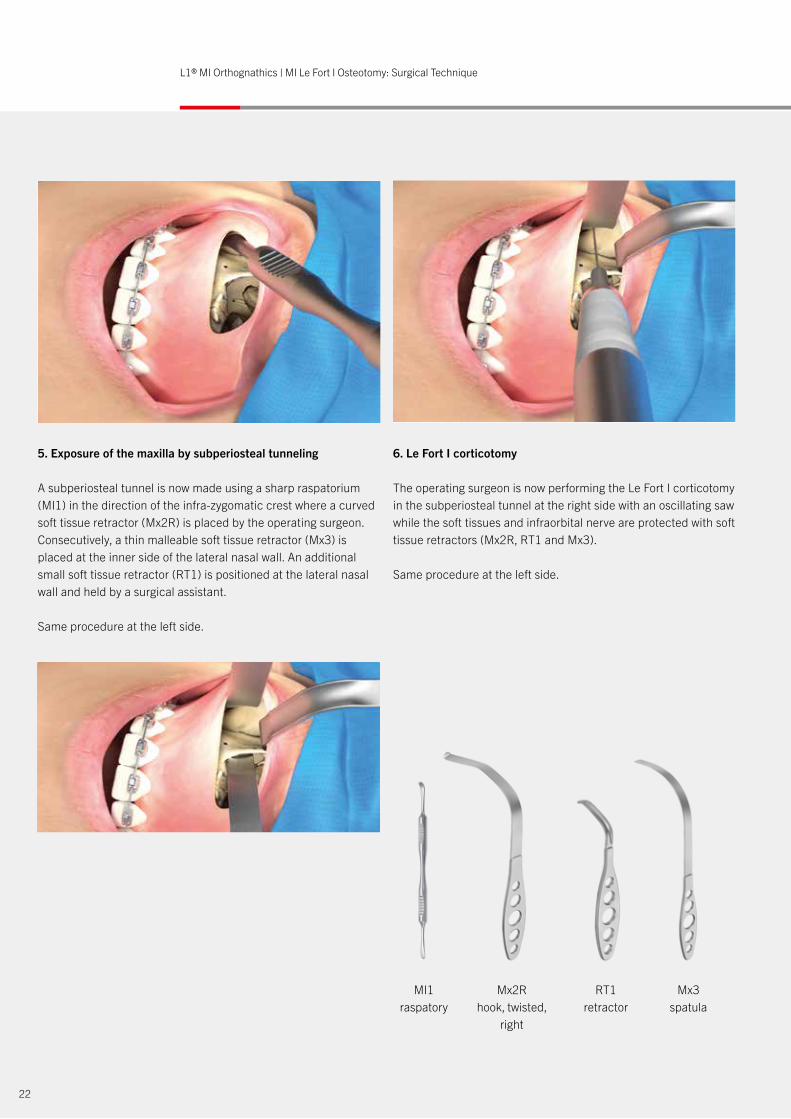
5. Exposure of the maxilla by subperiosteal tunneling
A subperiosteal tunnel is now made using a sharp raspatorium (MI1) in the direction of the infra-zygomatic crest where a curved soft tissue retractor (Mx2R) is placed by the operating surgeon. Consecutively, a thin malleable soft tissue retractor (Mx3) is placed at the inner side of the lateral nasal wall. An additional small soft tissue retractor (RT1) is positioned at the lateral nasal wall and held by a surgical assistant.
Same procedure at the left side.
6. Le Fort I corticotomy
The operating surgeon is now performing the Le Fort I corticotomy in the subperiosteal tunnel at the right side with an oscillating saw while the soft tissues and infraorbital nerve are protected with soft tissue retractors (Mx2R, RT1 and Mx3).
Same procedure at the left side.
MI1raspatory
Mx2Rhook, twisted,
right
RT1 retractor
Mx3spatula
22
L1® MI Orthognathics | MI Le Fort I Osteotomy: Surgical Technique
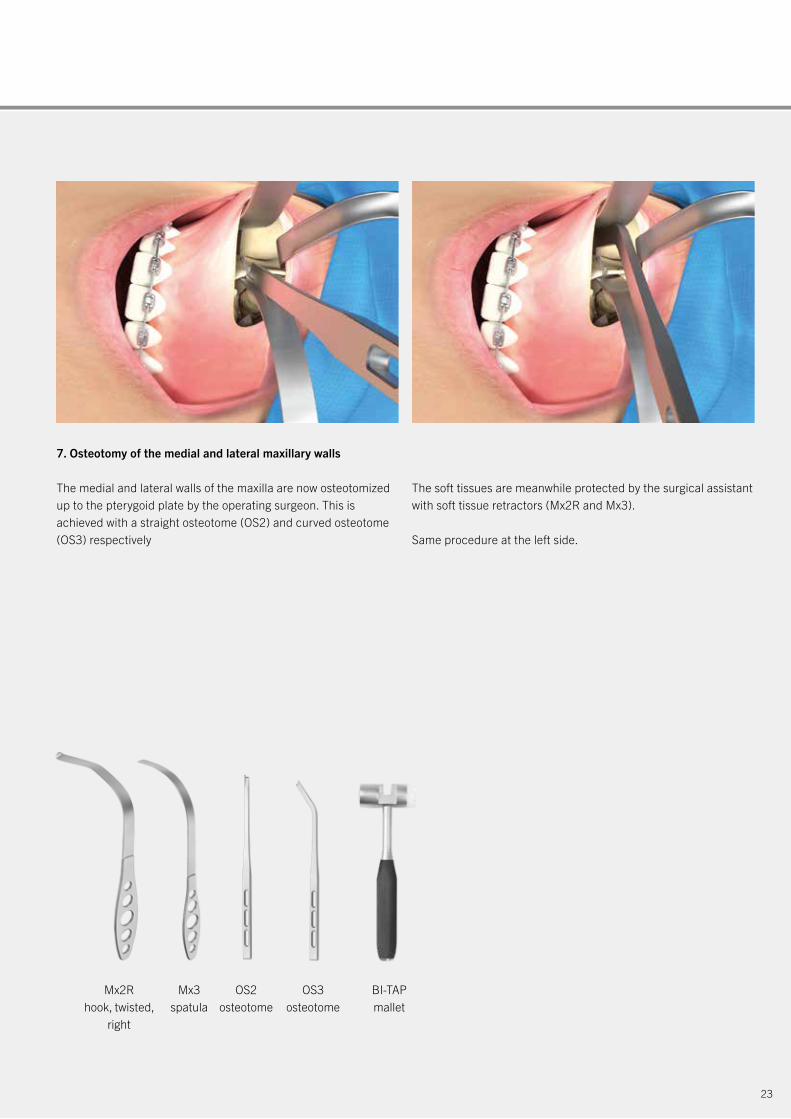
7. Osteotomy of the medial and lateral maxillary walls
The medial and lateral walls of the maxilla are now osteotomized up to the pterygoid plate by the operating surgeon. This is achieved with a straight osteotome (OS2) and curved osteotome (OS3) respectively
The soft tissues are meanwhile protected by the surgical assistant with soft tissue retractors (Mx2R and Mx3).
Same procedure at the left side.
Mx2Rhook, twisted,
right
Mx3spatula
OS2osteotome
OS3osteotome
BI-TAPmallet
23
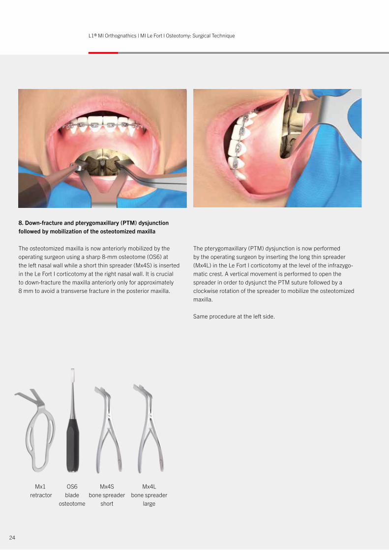
8. Down-fracture and pterygomaxillary (PTM) dysjunction followed by mobilization of the osteotomized maxilla
The osteotomized maxilla is now anteriorly mobilized by the operating surgeon using a sharp 8-mm osteotome (OS6) at the left nasal wall while a short thin spreader (Mx4S) is inserted in the Le Fort I corticotomy at the right nasal wall. It is crucial to down-fracture the maxilla anteriorly only for approximately 8 mm to avoid a transverse fracture in the posterior maxilla.
The pterygomaxillary (PTM) dysjunction is now performed by the operating surgeon by inserting the long thin spreader (Mx4L) in the Le Fort I corticotomy at the level of the infrazygo-matic crest. A vertical movement is performed to open the spreader in order to dysjunct the PTM suture followed by a clockwise rotation of the spreader to mobilize the osteotomized maxilla.
Same procedure at the left side.
Mx1 retractor
OS6blade
osteotome
Mx4Sbone spreader
short
Mx4Lbone spreader
large
24
L1® MI Orthognathics | MI Le Fort I Osteotomy: Surgical Technique
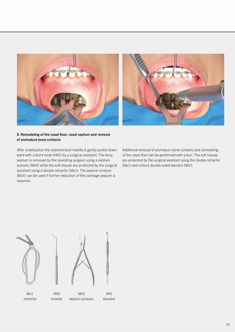
9. Remodeling of the nasal floor, nasal septum and removal of premature bone contacts
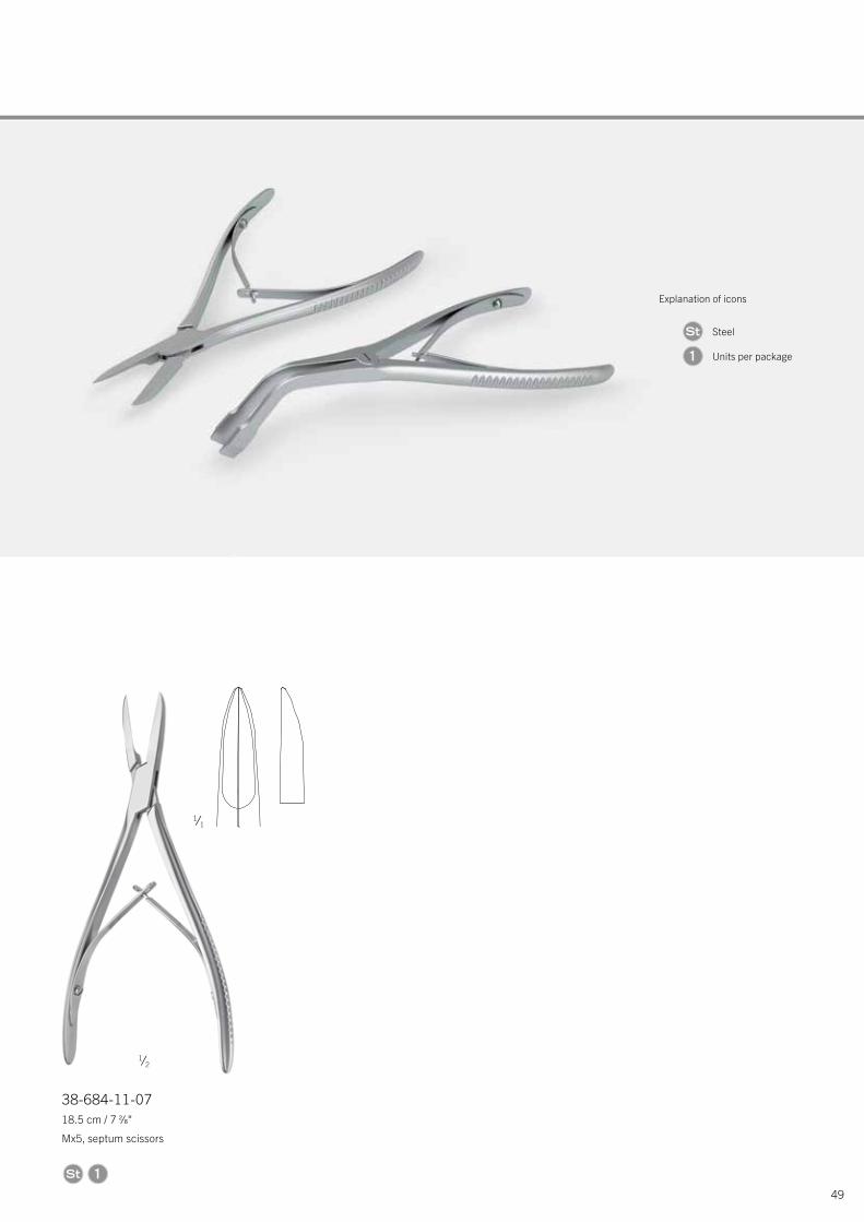
After mobilization the osteotomized maxilla is gently pulled down-ward with a blunt hook (HK2) by a surgical assistant. The bony septum is removed by the operating surgeon using a septum scissors (Mx5) while the soft tissues are protected by the surgical assistant using a double retractor (Mx1). The septum scissors (Mx5) can be used if further reduction of the cartilage septum is required.
Additional removal of premature bone contacts and remodeling of the nasal floor can be performed with a burr. The soft tissues are protected by the surgical assistant using the double retractor (Mx1) and a blunt double-sided elevator (MI2).
Mx1 retractor
HK2hooklet
Mx5septum scissors
MI2elevator
25
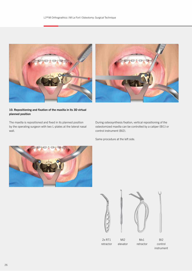
10. Repositioning and fixation of the maxilla in its 3D virtual planned position
The maxilla is repositioned and fixed in its planned position by the operating surgeon with two L-plates at the lateral nasal wall.
During osteosynthesis fixation, vertical repositioning of the osteotomized maxilla can be controlled by a caliper (BI1) or control instrument (BI2).
Same procedure at the left side.
2x RT1 retractor
MI2elevator
Mx1 retractor
BI2control
instrument
26
L1® MI Orthognathics | MI Le Fort I Osteotomy: Surgical Technique
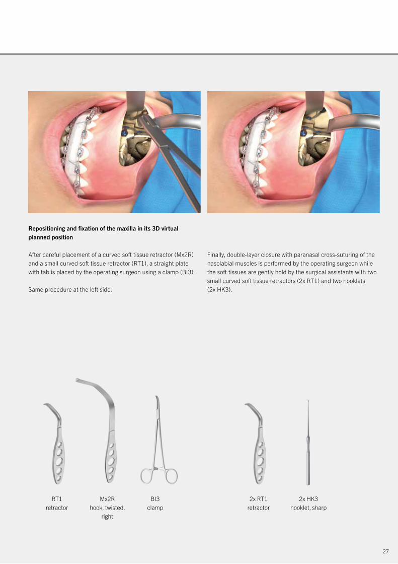
Repositioning and fixation of the maxilla in its 3D virtual planned position
After careful placement of a curved soft tissue retractor (Mx2R) and a small curved soft tissue retractor (RT1), a straight plate with tab is placed by the operating surgeon using a clamp (BI3).
Same procedure at the left side.
Finally, double-layer closure with paranasal cross-suturing of the nasolabial muscles is performed by the operating surgeon while the soft tissues are gently hold by the surgical assistants with two small curved soft tissue retractors (2x RT1) and two hooklets (2x HK3).
2x RT1 retractor
RT1 retractor
Mx2Rhook, twisted,
right
BI3clamp
2x HK3hooklet, sharp
27
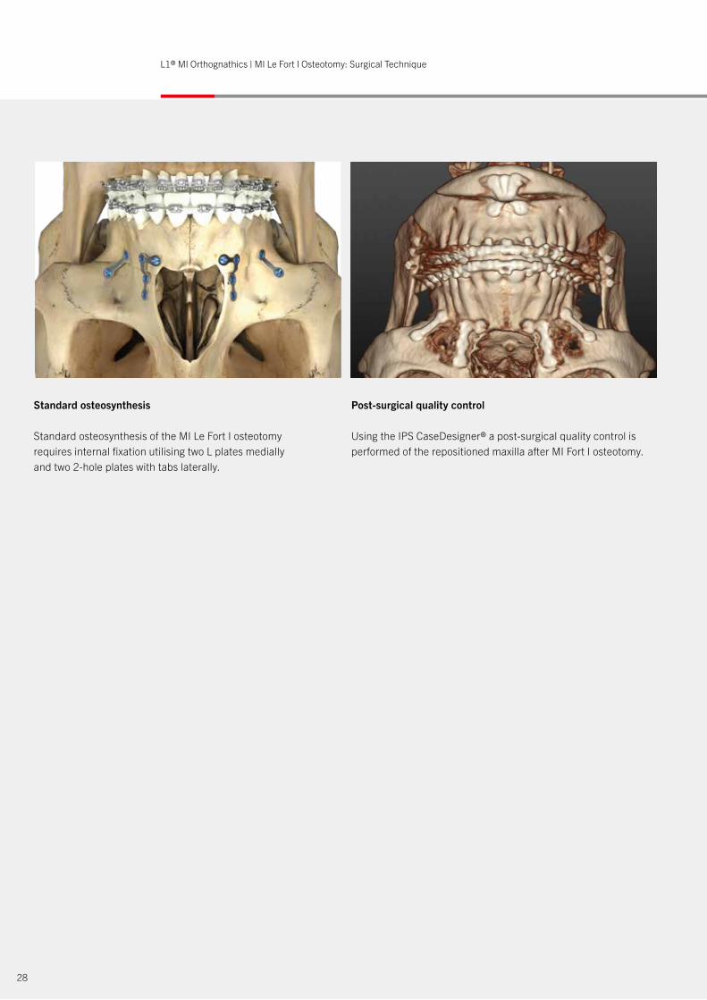
Post-surgical quality control
Using the IPS CaseDesigner® a post-surgical quality control is performed of the repositioned maxilla after MI Fort I osteotomy.
Standard osteosynthesis
Standard osteosynthesis of the MI Le Fort I osteotomy requires internal fixation utilising two L plates medially and two 2-hole plates with tabs laterally.
28
L1® MI Orthognathics | MI Le Fort I Osteotomy: Surgical Technique
Using the IPS CaseDesigner® a post-surgical quality control is performed of the repositioned maxilla after MI Fort I osteotomy.
29
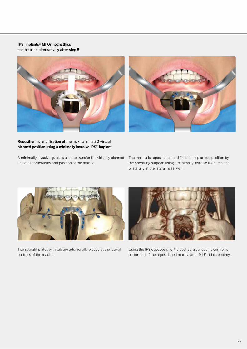
Repositioning and fixation of the maxilla in its 3D virtual planned position using a minimally invasive IPS® implant
A minimally invasive guide is used to transfer the virtually planned Le Fort I corticotomy and position of the maxilla.
IPS Implants® MI Orthognathicscan be used alternatively after step 5
The maxilla is repositioned and fixed in its planned position by the operating surgeon using a minimally invasive IPS® implant bilaterally at the lateral nasal wall.
Two straight plates with tab are additionally placed at the lateral buttress of the maxilla.
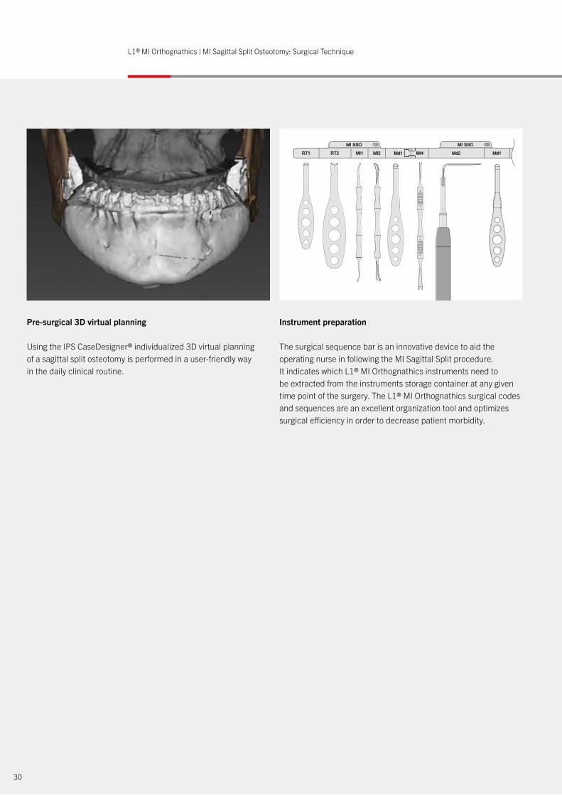
Pre-surgical 3D virtual planning
Using the IPS CaseDesigner® individualized 3D virtual planning of a sagittal split osteotomy is performed in a user-friendly way in the daily clinical routine.
Instrument preparation
The surgical sequence bar is an innovative device to aid the operating nurse in following the MI Sagittal Split procedure. It indicates which L1® MI Orthognathics instruments need to be extracted from the instruments storage container at any given time point of the surgery. The L1® MI Orthognathics surgical codes and sequences are an excellent organization tool and optimizes surgical efficiency in order to decrease patient morbidity.
30
L1® MI Orthognathics | MI Sagittal Split Osteotomy: Surgical Technique
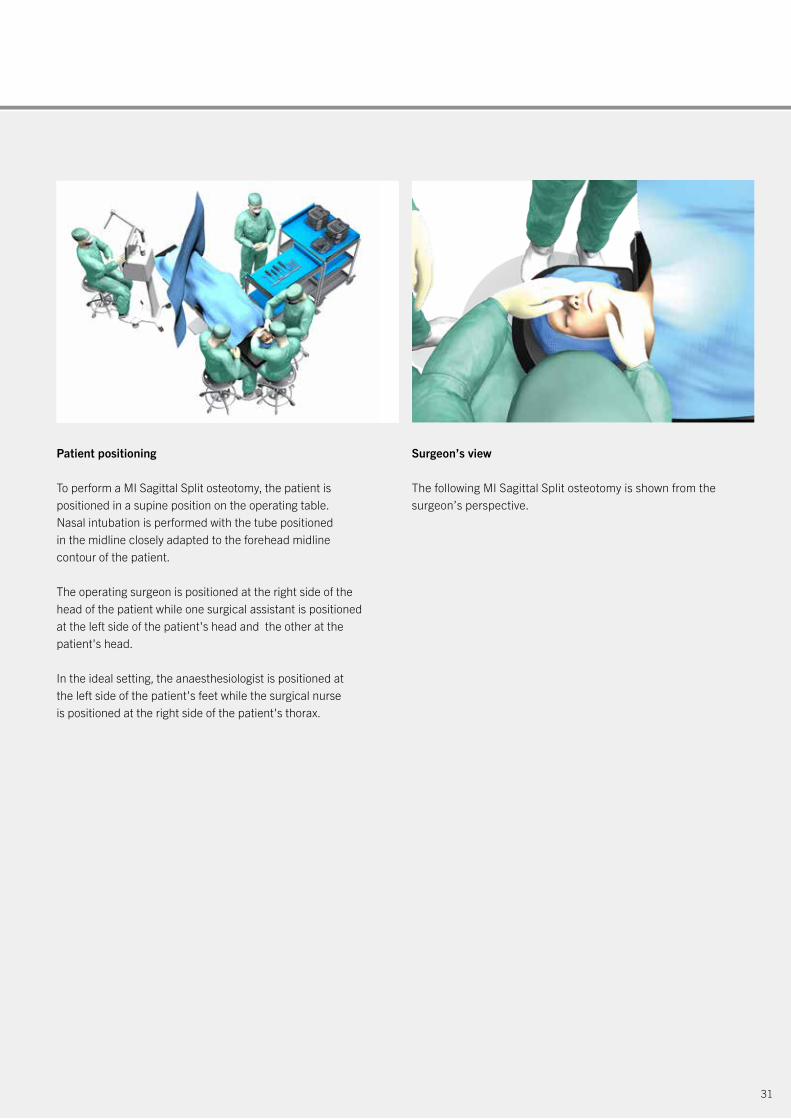
Patient positioning
To perform a MI Sagittal Split osteotomy, the patient is positioned in a supine position on the operating table. Nasal intubation is performed with the tube positioned in the midline closely adapted to the forehead midline contour of the patient.
The operating surgeon is positioned at the right side of the head of the patient while one surgical assistant is positioned at the left side of the patient's head and the other at the patient's head.
In the ideal setting, the anaesthesiologist is positioned at the left side of the patient's feet while the surgical nurse is positioned at the right side of the patient's thorax.
31
Surgeon’s view
The following MI Sagittal Split osteotomy is shown from the surgeon’s perspective.
HK1 RT1 RT1 MI1 Ch1 MI3 OS5 BI-TAP OS6 BI3L1® MI Orthognathics – MI Chin Surgical Codes and Sequence
32
L1® MI Orthognathics | MI Sagittal Split Osteotomy: Surgical Technique
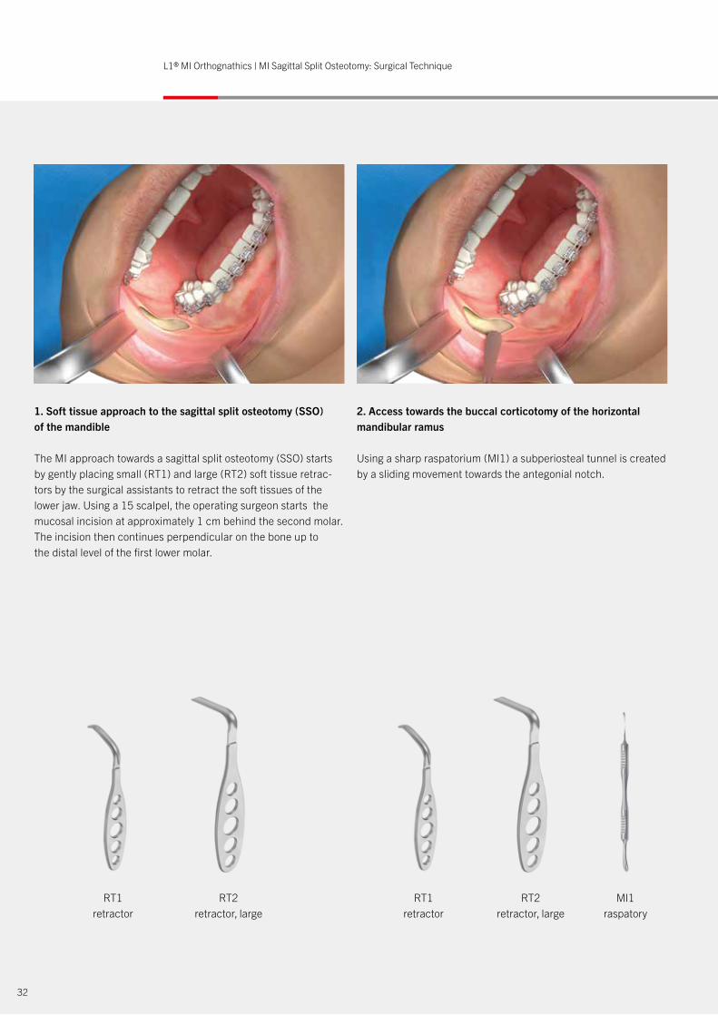
1. Soft tissue approach to the sagittal split osteotomy (SSO) of the mandible
The MI approach towards a sagittal split osteotomy (SSO) starts by gently placing small (RT1) and large (RT2) soft tissue retrac-tors by the surgical assistants to retract the soft tissues of the lower jaw. Using a 15 scalpel, the operating surgeon starts the mucosal incision at approximately 1 cm behind the second molar. The incision then continues perpendicular on the bone up to the distal level of the first lower molar.
2. Access towards the buccal corticotomy of the horizontal mandibular ramus
Using a sharp raspatorium (MI1) a subperiosteal tunnel is created by a sliding movement towards the antegonial notch.
RT1 retractor
RT1 retractor
RT2 retractor, large
RT2 retractor, large
MI1raspatory
xxxyv xxx
HK1 RT1 RT1 MI1 Ch1 MI3 OS5 BI-TAP OS6 BI3L1® MI Orthognathics – MI Chin Surgical Codes and Sequence
33
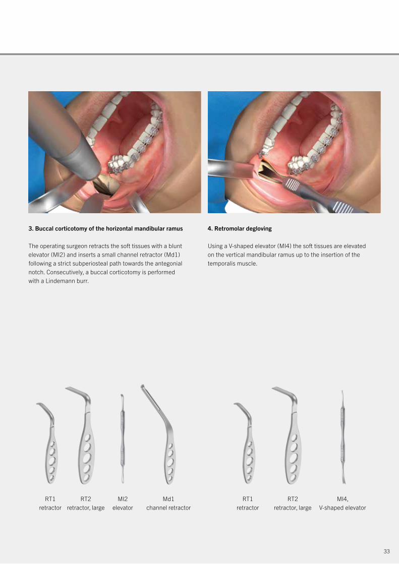
3. Buccal corticotomy of the horizontal mandibular ramus
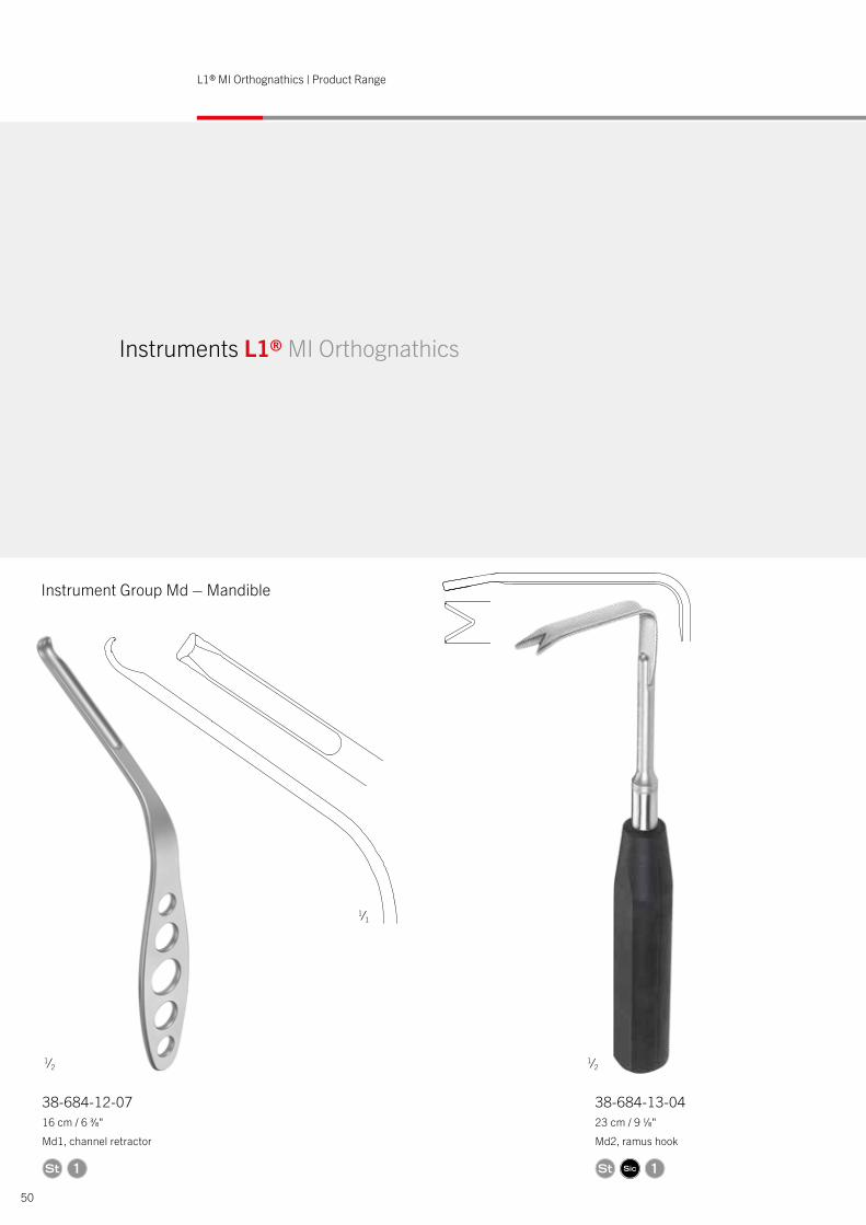
The operating surgeon retracts the soft tissues with a blunt elevator (MI2) and inserts a small channel retractor (Md1) following a strict subperiosteal path towards the antegonial notch. Consecutively, a buccal corticotomy is performed with a Lindemann burr.
4. Retromolar degloving
Using a V-shaped elevator (MI4) the soft tissues are elevated on the vertical mandibular ramus up to the insertion of the temporalis muscle.
RT2 retractor, large
RT2 retractor, large
Md1 channel retractor
MI2elevator
MI4, V-shaped elevator
RT1 retractor
RT1 retractor
34
L1® MI Orthognathics | MI Sagittal Split Osteotomy: Surgical Technique
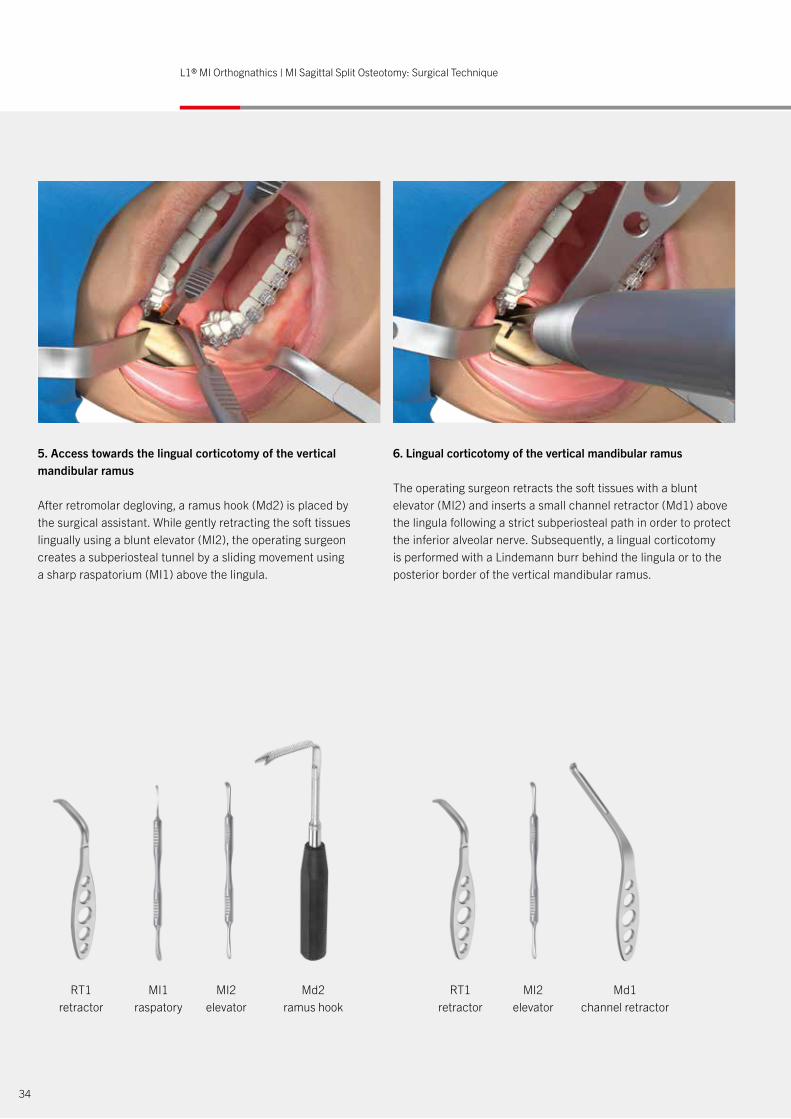
5. Access towards the lingual corticotomy of the vertical mandibular ramus
After retromolar degloving, a ramus hook (Md2) is placed by the surgical assistant. While gently retracting the soft tissues lingually using a blunt elevator (MI2), the operating surgeon creates a subperiosteal tunnel by a sliding movement using a sharp raspatorium (MI1) above the lingula.
6. Lingual corticotomy of the vertical mandibular ramus
The operating surgeon retracts the soft tissues with a blunt elevator (MI2) and inserts a small channel retractor (Md1) above the lingula following a strict subperiosteal path in order to protect the inferior alveolar nerve. Subsequently, a lingual corticotomy is performed with a Lindemann burr behind the lingula or to the posterior border of the vertical mandibular ramus.
MI1raspatory
MI2elevator
MI2elevator
Md2ramus hook
Md1 channel retractor
RT1 retractor
RT1 retractor
35
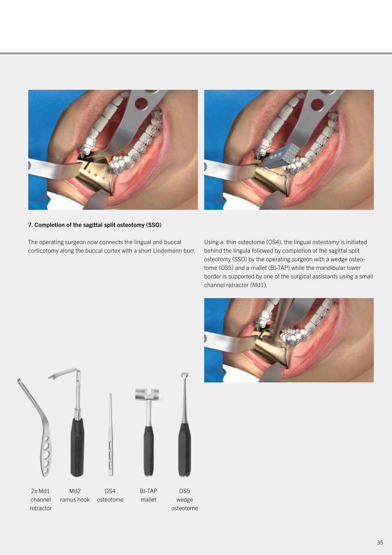
7. Completion of the sagittal split osteotomy (SSO)
The operating surgeon now connects the lingual and buccal corticotomy along the buccal cortex with a short Lindemann burr.
Using a thin osteotome (OS4), the lingual osteotomy is initiated behind the lingula followed by completion of the sagittal split osteotomy (SSO) by the operating surgeon with a wedge osteo-tome (OS5) and a mallet (BI-TAP) while the mandibular lower border is supported by one of the surgical assistants using a small channel retractor (Md1).
Md2ramus hook
2x Md1 channel retractor
OS4osteotome
OS5wedge
osteotome
BI-TAPmallet

36
L1® MI Orthognathics | MI Sagittal Split Osteotomy: Surgical Technique
8. Mobilization of the mandibular segments after sagittal split osteotomy
The proximal mandibular segment is now further released and mobilized by the operating surgeon using a wedge-osteotome (OS5) and an 8 mm sharp osteotome (OS6).
9. Tri-vector seating of the mandibular proximal segment
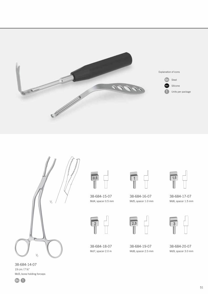
The proximal segment is now seated in centric relation by the operating surgeon using a V-shaped elevator (MI4) and a bone holding forceps (Md3). To avoid torque on the condyle, a MI spacer (Md4-9) can be placed in between the proximal and distal mandibular fragments.
Md2ramus hook
OS5wedge
osteotome
Md1 channelretractor
OS6 blade
osteotome
MI4, V-shaped elevator
BI3clamp
Md4-9spacer
Md3bone holding
forceps
37
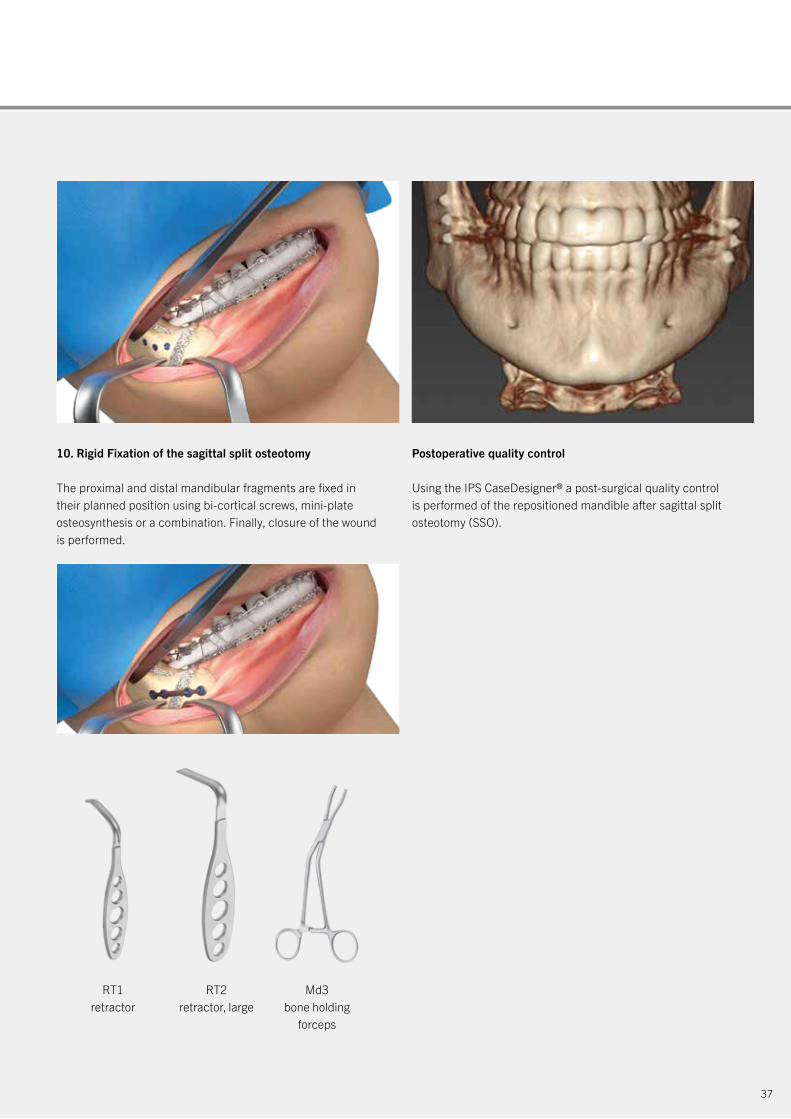
10. Rigid Fixation of the sagittal split osteotomy
The proximal and distal mandibular fragments are fixed in their planned position using bi-cortical screws, mini-plate osteosynthesis or a combination. Finally, closure of the wound is performed.
Postoperative quality control
Using the IPS CaseDesigner® a post-surgical quality control is performed of the repositioned mandible after sagittal split osteotomy (SSO).
Md3bone holding
forceps
RT1 retractor
RT2 retractor, large
38
L1® MI Orthognathics | MI Chin Osteotomy: Surgical Technique
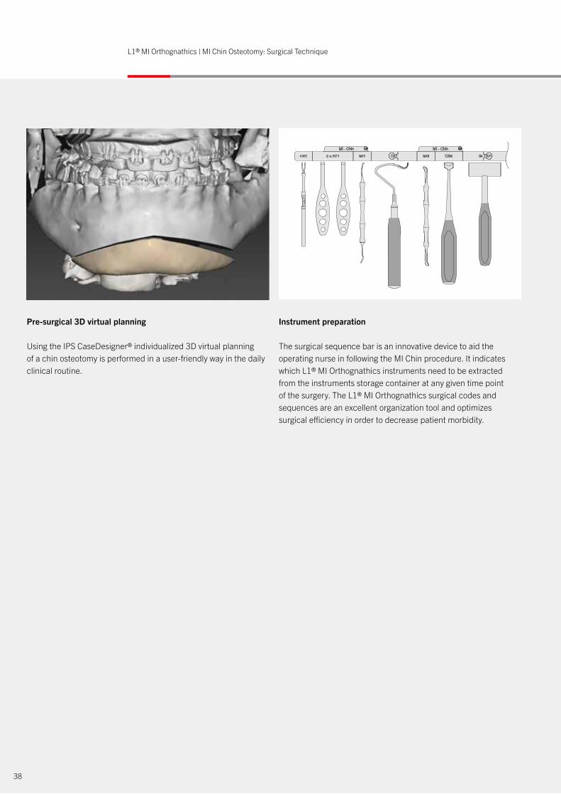
Pre-surgical 3D virtual planning
Using the IPS CaseDesigner® individualized 3D virtual planning of a chin osteotomy is performed in a user-friendly way in the daily clinical routine.
Instrument preparation
The surgical sequence bar is an innovative device to aid the operating nurse in following the MI Chin procedure. It indicates which L1® MI Orthognathics instruments need to be extracted from the instruments storage container at any given time point of the surgery. The L1® MI Orthognathics surgical codes and sequences are an excellent organization tool and optimizes surgical efficiency in order to decrease patient morbidity.
39
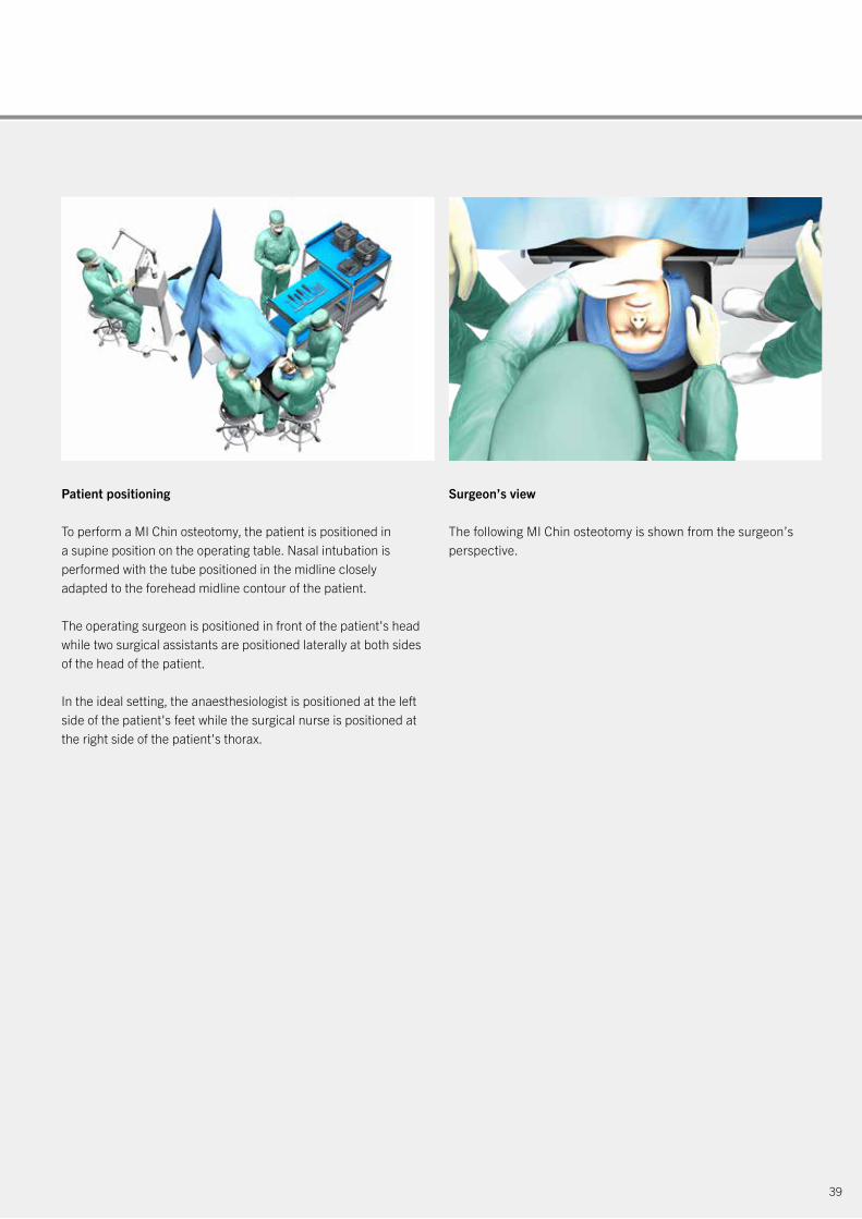
Patient positioning
To perform a MI Chin osteotomy, the patient is positioned in a supine position on the operating table. Nasal intubation is performed with the tube positioned in the midline closely adapted to the forehead midline contour of the patient.
The operating surgeon is positioned in front of the patient's head while two surgical assistants are positioned laterally at both sides of the head of the patient.
In the ideal setting, the anaesthesiologist is positioned at the left side of the patient's feet while the surgical nurse is positioned at the right side of the patient's thorax.
Surgeon’s view
The following MI Chin osteotomy is shown from the surgeon’s perspective.
HK1 RT1 RT1 MI1 Ch1 MI3 OS5 BI-TAP OS6 BI3L1® MI Orthognathics – MI Chin Surgical Codes and Sequence
40
L1® MI Orthognathics | MI Chin Osteotomy: Surgical Technique
2x RT1 retractor
HK1skin hooklet
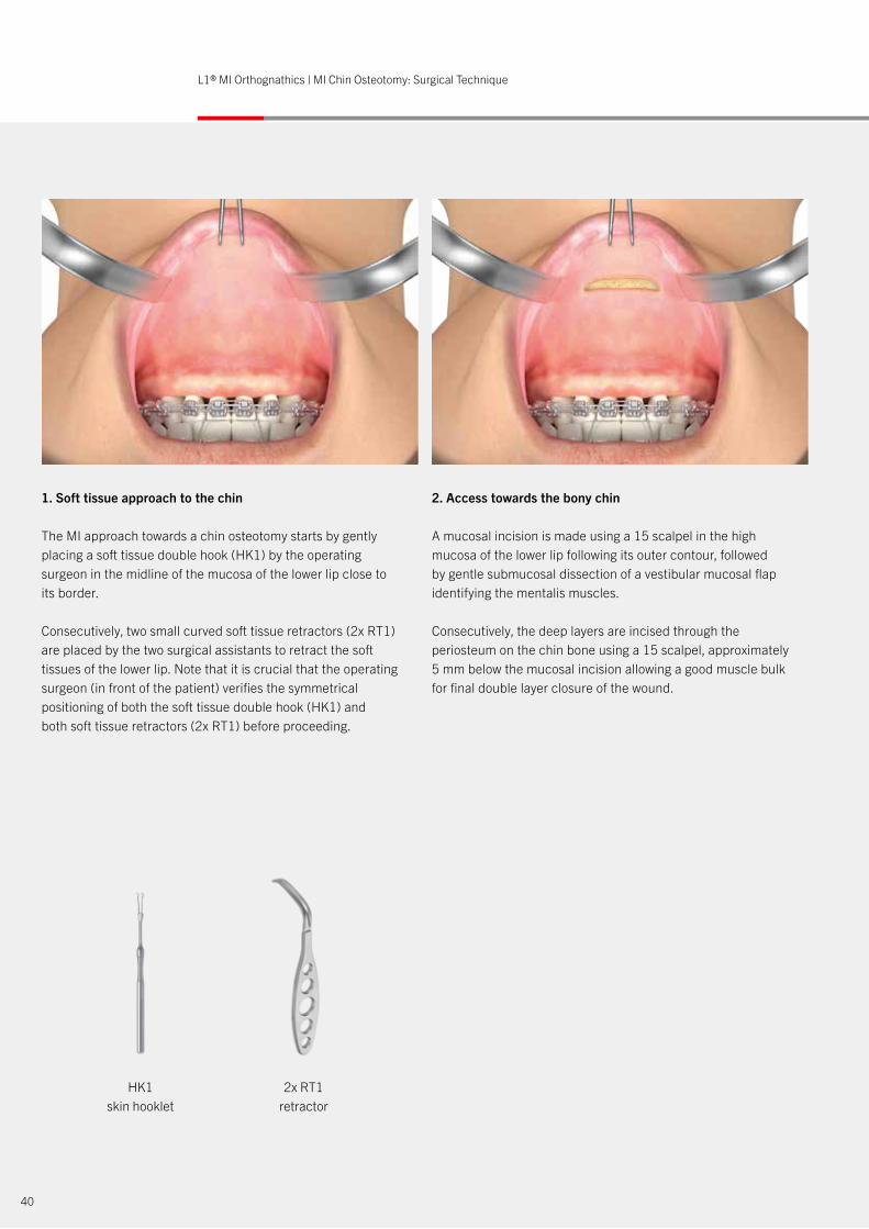
1. Soft tissue approach to the chin
The MI approach towards a chin osteotomy starts by gently placing a soft tissue double hook (HK1) by the operating surgeon in the midline of the mucosa of the lower lip close to its border.
Consecutively, two small curved soft tissue retractors (2x RT1) are placed by the two surgical assistants to retract the soft tissues of the lower lip. Note that it is crucial that the operating surgeon (in front of the patient) verifies the symmetrical positioning of both the soft tissue double hook (HK1) and both soft tissue retractors (2x RT1) before proceeding.
2. Access towards the bony chin
A mucosal incision is made using a 15 scalpel in the high mucosa of the lower lip following its outer contour, followed by gentle submucosal dissection of a vestibular mucosal flap identifying the mentalis muscles.
Consecutively, the deep layers are incised through the periosteum on the chin bone using a 15 scalpel, approximately 5 mm below the mucosal incision allowing a good muscle bulk for final double layer closure of the wound.
xxxyv xxx
HK1 RT1 RT1 MI1 Ch1 MI3 OS5 BI-TAP OS6 BI3L1® MI Orthognathics – MI Chin Surgical Codes and Sequence
41
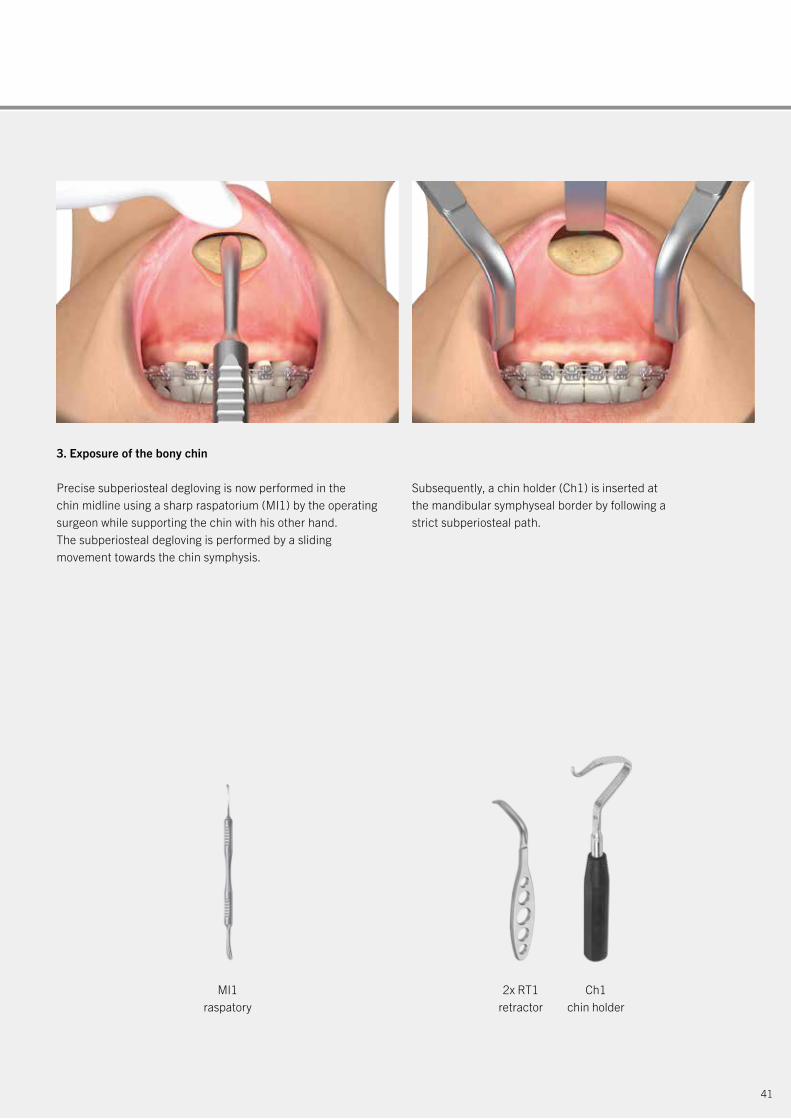
3. Exposure of the bony chin
Precise subperiosteal degloving is now performed in the chin midline using a sharp raspatorium (MI1) by the operating surgeon while supporting the chin with his other hand. The subperiosteal degloving is performed by a sliding movement towards the chin symphysis.
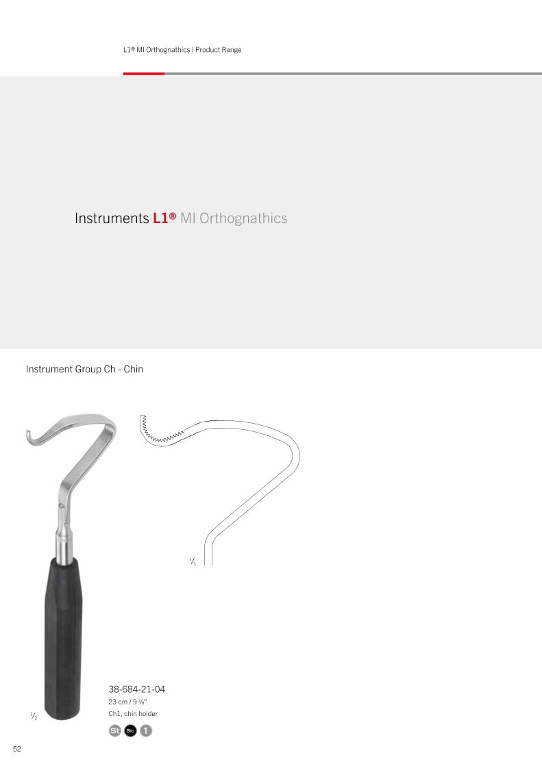
Subsequently, a chin holder (Ch1) is inserted at the mandibular symphyseal border by following a strict subperiosteal path.
2x RT1 retractor
MI1raspatory
Ch1chin holder
HK1 RT1 RT1 MI1 Ch1 MI3 OS5 BI-TAP OS6 BI3L1® MI Orthognathics – MI Chin Surgical Codes and Sequence
HK1 RT1 RT1 MI1 Ch1 MI3 OS5 BI-TAP OS6 BI3L1® MI Orthognathics – MI Chin Surgical Codes and Sequence
42
L1® MI Orthognathics | MI Chin Osteotomy: Surgical Technique
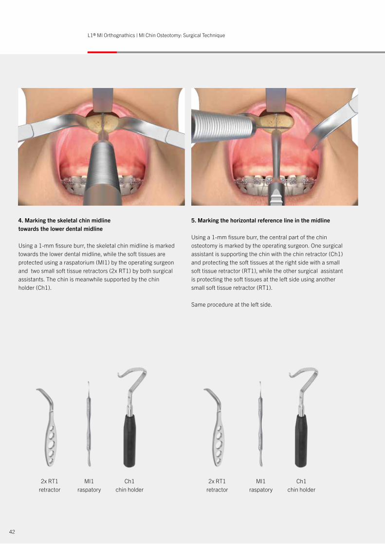
4. Marking the skeletal chin midline towards the lower dental midline
Using a 1-mm fissure burr, the skeletal chin midline is marked towards the lower dental midline, while the soft tissues are protected using a raspatorium (MI1) by the operating surgeon and two small soft tissue retractors (2x RT1) by both surgical assistants. The chin is meanwhile supported by the chin holder (Ch1).
5. Marking the horizontal reference line in the midline
Using a 1-mm fissure burr, the central part of the chin osteotomy is marked by the operating surgeon. One surgical assistant is supporting the chin with the chin retractor (Ch1) and protecting the soft tissues at the right side with a small soft tissue retractor (RT1), while the other surgical assistant is protecting the soft tissues at the left side using another small soft tissue retractor (RT1).
Same procedure at the left side.
2x RT1 retractor
2x RT1 retractor
Ch1 chin holder
Ch1 chin holder
MI1raspatory
MI1raspatory
xxxyv xxx
xxxyv xxx
HK1 RT1 RT1 MI1 Ch1 MI3 OS5 BI-TAP OS6 BI3L1® MI Orthognathics – MI Chin Surgical Codes and Sequence
43
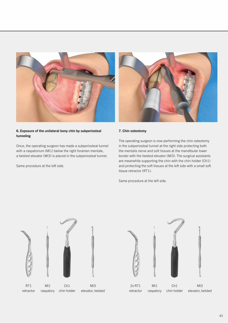
6. Exposure of the unilateral bony chin by subperiosteal tunneling
Once, the operating surgeon has made a subperiosteal tunnel with a raspatorium (MI1) below the right foramen mentale, a twisted elevator (MI3) is placed in the subperiosteal tunnel.
Same procedure at the left side.
7. Chin osteotomy
The operating surgeon is now performing the chin osteotomy in the subperiosteal tunnel at the right side protecting both the mentalis nerve and soft tissues at the mandibular lower border with the twisted elevator (MI3). The surgical assistants are meanwhile supporting the chin with the chin holder (Ch1) and protecting the soft tissues at the left side with a small soft tissue retractor (RT1).
Same procedure at the left side.
RT1 retractor
2x RT1 retractor
Ch1 chin holder
Ch1 chin holder
MI1raspatory
MI1raspatory
MI3elevator, twisted
MI3elevator, twisted
HK1 RT1 RT1 MI1 Ch1 MI3 OS5 BI-TAP OS6 BI3L1® MI Orthognathics – MI Chin Surgical Codes and Sequence
44
L1® MI Orthognathics | MI Chin Osteotomy: Surgical Technique
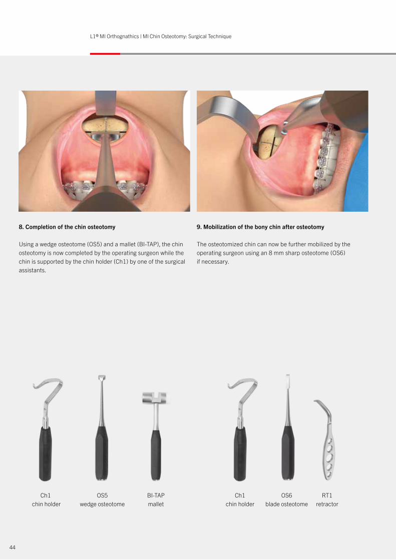
8. Completion of the chin osteotomy
Using a wedge osteotome (OS5) and a mallet (BI-TAP), the chin osteotomy is now completed by the operating surgeon while the chin is supported by the chin holder (Ch1) by one of the surgical assistants.
9. Mobilization of the bony chin after osteotomy
The osteotomized chin can now be further mobilized by the operating surgeon using an 8 mm sharp osteotome (OS6) if necessary.
Ch1 chin holder
Ch1chin holder
OS5wedge osteotome
BI-TAPmallet
OS6 blade osteotome
RT1retractor

xxxyv xxx
HK1 RT1 RT1 MI1 Ch1 MI3 OS5 BI-TAP OS6 BI3L1® MI Orthognathics – MI Chin Surgical Codes and Sequence
45
10. Repositioning and rigid fixation of the chin in its planned position
The chin is repositioned and fixed in its planned position using a pre-bent osteosynthesis plate held by the operating surgeon using a clamp (BI3). Finally, a double-layer closure of the wound is performed.
Post-surgical quality control
Using the IPS CaseDesigner® a post-surgical quality control is performed of the repositioned chin.
2x RT1retractor
Ch1chin holder
BI3clamp
46
L1® MI Orthognathics | Product Range
Instruments L1® MI Orthognathics
Instrument Group Mx - Maxilla
1 1
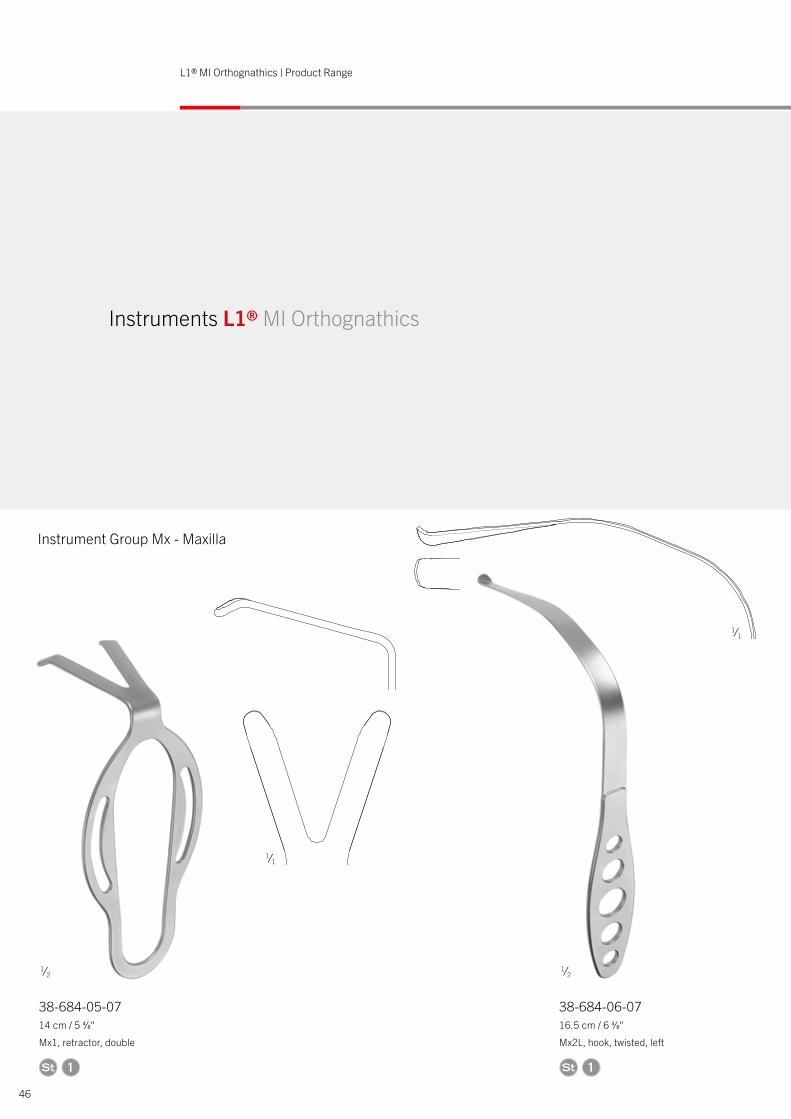
38-684-05-0714 cm / 5 4⁄8"
Mx1, retractor, double
38-684-06-0716.5 cm / 6 4⁄8"
Mx2L, hook, twisted, left
25
166
25
166
1⁄2 1⁄2
1⁄1
1⁄1
47
1 1
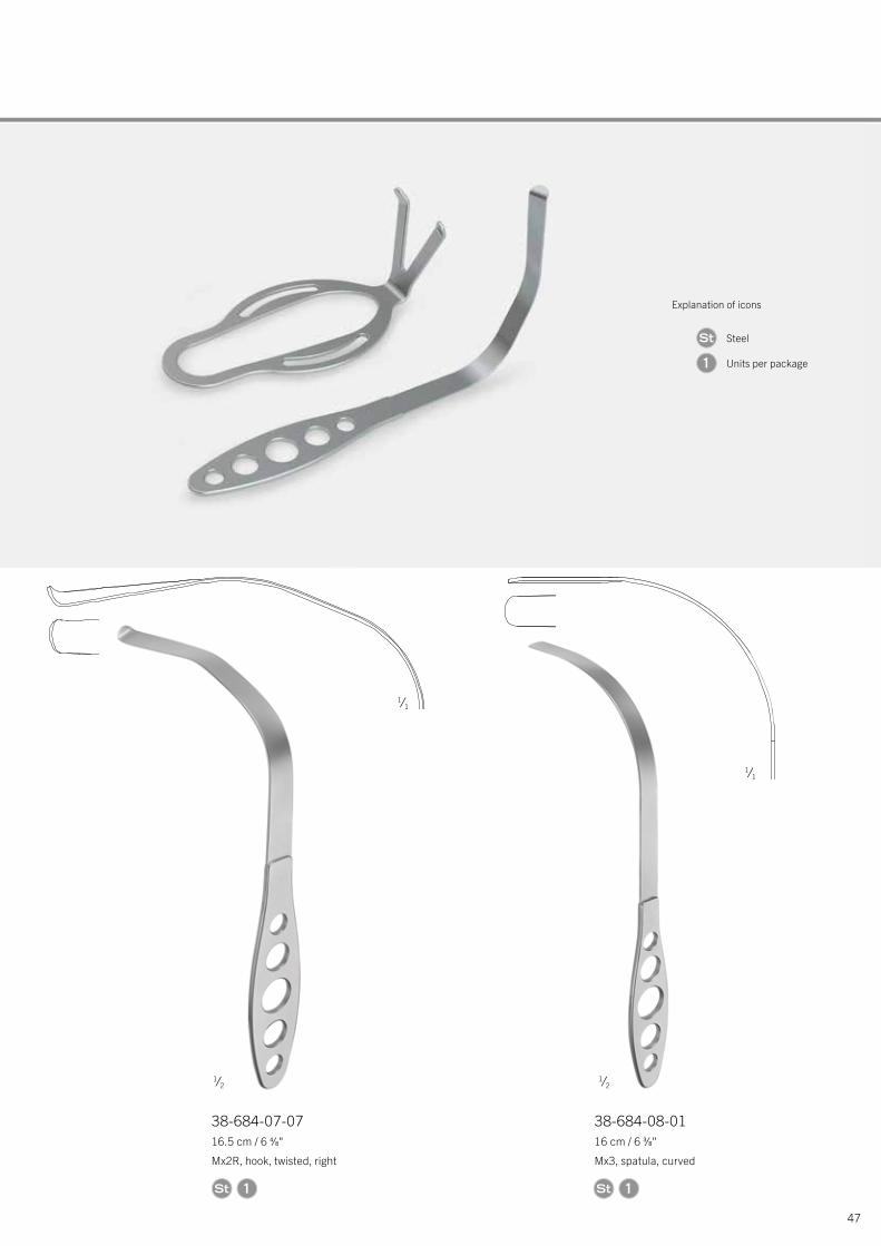
38-684-07-0716.5 cm / 6 4⁄8"
Mx2R, hook, twisted, right
38-684-08-0116 cm / 6 3⁄8"
Mx3, spatula, curved
Explanation of icons
Steel
Units per package1
MATERIAL NUMBERMATERIAL
according to DIN ISO EN 7153-1, current rev.nach DIN EN ISO 7153-1, aktuelle Ausgabe
hardness:Härte:
surface:Ober�äche:
MATERIAL NUMBERMATERIAL
according to DIN ISO EN 7153-1, current rev.nach DIN EN ISO 7153-1, aktuelle Ausgabe
hardness:Härte:
surface:Ober�äche:
63
163
63
163
1⁄2
1⁄1
1⁄1
1⁄2

48
L1® MI Orthognathics | Product Range
Instrument Group Mx - Maxilla
38-684-09-0718 cm / 7 1⁄8"
Mx4S, bone expander short
38-684-10-0718.5 cm / 7 2⁄8"
Mx4L, bone expander long
B
C
D
B
C
D
Instruments L1® MI Orthognathics
1 1
1⁄2 1⁄2
1⁄1 1⁄1
49
38-684-11-0718.5 cm / 7 2⁄8"
Mx5, septum scissors
A
B
C
D
34
Explanation of icons
Steel
Units per package1
1
1⁄2
1⁄1
50
L1® MI Orthognathics | Product Range
160
70
160
70
62,5
38-684-12-0716 cm / 6 3⁄8"
Md1, channel retractor
38-684-13-0423 cm / 9 1⁄8"
Md2, ramus hook
Instrument Group Md – Mandible
Instruments L1® MI Orthognathics
62,5
1 1
1⁄2 1⁄2
1⁄1
51
38-684-14-0719 cm / 7 4⁄8"
Md3, bone holding forceps
38-684-15-07Md4, spacer 0.5 mm
38-684-18-07Md7, spacer 2.0 m
38-684-17-07Md6, spacer 1.5 mm
38-684-20-07Md9, spacer 3.0 mm
38-684-16-07Md5, spacer 1.0 mm
38-684-19-07Md8, spacer 2.5 mm
189
Explanation of icons
Steel
Silicone
Units per package1
1
1⁄2
1⁄1
52
L1® MI Orthognathics | Product Range
Instrument Group Ch - Chin
Instruments L1® MI Orthognathics
38-684-21-0423 cm / 9 1⁄8"
Ch1, chin holder
1
62
1⁄2
1⁄1

38-684-22-0718.5 cm / 7 2⁄8"
MI1, raspatory double-sided
38-684-23-0718.5 cm / 7 2⁄8"
MI2, elevator double-sided
38-684-24-0718.5 cm / 7 2⁄8"
MI3, elevator twisted
38-684-25-0720 cm / 7 7⁄8"
MI4, V-shaped elevator
Instrument Group MI – Minimally Invasive
199
199
199
199
186
186
185,5
185,5
185,5
185,5
185,5
185,5
185,5
185,5
instru
men
t rot
ated
by 45
ĀIn
strum
ent u
m 45
Ā ge
dreh
t
184
instru
men
t rot
ated
by 45
ĀIn
strum
ent u
m 45
Ā ge
dreh
t
184
53
Explanation of icons
Steel
Silicone
Units per package1
1 1 1 1
1⁄2 1⁄2
1⁄2 1⁄2
1⁄1 1⁄1
1⁄1 1⁄1
54
L1® MI Orthognathics | Product Range
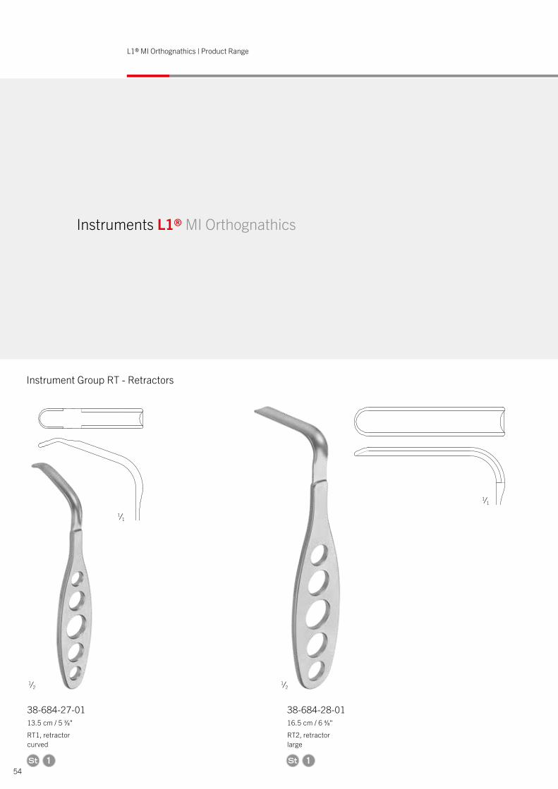
Instrument Group RT - Retractors
A
B
C
D
E
10,8
165
38-684-27-0113.5 cm / 5 3⁄8"
RT1, retractor curved
38-684-28-0116.5 cm / 6 4⁄8"
RT2, retractor large
Instruments L1® MI Orthognathics
1 1
1⁄2 1⁄2
1⁄1
1⁄1
E
The r
eprod
uctio
n, distr
ibutio
n and
utiliz
ation
of th
is doc
umen
t as w
ell as
the co
mmun
icatio
n of it
s con
tents
to oth
ers wi
thout
expres
s auth
orizat
ion is
prohib
ited. O
�end
ers wi
ll be h
eld lia
ble fo
r the p
aymen
t of d
amag
es.All
rights
reser
ved in
the e
vent o
f the g
rant o
f a pa
tent, u
tility
mode
l or d
esign
.
MATERIAL NUMBERMATERIAL BASICSCOPYRIGHT RESERVED
8
135
39
135
M 1:2
55
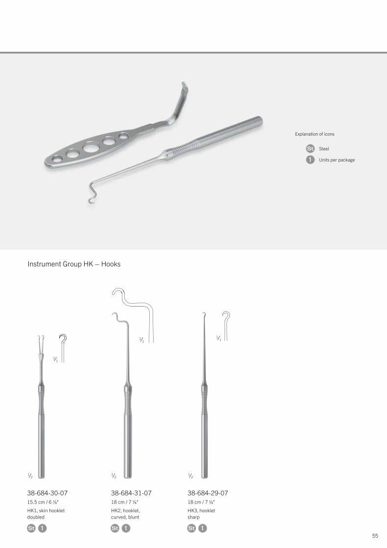
Instrument Group HK – Hooks
38-684-29-0718 cm / 7 1⁄8"
HK3, hooklet sharp
180
22
3,7
180
1
38-684-30-0715.5 cm / 6 1⁄8"
HK1, skin hooklet doubled
180
3,9
Z5:1
1
1⁄2
1⁄1 1⁄1
38-684-31-0718 cm / 7 1⁄8"
HK2, hooklet, curved, blunt
1 2 3 4
A
B
C
D
155
Ă 7
3,7
1
1⁄1
1⁄2 1⁄2
Explanation of icons
Steel
Units per package1
56
L1® MI Orthognathics | Product Range
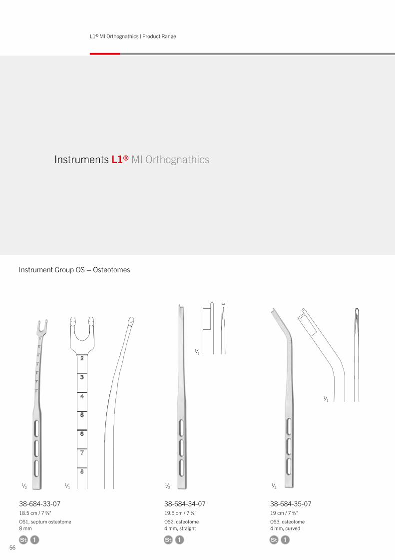
Instrument Group OS – Osteotomes
38-684-33-0718.5 cm / 7 2⁄8"
OS1, septum osteotome 8 mm
38-684-34-0719.5 cm / 7 5⁄8"
OS2, osteotome 4 mm, straight
38-684-35-0719 cm / 7 4⁄8"
OS3, osteotome 4 mm, curved
D
Instruments L1® MI Orthognathics
1 1 1
1⁄2 1⁄2
1⁄2
1⁄1
1⁄1
1⁄1
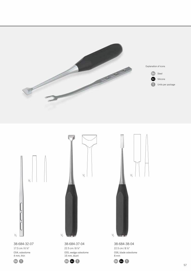
57
38-684-32-0717.5 cm / 6 7⁄8"
OS4, osteotome 4 mm, thin
38-684-37-0422.5 cm / 8 7⁄8"
OS5, wedge osteotome 16 mm, blunt
38-684-38-0422.5 cm / 8 7⁄8"
OS6, blade osteotome 8 mm
225
225
4,59
175,5
1 1 1
1⁄2 1⁄2
1⁄2
1⁄1 1⁄1
1⁄1
Explanation of icons
Steel
Silicone
Units per package1
58
L1® MI Orthognathics | Product Range
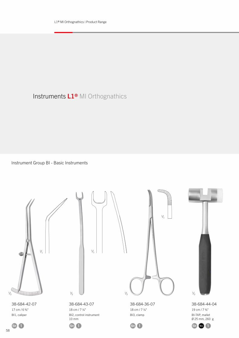
Instrument Group BI - Basic Instruments
38-684-42-0717 cm / 6 6⁄8"
BI1, caliper
38-684-43-0718 cm / 7 1⁄8"
BI2, control instrument 10 mm
38-684-36-0718 cm / 7 1⁄8"
BI3, clamp
38-684-44-0419 cm / 7 4⁄8"
BI-TAP, mallet Ø 25 mm, 260 g
The r
eprod
uctio
n, distr
ibutio
n and
utiliz
ation
of th
is doc
umen
t as w
ell as
the co
mmun
icatio
n of it
s con
tents
to oth
ers wi
thout
expres
s auth
orizat
ion is
prohib
ited. O
�end
ers wi
ll be h
eld lia
ble fo
r the p
aymen
t of d
amag
es.
Instruments L1® MI Orthognathics
1 11 1
1⁄2 1⁄2
1⁄1
1⁄1 1⁄1
1⁄2 1⁄2
59
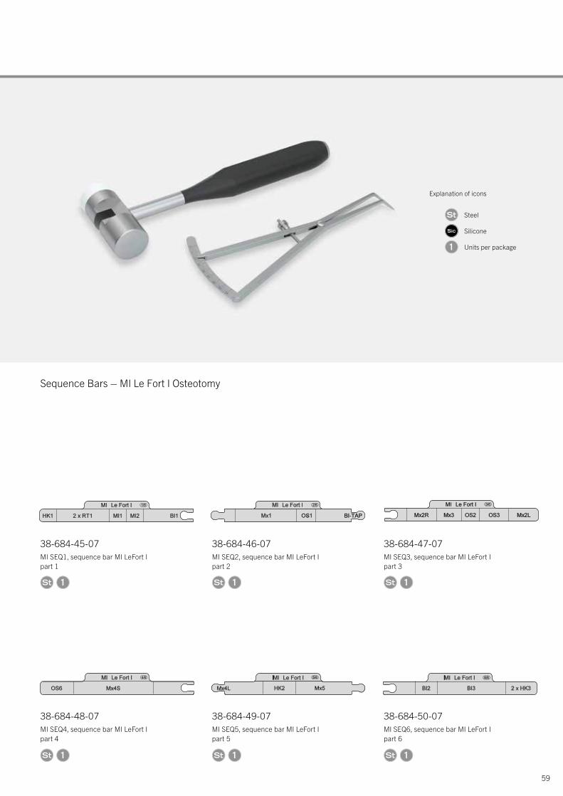
Sequence Bars – MI Le Fort I Osteotomy
38-684-48-07MI SEQ4, sequence bar MI LeFort I part 4
38-684-49-07MI SEQ5, sequence bar MI LeFort I part 5
38-684-50-07MI SEQ6, sequence bar MI LeFort I part 6
38-684-45-07MI SEQ1, sequence bar MI LeFort I part 1
38-684-46-07MI SEQ2, sequence bar MI LeFort I part 2
38-684-47-07MI SEQ3, sequence bar MI LeFort I part 3
38-684-44-0419 cm / 7 4⁄8"
BI-TAP, mallet Ø 25 mm, 260 g 1 1 1
1 1 1
3
3
3
3
3
3
Explanation of icons
Steel
Silicone
Units per package1
60
L1® MI Orthognathics | Product Range
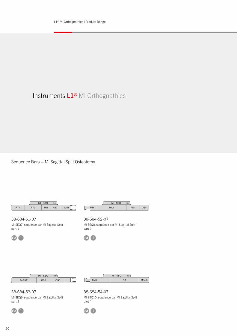
Sequence Bars – MI Sagittal Split Osteotomy
Instruments L1® MI Orthognathics
38-684-53-07MI SEQ9, sequence bar MI Sagittal Split part 3
38-684-54-07MI SEQ10, sequence bar MI Sagittal Split part 4
38-684-51-07MI SEQ7, sequence bar MI Sagittal Split part 1
38-684-52-07MI SEQ8, sequence bar MI Sagittal Split part 2
1 1
1 1
3
3
3
3
61
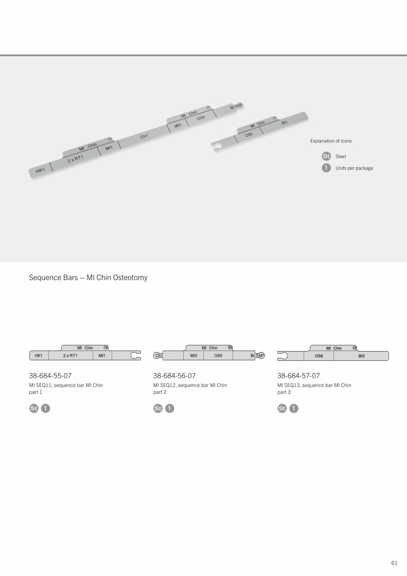
Sequence Bars – MI Chin Osteotomy
Explanation of icons
Steel
Units per package1
38-684-55-07MI SEQ11, sequence bar MI Chin part 1
38-684-56-07MI SEQ12, sequence bar MI Chin part 2
38-684-57-07MI SEQ13, sequence bar MI Chin part 3
1 1 1
3 3 3
62
L1® MI Orthognathics | Product Range
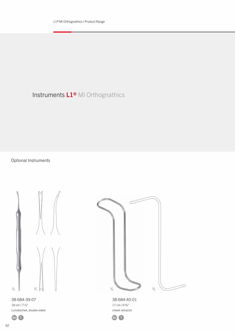
Optional Instruments
38-684-39-0718 cm / 7 1⁄8"
Luniatschek, double-sided
38-684-40-0117 cm / 6 6⁄8"
cheek retractor
48
Instruments L1® MI Orthognathics
1 1
1⁄2 1⁄1
1⁄2 1⁄2
63
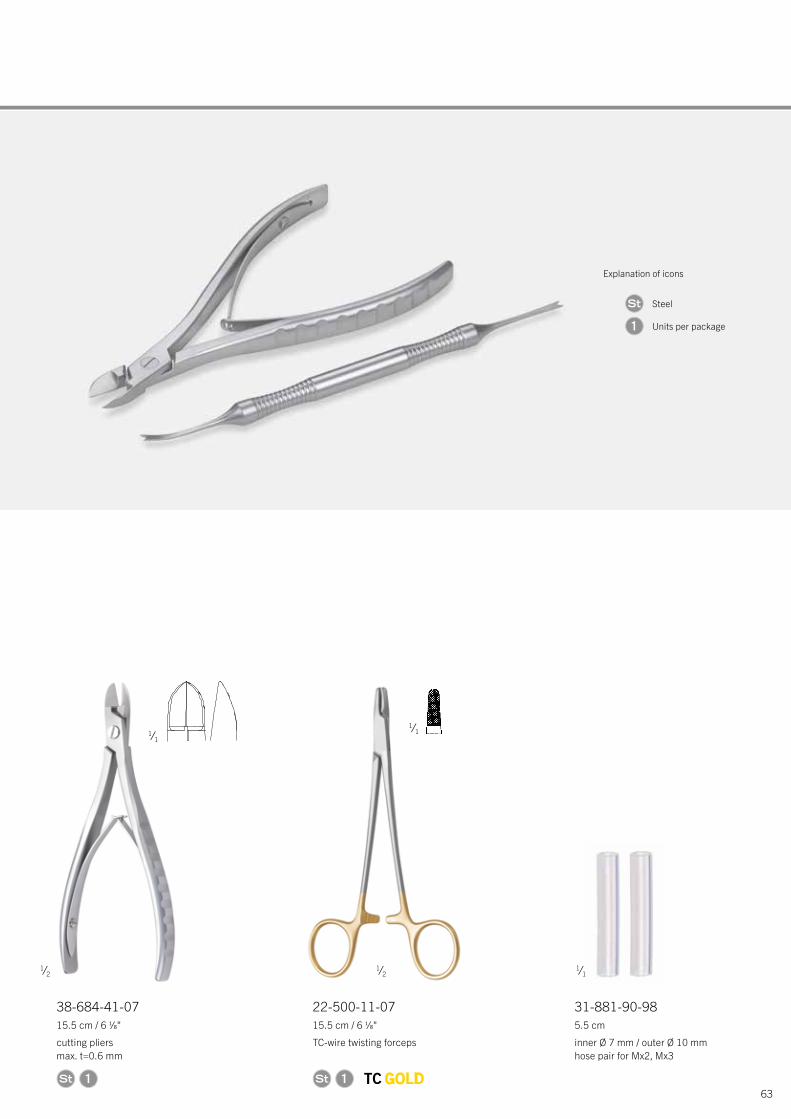
38-684-41-0715.5 cm / 6 1⁄8"
cutting pliers max. t=0.6 mm
22-500-11-0715.5 cm / 6 1⁄8"
TC-wire twisting forceps
31-881-90-985.5 cm
inner Ø 7 mm / outer Ø 10 mm hose pair for Mx2, Mx3
1 1
1⁄2 1⁄2
1⁄1
1⁄1 1⁄1
Explanation of icons
Steel
Units per package1
64
L1® MI Orthognathics | Product Range
Storage L1® MI Orthognathics
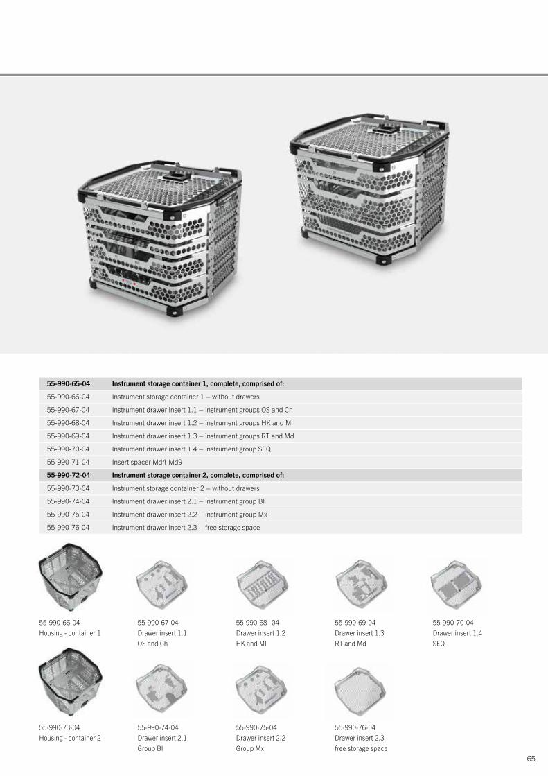
L1® MI Orthognathics comprises of two instrument storage containers.
Both storage containers are based on a drawer design. Set 1 has four drawers and Set 2 has three drawers. As a result, all 34 instruments can be stored according to their marking. In addition, an open storage space enables the addition of more instruments to suit custom requirements.
The necessary sequence template is always the first to be removed from instrument set 1 in the SEQ drawer. Together with the sequence template the instruments required for the particular intervention can be removed from the storage container and arranged according to the surgical workflow.
Storage baskets and drawer inserts can be ordered separately or as a complete storage container set.
65
55-990-65-04 Instrument storage container 1, complete, comprised of:
55-990-66-04 Instrument storage container 1 – without drawers
55-990-67-04 Instrument drawer insert 1.1 – instrument groups OS and Ch
55-990-68-04 Instrument drawer insert 1.2 – instrument groups HK and MI
55-990-69-04 Instrument drawer insert 1.3 – instrument groups RT and Md
55-990-70-04 Instrument drawer insert 1.4 – instrument group SEQ
55-990-71-04 Insert spacer Md4-Md9
55-990-72-04 Instrument storage container 2, complete, comprised of:
55-990-73-04 Instrument storage container 2 – without drawers
55-990-74-04 Instrument drawer insert 2.1 – instrument group BI
55-990-75-04 Instrument drawer insert 2.2 – instrument group Mx
55-990-76-04 Instrument drawer insert 2.3 – free storage space
55-990-69-04 Drawer insert 1.3RT and Md
55-990-76-04Drawer insert 2.3free storage space
55-990-70-04 Drawer insert 1.4SEQ
55-990-67-04 Drawer insert 1.1OS and Ch
55-990-74-04Drawer insert 2.1Group BI
55-990-68--04 Drawer insert 1.2HK and MI
55-990-75-04 Drawer insert 2.2Group Mx
55-990-66-04Housing - container 1
55-990-73-04Housing - container 2
66
L1® MI Orthognathics | Product Range
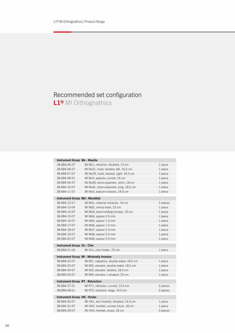
Recommended set configuration L1® MI Orthognathics
Instrument Group Mx - Maxilla 38-684-05-07 MI Mx1, retractor, doubled, 14 cm 1 piece38-684-06-07 MI Mx2L, hook, twisted, left, 16.5 cm 1 piece38-684-07-07 MI Mx2R, hook, twisted, right, 16.5 cm 1 piece38-684-08-01 MI Mx3, spatula, curved, 16 cm 1 piece38-684-09-07 MI Mx4S, bone expander, short, 18 cm 1 piece38-684-10-07 MI Mx4L, bone expander, long, 18.5 cm 1 piece38-684-11-07 MI Mx5, septum scissors, 18.5 cm 1 piece
Instrument Group Md - Mandible 38-684-12-07 MI Md1, channel retractor, 16 cm 2 pieces38-684-13-04 MI Md2, ramus hook, 23 cm 1 piece38-684-14-07 MI Md3, bone holding forceps, 19 cm 1 piece38-684-15-07 MI Md4, spacer 0.5 mm 1 piece38-684-16-07 MI Md5, spacer 1.0 mm 1 piece38-684-17-07 MI Md6, spacer 1.5 mm 1 piece38-684-18-07 MI Md7, spacer 2.0 mm 1 piece38-684-19-07 MI Md8, spacer 2.5 mm 1 piece38-684-20-07 MI Md9, spacer 3.0 mm 1 piece
Instrument Group Ch - Chin 38-684-21-04 MI Ch1, chin holder, 23 cm 1 piece
Instrument Group MI - Minimally Invasive 38-684-22-07 MI MI1, raspatory, double-sided, 18.5 cm 1 piece38-684-23-07 MI MI2, elevator, double-sided, 18.5 cm 1 piece38-684-24-07 MI MI3, elevator, twisted, 18.5 cm 1 piece38-684-25-07 MI MI4, elevator, v-shaped, 20 cm 1 piece
Instrument Group RT - Retractors 38-684-27-01 MI RT1, retractor, curved, 13.5 cm 2 pieces38-684-28-01 MI RT2, retractor, large, 16.5 cm 2 pieces
Instrument Group HK - Hooks 38-684-30-07 MI HK1, skin hooklet, doubled, 15.5 cm 1 piece38-684-31-07 MI HK2, hooklet, curved, blunt, 18 cm 1 piece38-684-29-07 MI HK3, hooklet, sharp, 18 cm 2 pieces
67
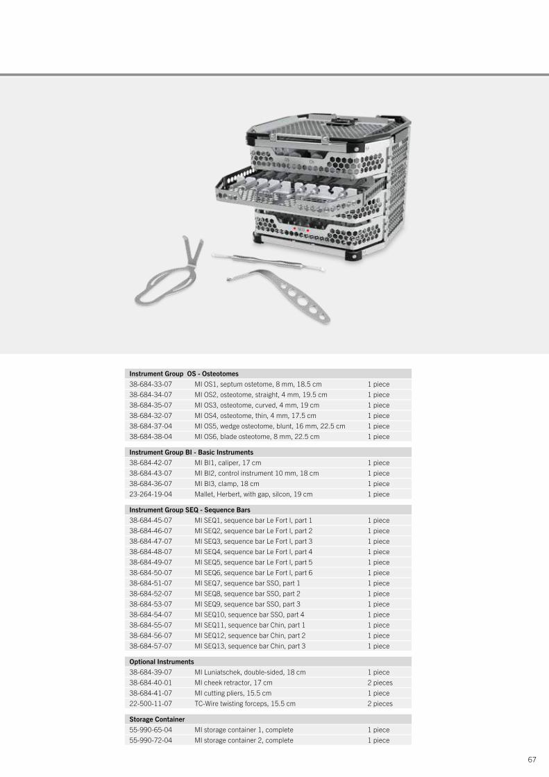
Instrument Group OS - Osteotomes 38-684-33-07 MI OS1, septum ostetome, 8 mm, 18.5 cm 1 piece38-684-34-07 MI OS2, osteotome, straight, 4 mm, 19.5 cm 1 piece38-684-35-07 MI OS3, osteotome, curved, 4 mm, 19 cm 1 piece38-684-32-07 MI OS4, osteotome, thin, 4 mm, 17.5 cm 1 piece38-684-37-04 MI OS5, wedge osteotome, blunt, 16 mm, 22.5 cm 1 piece38-684-38-04 MI OS6, blade osteotome, 8 mm, 22.5 cm 1 piece
Instrument Group BI - Basic Instruments 38-684-42-07 MI BI1, caliper, 17 cm 1 piece38-684-43-07 MI BI2, control instrument 10 mm, 18 cm 1 piece38-684-36-07 MI BI3, clamp, 18 cm 1 piece23-264-19-04 Mallet, Herbert, with gap, silcon, 19 cm 1 piece
Instrument Group SEQ - Sequence Bars 38-684-45-07 MI SEQ1, sequence bar Le Fort I, part 1 1 piece38-684-46-07 MI SEQ2, sequence bar Le Fort I, part 2 1 piece38-684-47-07 MI SEQ3, sequence bar Le Fort I, part 3 1 piece38-684-48-07 MI SEQ4, sequence bar Le Fort I, part 4 1 piece38-684-49-07 MI SEQ5, sequence bar Le Fort I, part 5 1 piece38-684-50-07 MI SEQ6, sequence bar Le Fort I, part 6 1 piece38-684-51-07 MI SEQ7, sequence bar SSO, part 1 1 piece38-684-52-07 MI SEQ8, sequence bar SSO, part 2 1 piece38-684-53-07 MI SEQ9, sequence bar SSO, part 3 1 piece38-684-54-07 MI SEQ10, sequence bar SSO, part 4 1 piece38-684-55-07 MI SEQ11, sequence bar Chin, part 1 1 piece38-684-56-07 MI SEQ12, sequence bar Chin, part 2 1 piece38-684-57-07 MI SEQ13, sequence bar Chin, part 3 1 piece
Optional Instruments 38-684-39-07 MI Luniatschek, double-sided, 18 cm 1 piece38-684-40-01 MI cheek retractor, 17 cm 2 pieces38-684-41-07 MI cutting pliers, 15.5 cm 1 piece22-500-11-07 TC-Wire twisting forceps, 15.5 cm 2 pieces
Storage Container 55-990-65-04 MI storage container 1, complete 1 piece55-990-72-04 MI storage container 2, complete 1 piece
L1® MI Orthognathics | Product Range
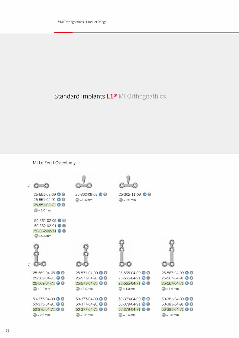
Standard Implants L1® MI Orthognathics
MI Le Fort I Osteotomy
1⁄1
25-569-04-09 unit(s)5 25-569-04-91 1 25-569-04-71 1
= 1.0 mm
50-375-04-09 unit(s)5 50-375-04-91 1 50-375-04-71 1
= 0.6 mm
25-571-04-09 unit(s)5 25-571-04-91 1 25-571-04-71 1
= 1.0 mm
50-377-04-09 unit(s)5 50-377-04-91 1 50-377-04-71 1
= 0.6 mm
25-565-04-09 unit(s)5
25-565-04-91 1
25-565-04-71 1
= 1.0 mm
50-379-04-09 unit(s)5
50-379-04-91 1
50-379-04-71 1 = 0.6 mm
25-567-04-09 unit(s)5
25-567-04-91 1
25-567-04-71 1
= 1.0 mm
50-381-04-09 unit(s)5
50-381-04-91 1
50-381-04-71 1 = 0.6 mm
1⁄1
25-551-02-09 unit(s)5 25-551-02-91 1 25-551-02-71 1
= 1.0 mm
25-302-09-09 unit(s)5 = 0.6 mm
25-302-11-09 unit(s)5 = 0.6 mm
50-362-02-09 unit(s)5 50-362-02-91 1 50-362-02-71 1
= 0.6 mm
68
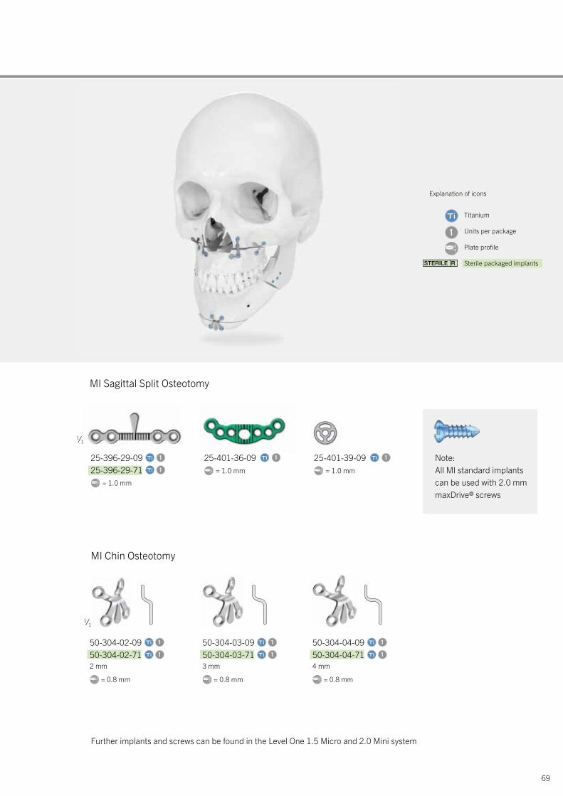
69
1⁄1
25-396-29-09 1 25-396-29-71 1
= 1.0 mm
MI Sagittal Split Osteotomy
MI Chin Osteotomy
Further implants and screws can be found in the Level One 1.5 Micro and 2.0 Mini system
Note:All MI standard implants can be used with 2.0 mm maxDrive® screws
1⁄1
50-304-02-09 1 50-304-02-71 1 2 mm
= 0.8 mm
50-304-03-09 1 50-304-03-71 1 3 mm
= 0.8 mm
50-304-04-09 1 50-304-04-71 1 4 mm
= 0.8 mm
25-401-36-09 1 = 1.0 mm
25-401-39-09 1 = 1.0 mm
Explanation of icons
Titanium
Units per package
Plate profile
Sterile packaged implants
1

70
Overview: Individual Patient Solutions
Prof. Dr. Dr.Gwen R.J. Swennen, Bruges, Belgium
“After 20 years of personal experience with 3D virtual planning, I think that with IPS CaseDesigner® the next level of 3D virtual CMF planning software has been reached. As a part of its development I am sure it will further improve patient care in the future.”
3D Virtual Treatment Planning of Orthognathic Surgery.A Step-by-Step Approach for Orthodontists and Surgeons.Springer.
IPS CaseDesigner®
The IPS CaseDesigner® makes 3D virtual surgical planning easier and faster than ever before. With this brand-new, flexible software tool, planning and simulating surgical interventions become efficient and reliable. Individualized treatment concepts can be easily transferred through a virtual approach towards patients in the operating theater.
While the IPS CaseDesigner® software is covering multiple sub-specialties of maxillofacial surgery, the first commer- cially available module is focusing on orthognathic surgery.It offers an intuitive and straightforward approach to virtual orthognathic planning by guiding the user through a step-by-step workflow.
Recommended computer specifications
■ Broadband internet connection■ Windows 10, 64 bit or Mac OS X Yosemite or higher■ Good graphics card (NVIDIA, AMD)■ HD screen resolution■ Min. 8 GB RAM
The IPS® Product Family
71
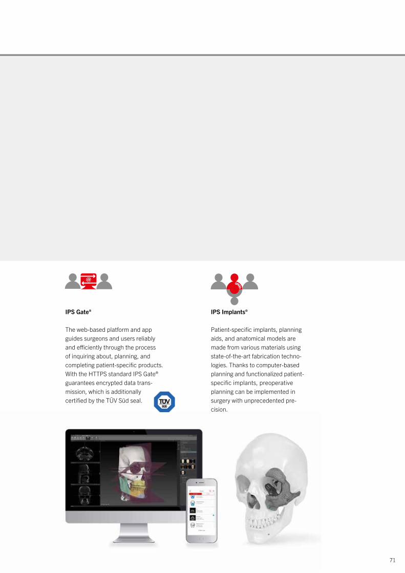
IPS Gate®
The web-based platform and app guides surgeons and users reliably and efficiently through the process of inquiring about, planning, and completing patient-specific products. With the HTTPS standard IPS Gate® guarantees encrypted data trans- mission, which is additionally certified by the TÜV Süd seal.
IPS Implants®
Patient-specific implants, planning aids, and anatomical models are made from various materials using state-of-the-art fabrication techno- logies. Thanks to computer-based planning and functionalized patient- specific implants, preoperative planning can be implemented in surgery with unprecedented pre- cision.
Gebrüder Martin GmbH and Co. KGA company of the KLS Martin GroupKLS Martin Platz 1 · 78532 Tuttlingen · Germany P.O. Box 60 · 78501 Tuttlingen · GermanyTel. +49 7461 706-0 · Fax +49 7461 [email protected] · www.klsmartin.com
08.19 · 90-345-02-04 · Printed in Germany · Copyright by Gebrüder Martin GmbH and Co. KG · Alle Rechte vorbehalten · Technische Änderungen vorbehalten We reserve the right to make alterations · Cambios técnicos reservados · Sous réserve de modifications techniques · Ci riserviamo il diritto di modifiche tecniche
KLS Martin Group
KLS Martin Australia Pty Ltd.Sydney · AustraliaTel. +61 2 9439 [email protected]
KLS Martin do Brasil Ltda.São Paulo · BrazilTel. +55 11 3554 [email protected]
KLS Martin Medical (Shanghai) International Trading Co. Ltd.Shanghai · ChinaTel. +86 21 5820 [email protected]
KLS Martin India Pvt Ltd.Chennai · India Tel. +91 44 66 442 [email protected]
Martin Italia S.r.l.Milan · ItalyTel. +39 039 605 67 [email protected]
Nippon Martin K.K.Tokyo · JapanTel. +81 3 3814 [email protected]
KLS Martin SE Asia Sdn. Bhd.Penang · Malaysia Tel. +604 505 [email protected]
KLS Martin de México S.A. de C.V.Mexico City · [email protected]
Martin Nederland/Marned B.V.Huizen · The Netherlands Tel. +31 35 523 45 [email protected]
Gebrüder Martin GmbH & Co. KGMoscow · RussiaTel. +7 499 [email protected]
KLS Martin Taiwan Ltd.Taipei 106 · TaiwanTel. +886 2 2325 [email protected]
Gebrüder Martin GmbH & Co. KGDubai · United Arab Emirates Tel. +971 4 454 16 [email protected]
KLS Martin UK Ltd. London · United Kingdom Tel. +44 1189 000 [email protected]
KLS Martin LP Jacksonville · Florida, USA Tel. +1 904 641 77 [email protected]