Embed Size (px)
Citation preview
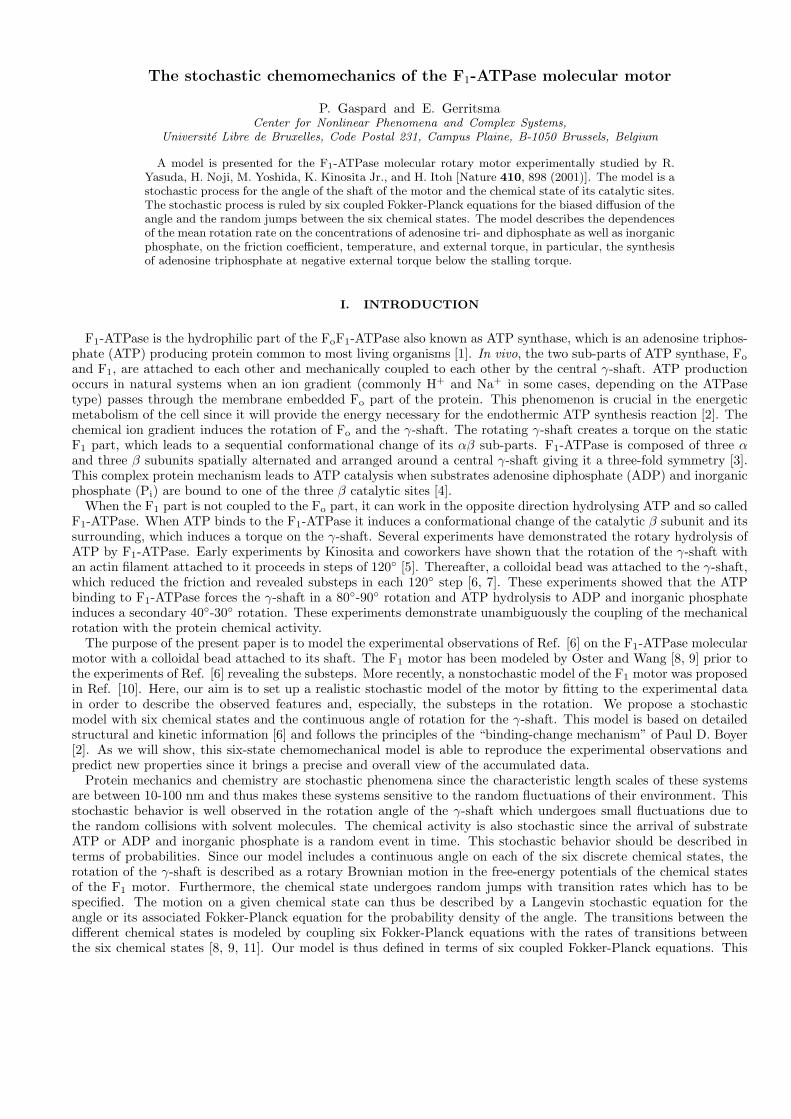
The stochastic chemomechanics of the F1-ATPase molecular motor
P. Gaspard and E. GerritsmaCenter for Nonlinear Phenomena and Complex Systems,
Universite Libre de Bruxelles, Code Postal 231, Campus Plaine, B-1050 Brussels, Belgium
A model is presented for the F1-ATPase molecular rotary motor experimentally studied by R.Yasuda, H. Noji, M. Yoshida, K. Kinosita Jr., and H. Itoh [Nature 410, 898 (2001)]. The model is astochastic process for the angle of the shaft of the motor and the chemical state of its catalytic sites.The stochastic process is ruled by six coupled Fokker-Planck equations for the biased diffusion of theangle and the random jumps between the six chemical states. The model describes the dependencesof the mean rotation rate on the concentrations of adenosine tri- and diphosphate as well as inorganicphosphate, on the friction coefficient, temperature, and external torque, in particular, the synthesisof adenosine triphosphate at negative external torque below the stalling torque.
I. INTRODUCTION
F1-ATPase is the hydrophilic part of the FoF1-ATPase also known as ATP synthase, which is an adenosine triphos-phate (ATP) producing protein common to most living organisms [1]. In vivo, the two sub-parts of ATP synthase, Fo
and F1, are attached to each other and mechanically coupled to each other by the central γ-shaft. ATP productionoccurs in natural systems when an ion gradient (commonly H+ and Na+ in some cases, depending on the ATPasetype) passes through the membrane embedded Fo part of the protein. This phenomenon is crucial in the energeticmetabolism of the cell since it will provide the energy necessary for the endothermic ATP synthesis reaction [2]. Thechemical ion gradient induces the rotation of Fo and the γ-shaft. The rotating γ-shaft creates a torque on the staticF1 part, which leads to a sequential conformational change of its αβ sub-parts. F1-ATPase is composed of three αand three β subunits spatially alternated and arranged around a central γ-shaft giving it a three-fold symmetry [3].This complex protein mechanism leads to ATP catalysis when substrates adenosine diphosphate (ADP) and inorganicphosphate (Pi) are bound to one of the three β catalytic sites [4].
When the F1 part is not coupled to the Fo part, it can work in the opposite direction hydrolysing ATP and so calledF1-ATPase. When ATP binds to the F1-ATPase it induces a conformational change of the catalytic β subunit and itssurrounding, which induces a torque on the γ-shaft. Several experiments have demonstrated the rotary hydrolysis ofATP by F1-ATPase. Early experiments by Kinosita and coworkers have shown that the rotation of the γ-shaft withan actin filament attached to it proceeds in steps of 120◦ [5]. Thereafter, a colloidal bead was attached to the γ-shaft,which reduced the friction and revealed substeps in each 120◦ step [6, 7]. These experiments showed that the ATPbinding to F1-ATPase forces the γ-shaft in a 80◦-90◦ rotation and ATP hydrolysis to ADP and inorganic phosphateinduces a secondary 40◦-30◦ rotation. These experiments demonstrate unambiguously the coupling of the mechanicalrotation with the protein chemical activity.
The purpose of the present paper is to model the experimental observations of Ref. [6] on the F1-ATPase molecularmotor with a colloidal bead attached to its shaft. The F1 motor has been modeled by Oster and Wang [8, 9] prior tothe experiments of Ref. [6] revealing the substeps. More recently, a nonstochastic model of the F1 motor was proposedin Ref. [10]. Here, our aim is to set up a realistic stochastic model of the motor by fitting to the experimental datain order to describe the observed features and, especially, the substeps in the rotation. We propose a stochasticmodel with six chemical states and the continuous angle of rotation for the γ-shaft. This model is based on detailedstructural and kinetic information [6] and follows the principles of the “binding-change mechanism” of Paul D. Boyer[2]. As we will show, this six-state chemomechanical model is able to reproduce the experimental observations andpredict new properties since it brings a precise and overall view of the accumulated data.
Protein mechanics and chemistry are stochastic phenomena since the characteristic length scales of these systemsare between 10-100 nm and thus makes these systems sensitive to the random fluctuations of their environment. Thisstochastic behavior is well observed in the rotation angle of the γ-shaft which undergoes small fluctuations due tothe random collisions with solvent molecules. The chemical activity is also stochastic since the arrival of substrateATP or ADP and inorganic phosphate is a random event in time. This stochastic behavior should be described interms of probabilities. Since our model includes a continuous angle on each of the six discrete chemical states, therotation of the γ-shaft is described as a rotary Brownian motion in the free-energy potentials of the chemical statesof the F1 motor. Furthermore, the chemical state undergoes random jumps with transition rates which has to bespecified. The motion on a given chemical state can thus be described by a Langevin stochastic equation for theangle or its associated Fokker-Planck equation for the probability density of the angle. The transitions between thedifferent chemical states is modeled by coupling six Fokker-Planck equations with the rates of transitions betweenthe six chemical states [8, 9, 11]. Our model is thus defined in terms of six coupled Fokker-Planck equations. This
2
stochastic process can be numerically simulated by Gillespie’s algorithm [12–14].The transition rates of the reactions are established on the basis of the chemical kinetics thanks to Arrhenius’
law and mass action law. Each reaction proceeds via some transition state in the free-energy landscape. Eachtransition state is characterized by its activation energy. The thermal activation above the energy barrier determinesthe speed of each reaction. We show that the knowledge of the free-energy potentials of both the chemical statesand the transition states is essential to describe the chemomechanical properties of the F1 motor. The free-energypotentials of the chemical states alone do not suffice for this purpose. Indeed, the transition states determine thetime scales of the reactions and the nonequilibrium thermodynamics of the molecular motor. A central role is playedby the thermodynamic forces or affinities [15], which drive the mean motion of the motor. These affinities arise ifthe concentrations of the reactants and products of ATP hydrolysis are away from their equilibrium values or if anexternal torque is applied to the motor. The dependences of the mean rotation rate of the motor on these affinitiesare therefore important questions to answer to understand the nonequilibrium thermodynamics of the motor. In thisregard, other important questions concern the synthesis of ATP by an external torque, which has been experimentallyachieved [16]. Moreover, we address the question whether the motor works with a mechanism of tight or loose couplingbetween the input (i.e., the flux of ATP molecules) and the output (i.e., the rotation of the motor shaft) [17].
The paper is organized as follows. The model is presented in Sec. II. The dependence of the rotation on ATPconcentration is studied in Sec. III. The effects of friction and temperature are discussed in Sec. IV. In Sec. V, wedescribe the behavior of the motor in the presence of the products of ATP hydrolysis. Section VI is devoted to theeffect of an external torque on the motor. Conclusions are drawn in Sec. VII.
II. THE SIX-STATE MODEL OF THE F1-ATPase MOTOR
A. The chemistry of F1-ATPase
The rotation of the F1-ATPase motor is driven by the hydrolysis of adenosine triphosphate (ATP) into adenosinediphosphate (ADP) and inorganic phosphate (Pi):
ATP ADP + Pi (1)
The equilibrium standard Gibbs free energy of hydrolysis is ∆G0 = −30.5 kJ/mol = −7.3 kcal/mol = −50 pN nm sothat the equilibrium concentrations satisfy
[ATP]eq[ADP]eq[Pi]eq
= exp∆G0
kBT' 4.89 10−6 M−1 (2)
at the temperature of 23 degrees Celsius. This shows that the products of ATP hydrolysis are favored. The motor isin a nonequilibrium state if the concentrations do not satisfy Eq. (2), whereupon its mean rotation becomes possible.We notice that the mean rotation rate should vanish at equilibrium.
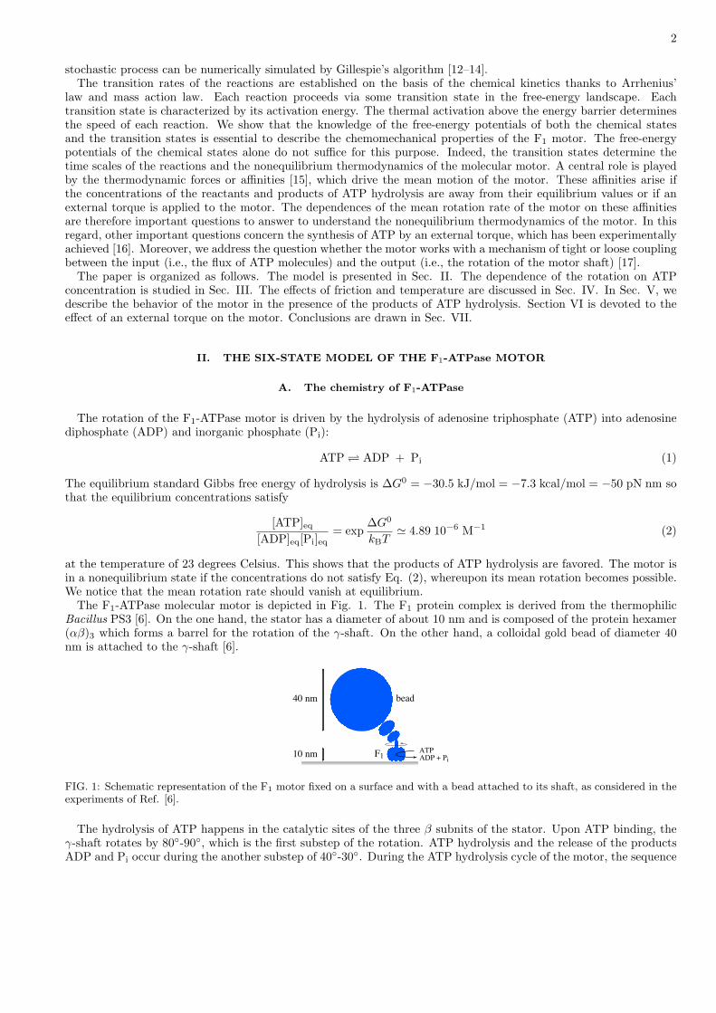
The F1-ATPase molecular motor is depicted in Fig. 1. The F1 protein complex is derived from the thermophilicBacillus PS3 [6]. On the one hand, the stator has a diameter of about 10 nm and is composed of the protein hexamer(αβ)3 which forms a barrel for the rotation of the γ-shaft. On the other hand, a colloidal gold bead of diameter 40nm is attached to the γ-shaft [6].
10 nm
40 nm bead
F1 ADP + Pi
ATP
FIG. 1: Schematic representation of the F1 motor fixed on a surface and with a bead attached to its shaft, as considered in theexperiments of Ref. [6].
The hydrolysis of ATP happens in the catalytic sites of the three β subnits of the stator. Upon ATP binding, theγ-shaft rotates by 80◦-90◦, which is the first substep of the rotation. ATP hydrolysis and the release of the productsADP and Pi occur during the another substep of 40◦-30◦. During the ATP hydrolysis cycle of the motor, the sequence
3
of reactions is coupled to the unidirectional rotation of the γ-shaft. The reversed rotation is accompanied by ATPsynthesis.
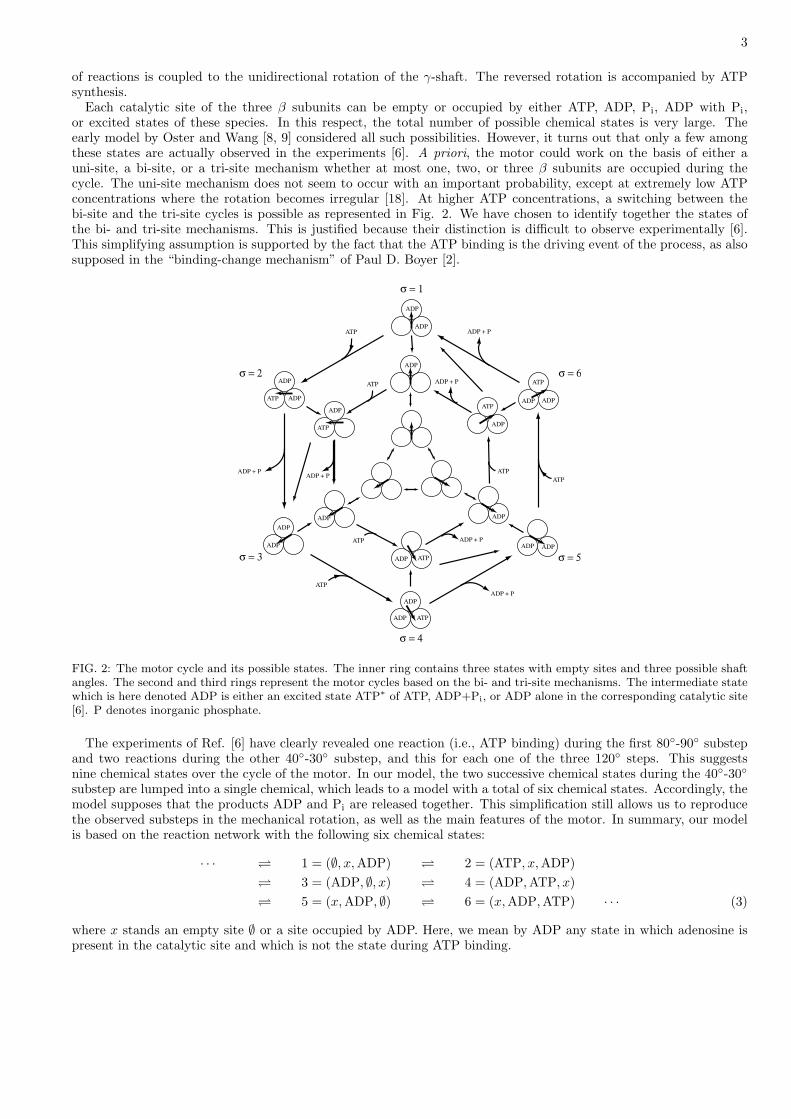
Each catalytic site of the three β subunits can be empty or occupied by either ATP, ADP, Pi, ADP with Pi,or excited states of these species. In this respect, the total number of possible chemical states is very large. Theearly model by Oster and Wang [8, 9] considered all such possibilities. However, it turns out that only a few amongthese states are actually observed in the experiments [6]. A priori, the motor could work on the basis of either auni-site, a bi-site, or a tri-site mechanism whether at most one, two, or three β subunits are occupied during thecycle. The uni-site mechanism does not seem to occur with an important probability, except at extremely low ATPconcentrations where the rotation becomes irregular [18]. At higher ATP concentrations, a switching between thebi-site and the tri-site cycles is possible as represented in Fig. 2. We have chosen to identify together the states ofthe bi- and tri-site mechanisms. This is justified because their distinction is difficult to observe experimentally [6].This simplifying assumption is supported by the fact that the ATP binding is the driving event of the process, as alsosupposed in the “binding-change mechanism” of Paul D. Boyer [2].
ADP
ADP
ATP
ATP
ADP
ADP
ADP
ADP
ADP
ATP
ADPATP
ADP
ADP
ADP
ADP
ADP
ADP
ATPADP
ADP
ADP ADP
ATP
ATP
ADP + PADP + P
ATP
ATP
ATP
ATP
ATP
ADP + P
ADP + P
ADP + P
ADP + P
σ = 1
σ = 4
σ = 2
σ = 3
σ = 6
σ = 5
FIG. 2: The motor cycle and its possible states. The inner ring contains three states with empty sites and three possible shaftangles. The second and third rings represent the motor cycles based on the bi- and tri-site mechanisms. The intermediate statewhich is here denoted ADP is either an excited state ATP∗ of ATP, ADP+Pi, or ADP alone in the corresponding catalytic site[6]. P denotes inorganic phosphate.
The experiments of Ref. [6] have clearly revealed one reaction (i.e., ATP binding) during the first 80◦-90◦ substepand two reactions during the other 40◦-30◦ substep, and this for each one of the three 120◦ steps. This suggestsnine chemical states over the cycle of the motor. In our model, the two successive chemical states during the 40◦-30◦substep are lumped into a single chemical, which leads to a model with a total of six chemical states. Accordingly, themodel supposes that the products ADP and Pi are released together. This simplification still allows us to reproducethe observed substeps in the mechanical rotation, as well as the main features of the motor. In summary, our modelis based on the reaction network with the following six chemical states:
· · · 1 = (∅, x,ADP) 2 = (ATP, x,ADP) 3 = (ADP, ∅, x) 4 = (ADP,ATP, x) 5 = (x, ADP, ∅) 6 = (x, ADP,ATP) · · · (3)
where x stands an empty site ∅ or a site occupied by ADP. Here, we mean by ADP any state in which adenosine ispresent in the catalytic site and which is not the state during ATP binding.
4
B. The mechanics of F1-ATPase
In each chemical state σ, the shaft of the motor is submitted to an internal torque caused by some free-energypotential Uσ(θ) which depends on the angle θ. We notice that the experiment is carried out at constant atmosphericpressure so that we are here talking about Gibbs free energies. Moreover, the molecular fluctuations induce a randomtorque τfluct(t) due to the environment. The motion of this angle is thus described by an overdamped Langevin-typeequation
ζdθ
dt= −∂Uσ
∂θ+ τext + τfluct(t) (4)
where τext is some external torque. The fluctuating torque is taken as a Gaussian white noise related to the frictioncoefficient ζ according to the fluctuation-dissipation theorem:
〈τfluct(t)〉 = 0 (5)〈τfluct(t)τfluct(t′)〉 = 2 kBT ζ δ(t− t′) (6)
The friction is due to the viscosity η = 10−9 pN s nm−2 of the water in which the bead or the filament attachedto the shaft moves. The contribution from the friction internal to the motor is neglected. Accordingly, the frictioncoefficient is given by:
ζ = 8πηr3 + 6πηrx2 (7)
for a bead of radius r attached off axis with its center at the distance x from the rotation axis [6, 19]; by
ζ = 16πηr3 + 6πηrx21 + 6πηrx2
2 (8)
for bead duplex of radii r at distances x1 and x2 from the rotation axis [6]; and by
ζ =4π
3ηl3
ln l2r + γr
(9)
for an actin filament supposed to be a cylinder of length l and radius r attached perpendicularly by one of its ends tothe shaft with γr = −0.55± 0.11 [20].
C. Coupling the chemistry to the mechanics
During the time evolution of the motor, reactive events happen randomly. The chemical state σ and its associatedpotential Uσ change accordingly at each one of these random events. The mechanical motion of the shaft is thuscoupled to the chemical reaction in such chemomechanical processes. The state of the system is described by theprobability density pσ(θ, t) to find the motor in the chemical state σ with its shaft forming the angle θ at time t. Thetime evolution of the probability densities is ruled by a set of coupled Fokker-Planck equations including terms forthe description the random jumps between the discrete chemical states σ:
∂t pσ(θ, t) + ∂θ Jσ(θ, t) =∑
ρ,σ′( 6=σ)
[pσ′(θ, t) Wρ,σ′→σ(θ)− pσ(θ, t) W−ρ,σ→σ′(θ)] (10)
with the probability current densities
Jσ = −D ∂θ pσ +1ζ
(−∂θUσ + τext) pσ (11)
given in terms of the diffusion coefficient
D =kBT
ζ(12)
and the deterministic torque −∂θUσ + τext which biases the random rotation [11]. The index ρ denotes the differentchemical reactions undergone by the motor. The left-hand sides of Eqs. (10) describe the mechanics and theirright-hand sides the reactions.
5
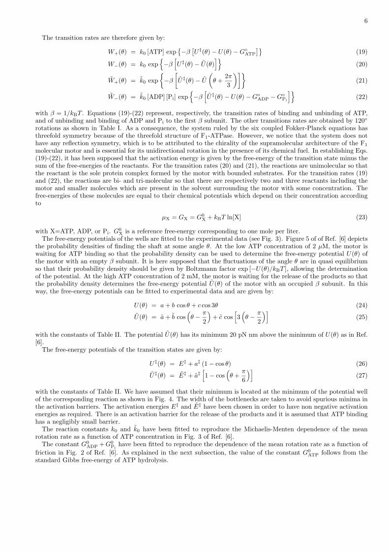
TABLE I: Table showing the different chemical states σ = 1, 2, ..., 6, their free-energy potentials Uσ(θ), the forward andbackward transition rates and the corresponding transition states by their free-energy potentials U‡
σ(θ).
state σ potential Uσ(θ) transition state forward transition rate backward transition rate
U‡(θ) ↓ W+(θ) ↑ W−(θ)
1 U(θ) 1 1
U‡(θ) ↓ W+(θ) ↑ W−(θ)
2 U(θ) 2 2
U‡ `θ − 2π
3
´↓ W+
`θ − 2π
3
´↑ W−
`θ − 2π
3
´3 U
`θ − 2π
3
´3 3
U‡ `θ − 2π
3
´↓ W+
`θ − 2π
3
´↑ W−
`θ − 2π
3
´4 U
`θ − 2π
3
´4 4
U‡ `θ − 4π
3
´↓ W+
`θ − 4π
3
´↑ W−
`θ − 4π
3
´5 U
`θ − 4π
3
´5 5
U‡ `θ − 4π
3
´↓ W+
`θ − 4π
3
´↑ W−
`θ − 4π
3
´6 U
`θ − 4π
3
´6 6
Since there are six chemical states and two chemical reactions (ATP binding and release of the products) and thecorresponding reversed reactions, the model is defined by the following six coupled Fokker-Planck equations:
∂t p2i+1 + ∂θ J2i+1 = −[W+
(θ − 2πi
3
)+ W−
(θ − 2πi
3
)]p2i+1
+W−
(θ − 2πi
3
)p2i+2 + W+
(θ − 2πi
3
)p2i (13)
∂t p2i+2 + ∂θ J2i+2 = −[W−
(θ − 2πi
3
)+ W+
(θ − 2π(i + 1)
3
)]p2i+2
+W+
(θ − 2πi
3
)p2i+1 + W−
(θ − 2π(i + 1)
3
)p2i+3 (14)
with i = 0, 1, 2. We make the identifications p0 = p6 and p7 = p1. The probability current densities Jσ(θ, t) aredefined by Eq. (11) for each given state σ = 1, 2, ..., 6.
The transition rates obey Arrhenius’ law of kinetics in terms of the activation energies of each reaction. Theseactivation energies are given by the difference between the free energy of the transition state of the reaction and thefree energy of the potential well of the initial state. The free-energy potentials of both the wells and the transitionstates depend on the angle θ of the shaft. The free energy of the transition state of ATP binding is denoted byU‡
1 (θ) = U‡(θ) and the one for the release of the products ADP and Pi by U‡2 (θ) = U‡(θ) for the first β subunit. The
free-energy potential of the state where the first β subunit is empty is denoted by U1(θ) = U(θ) and by U2(θ) = U(θ)if it is occupied. The potentials of the other states are obtained by 120◦ rotations according to:
U2i+1(θ) = U
(θ − 2πi
3
)(15)
U2i+2(θ) = U
(θ − 2πi
3
)(16)
U‡2i+1(θ) = U‡
(θ − 2πi
3
)(17)
U‡2i+2(θ) = U‡
(θ − 2πi
3
)(18)
with i = 0, 1, 2, as shown in Table I.
6
The transition rates are therefore given by:
W+(θ) = k0 [ATP] exp{−β
[U‡(θ)− U(θ)−G◦
ATP
]}(19)
W−(θ) = k0 exp{−β
[U‡(θ)− U(θ)
]}(20)
W+(θ) = k0 exp{−β
[U‡(θ)− U
(θ +
2π
3
)]}(21)
W−(θ) = k0 [ADP] [Pi] exp{−β
[U‡(θ)− U(θ)−G◦
ADP −G◦Pi
]}(22)
with β = 1/kBT . Equations (19)-(22) represent, respectively, the transition rates of binding and unbinding of ATP,and of unbinding and binding of ADP and Pi to the first β subunit. The other transitions rates are obtained by 120◦rotations as shown in Table I. As a consequence, the system ruled by the six coupled Fokker-Planck equations hasthreefold symmetry because of the threefold structure of F1-ATPase. However, we notice that the system does nothave any reflection symmetry, which is to be attributed to the chirality of the supramolecular architecture of the F1
molecular motor and is essential for its unidirectional rotation in the presence of its chemical fuel. In establishing Eqs.(19)-(22), it has been supposed that the activation energy is given by the free-energy of the transition state minus thesum of the free-energies of the reactants. For the transition rates (20) and (21), the reactions are unimolecular so thatthe reactant is the sole protein complex formed by the motor with bounded substrates. For the transition rates (19)and (22), the reactions are bi- and tri-molecular so that there are respectively two and three reactants including themotor and smaller molecules which are present in the solvent surrounding the motor with some concentration. Thefree-energies of these molecules are equal to their chemical potentials which depend on their concentration accordingto
µX = GX = G0X + kBT ln[X] (23)
with X=ATP, ADP, or Pi. G0X is a reference free-energy corresponding to one mole per liter.
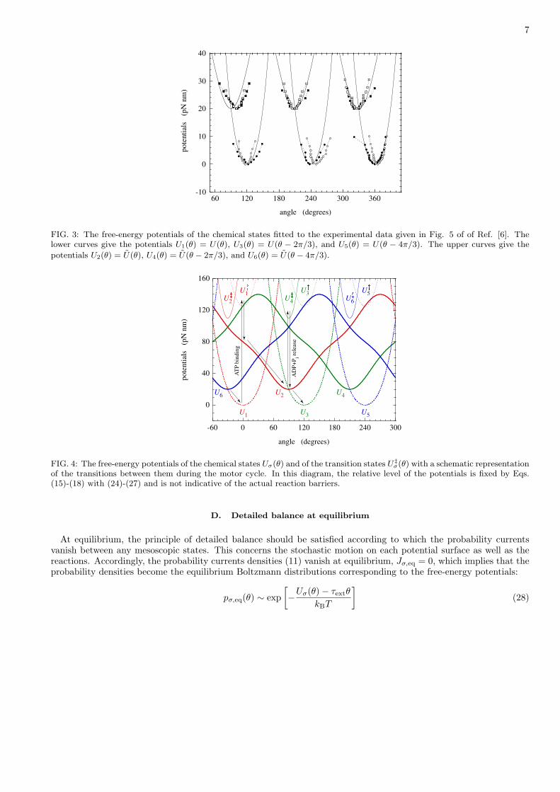
The free-energy potentials of the wells are fitted to the experimental data (see Fig. 3). Figure 5 of of Ref. [6] depictsthe probability densities of finding the shaft at some angle θ. At the low ATP concentration of 2 µM, the motor iswaiting for ATP binding so that the probability density can be used to determine the free-energy potential U(θ) ofthe motor with an empty β subunit. It is here supposed that the fluctuations of the angle θ are in quasi equilibriumso that their probability density should be given by Boltzmann factor exp [−U(θ)/kBT ], allowing the determinationof the potential. At the high ATP concentration of 2 mM, the motor is waiting for the release of the products so thatthe probability density determines the free-energy potential U(θ) of the motor with an occupied β subunit. In thisway, the free-energy potentials can be fitted to experimental data and are given by:
U(θ) = a + b cos θ + c cos 3θ (24)
U(θ) = a + b cos(θ − π
2
)+ c cos
[3
(θ − π
2
)](25)
with the constants of Table II. The potential U(θ) has its minimum 20 pN nm above the minimum of U(θ) as in Ref.[6].
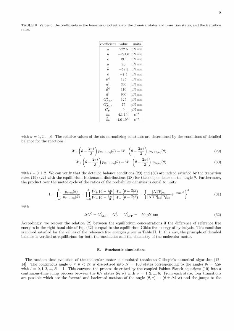
The free-energy potentials of the transition states are given by:
U‡(θ) = E‡ + a‡ (1− cos θ) (26)
U‡(θ) = E‡ + a‡[1− cos
(θ +
π
6
)](27)
with the constants of Table II. We have assumed that their minimum is located at the minimum of the potential wellof the corresponding reaction as shown in Fig. 4. The width of the bottlenecks are taken to avoid spurious minima inthe activation barriers. The activation energies E‡ and E‡ have been chosen in order to have non negative activationenergies as required. There is an activation barrier for the release of the products and it is assumed that ATP bindinghas a negligibly small barrier.
The reaction constants k0 and k0 have been fitted to reproduce the Michaelis-Menten dependence of the meanrotation rate as a function of ATP concentration in Fig. 3 of Ref. [6].
The constant G0ADP + G0
Pihave been fitted to reproduce the dependence of the mean rotation rate as a function of
friction in Fig. 2 of Ref. [6]. As explained in the next subsection, the value of the constant G0ATP follows from the
standard Gibbs free-energy of ATP hydrolysis.
7
-10
0
10
20
30
40
60 120 180 240 300 360
pote
nti
als
(p
N n
m)
angle (degrees)
FIG. 3: The free-energy potentials of the chemical states fitted to the experimental data given in Fig. 5 of of Ref. [6]. Thelower curves give the potentials U1(θ) = U(θ), U3(θ) = U(θ − 2π/3), and U5(θ) = U(θ − 4π/3). The upper curves give the
potentials U2(θ) = U(θ), U4(θ) = U(θ − 2π/3), and U6(θ) = U(θ − 4π/3).
0
40
80
120
160
-60 0 60 120 180 240 300
pote
nti
als
(p
N n
m)
angle (degrees)
U1
U2
U2
U1�
�
U3
U4
U4
U3�
�
U5
U6
U6
U5�
�
AT
P b
indin
g
AD
P+
Pi r
elea
se
FIG. 4: The free-energy potentials of the chemical states Uσ(θ) and of the transition states U‡σ(θ) with a schematic representation
of the transitions between them during the motor cycle. In this diagram, the relative level of the potentials is fixed by Eqs.(15)-(18) with (24)-(27) and is not indicative of the actual reaction barriers.
D. Detailed balance at equilibrium
At equilibrium, the principle of detailed balance should be satisfied according to which the probability currentsvanish between any mesoscopic states. This concerns the stochastic motion on each potential surface as well as thereactions. Accordingly, the probability currents densities (11) vanish at equilibrium, Jσ,eq = 0, which implies that theprobability densities become the equilibrium Boltzmann distributions corresponding to the free-energy potentials:
pσ,eq(θ) ∼ exp[−Uσ(θ)− τextθ
kBT
](28)
8
TABLE II: Values of the coefficients in the free-energy potentials of the chemical states and transition states, and the transitionrates.
coefficient value units
a 272.5 pN nm
b −291.6 pN nm
c 19.1 pN nm
a 80 pN nm
b −52.5 pN nm
c −7.5 pN nm
E‡ 125 pN nm
a‡ 360 pN nm
E‡ 110 pN nm
a‡ 900 pN nm
G0ATP 125 pN nm
G0ADP 75 pN nm
G0Pi
0 pN nm
k0 4.1 107 s−1
k0 4.0 1012 s−1
with σ = 1, 2, ..., 6. The relative values of the six normalizing constants are determined by the conditions of detailedbalance for the reactions:
W+
(θ − 2πi
3
)p2i+1,eq(θ) = W−
(θ − 2πi
3
)p2i+2,eq(θ) (29)
W+
(θ − 2πi
3
)p2i+1,eq(θ) = W−
(θ − 2πi
3
)p2i,eq(θ) (30)
with i = 0, 1, 2. We can verify that the detailed balance conditions (29) and (30) are indeed satisfied by the transitionrates (19)-(22) with the equilibrium Boltzmann distributions (28) for their dependence on the angle θ. Furthermore,the product over the motor cycle of the ratios of the probability densities is equal to unity:
1 =6∏
σ=1
pσ,eq(θ)pσ−1,eq(θ)
=2∏
i=0
W+
(θ − 2πi
3
)W+
(θ − 2πi
3
)W−
(θ − 2πi
3
)W−
(θ − 2πi
3
) ={
[ATP]eq[ADP]eq[Pi]eq
e−β∆G0}3
(31)
with
∆G0 = G0ADP + G0
Pi−G0
ATP = −50 pN nm (32)
Accordingly, we recover the relation (2) between the equilibrium concentrations if the difference of reference freeenergies in the right-hand side of Eq. (32) is equal to the equilibrium Gibbs free energy of hydrolysis. This conditionis indeed satisfied for the values of the reference free energies given in Table II. In this way, the principle of detailedbalance is verified at equilibrium for both the mechanics and the chemistry of the molecular motor.
E. Stochastic simulations
The random time evolution of the molecular motor is simulated thanks to Gillespie’s numerical algorithm [12–14]. The continuous angle 0 ≤ θ < 2π is discretized into N = 100 states corresponding to the angles θl = l∆θwith l = 0, 1, 2, ..., N − 1. This converts the process described by the coupled Fokker-Planck equations (10) into acontinuous-time jump process between the 6N states (θl, σ) with σ = 1, 2, ..., 6. From each state, four transitionsare possible which are the forward and backward motions of the angle (θ, σ) → (θ ± ∆θ, σ) and the jumps to the
9
neighboring chemical states (θ, σ) → (θ, σ ± 1). A transition rate Wj(θ, σ) is associated with each one of these fourtransitions j = 1, 2, 3, 4. The transition rates of the forward and backward motions are given by [14]:
W [(θ, σ) → (θ ±∆θ, σ)] =D
∆θ2
β ∆Uσ,±
eβ ∆Uσ,± − 1(33)
where
∆Uσ,± = Uσ(θ ±∆θ)− Uσ(θ)∓ τext∆θ (34)
D is the diffusion coefficient and β = (kBT )−1. The transition rates of the two reactive jumps from a given chemicalstate σ are given in terms of the transition rates (19)-(22) according to Table I. In the preamble of the simulation,these 24N transition rates Wj(θ, σ) are computed for the four possible transitions j = 1, 2, 3, 4 of the 6N possiblestates (θ, σ), as well as the cumulative coefficients
ck =1c0
k∑j=1
Wj(θ, σ) with c0 =4∑
j=1
Wj(θ, σ) (35)
The random trajectories are simulated as follows. Starting the some initial state (θ, σ) at time t, two randomnumbers, r1 and r2, are generated which are uniformly distributed in the unit interval. They are used as follows.First, the time interval before the next jump is given by
∆t = − 1c0
ln r1 (36)
Secondly, the next state is the one reached by the transition k if ck−1 < r2 < ck. The system is updated according to
t → t + ∆t (37)(θ, σ) → (θ′, σ′) (38)
All the operations are repeated until the final time.
III. THE EFFECTS OF ATP
In this section, we consider the motor in the presence of its fuel supposing that the products of ATP hydrolysis arequickly evacuated. Accordingly, we take [ADP][Pi] = 0. A bead of diameter d = 40 nm is attached to the γ-shaft.The center of the bead is supposed at the distance x = 0.25d from the rotation axis. The friction coefficient is givenby Eq. (7) with the bead radius r = d/2. The temperature is of 23 degrees Celsius.
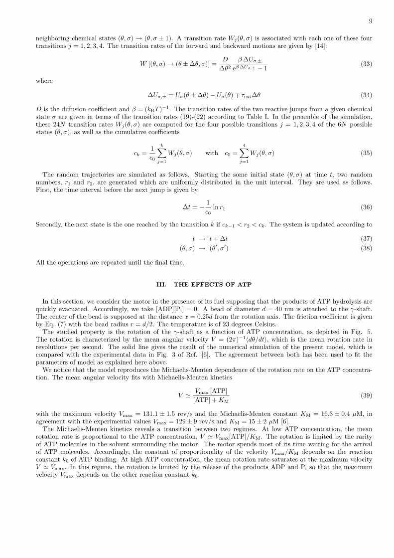
The studied property is the rotation of the γ-shaft as a function of ATP concentration, as depicted in Fig. 5.The rotation is characterized by the mean angular velocity V = (2π)−1〈dθ/dt〉, which is the mean rotation rate inrevolutions per second. The solid line gives the result of the numerical simulation of the present model, which iscompared with the experimental data in Fig. 3 of Ref. [6]. The agreement between both has been used to fit theparameters of model as explained here above.
We notice that the model reproduces the Michaelis-Menten dependence of the rotation rate on the ATP concentra-tion. The mean angular velocity fits with Michaelis-Menten kinetics
V ' Vmax [ATP][ATP] + KM
(39)
with the maximum velocity Vmax = 131.1 ± 1.5 rev/s and the Michaelis-Menten constant KM = 16.3 ± 0.4 µM, inagreement with the experimental values Vmax = 129± 9 rev/s and KM = 15± 2 µM [6].
The Michaelis-Menten kinetics reveals a transition between two regimes. At low ATP concentration, the meanrotation rate is proportional to the ATP concentration, V ' Vmax[ATP]/KM. The rotation is limited by the rarityof ATP molecules in the solvent surrounding the motor. The motor spends most of its time waiting for the arrivalof ATP molecules. Accordingly, the constant of proportionality of the velocity Vmax/KM depends on the reactionconstant k0 of ATP binding. At high ATP concentration, the mean rotation rate saturates at the maximum velocityV ' Vmax. In this regime, the rotation is limited by the release of the products ADP and Pi so that the maximumvelocity Vmax depends on the other reaction constant k0.
10
0.1
1
10
100
1000
10-8 10-7 10-6 10-5 10-4 10-3 10-2
th. exp.
rota
tio
n r
ate
(r
ev/s
)
[ATP] (M)
d = 40 nm
FIG. 5: Mean rotation rate of the γ-shaft of the F1 motor in revolutions per second, versus the ATP concentration [ATP] inmole per liter for [ADP][Pi] = 0. The diameter of the bead is d = 40 nm. The temperature is of 23 degrees Celsius. Theexternal torque is zero. The circles are the experimental data [6]. The solid line is the result of the present model.
0
1
2
3
4
5
6
7
8
0 0.02 0.04 0.06 0.08 0.1
rota
tio
n
(re
v)
time (s)
d = 40 nm [ATP] = 2 mM
[ATP] = 20 µM
[ATP] = 2 µM
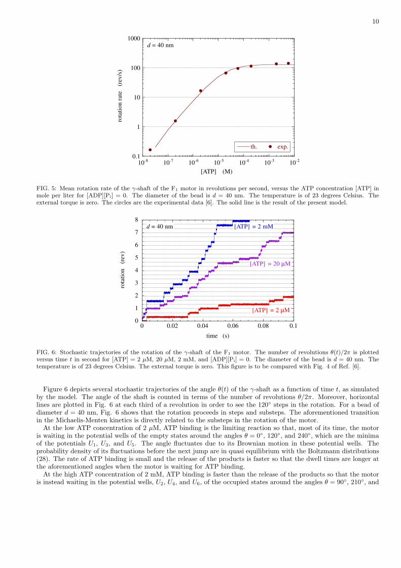
FIG. 6: Stochastic trajectories of the rotation of the γ-shaft of the F1 motor. The number of revolutions θ(t)/2π is plottedversus time t in second for [ATP] = 2 µM, 20 µM, 2 mM, and [ADP][Pi] = 0. The diameter of the bead is d = 40 nm. Thetemperature is of 23 degrees Celsius. The external torque is zero. This figure is to be compared with Fig. 4 of Ref. [6].
Figure 6 depicts several stochastic trajectories of the angle θ(t) of the γ-shaft as a function of time t, as simulatedby the model. The angle of the shaft is counted in terms of the number of revolutions θ/2π. Moreover, horizontallines are plotted in Fig. 6 at each third of a revolution in order to see the 120◦ steps in the rotation. For a bead ofdiameter d = 40 nm, Fig. 6 shows that the rotation proceeds in steps and substeps. The aforementioned transitionin the Michaelis-Menten kinetics is directly related to the substeps in the rotation of the motor.
At the low ATP concentration of 2 µM, ATP binding is the limiting reaction so that, most of its time, the motoris waiting in the potential wells of the empty states around the angles θ = 0◦, 120◦, and 240◦, which are the minimaof the potentials U1, U3, and U5. The angle fluctuates due to its Brownian motion in these potential wells. Theprobability density of its fluctuations before the next jump are in quasi equilibrium with the Boltzmann distributions(28). The rate of ATP binding is small and the release of the products is faster so that the dwell times are longer atthe aforementioned angles when the motor is waiting for ATP binding.
At the high ATP concentration of 2 mM, ATP binding is faster than the release of the products so that the motoris instead waiting in the potential wells, U2, U4, and U6, of the occupied states around the angles θ = 90◦, 210◦, and
11
330◦, as also seen in Fig. 6. In this case, the trajectories reveal the substeps of the release of the products becausetheir dwell times are longer than for ATP binding.
For the intermediate ATP concentration of 20 µM, all the substeps at the six angles are observed.These results show that the present model nicely reproduces the experimental features displayed in Fig. 4 of Ref.
[6].
IV. THE EFFECTS OF FRICTION AND TEMPERATURE
A. Friction
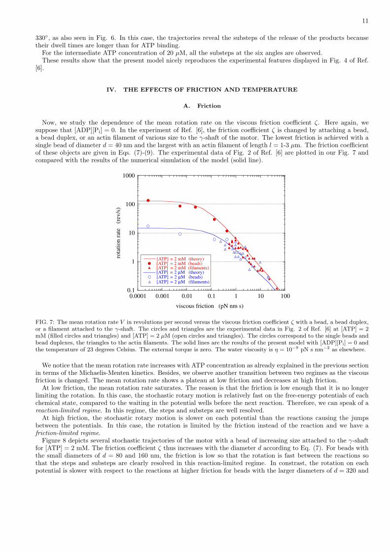
Now, we study the dependence of the mean rotation rate on the viscous friction coefficient ζ. Here again, wesuppose that [ADP][Pi] = 0. In the experiment of Ref. [6], the friction coefficient ζ is changed by attaching a bead,a bead duplex, or an actin filament of various size to the γ-shaft of the motor. The lowest friction is achieved with asingle bead of diameter d = 40 nm and the largest with an actin filament of length l = 1-3 µm. The friction coefficientof these objects are given in Eqs. (7)-(9). The experimental data of Fig. 2 of Ref. [6] are plotted in our Fig. 7 andcompared with the results of the numerical simulation of the model (solid line).
0.1
1
10
100
1000
0.0001 0.001 0.01 0.1 1 10 100
[ATP] = 2 mM (theory)[ATP] = 2 mM (beads)[ATP] = 2 mM (filaments)[ATP] = 2 µM (theory)[ATP] = 2 µM (beads)[ATP] = 2 µM (filaments)
rota
tio
n r
ate
(rev
/s)
viscous friction (pN nm s)
FIG. 7: The mean rotation rate V in revolutions per second versus the viscous friction coefficient ζ with a bead, a bead duplex,or a filament attached to the γ-shaft. The circles and triangles are the experimental data in Fig. 2 of Ref. [6] at [ATP] = 2mM (filled circles and triangles) and [ATP] = 2 µM (open circles and triangles). The circles correspond to the single beads andbead duplexes, the triangles to the actin filaments. The solid lines are the results of the present model with [ADP][Pi] = 0 andthe temperature of 23 degrees Celsius. The external torque is zero. The water viscosity is η = 10−9 pN s nm−2 as elsewhere.
We notice that the mean rotation rate increases with ATP concentration as already explained in the previous sectionin terms of the Michaelis-Menten kinetics. Besides, we observe another transition between two regimes as the viscousfriction is changed. The mean rotation rate shows a plateau at low friction and decreases at high friction.
At low friction, the mean rotation rate saturates. The reason is that the friction is low enough that it is no longerlimiting the rotation. In this case, the stochastic rotary motion is relatively fast on the free-energy potentials of eachchemical state, compared to the waiting in the potential wells before the next reaction. Therefore, we can speak of areaction-limited regime. In this regime, the steps and substeps are well resolved.
At high friction, the stochastic rotary motion is slower on each potential than the reactions causing the jumpsbetween the potentials. In this case, the rotation is limited by the friction instead of the reaction and we have afriction-limited regime.
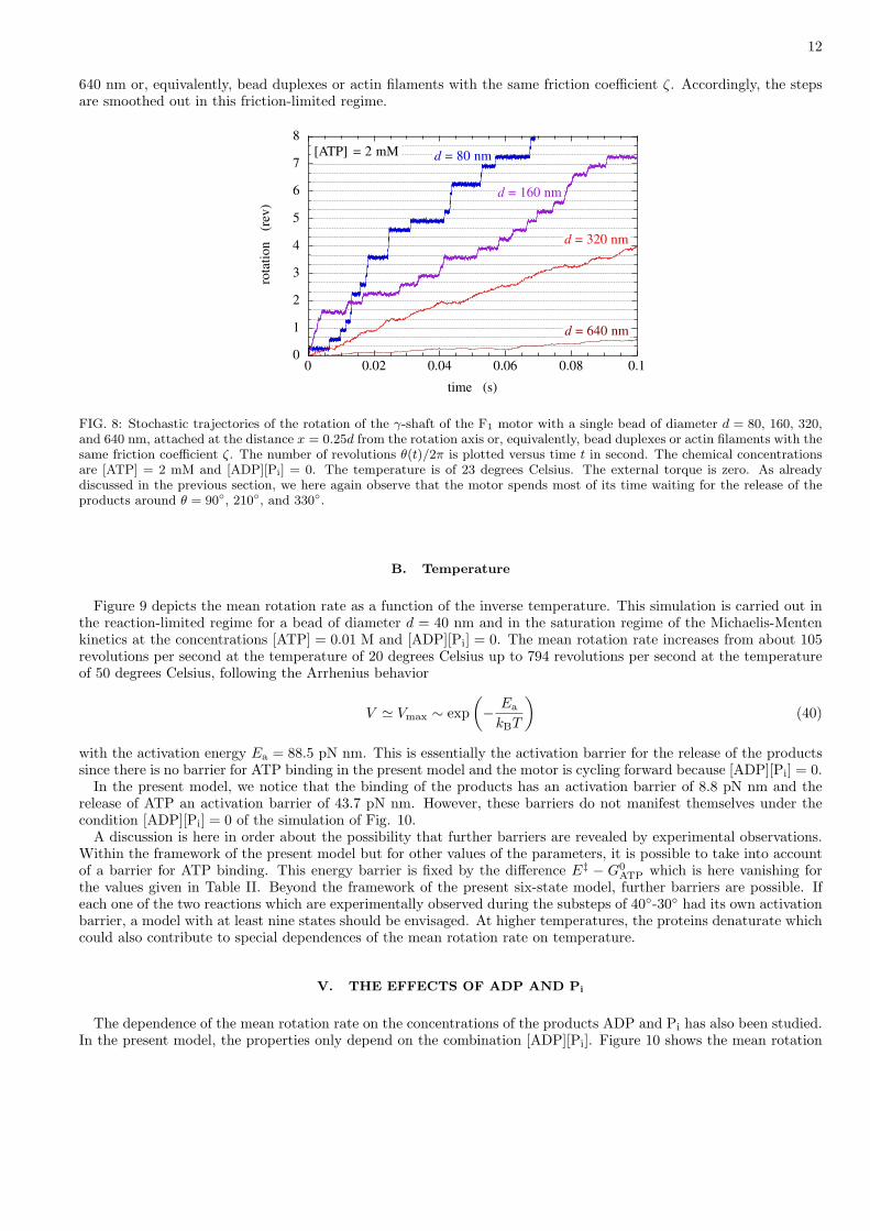
Figure 8 depicts several stochastic trajectories of the motor with a bead of increasing size attached to the γ-shaftfor [ATP] = 2 mM. The friction coefficient ζ thus increases with the diameter d according to Eq. (7). For beads withthe small diameters of d = 80 and 160 nm, the friction is low so that the rotation is fast between the reactions sothat the steps and substeps are clearly resolved in this reaction-limited regime. In constrast, the rotation on eachpotential is slower with respect to the reactions at higher friction for beads with the larger diameters of d = 320 and
12
640 nm or, equivalently, bead duplexes or actin filaments with the same friction coefficient ζ. Accordingly, the stepsare smoothed out in this friction-limited regime.
0
1
2
3
4
5
6
7
8
0 0.02 0.04 0.06 0.08 0.1
rota
tio
n
(re
v)
time (s)
[ATP] = 2 mM d = 80 nm
d = 160 nm
d = 320 nm
d = 640 nm
FIG. 8: Stochastic trajectories of the rotation of the γ-shaft of the F1 motor with a single bead of diameter d = 80, 160, 320,and 640 nm, attached at the distance x = 0.25d from the rotation axis or, equivalently, bead duplexes or actin filaments with thesame friction coefficient ζ. The number of revolutions θ(t)/2π is plotted versus time t in second. The chemical concentrationsare [ATP] = 2 mM and [ADP][Pi] = 0. The temperature is of 23 degrees Celsius. The external torque is zero. As alreadydiscussed in the previous section, we here again observe that the motor spends most of its time waiting for the release of theproducts around θ = 90◦, 210◦, and 330◦.
B. Temperature
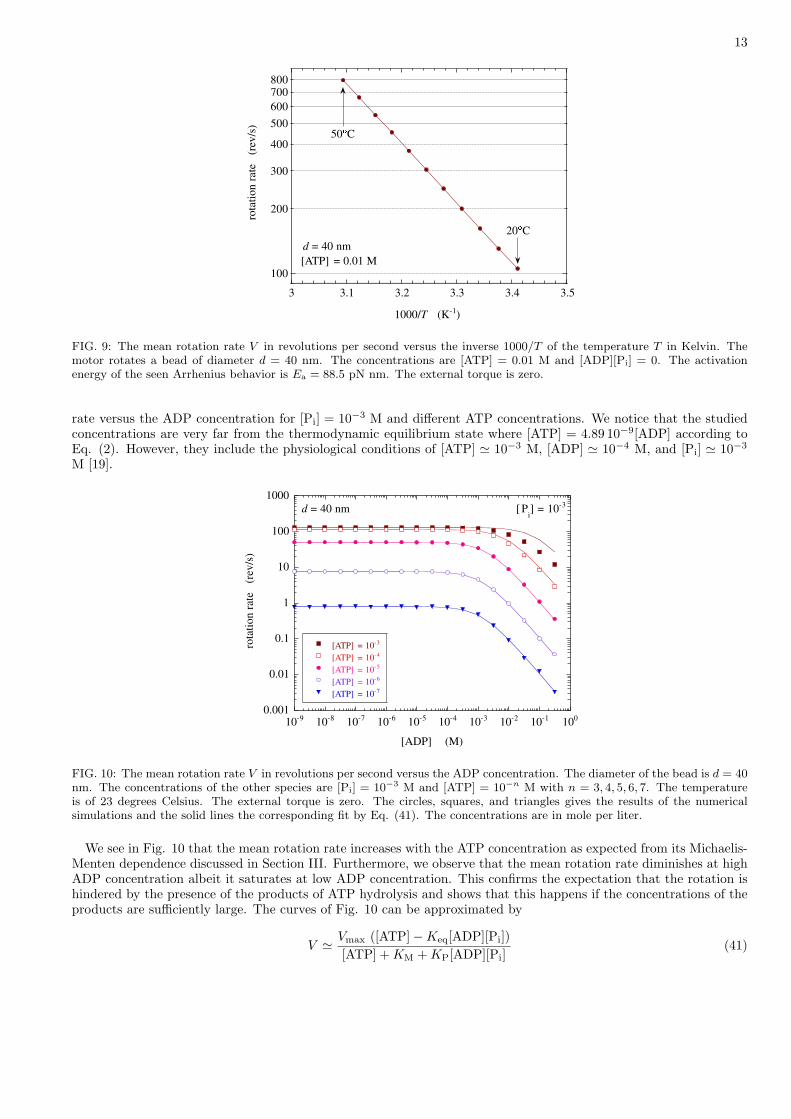
Figure 9 depicts the mean rotation rate as a function of the inverse temperature. This simulation is carried out inthe reaction-limited regime for a bead of diameter d = 40 nm and in the saturation regime of the Michaelis-Mentenkinetics at the concentrations [ATP] = 0.01 M and [ADP][Pi] = 0. The mean rotation rate increases from about 105revolutions per second at the temperature of 20 degrees Celsius up to 794 revolutions per second at the temperatureof 50 degrees Celsius, following the Arrhenius behavior
V ' Vmax ∼ exp(− Ea
kBT
)(40)
with the activation energy Ea = 88.5 pN nm. This is essentially the activation barrier for the release of the productssince there is no barrier for ATP binding in the present model and the motor is cycling forward because [ADP][Pi] = 0.
In the present model, we notice that the binding of the products has an activation barrier of 8.8 pN nm and therelease of ATP an activation barrier of 43.7 pN nm. However, these barriers do not manifest themselves under thecondition [ADP][Pi] = 0 of the simulation of Fig. 10.
A discussion is here in order about the possibility that further barriers are revealed by experimental observations.Within the framework of the present model but for other values of the parameters, it is possible to take into accountof a barrier for ATP binding. This energy barrier is fixed by the difference E‡ − G0
ATP which is here vanishing forthe values given in Table II. Beyond the framework of the present six-state model, further barriers are possible. Ifeach one of the two reactions which are experimentally observed during the substeps of 40◦-30◦ had its own activationbarrier, a model with at least nine states should be envisaged. At higher temperatures, the proteins denaturate whichcould also contribute to special dependences of the mean rotation rate on temperature.
V. THE EFFECTS OF ADP AND Pi
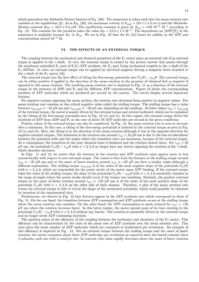
The dependence of the mean rotation rate on the concentrations of the products ADP and Pi has also been studied.In the present model, the properties only depend on the combination [ADP][Pi]. Figure 10 shows the mean rotation
13
100
200
300
400
500
600
700800
3 3.1 3.2 3.3 3.4 3.5
rota
tio
n r
ate
(
rev
/s)
1000/T (K-1
)
d = 40 nm
50�
C
20�
C
[ATP] = 0.01 M
FIG. 9: The mean rotation rate V in revolutions per second versus the inverse 1000/T of the temperature T in Kelvin. Themotor rotates a bead of diameter d = 40 nm. The concentrations are [ATP] = 0.01 M and [ADP][Pi] = 0. The activationenergy of the seen Arrhenius behavior is Ea = 88.5 pN nm. The external torque is zero.
rate versus the ADP concentration for [Pi] = 10−3 M and different ATP concentrations. We notice that the studiedconcentrations are very far from the thermodynamic equilibrium state where [ATP] = 4.89 10−9[ADP] according toEq. (2). However, they include the physiological conditions of [ATP] ' 10−3 M, [ADP] ' 10−4 M, and [Pi] ' 10−3
M [19].
0.001
0.01
0.1
1
10
100
1000
10-9
10-8
10-7
10-6
10-5
10-4
10-3
10-2
10-1
100
[ATP] = 10-3
[ATP] = 10-4
[ATP] = 10-5
[ATP] = 10-6
[ATP] = 10-7
rota
tio
n r
ate
(
rev
/s)
[ADP] (M)
d = 40 nm [ Pi] = 10
-3
FIG. 10: The mean rotation rate V in revolutions per second versus the ADP concentration. The diameter of the bead is d = 40nm. The concentrations of the other species are [Pi] = 10−3 M and [ATP] = 10−n M with n = 3, 4, 5, 6, 7. The temperatureis of 23 degrees Celsius. The external torque is zero. The circles, squares, and triangles gives the results of the numericalsimulations and the solid lines the corresponding fit by Eq. (41). The concentrations are in mole per liter.
We see in Fig. 10 that the mean rotation rate increases with the ATP concentration as expected from its Michaelis-Menten dependence discussed in Section III. Furthermore, we observe that the mean rotation rate diminishes at highADP concentration albeit it saturates at low ADP concentration. This confirms the expectation that the rotation ishindered by the presence of the products of ATP hydrolysis and shows that this happens if the concentrations of theproducts are sufficiently large. The curves of Fig. 10 can be approximated by
V ' Vmax ([ATP]−Keq[ADP][Pi])[ATP] + KM + KP[ADP][Pi]
(41)
14
which generalizes the Michaelis-Menten kinetics of Eq. (39). The numerator is taken such that the mean rotation ratevanishes at the equilibrium (2). As in Eq. (39), the maximum velocity is Vmax = 131.1± 1.5 rev/s and the Michaelis-Menten constant KM = 16.3 ± 0.4 µM. The equilibrium constant is given by Keq = 4.89 10−6 M−1 according toEq. (2). The constant for the products takes the value KP = 12.2 ± 1.5 M−1. The dependence on [ADP][Pi] in thenumerator is negligible because KP � Keq. We see in Fig. 10 that the fit (41) looses its validity as the ATP andconcentrations exceed 10−3 M.
VI. THE EFFECTS OF AN EXTERNAL TORQUE
The coupling between the mechanical and chemical properties of the F1 motor plays an essential role if an externaltorque is applied to the γ-shaft. In vivo, the external torque is caused by the proton current that passes throughthe membrane embedded Fo part of FoF1-ATP synthase, the Fo part being mechanical coupled to the γ-shaft of theF1-ATPase. In vitro, an external torque can be applied by electrical magnets driving a magnetic bead attached tothe γ-shaft of the F1 motor [16].
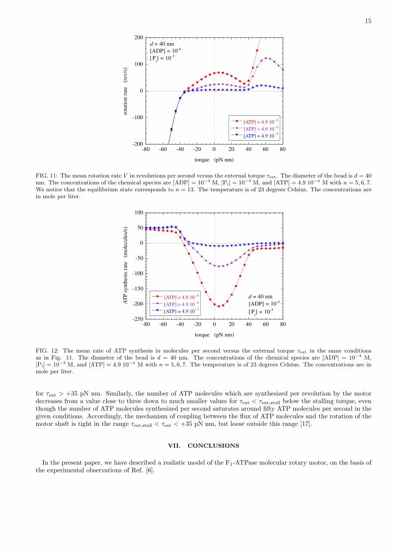
The external torque has the first effect of tilting the free-energy potentials into Uσ(θ)− τextθ. The external torquecan be either positive if applied in the direction of the mean rotation in the presence of chemical fuel or negative ifopposed to this mean rotation. The resulting mean rotation rate is depicted in Fig. 11 as a function of the externaltorque in the presence of ADP and Pi and for different ATP concentrations. Figure 12 shows the correspondingnumbers of ATP molecules which are produced per second by the system. The curves display several importantfeatures.
For negative torques opposing the mean motion, the rotation rate decreases from positive to negative values. Themean rotation rate vanishes at the critical negative value called the stalling torque. The stalling torque has a valuebetween τext,stall ' −25 pN nm and τext,stall ' −35 pN nm, depending on the condions. At lower values τext < τext,stall
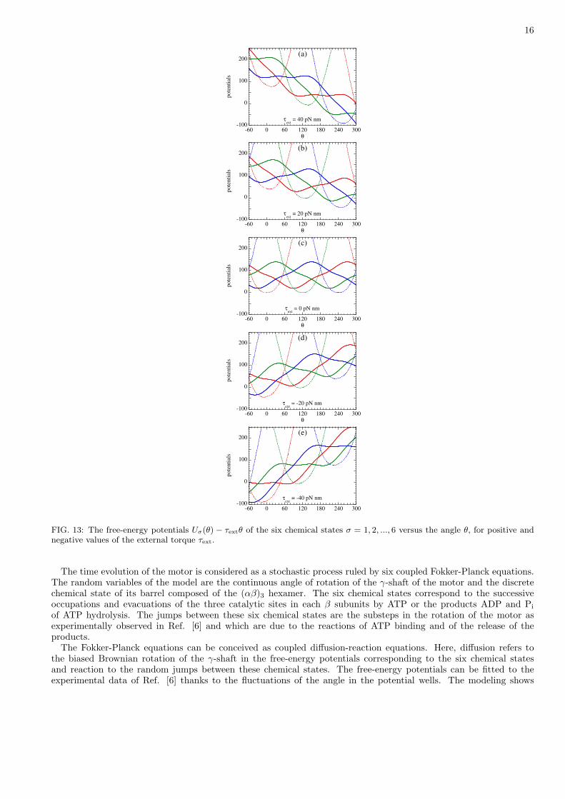
of the external torque, the motor is mainly driven by the external torque and rotates backward, which can be explainedby the tilting of the free-energy potentials seen in Fig. 13 (d) and (e). In this regime, the external torque drives thesynthesis of ATP from ADP and Pi at the rate of about 50 ATP molecules per second in the given conditions.
Positive values of the external torque can also be considered. In Fig. 12, the mean rotation rate is seen to increaseafter a minimum. In this case, a tilting of the free-energy potentials is induced by the external torque as seen in Fig.13 (a) and (b). Here, the tilting is in the direction of the mean rotation although it was in the opposite direction fornegative external torques. The minimum in the rotation rate around τext ' 35 pN nm is due to the loss of coincidencebetween the potential wells and the angles where the transition rates are maximum, because of the external torque.As a consequence, the transition to the next chemical state is hindered and the rotation slowed down. For τext > 35pN nm, the potentials Uσ(θ)− τextθ with σ = 2, 4, 6 no longer have any barrier opposing the rotation of the γ-shaft,which therefore increases.
In Figs. 11 and 12, we notice that the features in the rotation and ATP synthesis rates appear more or lesssymmetrically with respect to zero external torque. The reason is that both the features at the stalling torque aroundτext ' −35 pN nm and at the onset of faster rotation around τext ' +35 pN nm have a similar origin although adifferent explanation. The stalling torque τext,stall is of the order of the most negative slope of the potentials Uσ(θ)with σ = 2, 4, 6, which are responsible for the power stroke of the motor upon ATP binding. If the external torquetakes the value of the stalling torque, the slope of the potentials Uσ(θ)− τextθ with σ = 2, 4, 6 essentially vanishes inthe range of angles where the power stroke should occur if the torque was vanishing. Similarly, the positive externaltorque at the onset of faster rotation around τext ' +35 pN nm is of the order of the most positive slope of thepotentials Uσ(θ) with σ = 2, 4, 6 on the other side of their minima. Therefore, a plot of the mean rotation rateversus the external torque is able to reveal the shape of the mentioned potentials, which could possibly be obtainedby inversion of the experimental data.
Furthermore, we observe in Fig. 12 that features appear in the ATP synthesis rate which correspond to those ofFig. 11. On the one hand, the transition between ATP consumption and ATP synthesis occurs at the stalling torquewhere the mean rotation rate vanishes. On the other hand, the ATP consumption is much reduced for τext > +35pN nm where the rotation becomes faster. In this latter regime, the motor spends most of its time rotating in thepotentials Uσ(θ)− τextθ with σ = 2, 4, 6 without any barrier. The rotation is essentially driven by the external torqueand no longer needs ATP consuming reactions.
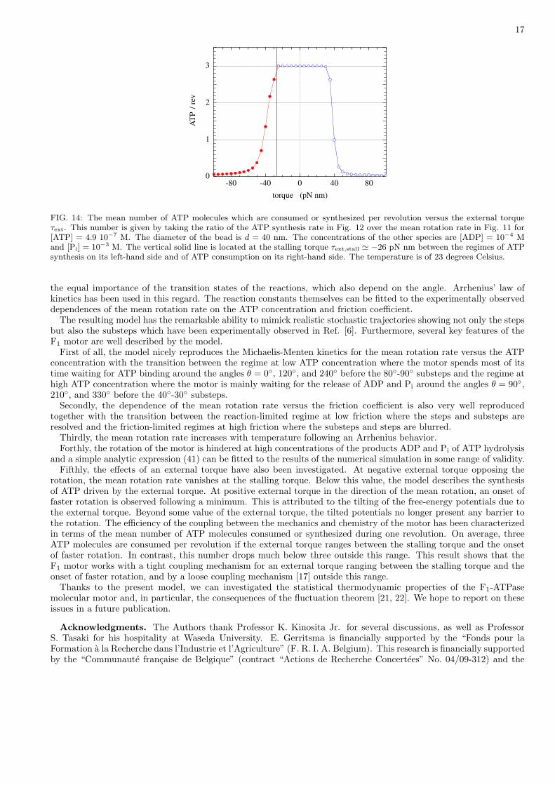
The question arises of the efficiency of the coupling between the mechanics and chemistry of the F1 motor. Thisefficiency can be characterized by the ratio of the mean rate of ATP synthesis over the mean rotation rate. Thisratio gives the mean number of ATP molecules which are consumed or synthesized per revolution. An example ofthis efficiency is depicted in Fig. 14. For an external torque between the stalling torque and the onset of fasterrotation, the motor consumes about three ATP molecules per revolution as expected since the barrel contains threeβ subunits, each one with a catalytic site. In contrast, this value rapidly decreases above the onset of faster rotation
15
-200
-100
0
100
200
-80 -60 -40 -20 0 20 40 60 80
[ATP] = 4.9 10 - 5
[ATP] = 4.9 10 - 6
[ATP] = 4.9 10 - 7
rota
tio
n r
ate
(r
ev/s
)
torque (pN nm)
d = 40 nm
[ Pi] = 10-3
[ADP] = 10-4
FIG. 11: The mean rotation rate V in revolutions per second versus the external torque τext. The diameter of the bead is d = 40nm. The concentrations of the chemical species are [ADP] = 10−4 M, [Pi] = 10−3 M, and [ATP] = 4.9 10−n M with n = 5, 6, 7.We notice that the equilibrium state corresponds to n = 13. The temperature is of 23 degrees Celsius. The concentrations arein mole per liter.
-250
-200
-150
-100
-50
0
50
100
-80 -60 -40 -20 0 20 40 60 80
[ATP] = 4.9 10 - 5
[ATP] = 4.9 10 - 6
[ATP] = 4.9 10 - 7
AT
P s
yn
thes
is r
ate
(m
ole
cule
s/s)
torque (pN nm)
d = 40 nm
[ Pi] = 10-3
[ADP] = 10-4
FIG. 12: The mean rate of ATP synthesis in molecules per second versus the external torque τext in the same conditionsas in Fig. 11. The diameter of the bead is d = 40 nm. The concentrations of the chemical species are [ADP] = 10−4 M,[Pi] = 10−3 M, and [ATP] = 4.9 10−n M with n = 5, 6, 7. The temperature is of 23 degrees Celsius. The concentrations are inmole per liter.
for τext > +35 pN nm. Similarly, the number of ATP molecules which are synthesized per revolution by the motordecreases from a value close to three down to much smaller values for τext < τext,stall below the stalling torque, eventhough the number of ATP molecules synthesized per second saturates around fifty ATP molecules per second in thegiven conditions. Accordingly, the mechanism of coupling between the flux of ATP molecules and the rotation of themotor shaft is tight in the range τext,stall < τext < +35 pN nm, but loose outside this range [17].
VII. CONCLUSIONS
In the present paper, we have described a realistic model of the F1-ATPase molecular rotary motor, on the basis ofthe experimental observations of Ref. [6].
16
-100
0
100
200
-60 0 60 120 180 240 300
po
ten
tial
s
θ
τext
= 40 pN nm
(a)
-100
0
100
200
-60 0 60 120 180 240 300p
ote
nti
als
θ
τext
= 20 pN nm
(b)
-100
0
100
200
-60 0 60 120 180 240 300
pote
nti
als
θ
τext
= 0 pN nm
(c)
-100
0
100
200
-60 0 60 120 180 240 300
pote
nti
als
θ
τext
= -20 pN nm
(d)
-100
0
100
200
-60 0 60 120 180 240 300
po
tenti
als
τext
= -40 pN nm
(e)
FIG. 13: The free-energy potentials Uσ(θ) − τextθ of the six chemical states σ = 1, 2, ..., 6 versus the angle θ, for positive andnegative values of the external torque τext.
The time evolution of the motor is considered as a stochastic process ruled by six coupled Fokker-Planck equations.The random variables of the model are the continuous angle of rotation of the γ-shaft of the motor and the discretechemical state of its barrel composed of the (αβ)3 hexamer. The six chemical states correspond to the successiveoccupations and evacuations of the three catalytic sites in each β subunits by ATP or the products ADP and Pi
of ATP hydrolysis. The jumps between these six chemical states are the substeps in the rotation of the motor asexperimentally observed in Ref. [6] and which are due to the reactions of ATP binding and of the release of theproducts.
The Fokker-Planck equations can be conceived as coupled diffusion-reaction equations. Here, diffusion refers tothe biased Brownian rotation of the γ-shaft in the free-energy potentials corresponding to the six chemical statesand reaction to the random jumps between these chemical states. The free-energy potentials can be fitted to theexperimental data of Ref. [6] thanks to the fluctuations of the angle in the potential wells. The modeling shows
17
0
1
2
3
-80 -40 0 40 80A
TP
/ r
evtorque (pN nm)
FIG. 14: The mean number of ATP molecules which are consumed or synthesized per revolution versus the external torqueτext. This number is given by taking the ratio of the ATP synthesis rate in Fig. 12 over the mean rotation rate in Fig. 11 for[ATP] = 4.9 10−7 M. The diameter of the bead is d = 40 nm. The concentrations of the other species are [ADP] = 10−4 Mand [Pi] = 10−3 M. The vertical solid line is located at the stalling torque τext,stall ' −26 pN nm between the regimes of ATPsynthesis on its left-hand side and of ATP consumption on its right-hand side. The temperature is of 23 degrees Celsius.
the equal importance of the transition states of the reactions, which also depend on the angle. Arrhenius’ law ofkinetics has been used in this regard. The reaction constants themselves can be fitted to the experimentally observeddependences of the mean rotation rate on the ATP concentration and friction coefficient.
The resulting model has the remarkable ability to mimick realistic stochastic trajectories showing not only the stepsbut also the substeps which have been experimentally observed in Ref. [6]. Furthermore, several key features of theF1 motor are well described by the model.
First of all, the model nicely reproduces the Michaelis-Menten kinetics for the mean rotation rate versus the ATPconcentration with the transition between the regime at low ATP concentration where the motor spends most of itstime waiting for ATP binding around the angles θ = 0◦, 120◦, and 240◦ before the 80◦-90◦ substeps and the regime athigh ATP concentration where the motor is mainly waiting for the release of ADP and Pi around the angles θ = 90◦,210◦, and 330◦ before the 40◦-30◦ substeps.
Secondly, the dependence of the mean rotation rate versus the friction coefficient is also very well reproducedtogether with the transition between the reaction-limited regime at low friction where the steps and substeps areresolved and the friction-limited regimes at high friction where the substeps and steps are blurred.
Thirdly, the mean rotation rate increases with temperature following an Arrhenius behavior.Forthly, the rotation of the motor is hindered at high concentrations of the products ADP and Pi of ATP hydrolysis
and a simple analytic expression (41) can be fitted to the results of the numerical simulation in some range of validity.Fifthly, the effects of an external torque have also been investigated. At negative external torque opposing the
rotation, the mean rotation rate vanishes at the stalling torque. Below this value, the model describes the synthesisof ATP driven by the external torque. At positive external torque in the direction of the mean rotation, an onset offaster rotation is observed following a minimum. This is attributed to the tilting of the free-energy potentials due tothe external torque. Beyond some value of the external torque, the tilted potentials no longer present any barrier tothe rotation. The efficiency of the coupling between the mechanics and chemistry of the motor has been characterizedin terms of the mean number of ATP molecules consumed or synthesized during one revolution. On average, threeATP molecules are consumed per revolution if the external torque ranges between the stalling torque and the onsetof faster rotation. In contrast, this number drops much below three outside this range. This result shows that theF1 motor works with a tight coupling mechanism for an external torque ranging between the stalling torque and theonset of faster rotation, and by a loose coupling mechanism [17] outside this range.
Thanks to the present model, we can investigated the statistical thermodynamic properties of the F1-ATPasemolecular motor and, in particular, the consequences of the fluctuation theorem [21, 22]. We hope to report on theseissues in a future publication.
Acknowledgments. The Authors thank Professor K. Kinosita Jr. for several discussions, as well as ProfessorS. Tasaki for his hospitality at Waseda University. E. Gerritsma is financially supported by the “Fonds pour laFormation a la Recherche dans l’Industrie et l’Agriculture” (F. R. I. A. Belgium). This research is financially supportedby the “Communaute francaise de Belgique” (contract “Actions de Recherche Concertees” No. 04/09-312) and the
18
National Fund for Scientific Research (F. N. R. S. Belgium, contract F. R. F. C. No. 2.4577.04).
[1] B. Alberts, D. Bray, A. Johnson, J. Lewis, M. Raff, K. Roberts, and P. Walter, Essential Cell Biology (Garland Publishing,New York, 1998).
[2] P. Boyer, Biochim. Biophys. Acta 1140, 215 (1993).[3] P. Mitchell, Nature 191, 144 (1961).[4] J. P. Abrahams, A. G. W. Leslie, R. Lutter, and J. E. Walker, Nature 370, 621 (1994).[5] H. Noji, R. Yasuda, M. Yoshida, and K. Kinosita Jr., Nature 386, 299 (1997).[6] R. Yasuda, H. Noji, M. Yoshida, K. Kinosita Jr., and H. Itoh, Nature 410, 898 (2001).[7] K. Shimabukuro, R. Yasuda, E. Muneyuki, K. Y. Hara, K. Kinosita Jr., and M. Yoshida, Proc. Natl. Acad. Sci. U. S. A.
100, 14731 (2003).[8] H. Wang and G. Oster, Nature 396, 279 (1998).[9] G. Oster and H. Wang, Biochim. Biophys. Acta 1458, 482 (2000).
[10] M. S. Liu, B. D. Todd, and R. J. Sadus, J. Chem. Phys. 118, 9890 (2003).[11] F. Julicher, A. Ajdari, and J. Prost, Rev. Mod. Phys. 69, 1269 (1997).[12] D. T. Gillespie, J. Comput. Phys. 22, 403 (1976).[13] D. T. Gillespie, J. Phys. Chem. 81, 2340 (1977).[14] H. Wang, C. S. Peskin, and T. C. Elston, J. Theor. Biol. 221, 491 (2003).[15] T. De Donder and P. Van Rysselberghe, Affinity (Stanford University Press, Menlo Park CA, 1936).[16] H. Itoh, A. Takahashi, K. Adachi, H. Noji, R. Yasuda, M. Yoshida, and K. Kinosita Jr., Nature 427, 465 (2004).[17] F. Oosawa and S. Hayashi, Adv. Biophys. 22, 151 (1986).[18] N. Sakaki, R. Shimo-Kon, K. Adachi, H. Itoh, S. Furuike, E. Muneyuki, M. Yoshida, and K. Kinosita Jr., Biophys. J. 88,
2047 (2005).[19] K. Kinosita Jr., K. Adachi, and H. Itoh, Annu. Rev. Biophys. Biomol. Struct. 33, 245 (2004).[20] A. J. Hunt, F. Gittes, and J. Howard, Biophys. J. 67, 766 (1994).[21] U. Seifert, Europhys. Lett. 70, 36 (2005).[22] D. Andrieux and P. Gaspard, Phys. Rev. E (2006).