Embed Size (px)
Citation preview
Journal of Materials Science Research; Vol. 5, No. 2; 2016 ISSN 1927-0585 E-ISSN 1927-0593
Published by Canadian Center of Science and Education
128
The Stress-Strain State of the Drill String at the Section of the Borehole with a Cavern
Ruslan Rachkevych1 & Iryna Rachkevych2 1 Ivano-Frankivsk National technical university of oil and gas, Ivano-Frankivsk, Ukraine 2 Ivano-Frankivsk National medical university, Ivano-Frankivsk, Ukraine Correspondence: Ruslan Rachkevych, Ivano-Frankivsk National technical university of oil and gas, Ivano-Frankivsk, 15 Karpatska Street, 76019, Ukraine. Tel: 38-0342-727-147. E-mail: [email protected] Received: January 29, 2016 Accepted: February 15, 2016 Online Published: March 31, 2016
doi:10.5539/jmsr.v5n2p128 URL: http://dx.doi.org/10.5539/jmsr.v5n2p128 Abstract This study analyses the stress-strain state of a drill string at the section of the borehole with a cavern/chute. The study was conducted to obtain analytical dependencies to determine normal bending stress in the cross section of the drill string and its downforces to the walls of the well. This will allow to compare these values with the critical ones, and draw conclusions about the possibility and duration of the drill string operation under these conditions. The study is based on modelling the drill string as a beam, which indicates longitudinal and transverse load and deforms in-plane. The formulas obtained to determine stresses and pressing forces apply to the following cases of the relative position of the drill string in a straight borehole and a curved borehole with a cavern/chute: a – the drill string touches only the bottom of the borehole; b – the drill string touches only the bottom of the borehole and the bottom of the cavern/chute; c – the drill string touches the top and the bottom of the borehole; d – the drill string touches the top and the bottom of the borehole and the cavern/chute. The calculations based on the dependencies obtained lead to the following conclusions: a – the cavern/chute in the inclined straight borehole causes bending stress value in the cross section of drill pipes proportional to the fatigue margin of the material; b – the cavern/chute in the curved borehole may increase normal bending stress in the cross section of the borehole up to five times. Keywords: drill string, stress-strain state, cavern, borehole 1. Introduction In practice, the shape of a borehole significantly differs from cylindrical. As a result of the drill string pressing to the walls of the well, and ravelling and erosion of softer rocks with the drilling fluid, chutes and caverns are formed. The process of formation of the latter is described in detail in the studies (Zhestovskiy, 1972; Peysikov, 1992; Frolov, Koshelev, & Alishanyan, 1970) therefore this article will not dwell upon it. On the other hand, chutes/caverns significantly complicate the working conditions of the drill string, which under their influence may incur additional transverse strain both in a straight and a curved borehole. This, in turn, may cause destruction of the drill pipes. Indeed, in "Ukrburhas" Drilling Department, for the period of 2007 to 2009, there were 73 complications and 14 accidents (Gryciv, 2012). 39 of them were due to the formation of chutes and violation of the integrity of the borehole walls, which is 45% of the total amount of complications and accidents. For example, on 4 April 2007, at the well No.300 of "Vesele" area, after lifting the drill string, it turned out that the assembly of the bottom of the string and drill pipes with a diameter of 127 mm and length of 38 m were left in the hole. The reason of disconnection of the drill string was it getting into the chute. On 27 November 2007, the reaming of the borehole No.4 of "Chkalove" area was conducted. When lifting the drill string, with the bit at a depth of 1340 m, there was friction due to it getting into the chute.
www.ccsenet.org/jmsr Journal of Materials Science Research Vol. 5, No. 2; 2016
129
A major accident occurred when drilling the third borehole of No.1 of "Komyshnia" oil and gas condensate field. The cause of the destruction of pipes was significant alternating stress in the cavernous section of the hole. After the directional survey of the well in the range of 4182–4205, caverns with a diameter of 500 mm were detected. Therefore, analytical methods that would allow to quantify the external load, strain, and stress arising in the drill string operated directly at the site of the chute/cavern are of practical interest. Indeed, Semenyuk (2002) suggests an analytical method of determining the orientation in space of chutes. Given the condition of equality of values of zenith and azimuth angles of the drill string axis and the curved section axis, the author obtained a formula to determine the direction and module of the vector of the downforce of pipes to the borehole walls.
γcos2 2222qPqP FFFFF ++= , (1)
1222
1
sin2
sin2
sin
sin2
sinsin
αβα
αβ
γΔ+Δ
Δ
= , (2)
where γ is the angle between the vector of downforce F and the vertical; αΔ , βΔ respectively is the change of zenith and azimuth angles of the beginning and end of the examined
interval;
1α is a zenith angle at the beginning of the examined interval;
PF is a downforce generated by axial force;
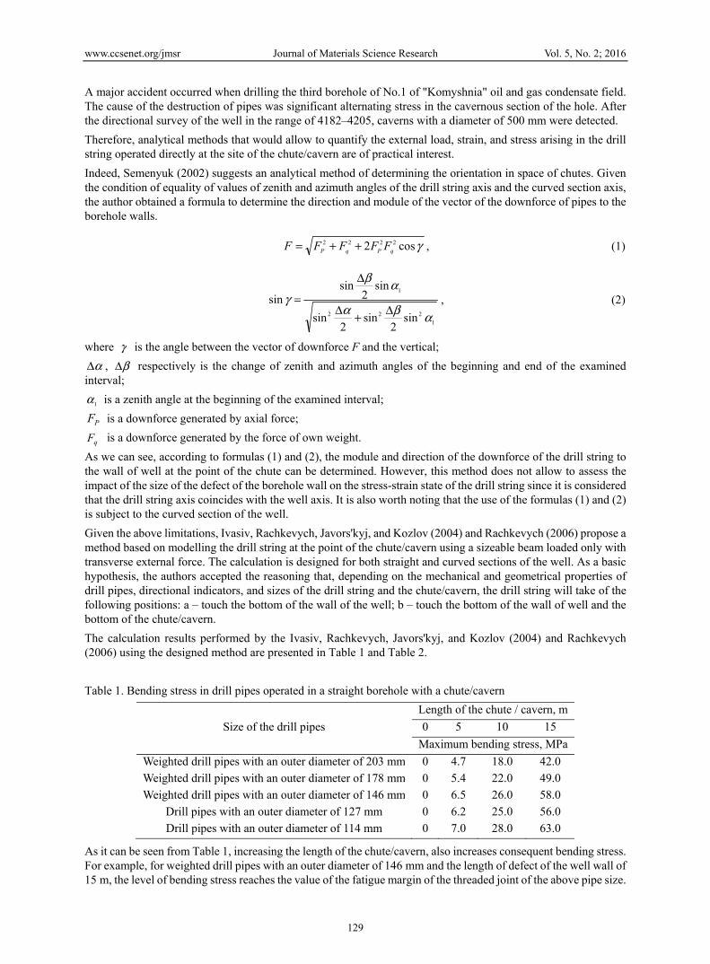
qF is a downforce generated by the force of own weight. As we can see, according to formulas (1) and (2), the module and direction of the downforce of the drill string to the wall of well at the point of the chute can be determined. However, this method does not allow to assess the impact of the size of the defect of the borehole wall on the stress-strain state of the drill string since it is considered that the drill string axis coincides with the well axis. It is also worth noting that the use of the formulas (1) and (2) is subject to the curved section of the well. Given the above limitations, Ivasiv, Rachkevych, Javors'kyj, and Kozlov (2004) and Rachkevych (2006) propose a method based on modelling the drill string at the point of the chute/cavern using a sizeable beam loaded only with transverse external force. The calculation is designed for both straight and curved sections of the well. As a basic hypothesis, the authors accepted the reasoning that, depending on the mechanical and geometrical properties of drill pipes, directional indicators, and sizes of the drill string and the chute/cavern, the drill string will take of the following positions: a – touch the bottom of the wall of the well; b – touch the bottom of the wall of well and the bottom of the chute/cavern. The calculation results performed by the Ivasiv, Rachkevych, Javors'kyj, and Kozlov (2004) and Rachkevych (2006) using the designed method are presented in Table 1 and Table 2. Table 1. Bending stress in drill pipes operated in a straight borehole with a chute/cavern
Size of the drill pipes Length of the chute / cavern, m 0 5 10 15
Maximum bending stress, MPa Weighted drill pipes with an outer diameter of 203 mm 0 4.7 18.0 42.0 Weighted drill pipes with an outer diameter of 178 mm 0 5.4 22.0 49.0 Weighted drill pipes with an outer diameter of 146 mm 0 6.5 26.0 58.0
Drill pipes with an outer diameter of 127 mm 0 6.2 25.0 56.0 Drill pipes with an outer diameter of 114 mm 0 7.0 28.0 63.0
As it can be seen from Table 1, increasing the length of the chute/cavern, also increases consequent bending stress. For example, for weighted drill pipes with an outer diameter of 146 mm and the length of defect of the well wall of 15 m, the level of bending stress reaches the value of the fatigue margin of the threaded joint of the above pipe size.
www.ccsenet.org/jmsr Journal of Materials Science Research Vol. 5, No. 2; 2016
130
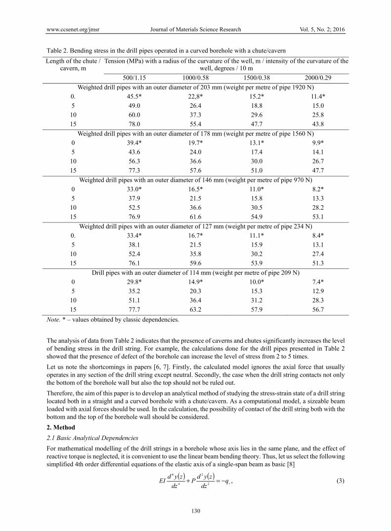
Table 2. Bending stress in the drill pipes operated in a curved borehole with a chute/cavern Length of the chute /
cavern, m Tension (MPa) with a radius of the curvature of the well, m / intensity of the curvature of the
well, degrees / 10 m 500/1.15 1000/0.58 1500/0.38 2000/0.29
Weighted drill pipes with an outer diameter of 203 mm (weight per metre of pipe 1920 N) 0. 45.5* 22,8* 15.2* 11.4*5 49.0 26.4 18.8 15.0
10 60.0 37.3 29.6 25.815 78.0 55.4 47.7 43.8
Weighted drill pipes with an outer diameter of 178 mm (weight per metre of pipe 1560 N) 0 39.4* 19.7* 13.1* 9.9*5 43.6 24.0 17.4 14.1
10 56.3 36.6 30.0 26.715 77.3 57.6 51.0 47.7
Weighted drill pipes with an outer diameter of 146 mm (weight per metre of pipe 970 N) 0 33.0* 16.5* 11.0* 8.2*5 37.9 21.5 15.8 13.3
10 52.5 36.6 30.5 28.215 76.9 61.6 54.9 53.1
Weighted drill pipes with an outer diameter of 127 mm (weight per metre of pipe 234 N) 0. 33.4* 16.7* 11.1* 8.4*5 38.1 21.5 15.9 13.1
10 52.4 35.8 30.2 27.415 76.1 59.6 53.9 51.3
Drill pipes with an outer diameter of 114 mm (weight per metre of pipe 209 N) 0 29.8* 14.9* 10.0* 7.4*5 35.2 20.3 15.3 12.9
10 51.1 36.4 31.2 28.315 77.7 63.2 57.9 56.7
Note. * – values obtained by classic dependencies. The analysis of data from Table 2 indicates that the presence of caverns and chutes significantly increases the level of bending stress in the drill string. For example, the calculations done for the drill pipes presented in Table 2 showed that the presence of defect of the borehole can increase the level of stress from 2 to 5 times. Let us note the shortcomings in papers [6, 7]. Firstly, the calculated model ignores the axial force that usually operates in any section of the drill string except neutral. Secondly, the case when the drill string contacts not only the bottom of the borehole wall but also the top should not be ruled out. Therefore, the aim of this paper is to develop an analytical method of studying the stress-strain state of a drill string located both in a straight and a curved borehole with a chute/cavern. As a computational model, a sizeable beam loaded with axial forces should be used. In the calculation, the possibility of contact of the drill string both with the bottom and the top of the borehole wall should be considered. 2. Method 2.1 Basic Analytical Dependencies For mathematical modelling of the drill strings in a borehole whose axis lies in the same plane, and the effect of reactive torque is neglected, it is convenient to use the linear beam bending theory. Thus, let us select the following simplified 4th order differential equations of the elastic axis of a single-span beam as basic [8]
( ) ( ) ,2
2
4
4
rqdz
zydPdz
zydEI −=+ (3)
www.ccsenet.org/jmsr Journal of Materials Science Research Vol. 5, No. 2; 2016
131
( ) ( ) ,2
2
4
4
rqdz
zydPdz
zydEI −=− (4)
where ЕI is beam bending stiffness; у(z) is a function of the elastic axis; P is axial force; qr is a radial component of weight per unit length. Formula (3) is used in the case of compression of the beam, and formula (4) in the case of tension. Solutions of the differential equations (3) and (4) will be as follows
( ) ,2
cossin 43
2
12 CzCSzqz
EIP
PEICz
EIP
PEICzy r ++−
−
−= (5)
( ) ,2
expexp 43
2
12 CzCSzqz
EIP
PEICz
EIP
PEICzy r +++
−+
= (6)
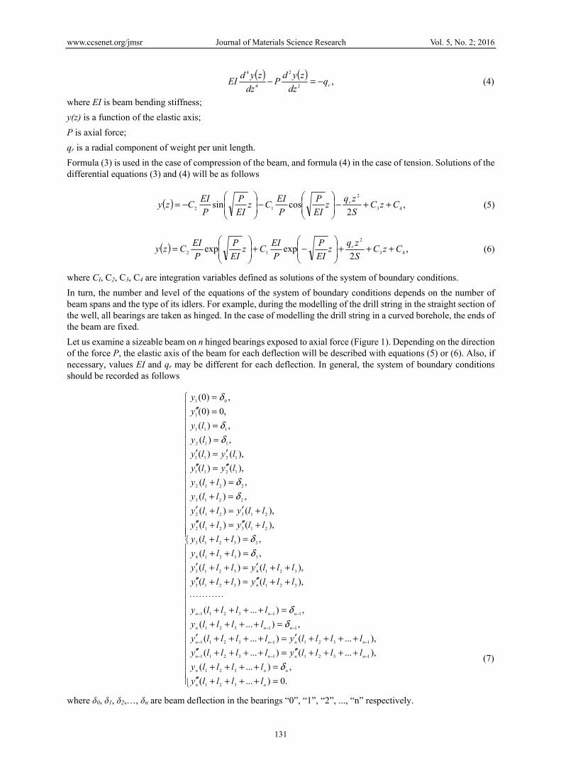
where СІ, С2, С3, С4 are integration variables defined as solutions of the system of boundary conditions. In turn, the number and level of the equations of the system of boundary conditions depends on the number of beam spans and the type of its idlers. For example, during the modelling of the drill string in the straight section of the well, all bearings are taken as hinged. In the case of modelling the drill string in a curved borehole, the ends of the beam are fixed. Let us examine a sizeable beam on п hinged bearings exposed to axial force (Figure 1). Depending on the direction of the force Р, the elastic axis of the beam for each deflection will be described with equations (5) or (6). Also, if necessary, values ЕІ and qr may be different for each deflection. In general, the system of boundary conditions should be recorded as follows
=++++′′=++++
++++′′=++++′′++++′=++++′
=++++=++++
⋅⋅⋅⋅⋅⋅⋅⋅⋅⋅⋅++′′=++′′++′=++′
=++=++
+′′=+′′+′=+′
=+=+′′=′′′=′
===′′=
−−−
−−−
−−
−−−
.0)...(,)...(
),...()...(),...()...(
,)...(,)...(
),()(),()(
,)(,)(
),()(),()(
,)(,)(
),()(),()(
,)(,)(
,0)0(,)0(
321
321
132113211
132113211
11321
113211
32143213
32143213
33214
33213
213212
213212
2213
2212
1211
1211
112
111
1
01
nn
nnn
nnnn
nnnn
nnn
nnn
llllylllly
llllyllllyllllylllly
llllylllly
lllylllylllyllly
lllyllly
llyllyllylly
llylly
lylylyly
lyly
yy
δ
δδ
δδ
δδ
δδ
δ
(7)
where δ0, δ1, δ2,…, δn are beam deflection in the bearings “0”, “1”, “2”, ..., “n” respectively.
www.ccsenet.org/jmsr Journal of Materials Science Research Vol. 5, No. 2; 2016
132
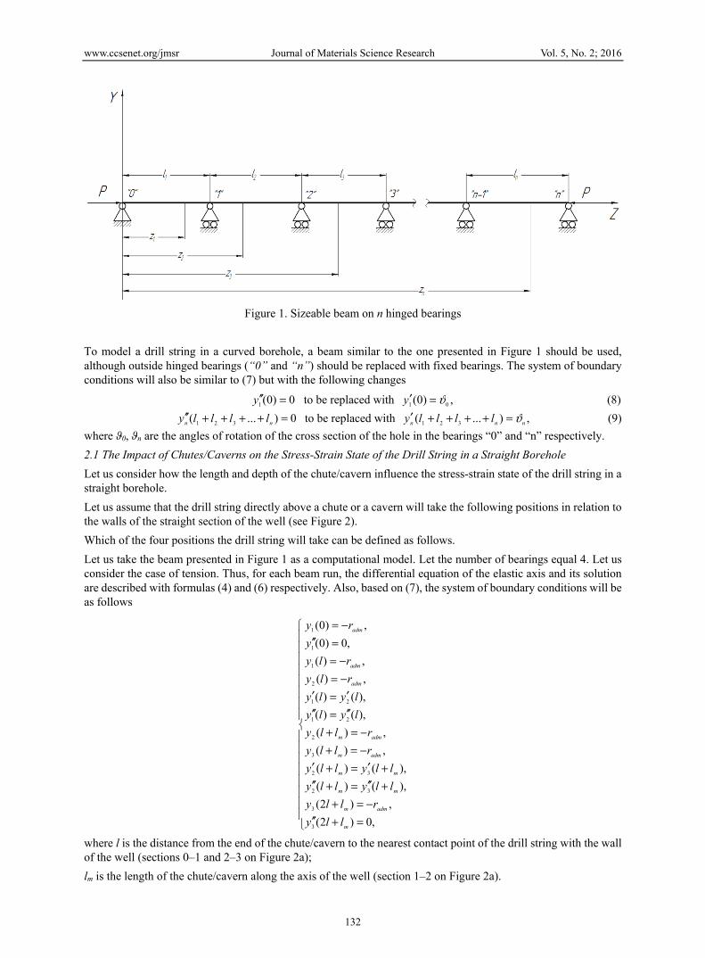
Figure 1. Sizeable beam on n hinged bearings
To model a drill string in a curved borehole, a beam similar to the one presented in Figure 1 should be used, although outside hinged bearings (“0” and “n”) should be replaced with fixed bearings. The system of boundary conditions will also be similar to (7) but with the following changes 0)0(1 =′′y to be replaced with ,)0( 01 ϑ=′y (8) 0)...( 321 =++++′′ nn lllly to be replaced with ,)...( 321 nnn lllly ϑ=++++′ (9) where ϑ0, ϑп are the angles of rotation of the cross section of the hole in the bearings “0” and “n” respectively. 2.1 The Impact of Chutes/Caverns on the Stress-Strain State of the Drill String in a Straight Borehole Let us consider how the length and depth of the chute/cavern influence the stress-strain state of the drill string in a straight borehole. Let us assume that the drill string directly above a chute or a cavern will take the following positions in relation to the walls of the straight section of the well (see Figure 2). Which of the four positions the drill string will take can be defined as follows. Let us take the beam presented in Figure 1 as a computational model. Let the number of bearings equal 4. Let us consider the case of tension. Thus, for each beam run, the differential equation of the elastic axis and its solution are described with formulas (4) and (6) respectively. Also, based on (7), the system of boundary conditions will be as follows
=+′′−=+
+′′=+′′+′=+′
−=+−=+
′′=′′′=′
−=−=
=′′−=
,0)2(,)2(
),()(),()(
,)(,)(
),()(),()(,)(,)(
,0)0(,)0(
3
3
32
32
3
2
21
21
2
1
1
1
m
admm
mm
mm
admm
admm
adm
adm
adm
llyrlly
llyllyllylly
rllyrlly
lylylyly
rlyrly
yry
where l is the distance from the end of the chute/cavern to the nearest contact point of the drill string with the wall of the well (sections 0–1 and 2–3 on Figure 2а); lт is the length of the chute/cavern along the axis of the well (section 1–2 on Figure 2а).
www.ccsenet.org/jmsr Journal of Materials Science Research Vol. 5, No. 2; 2016
133
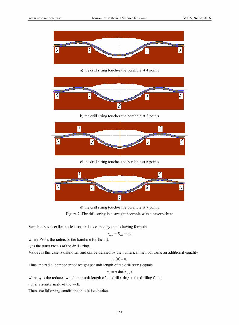
а) the drill string touches the borehole at 4 points
b) the drill string touches the borehole at 5 points
c) the drill string touches the borehole at 6 points
d) the drill string touches the borehole at 7 points
Figure 2. The drill string in a straight borehole with a cavern/chute Variable rаdт is called deflection, and is defined by the following formula ,cBHadm rRr −= where RВН is the radius of the borehole for the bit; rс is the outer radius of the drill string. Value l is this case is unknown, and can be defined by the numerical method, using an additional equality ( ) .001 =′y Thus, the radial component of weight per unit length of the drill string equals ( ),sin zenr qq α= where q is the reduced weight per unit length of the drill string in the drilling fluid; аzen is a zenith angle of the well. Then, the following conditions should be checked
www.ccsenet.org/jmsr Journal of Materials Science Research Vol. 5, No. 2; 2016
134
,max1 admry < (10)
,min2 cavry < (11)
where у1 тах is the maximum value of the function у1(z1) if the argument is changed from 0 to l; у2 min is the minimum value of the function у2(z2) if the argument is changed from l до lт; rcav is the deflection of the drill string above a chute or a cavern;
,ccavcav rRr −=
where Rcav is the radius of the borehole at the point of a chute/cavern. Meeting the conditions (10) and (11) proves that the drill string touches neither the top of the wall of the well nor the bottom of the chute/cavern. In this case, normal bending stress can be defined by the following formulas
,21
11 ydE c ′′=σ (12)
,21
22 ydE c ′′=σ (13)
dс is the outer diameter of the drill string. If the condition (10) is met, and (11) is not, the drill string touches the bottom of the chute/cavern. To analyse the stress-strain state, in this case, the response of the bottom of the chute/cavern to the drill string should be considered. Thus, for modelling, the beam from Figure 1 should be used but let us take the number of bearings as 5 (according to Figure 2b). As mentioned above, for each beam run, the differential equation of the elastic axis and its solution will take the form of (4) and (6) respectively. The system of boundary conditions, based on (7), will be as follows
=+′′−=+
+′′=+′′+′=+′
−=+−=+
+′′=+′′+′=+′
−=+−=+
′′=′′′=′
−=−=
=′′−=
.0)2(,)2(
),()(),()(
,)(,)(
),5,0()5,0(),5,0()5,0(
,)5,0(,)5,0(
),()(),()(
,)(,)(
,0)0(,)0(
4
4
43
43
4
3
32
32
3
2
21
21
2
1
1
1
m
admm
mm
mm
admm
admm
mm
mm
cavm
cavm
adm
adm
adm
llyrlly
llyllyllylly
rllyrlly
llyllyllylly
rllyrlly
lylylyly
rlyrly
yry
(14)
Dependencies to define normal bending stress will have the form of (12) and (13) but the variables of integration they include should be found using the system (14). Additionally, it is possible to determine the reaction of the wall of the chute/cavern to the drill string by the formula ( ).5,03 mcav llyEIR +′′′= (15) As it can be seen from Figure 2c, the case of strain of the drill string when there is contact with the top of the wall of the well but no contact with the bottom of a chute or a cavern is possible. This will be indicated by not meeting
www.ccsenet.org/jmsr Journal of Materials Science Research Vol. 5, No. 2; 2016
135
the condition (10) or meeting the condition (11). In this case, to model the drill string, a sizeable beam on 6 bearings is chosen (see Figure 2c). The general form of differential equations and their solutions remains unchanged ((4) and (6) respectively). However, to define the variables of integration, the following system of boundary conditions should be used
=++′′−=++
++′′=++′′++′=++′
−=++−=++
++′′=++′′++′=++′
−=++−=+++′′=+′′+′=+′
−=+−=+
′′=′′′=′
===′′
−=
.0)22(,)22(
),2()2(),2()2(
,)2(,)2(
),()(),()(
,)(,)(
),()(),()(
,)(,)(
),()(),()(,)(,)(
,0)0(,)0(
15
15
1514
1514
15
14
1413
1413
14
13
1312
1312
13
12
21
21
2
1
1
1
m
admm
mm
mm
admm
admm
mm
mm
admm
admm
adm
adm
adm
adm
adm
lllyrllly
lllylllylllyllly
rlllyrllly
lllylllylllyllly
rlllyrlllyllyllyllylly
rllyrlly
lylylyly
rlyrly
yry
(16)
In the system (16), l is the distance between the contact points of the drill string with the bottom and top of the borehole walls along the axis of the well (sections 0–1 and 4–5, Figure 2c), l1 is the distance from the end of a chute or a cavern to the contact point of the drill string with the top of the well wall (sections 1–2 and 3–4, Figure 2c). Given (16), normal bending stress is defined by the formulas (12) and (13), and the equality
.21
33 ydE c ′′=σ (17)
Let us define the reaction of the top of the wall of the well by the formula ( ).2 lyEIRvs ′′′= (18) Finally, there is an option when neither of the conditions (10) or (11) is met. This means that the drill string will touch both the top of the borehole and the bottom of the chute/cavern (Figure 2d). As we can see, to model the drill string, a sizeable beam on 7 bearings should be used. As in previous cases, the general form of differential equations and their solutions remains unchanged ((4) and (6) respectively). To calculate the value of the variables of integration, the following system of boundary conditions should be used
www.ccsenet.org/jmsr Journal of Materials Science Research Vol. 5, No. 2; 2016
136
=++′′−=++
++′′=++′′++′=++′
=++=++
++′′=++′′++′=++′
−=++−=++
++′′=++′′++′=++′
−=++−=++
+′′=+′′+′=+′
−=+−=+
′′=′′′=′
===′′
−=
.0)22(,)22(
),2()2(),2()2(
,)2(,)2(
),()(),()(
,)(,)(
),5,0()5,0(),5,0()5,0(
,)5,0(,)5,0(
),()(),()(
,)(,)(
),()(),()(,)(,)(
,0)0(,)0(
16
16
1615
1615
16
15
1514
1514
15
14
1413
1413
14
13
1312
1312
13
12
21
21
2
1
1
1
m
admm
mm
mm
admm
admm
mm
mm
admm
admm
mm
mm
cavm
cavm
adm
adm
adm
adm
adm
lllyrllly
lllylllylllyllly
rlllyrllly
lllylllylllyllly
rlllyrllly
lllylllylllyllly
rlllyrllly
llyllyllylly
rllyrlly
lylylyly
rlyrly
yry
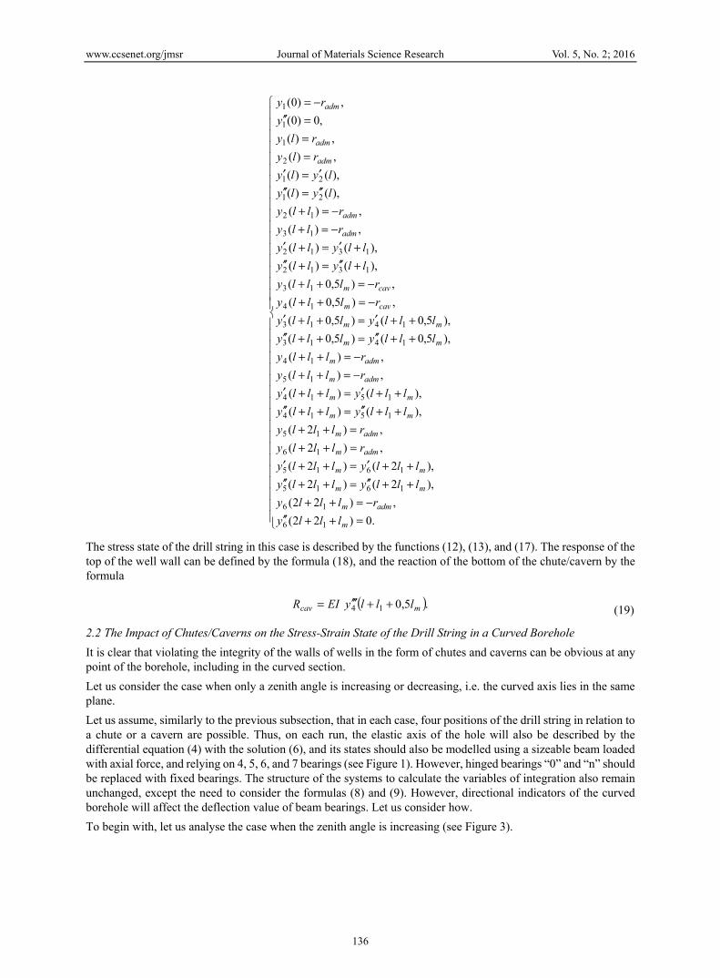
The stress state of the drill string in this case is described by the functions (12), (13), and (17). The response of the top of the well wall can be defined by the formula (18), and the reaction of the bottom of the chute/cavern by the formula
( ).5,014 mcav lllyEIR ++′′′= (19)
2.2 The Impact of Chutes/Caverns on the Stress-Strain State of the Drill String in a Curved Borehole It is clear that violating the integrity of the walls of wells in the form of chutes and caverns can be obvious at any point of the borehole, including in the curved section. Let us consider the case when only a zenith angle is increasing or decreasing, i.e. the curved axis lies in the same plane. Let us assume, similarly to the previous subsection, that in each case, four positions of the drill string in relation to a chute or a cavern are possible. Thus, on each run, the elastic axis of the hole will also be described by the differential equation (4) with the solution (6), and its states should also be modelled using a sizeable beam loaded with axial force, and relying on 4, 5, 6, and 7 bearings (see Figure 1). However, hinged bearings “0” and “n” should be replaced with fixed bearings. The structure of the systems to calculate the variables of integration also remain unchanged, except the need to consider the formulas (8) and (9). However, directional indicators of the curved borehole will affect the deflection value of beam bearings. Let us consider how. To begin with, let us analyse the case when the zenith angle is increasing (see Figure 3).
www.ccsenet.org/jmsr Journal of Materials Science Research Vol. 5, No. 2; 2016
137
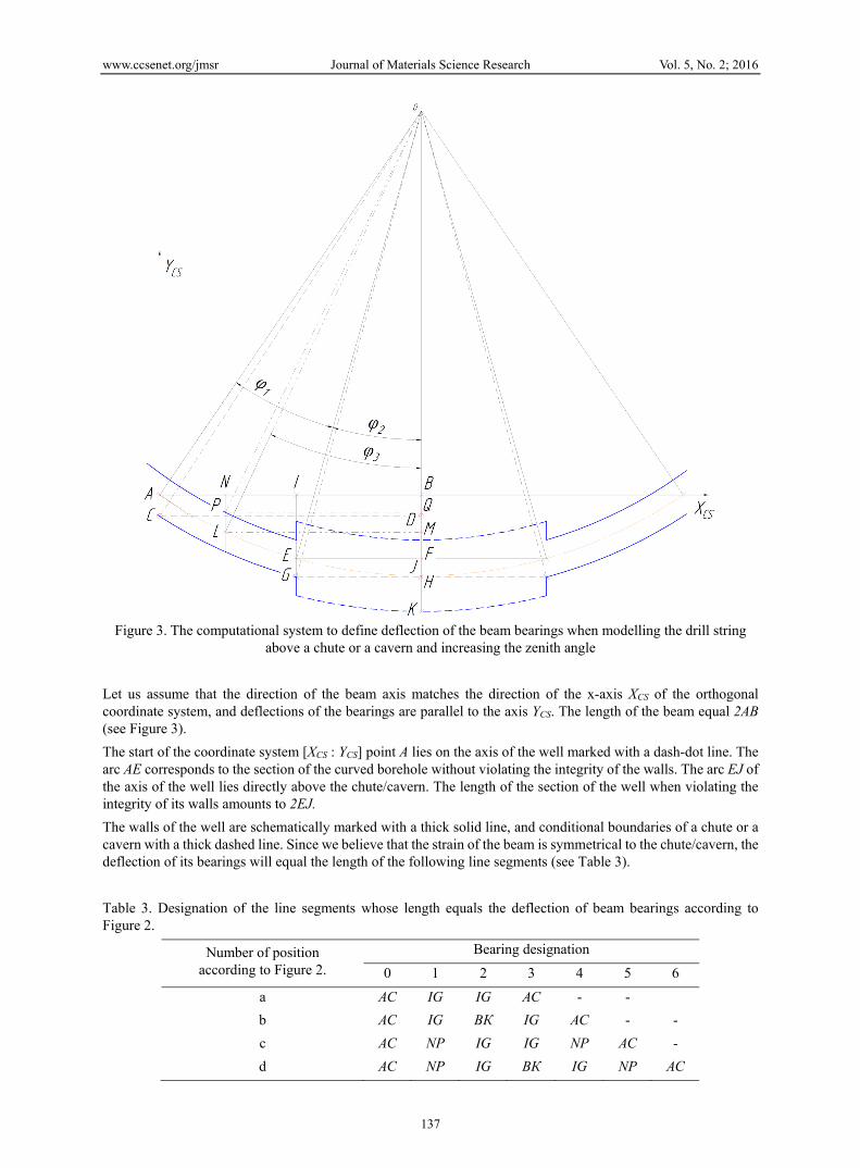
Figure 3. The computational system to define deflection of the beam bearings when modelling the drill string
above a chute or a cavern and increasing the zenith angle Let us assume that the direction of the beam axis matches the direction of the x-axis ХCS of the orthogonal coordinate system, and deflections of the bearings are parallel to the axis YCS. The length of the beam equal 2АВ (see Figure 3). The start of the coordinate system [ХCS : YCS] point A lies on the axis of the well marked with a dash-dot line. The arc AE corresponds to the section of the curved borehole without violating the integrity of the walls. The arc EJ of the axis of the well lies directly above the chute/cavern. The length of the section of the well when violating the integrity of its walls amounts to 2EJ. The walls of the well are schematically marked with a thick solid line, and conditional boundaries of a chute or a cavern with a thick dashed line. Since we believe that the strain of the beam is symmetrical to the chute/cavern, the deflection of its bearings will equal the length of the following line segments (see Table 3). Table 3. Designation of the line segments whose length equals the deflection of beam bearings according to Figure 2.
Number of position according to Figure 2.
Bearing designation 0 1 2 3 4 5 6
a АС IG IG АС - - b АС IG ВК IG АС - - c АС NP IG IG NP АС - d АС NP IG ВК IG NP АС
www.ccsenet.org/jmsr Journal of Materials Science Research Vol. 5, No. 2; 2016
138
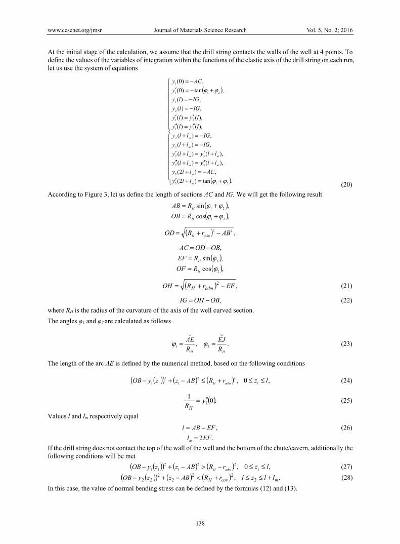
At the initial stage of the calculation, we assume that the drill string contacts the walls of the well at 4 points. To define the values of the variables of integration within the functions of the elastic axis of the drill string on each run, let us use the system of equations
( )
( )
+=+′−=+
+′′=+′′+′=+′
−=+−=+
′′=′′′=′
−=−=
+−=′−=
.tan)2(,)2(
),()(),()(
,)(,)(
),()(),()(,)(,)(
,tan)0(,)0(
213
3
32
32
3
2
21
21
2
1
211
1
ϕϕ
ϕϕ
m
m
mm
mm
m
m
llyAClly
llyllyllylly
IGllyIGlly
lylylyly
IGlyIGly
yACy
(20)
According to Figure 3, let us define the length of sections АС and IG. We will get the following result ( ),sin 21 ϕϕ += HRAB
( ),cos 21 ϕϕ += HROB
( ) ,22 ABrROD admH −+=
,OBODAC −= ( ),sin 2ϕHREF = ( ),cos 2ϕHROF =
( ) ,2 EFrROH admH −+= (21)
,OBOHIG −= (22) where RН is the radius of the curvature of the axis of the well curved section. The angles φ1 and φ2 are calculated as follows
,1HR
AE∪
=ϕ .2HR
EJ∪
=ϕ (23)
The length of the arc АЕ is defined by the numerical method, based on the following conditions
( )( ) ( ) ( ) ,221
211 admH rRABzzyOB +≤−+− ,0 1 lz ≤≤ (24)
( ).011y
RH′′= (25)
Values l and lm respectively equal
,EFABl −= (26) .2EFlm =
If the drill string does not contact the top of the wall of the well and the bottom of the chute/cavern, additionally the following conditions will be met ( )( ) ( ) ( ) ,22
12
11 admH rRABzzyOB −>−+− ,0 1 lz ≤≤ (27) ( )( ) ( ) ( ) ,22
22
22 cavH rRABzzyOB +<−+− .2 mllzl +≤≤ (28) In this case, the value of normal bending stress can be defined by the formulas (12) and (13).
www.ccsenet.org/jmsr Journal of Materials Science Research Vol. 5, No. 2; 2016
139
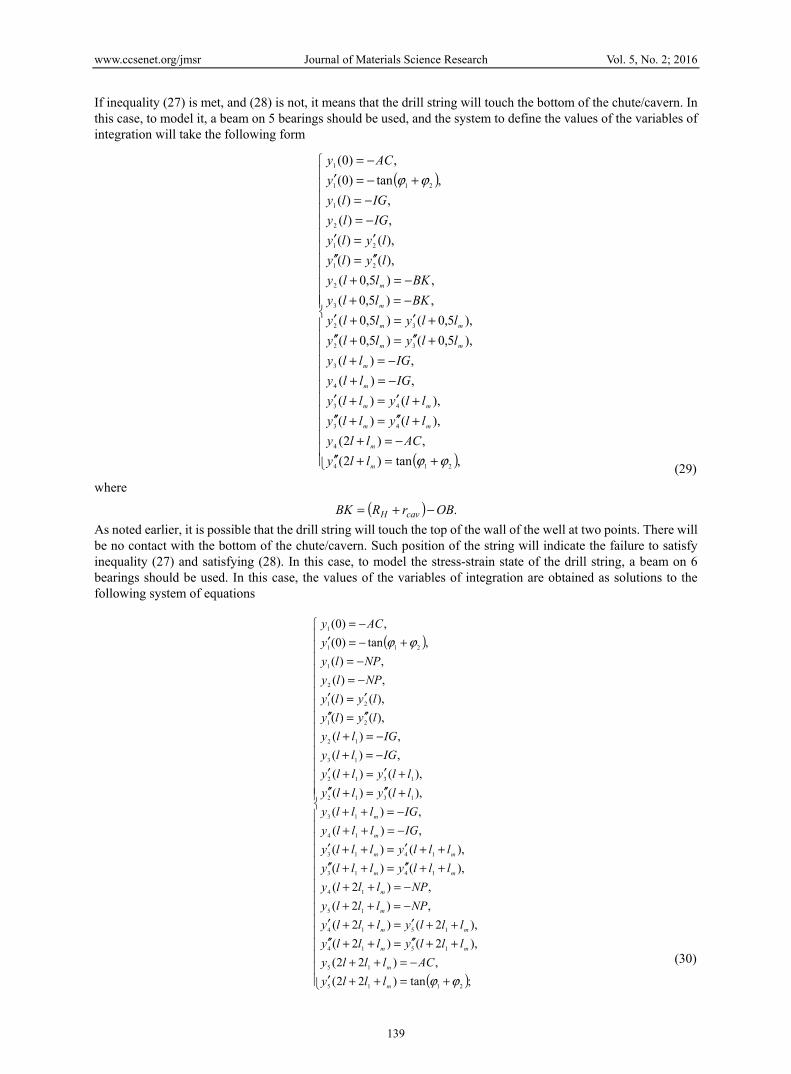
If inequality (27) is met, and (28) is not, it means that the drill string will touch the bottom of the chute/cavern. In this case, to model it, a beam on 5 bearings should be used, and the system to define the values of the variables of integration will take the following form
( )
( )
+=+′′−=+
+′′=+′′+′=+′
−=+−=+
+′′=+′′+′=+′
−=+−=+
′′=′′′=′
−=−=
+−=′−=
,tan)2(,)2(
),()(),()(
,)(,)(
),5,0()5,0(),5,0()5,0(
,)5,0(,)5,0(
),()(),()(,)(,)(
,tan)0(,)0(
214
4
43
43
4
3
32
32
3
2
21
21
2
1
211
1
ϕϕ
ϕϕ
m
m
mm
mm
m
m
mm
mm
m
m
llyAClly
llyllyllylly
IGllyIGlly
llyllyllylly
BKllyBKlly
lylylyly
IGlyIGly
yACy
(29)
where ( ) .OBrRBK cavH −+=
As noted earlier, it is possible that the drill string will touch the top of the wall of the well at two points. There will be no contact with the bottom of the chute/cavern. Such position of the string will indicate the failure to satisfy inequality (27) and satisfying (28). In this case, to model the stress-strain state of the drill string, a beam on 6 bearings should be used. In this case, the values of the variables of integration are obtained as solutions to the following system of equations
( )
( )
+=++′−=++
++′′=++′′++′=++′
−=++−=++
++′′=++′′++′=++′
−=++−=+++′′=+′′+′=+′
−=+−=+
′′=′′′=′
−=−=
+−=′−=
;tan)22(,)22(
),2()2(),2()2(
,)2(,)2(
),()(),()(
,)(,)(
),()(),()(
,)(,)(
),()(),()(,)(,)(
,tan)0(,)0(
2115
15
1514
1514
15
14
1413
1413
14
13
1312
1312
13
12
21
21
2
1
211
1
ϕϕ
ϕϕ
m
m
mm
mm
m
m
mm
mm
m
m
lllyACllly
lllylllylllyllly
NPlllyNPllly
lllylllylllyllly
IGlllyIGlllyllyllyllylly
IGllyIGlly
lylylyly
NPlyNPly
yACy
(30)
www.ccsenet.org/jmsr Journal of Materials Science Research Vol. 5, No. 2; 2016
140
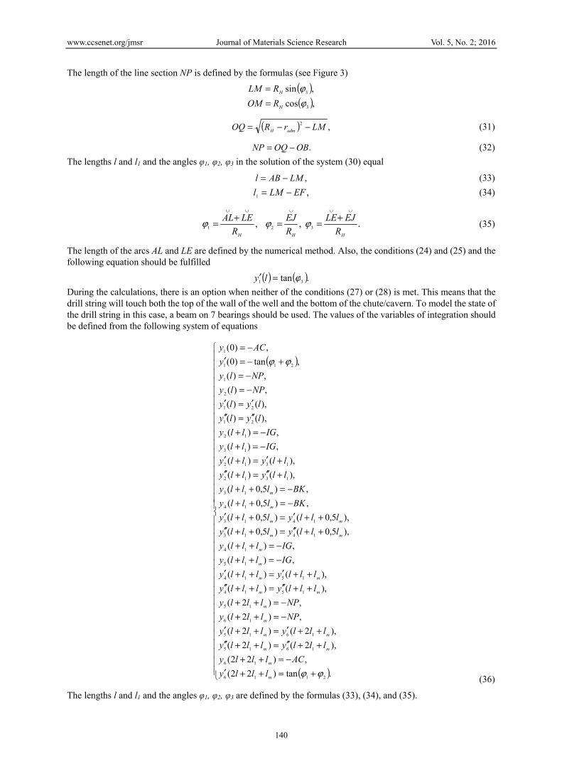
The length of the line section NP is defined by the formulas (see Figure 3) ( ),sin 3ϕHRLM = ( ),cos 3ϕHROM =
( ) ,2 LMrROQ admH −−= (31)
.OBOQNP −= (32) The lengths l and l1 and the angles φ1, φ2, φ3 in the solution of the system (30) equal
,LMABl −= (33) ,1 EFLMl −= (34)
,1HRLEAL
∪∪
+=ϕ ,2HR
EJ∪
=ϕ .3HREJLE
∪∪
+=ϕ (35)
The length of the arcs AL and LE are defined by the numerical method. Also, the conditions (24) and (25) and the following equation should be fulfilled
( ) ( ).tan 31 ϕ=′ ly During the calculations, there is an option when neither of the conditions (27) or (28) is met. This means that the drill string will touch both the top of the wall of the well and the bottom of the chute/cavern. To model the state of the drill string in this case, a beam on 7 bearings should be used. The values of the variables of integration should be defined from the following system of equations
( )
( )
+=++′−=++
++′′=++′′++′=++′
−=++−=++
++′′=++′′++′=++′
−=++−=++
++′′=++′′++′=++′
−=++−=++
+′′=+′′+′=+′
−=+−=+
′′=′′′=′
−=−=
+−=′−=
.tan)22(,)22(
),2()2(),2()2(
,)2(,)2(
),()(),()(
,)(,)(
),5,0()5,0(),5,0()5,0(
,)5,0(,)5,0(
),()(),()(
,)(,)(
),()(),()(,)(,)(
,tan)0(,)0(
2116
16
1615
1615
16
15
1514
1514
15
14
1413
1413
14
13
1312
1312
13
12
21
21
2
1
211
1
ϕϕ
ϕϕ
m
m
mm
mm
m
m
mm
mm
m
m
mm
mm
m
m
lllyACllly
lllylllylllyllly
NPlllyNPllly
lllylllylllyllly
IGlllyIGllly
lllylllylllyllly
BKlllyBKllly
llyllyllylly
IGllyIGlly
lylylyly
NPlyNPly
yACy
(36)
The lengths l and l1 and the angles φ1, φ2, φ3 are defined by the formulas (33), (34), and (35).
www.ccsenet.org/jmsr Journal of Materials Science Research Vol. 5, No. 2; 2016
141
Normal bending stress in any section of the drill string as well as the value of the response of the bottom of the chute/cavern and the top of the wall of the well can be defined by the formulas provided in Table 4. Table 4. Models of the drill string and corresponding numbers of the formulas to determine stress and reactions in a curved borehole
Drill string model Numbers of the formulas to determine stress
Numbers of the formulas to determine the reaction of the bottom of the chute / cavern
Numbers of the formulas to determine the reaction of the
top of the wall of the wellBeam on 4 bearings (12), (13) - - Beam on 5 bearings (12), (13) (15) - Beam on 6 bearings (12), (13), (17) - (18) Beam on 7 bearings (12), (13), (17) (19) (18)
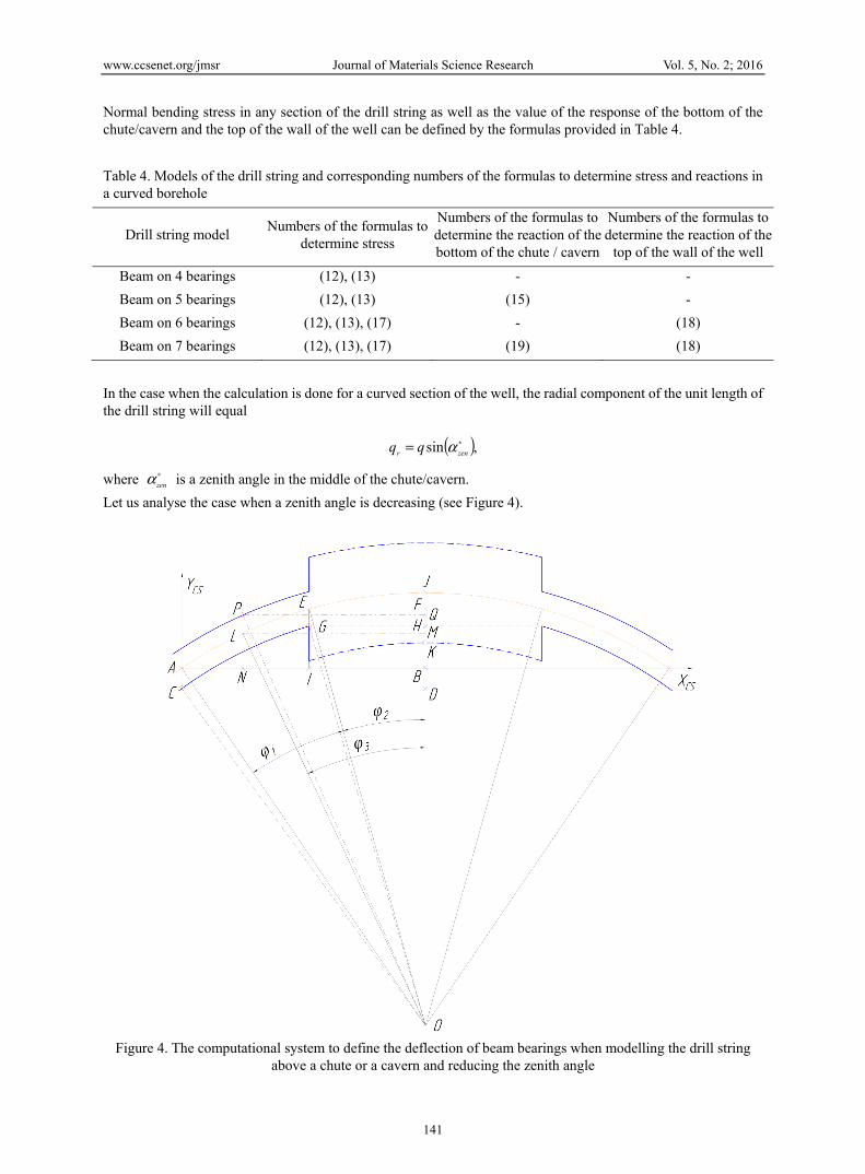
In the case when the calculation is done for a curved section of the well, the radial component of the unit length of the drill string will equal
( ),sin ∗= zenr qq α
where ∗zenα is a zenith angle in the middle of the chute/cavern.
Let us analyse the case when a zenith angle is decreasing (see Figure 4).
Figure 4. The computational system to define the deflection of beam bearings when modelling the drill string
above a chute or a cavern and reducing the zenith angle
www.ccsenet.org/jmsr Journal of Materials Science Research Vol. 5, No. 2; 2016
142
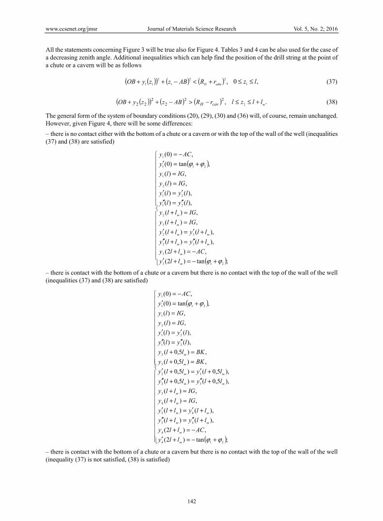
All the statements concerning Figure 3 will be true also for Figure 4. Tables 3 and 4 can be also used for the case of a decreasing zenith angle. Additional inequalities which can help find the position of the drill string at the point of a chute or a cavern will be as follows
( )( ) ( ) ( ) ,221
211 admH rRABzzyOB +<−++ ,0 1 lz ≤≤ (37)
( )( ) ( ) ( ) ,222
222 cavH rRABzzyOB −>−++ .2 mllzl +≤≤ (38)
The general form of the system of boundary conditions (20), (29), (30) and (36) will, of course, remain unchanged. However, given Figure 4, there will be some differences: – there is no contact either with the bottom of a chute or a cavern or with the top of the wall of the well (inequalities (37) and (38) are satisfied)
( )
( )
+−=+′−=+
+′′=+′′+′=+′
=+=+
′′=′′′=′
==
+=′−=
;tan)2(,)2(
),()(),()(
,)(,)(
),()(),()(
,)(,)(
,tan)0(,)0(
213
3
32
32
3
2
21
21
2
1
211
1
ϕϕ
ϕϕ
m
m
mm
mm
m
m
llyAClly
llyllyllylly
IGllyIGlly
lylylyly
IGlyIGly
yACy
– there is contact with the bottom of a chute or a cavern but there is no contact with the top of the wall of the well (inequalities (37) and (38) are satisfied)
( )
( )
+−=+′−=+
+′′=+′′+′=+′
=+=+
+′′=+′′+′=+′
=+=+
′′=′′′=′
==
+=′−=
;tan)2(,)2(
),()(),()(
,)(,)(
),5,0()5,0(),5,0()5,0(
,)5,0(,)5,0(
),()(),()(
,)(,)(
,tan)0(,)0(
214
4
43
43
4
3
32
32
3
2
21
21
2
1
211
1
ϕϕ
ϕϕ
m
m
mm
mm
m
m
mm
mm
m
m
llyAClly
llyllyllylly
IGllyIGlly
llyllyllylly
BKllyBKlly
lylylyly
IGlyIGly
yACy
– there is contact with the bottom of a chute or a cavern but there is no contact with the top of the wall of the well (inequality (37) is not satisfied, (38) is satisfied)
www.ccsenet.org/jmsr Journal of Materials Science Research Vol. 5, No. 2; 2016
143
( )
( )
+−=++′−=++
++′′=++′′++′=++′
=++=++
++′′=++′′++′=++′
=++=++
+′′=+′′+′=+′
=+=+′′=′′′=′
==
+=′−=
;tan)22(,)22(
),2()2(),2()2(
,)2(,)2(
),()(),()(
,)(,)(),()(),()(
,)(,)(
),()(),()(,)(,)(
,tan)0(,)0(
2115
15
1514
1514
15
14
1413
1413
14
13
1312
1312
13
12
21
21
2
1
211
1
ϕϕ
ϕϕ
m
m
mm
mm
m
m
mm
mm
m
m
lllyACllly
lllylllylllyllly
NPlllyNPllly
lllylllylllyllly
IGlllyIGllly
llyllyllylly
IGllyIGlly
lylylyly
NPlyNPly
yACy
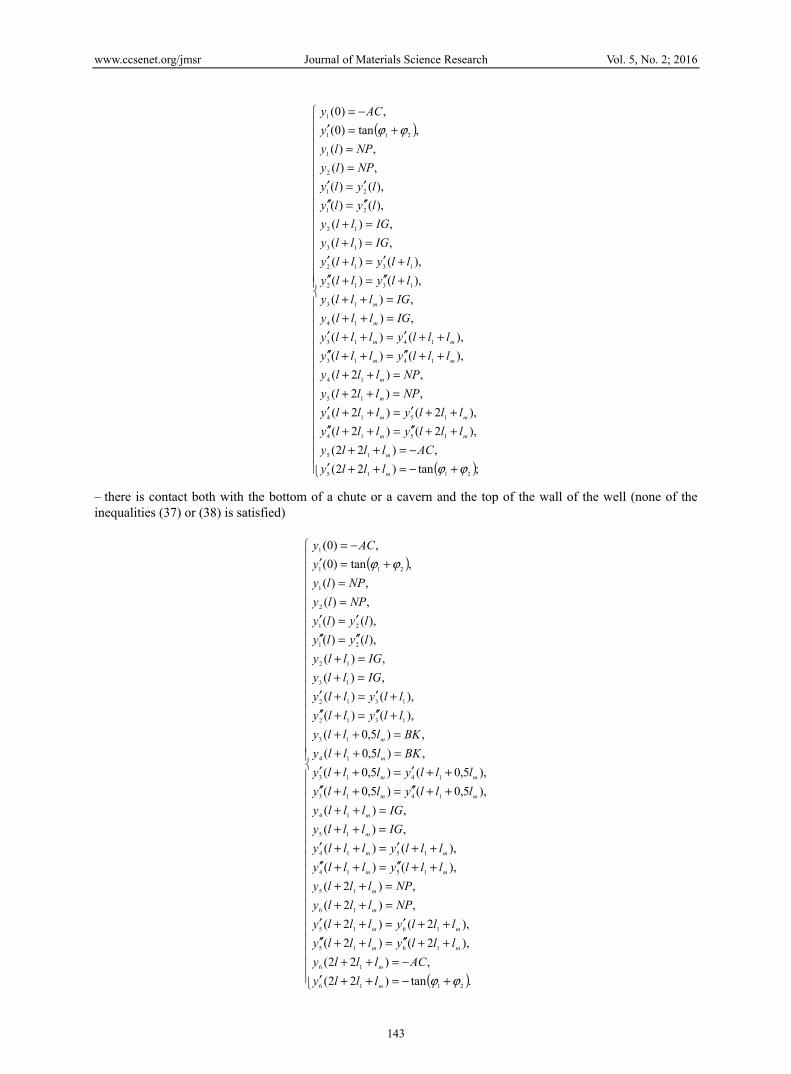
– there is contact both with the bottom of a chute or a cavern and the top of the wall of the well (none of the inequalities (37) or (38) is satisfied)
( )
( )
+−=++′−=++
++′′=++′′++′=++′
=++=++
++′′=++′′++′=++′
=++=++
++′′=++′′++′=++′
=++=++
+′′=+′′+′=+′
=+=+′′=′′′=′
==
+=′−=
.tan)22(,)22(
),2()2(),2()2(
,)2(,)2(
),()(),()(
,)(,)(
),5,0()5,0(),5,0()5,0(
,)5,0(,)5,0(
),()(),()(
,)(,)(
),()(),()(,)(,)(
,tan)0(,)0(
2116
16
1615
1615
16
15
1514
1514
15
14
1413
1413
14
13
1312
1312
13
12
21
21
2
1
211
1
ϕϕ
ϕϕ
m
m
mm
mm
m
m
mm
mm
m
m
mm
mm
m
m
lllyACllly
lllylllylllyllly
NPlllyNPllly
lllylllylllyllly
IGlllyIGllly
lllylllylllyllly
BKlllyBKllly
llyllyllylly
IGllyIGlly
lylylyly
NPlyNPly
yACy
www.ccsenet.org/jmsr Journal of Materials Science Research Vol. 5, No. 2; 2016
144
In case of a decreasing zenith angle (please see Figure 4), the length of the line sections АС and ВК are defined by the following equations
,ODOBAC −= ( ) .OBrRBK cavH −−=
Values IG, NP, l, l1, φ1, φ2, φ3 can be calculated by the formulas (22), (32), and (26), or (33), (34), (23), and (35). However, in the calculation algorithms, equality (21) should be replaced with
( ) ,2 EFrROH admH −−=
and equality (31) with
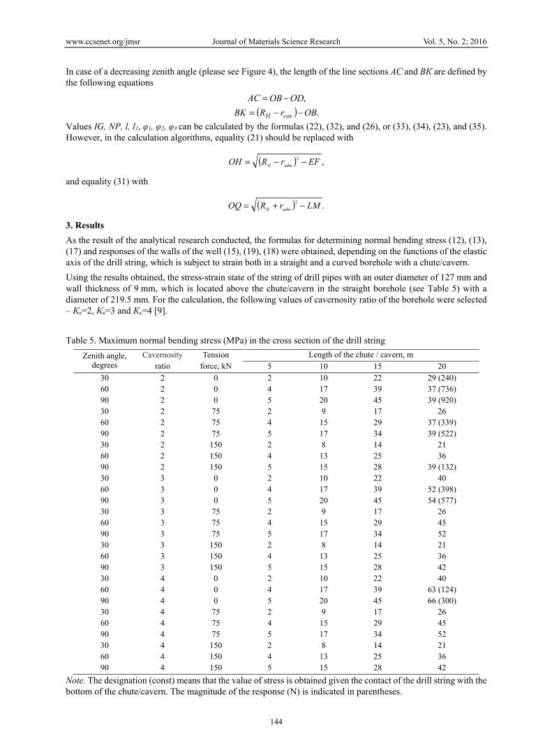
( ) .2 LMrROQ admH −+= 3. Results As the result of the analytical research conducted, the formulas for determining normal bending stress (12), (13), (17) and responses of the walls of the well (15), (19), (18) were obtained, depending on the functions of the elastic axis of the drill string, which is subject to strain both in a straight and a curved borehole with a chute/cavern. Using the results obtained, the stress-strain state of the string of drill pipes with an outer diameter of 127 mm and wall thickness of 9 mm, which is located above the chute/cavern in the straight borehole (see Table 5) with a diameter of 219.5 mm. For the calculation, the following values of cavernosity ratio of the borehole were selected – Кк=2, Кк=3 and Кк=4 [9]. Table 5. Maximum normal bending stress (MPa) in the cross section of the drill string
Zenith angle, degrees
Cavernosity ratio
Tension force, kN
Length of the chute / cavern, m 5 10 15 20
30 2 0 2 10 22 29 (240) 60 2 0 4 17 39 37 (736) 90 2 0 5 20 45 39 (920) 30 2 75 2 9 17 26 60 2 75 4 15 29 37 (339) 90 2 75 5 17 34 39 (522) 30 2 150 2 8 14 21 60 2 150 4 13 25 36 90 2 150 5 15 28 39 (132) 30 3 0 2 10 22 40 60 3 0 4 17 39 52 (398) 90 3 0 5 20 45 54 (577) 30 3 75 2 9 17 26 60 3 75 4 15 29 45 90 3 75 5 17 34 52 30 3 150 2 8 14 21 60 3 150 4 13 25 36 90 3 150 5 15 28 42 30 4 0 2 10 22 40 60 4 0 4 17 39 63 (124) 90 4 0 5 20 45 66 (300) 30 4 75 2 9 17 26 60 4 75 4 15 29 45 90 4 75 5 17 34 52 30 4 150 2 8 14 21 60 4 150 4 13 25 36 90 4 150 5 15 28 42
Note. The designation (const) means that the value of stress is obtained given the contact of the drill string with the bottom of the chute/cavern. The magnitude of the response (N) is indicated in parentheses.
www.ccsenet.org/jmsr Journal of Materials Science Research Vol. 5, No. 2; 2016
145
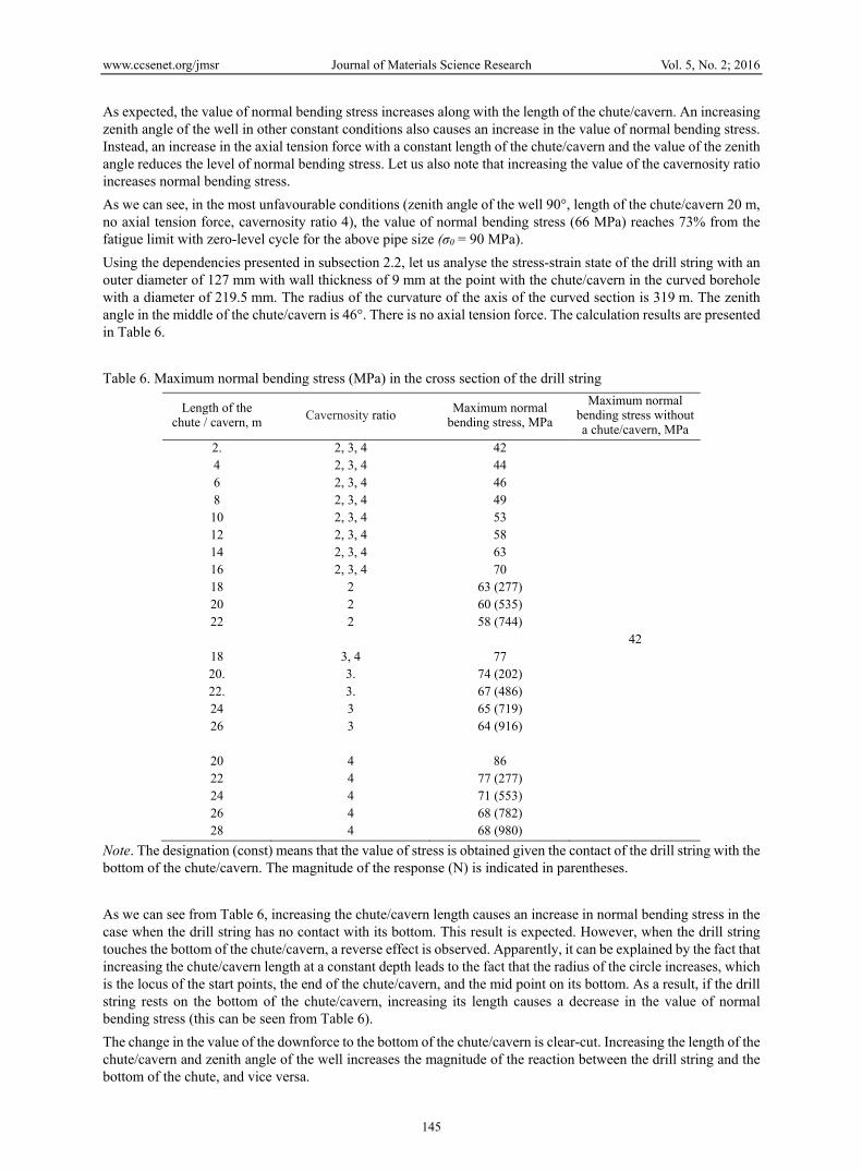
As expected, the value of normal bending stress increases along with the length of the chute/cavern. An increasing zenith angle of the well in other constant conditions also causes an increase in the value of normal bending stress. Instead, an increase in the axial tension force with a constant length of the chute/cavern and the value of the zenith angle reduces the level of normal bending stress. Let us also note that increasing the value of the cavernosity ratio increases normal bending stress. As we can see, in the most unfavourable conditions (zenith angle of the well 90°, length of the chute/cavern 20 m, no axial tension force, cavernosity ratio 4), the value of normal bending stress (66 MPa) reaches 73% from the fatigue limit with zero-level cycle for the above pipe size (σ0 = 90 MPa). Using the dependencies presented in subsection 2.2, let us analyse the stress-strain state of the drill string with an outer diameter of 127 mm with wall thickness of 9 mm at the point with the chute/cavern in the curved borehole with a diameter of 219.5 mm. The radius of the curvature of the axis of the curved section is 319 m. The zenith angle in the middle of the chute/cavern is 46°. There is no axial tension force. The calculation results are presented in Table 6. Table 6. Maximum normal bending stress (MPa) in the cross section of the drill string
Length of the chute / cavern, m Cavernosity ratio Maximum normal
bending stress, MPa Maximum normal
bending stress without a chute/cavern, MPa
2. 2, 3, 4 42 4 2, 3, 4 44 6 2, 3, 4 46 8 2, 3, 4 49 10 2, 3, 4 53 12 2, 3, 4 58 14 2, 3, 4 63 16 2, 3, 4 70 18 2 63 (277) 20 2 60 (535) 22 2 58 (744) 42
18 3, 4 77 20. 3. 74 (202) 22. 3. 67 (486) 24 3 65 (719) 26 3 64 (916)
20 4 86 22 4 77 (277) 24 4 71 (553) 26 4 68 (782) 28 4 68 (980)
Note. The designation (const) means that the value of stress is obtained given the contact of the drill string with the bottom of the chute/cavern. The magnitude of the response (N) is indicated in parentheses. As we can see from Table 6, increasing the chute/cavern length causes an increase in normal bending stress in the case when the drill string has no contact with its bottom. This result is expected. However, when the drill string touches the bottom of the chute/cavern, a reverse effect is observed. Apparently, it can be explained by the fact that increasing the chute/cavern length at a constant depth leads to the fact that the radius of the circle increases, which is the locus of the start points, the end of the chute/cavern, and the mid point on its bottom. As a result, if the drill string rests on the bottom of the chute/cavern, increasing its length causes a decrease in the value of normal bending stress (this can be seen from Table 6). The change in the value of the downforce to the bottom of the chute/cavern is clear-cut. Increasing the length of the chute/cavern and zenith angle of the well increases the magnitude of the reaction between the drill string and the bottom of the chute, and vice versa.
www.ccsenet.org/jmsr Journal of Materials Science Research Vol. 5, No. 2; 2016
146
Let us slightly change the initial data. Let the nominal diameter of the well equal 190.5 mm. Geometrical parameters of the well at the point of the chute are as follows – diameter 2000 mm; length 32 m; zenith angle 70°. According to inequalities (27) and (28), the drill string will touch the top of the wall of the well. The maximum bending stress that will occur equals 186 MPa. As we can see, this value is approximately twice as high as the fatigue limit of the drill pipes. The downforce of the drill string to the top of the wall of the well equals 2445 N. If the diameter of the well at the point of the chute/cavern equalled 1800 mm, the drill string would additionally contact the bottom of the chute/cavern. In this case, the maximum value of normal bending stress will be 176 MPa. The downforce of the drill string to the bottom of the chute/cavern will be 112 N, and the reaction between the string and the top of the wall of the well will be 2205 N. 4. Conclusion Summarising the results of the calculations from Tables 5 and 6, it should be noted that the proposed calculated dependencies allow to consider the increase of the level of normal bending stress in the drill string at the point of formation of a chute/cavern both in a straight and a curved borehole. This method allows to evaluate the stress-strain state of drill strings by the results of the profile metrics of the borehole. For example, such information may serve as initial data to predict fatigue durability of the drill string. As noted, in contradistinction to previous studies, proposed method allows to consider features of the position and interaction of the drill string with the walls of the borehole and cavern/chute. Also, axial and radial forces which operate on the drill string take into account. Proposed method may be important for the petroleum engineers during drilling in complicated geological conditions. It is also worth noting that the above theoretical research does not cover the case when the drill string “falls” at the bottom of the chute / cavern. As the results in Tables 5 and 6 show, the probability of such situation when drilling real wells is rather low although it should not be neglected. Developing a similar method but for the curved sections of wells with adjusting both zenith and azimuth angles is interesting. References Feodos'ev, V. I. (2000). Strength of materials: handbook for univ. and inst (10th ed.). Moscow: publ. of Bauman
MSTU. (in Russian) Frolov, E. P., Koshelev, N. N., & Alishanyan, R. R. (1970). Mechanism of caving and some basic factors that
define its development, RNTS, VNIIOENG, ser. Burenie, 7, 3-5. Gryciv, V. V. (2012). Improved methods of predicting resource elements of the drill string (Abstract of Ph.D.
dissertation). Ivano-Frankivsk National technical university of oil and gas, Ivano-Frankivsk, Ukraine. Ivasiv, V. M., Rachkevych, R. V., Javors'kyj, M. M., & Kozlov, A. V. (2004). Intense-deformed state of a drill
string in a well bore with caverns. Rozvidka ta rozrobka naftovykh i hazovykh rodovyshch, 4(13), 113-116. Novikov, V. S. (2000). Stability of argillaceous rocks during drilling. Moscow: Nedra. (in Russian) Peysikov, Y. V. (1992). Caving in drilling wells. Geologiya nefti i gaza, 6, 6-11. Rachkevych, R. V. (2006). Prediction of drill string fatigue life in abnormal conditions of wells drilling (Abstract
of Ph.D. dissertation). Ivano-Frankivsk National technical university of oil and gas, Ivano-Frankivsk, Ukraine.
Semenyuk, D. M. (2002). Determination of pressing forces that load drill string which is operated at hole sections with various curvature and torsion and with caverns. Stroitel'stvo neftyanykh i gazovykh skvazhin na sushe i na more, 2, 21-23.
Zhestovskiy, A. D. (1972). Determination of three-dimensional orientation of caverns in borehole by the analytical method. Neftyanoe khozyaystvo, 2, 13-17.
Copyrights Copyright for this article is retained by the author(s), with first publication rights granted to the journal. This is an open-access article distributed under the terms and conditions of the Creative Commons Attribution license (http://creativecommons.org/licenses/by/3.0/).