Embed Size (px)
Citation preview
Magyar Kutatók 10. Nemzetközi Szimpóziuma 10th International Symposium of Hungarian Researchers on Computational Intelligence and Informatics
391
The Study of the Flow Conditions of Air Jet Weaving Machines
István Patkó, Lóránt Szabó Rejtő Sándor Faculty of Light Industry and Environmental Protection Engineering, Budapest Tech Polytechnical Institution [email protected], [email protected]
Abstract: In this article we show the history and technology of air jet weaving. Our purpose is to model the air flow of the weft insertion of air jet weaving machines marked P by making a series of laboratory measurements and to create such closed-form shape mathematical functions which make it possible to determine the air speed of weft insertion flow without industrial measurements by knowing the maximum air speed of the initial section.
Keywords: Air jet weft insertion, confuser drop wires, nozzle, free air jet, speed measurement, jet field
1 Historical Overview of Air Jet Weaving and its Important Technological Characteristics
In air jet weaving machines weft is accelerated and taken through the shed by the flow impedance between the flowing medium (air or water jet) and the weft. Air jet weaving machines belong to the set of intermittent-operation weaving machines. The energy resulting from air pressure directed from the central air tank to the weaving machine changes into kinetic energy in the nozzle, which accelerates and delivers the weft in the differently formed air channels. The speed of air exiting the nozzle is near or sometimes over the local sonic speed. The air leaving the nozzle mixes with the still air, it disperses, the speed of the axis of the flow drops quickly as it moves away from the nozzle, therefore in order to reach bigger reed width the air speed must be kept up in the line of the weft course.
Brooks (USA) was the first to insert the weft with air in 1914. In 1929 Ballou patented the nozzle on the insertion side of the weaving machine, while he placed a suction nozzle on the receiving side and used profiled reed to guide the weft in the shed. Svaty (Czechoslovakia) patented the confuser drop wires to guide the air in 1949, which resulted in the wide spread of air jet weaving machines marked P. In 1979 the Nissan company started to use plastic confuser reed closing at the top.
I. Patkó et al. The Study of the Flow Conditions of Air Jet Weaving Machines
392
Since the 1980s weaving machines with tunnel reeds and relay nozzles have been in the focus of developments.
The basic characteristic of air jet weaving machines is air jet weft insertion, for which the following technical solutions are necessary:
• ensuring the air supply of the weaving machine,
• creating and maintaining the air jet in the shaft of the reed,
• measuring the length of the weft to be inserted and inserting it in the shed,
• creating clean shed for weft insertion.
The advantages of the weft insertion method in the case of air jet weaving machines compared to the other intermittent operation weaving machines are the following:
• large weft insertion rate,
• at insertion the weft thread and air mass is small, e.g. 1 g of air is necessary to insert one meter of 30 tex thread,
• lower machine parts costs,
• despite the high flow velocity the dynamic load of the weft thread is not too big,
• it is easier to operate the machine,
• lower noise and vibration levels.
From the 1960s developers have been working on optimizing the insertion conditions of air jet weaving machines, the most important of which are the following:
• increasing the speed of the air jet coming from the nozzle,
• devices to keep the air jet along the reed,
• controlling the nozzles,
• receiving suction nozzle or stretch nozzle to straighten the inserted weft,
• creating and improving the weft accumulator and length measurement devices,
• economical supply of air at the specified pressure and cleanliness.
Magyar Kutatók 10. Nemzetközi Szimpóziuma 10th International Symposium of Hungarian Researchers on Computational Intelligence and Informatics
393
2 The Design of the Air Jet Weaving Machines, Description of their Operation
The mechanical build-up of air jet weaving machines is simpler compared with the other weft insertion systems since the mechanisms connected to weft insertion are replaced by air flow units and nowadays more and more electronic units. The machines which are used widely may be divided into two groups:
• type P and PN,
• air jet weaving machines with tunnel reed and relay nozzles.
Type P and PN machines were developed intensively in Czechoslovakia from the end of the 1940s. One key feature of the machine is the unusual machine arrangement since the weaving plane is inclined 36°, the batch of cloth is placed on the side of the warp beam. Another feature is that the weft is only accelerated by the air flow of the nozzle and the weft is inserted by passive elements, so-called confuser drop wires (Figure 2).
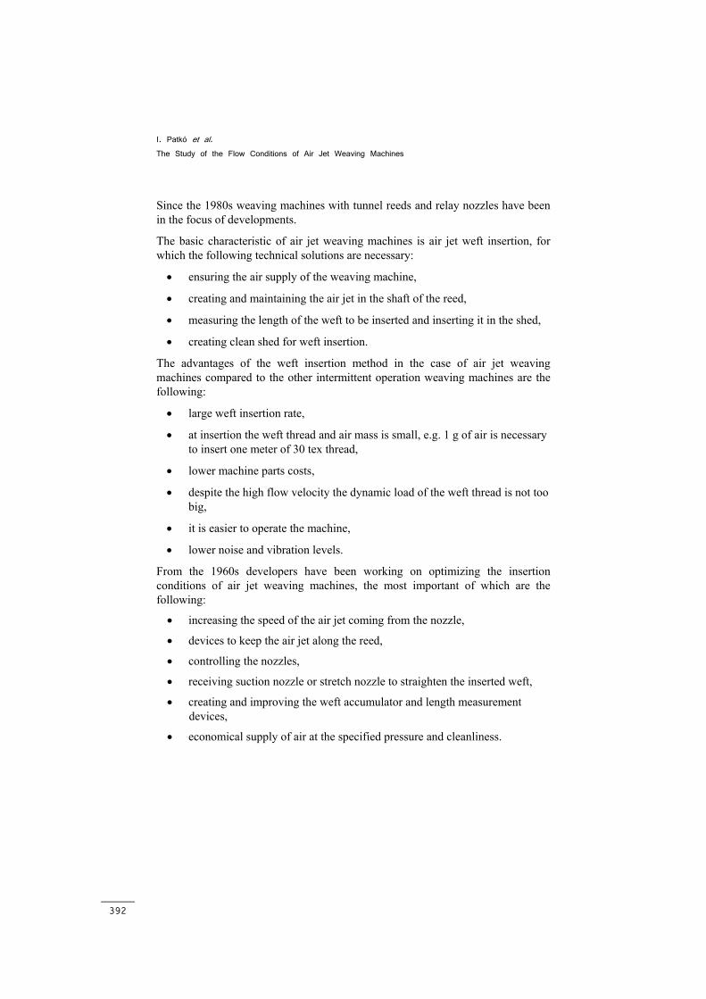
The slay is swung by crank mechanism, the air jet and weft follow the movement of the reed. From the point of view of weft insertion it is favourable if the weft is inserted in the centre line of the shed, possibly a long way from the fabric edge (Figure 1).
Figure 1
The displacement of confuser drop wire during weaving
I. Patkó et al. The Study of the Flow Conditions of Air Jet Weaving Machines
394
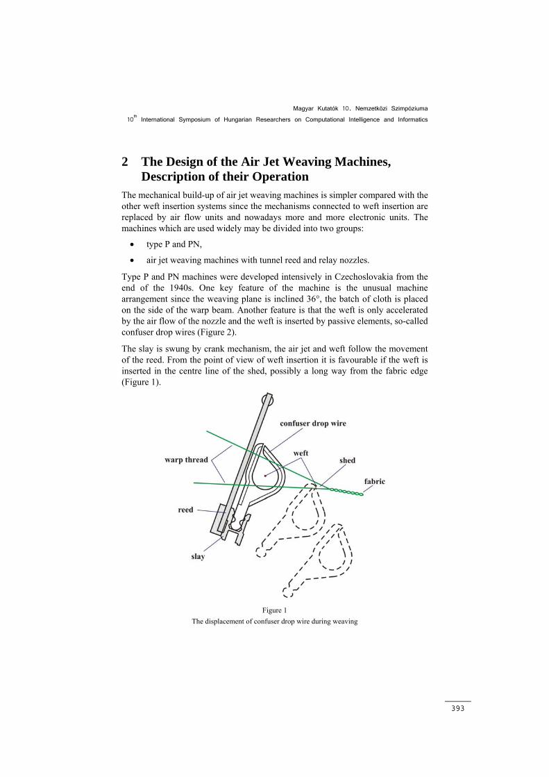
On type P weaving machines the nozzle is fixed on the machine frame and the confuser drop wires are fixed on the swaying slay. In the case of air jet guiding through confuser drop wires contracting elements, so-called confuser drop wires are placed in the axis of insertion, which decrease the dispersion of the air jet. The confuser drop wires are almost closed elements, but they are open at the top.
Figure 2 shows the arrangement of the confuser drop wires in the direction of the insertion.
Figure 2
The arrangement of the nozzle and the confuser drop wires
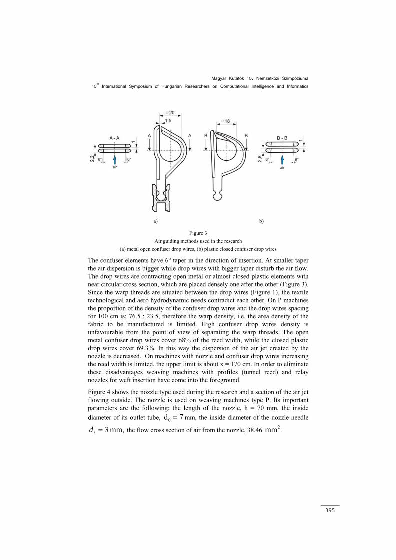
On air jet weaving machines in order to reach relatively high weft insertion rates further away from the nozzle in the line of the insertion direction, air speed may be maintained by confuser drop wires. In the research two types of confuser drop wires were examined: metal open confuser drop wires (Figure 3a) and closed plastic confuser drop wires (Figure 3b). They are 175 (245) cm in length, containing 5 (7) elements each 35 cm long. The plastic confuser drop wires have closing clappers creating an almost closed ring in terms of air flow, which make it possible for the weft stuck on the lower warp side to slip out of the confuser drop wires when the reed moves towards the fabric edge. Therefore at the upper part the air outflow from the drop wires significantly decreases – compared to the metal confuser - thus in the plastic confuser drop wires the speed drop measured in the axis of the drop wires is lower in the direction of insertion. However, the confuser drop wires are only effective if they are placed densely. The ratio of drop wire density and drop wire distance is 3 : 1, so the slot available for the warp thread is small. This highly restricts the increase in the warp density of the manufactured fabric and the confuser drop wires entering between the warp threads significantly increase the strain of the warp threads.
Magyar Kutatók 10. Nemzetközi Szimpóziuma 10th International Symposium of Hungarian Researchers on Computational Intelligence and Informatics
395
a) b)
Figure 3 Air guiding methods used in the research
(a) metal open confuser drop wires, (b) plastic closed confuser drop wires
The confuser elements have 6° taper in the direction of insertion. At smaller taper the air dispersion is bigger while drop wires with bigger taper disturb the air flow. The drop wires are contracting open metal or almost closed plastic elements with near circular cross section, which are placed densely one after the other (Figure 3). Since the warp threads are situated between the drop wires (Figure 1), the textile technological and aero hydrodynamic needs contradict each other. On P machines the proportion of the density of the confuser drop wires and the drop wires spacing for 100 cm is: 76.5 : 23.5, therefore the warp density, i.e. the area density of the fabric to be manufactured is limited. High confuser drop wires density is unfavourable from the point of view of separating the warp threads. The open metal confuser drop wires cover 68% of the reed width, while the closed plastic drop wires cover 69.3%. In this way the dispersion of the air jet created by the nozzle is decreased. On machines with nozzle and confuser drop wires increasing the reed width is limited, the upper limit is about x = 170 cm. In order to eliminate these disadvantages weaving machines with profiles (tunnel reed) and relay nozzles for weft insertion have come into the foreground.
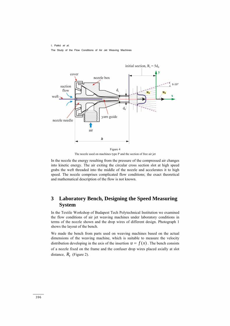
Figure 4 shows the nozzle type used during the research and a section of the air jet flowing outside. The nozzle is used on weaving machines type P. Its important parameters are the following: the length of the nozzle, h = 70 mm, the inside diameter of its outlet tube, 0d 7= mm, the inside diameter of the nozzle needle
mm, 3=td the flow cross section of air from the nozzle, 38.46 2mm .
I. Patkó et al. The Study of the Flow Conditions of Air Jet Weaving Machines
396
Figure 4
The nozzle used on machines type P and the section of free air jet
In the nozzle the energy resulting from the pressure of the compressed air changes into kinetic energy. The air exiting the circular cross section slot at high speed grabs the weft threaded into the middle of the nozzle and accelerates it to high speed. The nozzle comprises complicated flow conditions; the exact theoretical and mathematical description of the flow is not known.
3 Laboratory Bench, Designing the Speed Measuring System
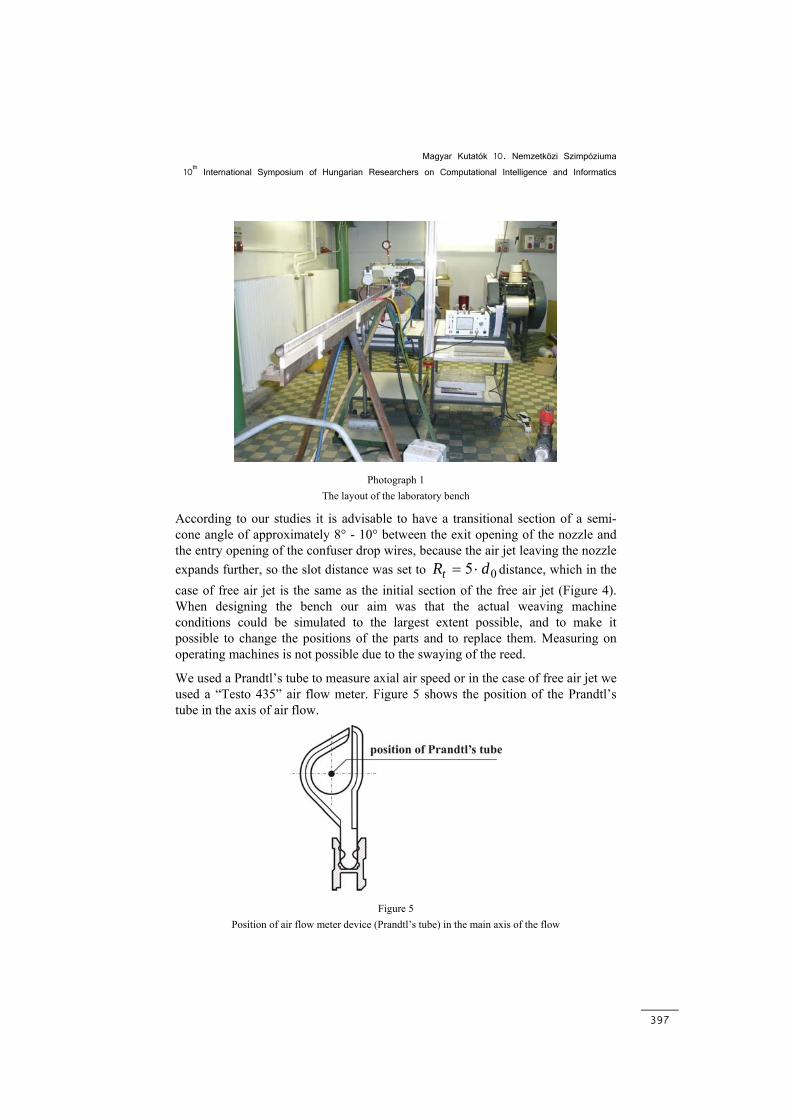
In the Textile Workshop of Budapest Tech Polytechnical Institution we examined the flow conditions of air jet weaving machines under laboratory conditions in terms of the nozzle shown and the drop wires of different design. Photograph 1 shows the layout of the bench.
We made the bench from parts used on weaving machines based on the actual dimensions of the weaving machine, which is suitable to measure the velocity distribution developing in the axis of the insertion )(xfu = . The bench consists of a nozzle fixed on the frame and the confuser drop wires placed axially at slot distance, tR (Figure 2).
Magyar Kutatók 10. Nemzetközi Szimpóziuma 10th International Symposium of Hungarian Researchers on Computational Intelligence and Informatics
397
Photograph 1
The layout of the laboratory bench
According to our studies it is advisable to have a transitional section of a semi-cone angle of approximately 8° - 10° between the exit opening of the nozzle and the entry opening of the confuser drop wires, because the air jet leaving the nozzle expands further, so the slot distance was set to 05 dRt ⋅= distance, which in the case of free air jet is the same as the initial section of the free air jet (Figure 4). When designing the bench our aim was that the actual weaving machine conditions could be simulated to the largest extent possible, and to make it possible to change the positions of the parts and to replace them. Measuring on operating machines is not possible due to the swaying of the reed.
We used a Prandtl’s tube to measure axial air speed or in the case of free air jet we used a “Testo 435” air flow meter. Figure 5 shows the position of the Prandtl’s tube in the axis of air flow.
Figure 5
Position of air flow meter device (Prandtl’s tube) in the main axis of the flow
I. Patkó et al. The Study of the Flow Conditions of Air Jet Weaving Machines
398
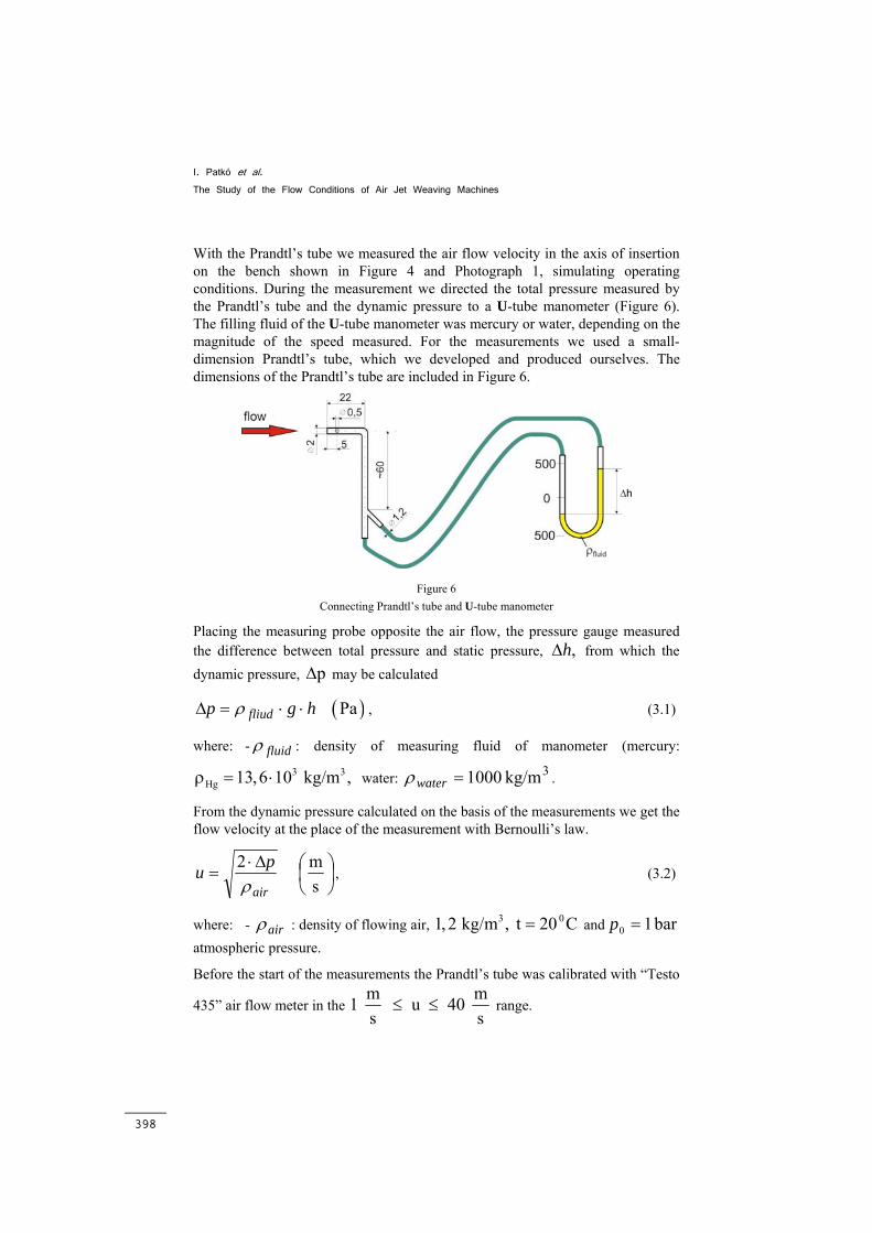
With the Prandtl’s tube we measured the air flow velocity in the axis of insertion on the bench shown in Figure 4 and Photograph 1, simulating operating conditions. During the measurement we directed the total pressure measured by the Prandtl’s tube and the dynamic pressure to a U-tube manometer (Figure 6). The filling fluid of the U-tube manometer was mercury or water, depending on the magnitude of the speed measured. For the measurements we used a small-dimension Prandtl’s tube, which we developed and produced ourselves. The dimensions of the Prandtl’s tube are included in Figure 6.
Figure 6
Connecting Prandtl’s tube and U-tube manometer
Placing the measuring probe opposite the air flow, the pressure gauge measured the difference between total pressure and static pressure, ,hΔ from which the dynamic pressure, pΔ may be calculated
hgp fliud ⋅⋅=Δ ρ ( )Pa , (3.1)
where: - fluidρ : density of measuring fluid of manometer (mercury:
3 3Hg 13,6 10 kg/m , ρ = ⋅ water: 3kg/m 1000=waterρ .
From the dynamic pressure calculated on the basis of the measurements we get the flow velocity at the place of the measurement with Bernoulli’s law.
⎟⎠⎞
⎜⎝⎛Δ⋅
=sm 2
air
puρ
, (3.2)
where: - airρ : density of flowing air, 3 01, 2 kg/m , t 20 C= and bar 10 =p atmospheric pressure.
Before the start of the measurements the Prandtl’s tube was calibrated with “Testo
435” air flow meter in the m m1 u 40 s s
≤ ≤ range.
Magyar Kutatók 10. Nemzetközi Szimpóziuma 10th International Symposium of Hungarian Researchers on Computational Intelligence and Informatics
399
4 The Theoretical Determination of the Axial Speed of Conical Free Air Jet
Free air jets with circular cross section play a very important role in technology, in different technological processes.
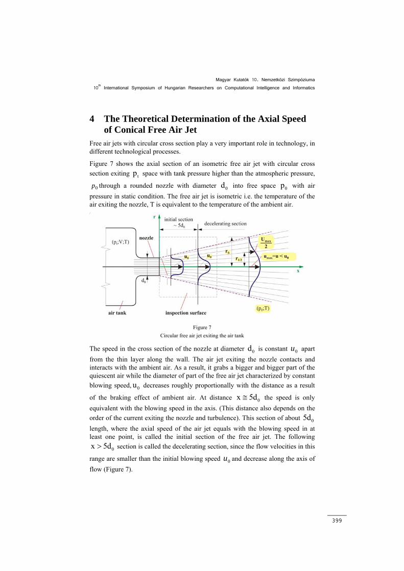
Figure 7 shows the axial section of an isometric free air jet with circular cross section exiting tp space with tank pressure higher than the atmospheric pressure,
0p through a rounded nozzle with diameter 0d into free space 0p with air pressure in static condition. The free air jet is isometric i.e. the temperature of the air exiting the nozzle, T is equivalent to the temperature of the ambient air.
Figure 7
Circular free air jet exiting the air tank
The speed in the cross section of the nozzle at diameter 0d is constant 0u apart from the thin layer along the wall. The air jet exiting the nozzle contacts and interacts with the ambient air. As a result, it grabs a bigger and bigger part of the quiescent air while the diameter of part of the free air jet characterized by constant blowing speed, 0u decreases roughly proportionally with the distance as a result
of the braking effect of ambient air. At distance 0x 5d≅ the speed is only equivalent with the blowing speed in the axis. (This distance also depends on the order of the current exiting the nozzle and turbulence). This section of about 05d length, where the axial speed of the air jet equals with the blowing speed in at least one point, is called the initial section of the free air jet. The following
0x 5d> section is called the decelerating section, since the flow velocities in this
range are smaller than the initial blowing speed 0u and decrease along the axis of flow (Figure 7).
I. Patkó et al. The Study of the Flow Conditions of Air Jet Weaving Machines
400
Instead of the ambient air mixed into the free air jet and grabbed by the air jet, outside air flows into the direction of the air jet roughly perpendicular to the axis of the free air jet. The border of the free air jet is composed of those points where the axial component of air speed is just different from zero. The distance of these points from the axis should be hr . According to experience, these points are roughly situated on a conical surface, i.e. r ~ x (Figure 7). The cone angle of these conical surfaces – depending on the order and turbulence of the medium exiting the nozzle – is around 20° - 25°.
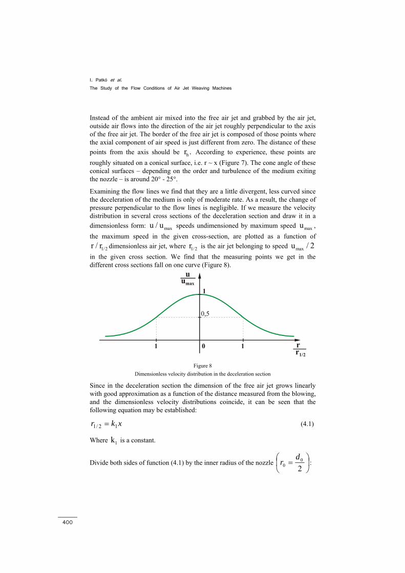
Examining the flow lines we find that they are a little divergent, less curved since the deceleration of the medium is only of moderate rate. As a result, the change of pressure perpendicular to the flow lines is negligible. If we measure the velocity distribution in several cross sections of the deceleration section and draw it in a dimensionless form: maxu / u speeds undimensioned by maximum speed maxu , the maximum speed in the given cross-section, are plotted as a function of
1/2r / r dimensionless air jet, where 1/2r is the air jet belonging to speed maxu / 2 in the given cross section. We find that the measuring points we get in the different cross sections fall on one curve (Figure 8).
Figure 8
Dimensionless velocity distribution in the deceleration section
Since in the deceleration section the dimension of the free air jet grows linearly with good approximation as a function of the distance measured from the blowing, and the dimensionless velocity distributions coincide, it can be seen that the following equation may be established:
xkr 12/1 = (4.1)
Where 1k is a constant.
Divide both sides of function (4.1) by the inner radius of the nozzle ⎟⎠⎞
⎜⎝⎛ =
20
0d
r :
Magyar Kutatók 10. Nemzetközi Szimpóziuma 10th International Symposium of Hungarian Researchers on Computational Intelligence and Informatics
401
1/2 1
0 0
r k x .r r
= (4.2)
Let’s write the momentum equation for the inspection surface seen in Figure 7 in direction x. Since the flow is stationary, there is no solid body on the inspection surface, the force resulting from friction has no projection x on the inspection surface, and the forces resulting from pressure are also negligible, we get the following from the general form of the momentum equation:
( )A
v vdA 0.ρ =∫ (4.3)
It may be concluded from (4.3) that:
2 2 20 0
A
v 2r dr v r ,ρ π = ρ π∫ (4.4)
i.e. the impulse current in any A cross-section of the free air jet equals with the impulse current in the cross-section of the blower.
Let’s make integral on the left side of equation (4.4) dimensionless so that we divide speeds u by the local maximum maxu , and the r radial coordinate by the
radius of half of the maximum speed 1/2r . After cancellations we obtain:
h 1/2r / r 22 2 2 20 0 max 1/2 2
max 1/2 1/20
u r rv r u r 2 d .u r r
= ∫ (4.5)
As a result of the previously shown identity of the dimensionless velocity distributions, the value of the integral on the right side of equation (4.5) is constant in all cross-sections of the free air jet in the deceleration section. Consequently after extraction of the root and reordering we get:
max
1/20
0
u Kons t . .rur
= (4.6)
Introducing that uu =max and considering relation (4.2) we obtain the following for the variation of maximum speed along the axis:
0
0
u Konst. .xur
= (4.7)
I. Patkó et al. The Study of the Flow Conditions of Air Jet Weaving Machines
402
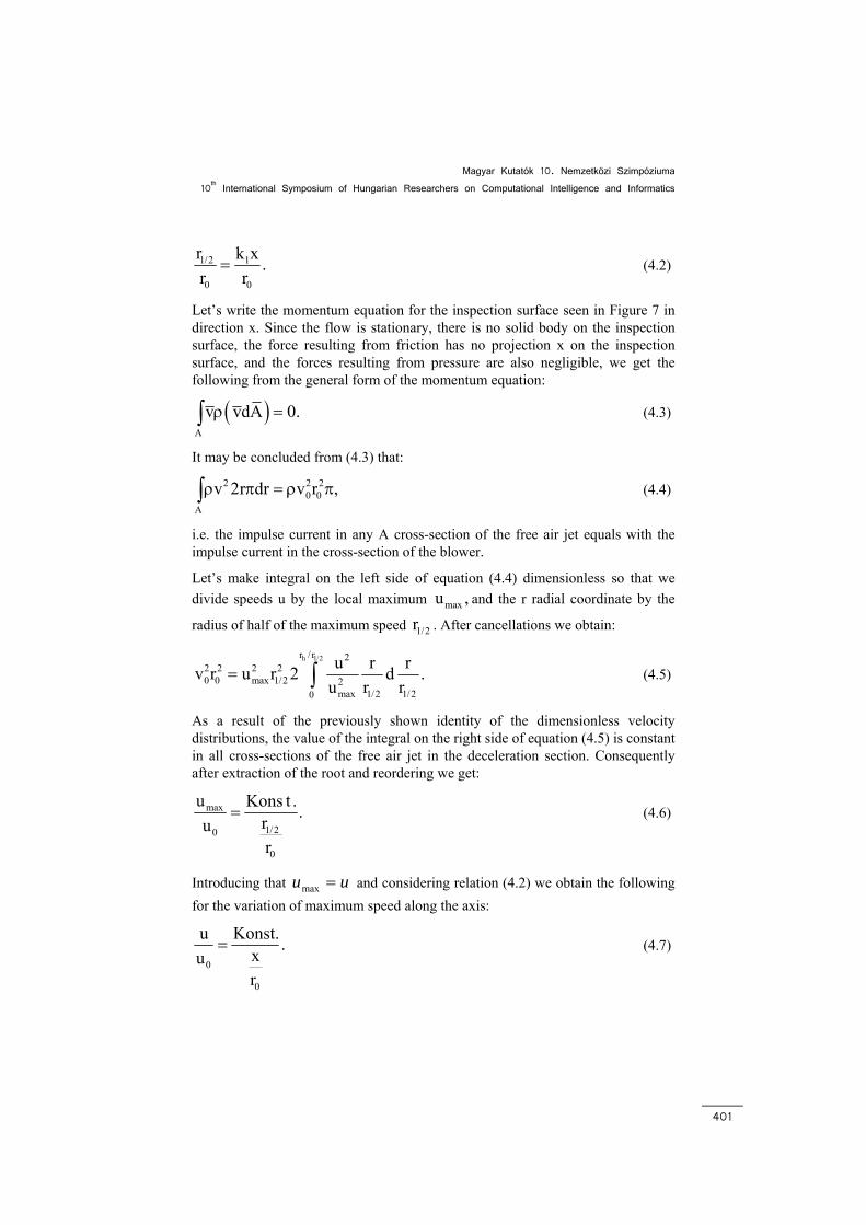
Figure 9 shows the variation in the quotient of the maximum speed in the axis of the free air jet and blower speed as a function of the measured distance, which we made dimensionless with the nozzle jet.
In the initial section of approximately 0 010r (5d ) the value of the dimensionless speed is 1, and then it decreases as a hyperbola.
Figure 9
Speed variation along the length of the free air jet
Reordering equation (4.7) we obtain the variation in maximum speed along the axis of the flow as a function of x:
'0
max 0 0r Ku u Konst. u u .x x
= = = (4.8)
These facts explain why we considered the slot distance (Figure 2) identical with the initial section of the free air jet (Figure 4).
5 Measurement of Speed and the Evaluation of Results
We made measurements to determine the speed forming in the axis of the four types of flow below:
• free air jet,
• closed tube
• open metal (Figure 3a),
• closed plastic confuser drop wires (Figure 3b).
Magyar Kutatók 10. Nemzetközi Szimpóziuma 10th International Symposium of Hungarian Researchers on Computational Intelligence and Informatics
403
During the research we measured the dynamic pressures from the beginning of the reed width at measurement points x = 0, 5, 10, 20, 30, 40, … 245 cm (Figure 2). We kept the pressure of the properly prepared compressed air at the desired, constant level, which we continuously checked with the Bourdon-tube pressure gauge built in the tank of the compressor.
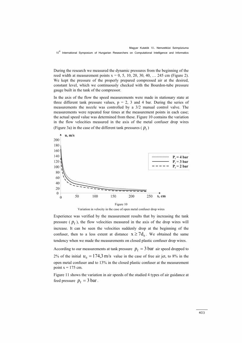
In the axis of the flow the speed measurements were made in stationary state at three different tank pressure values, p = 2, 3 and 4 bar. During the series of measurements the nozzle was controlled by a 3/2 manual control valve. The measurements were repeated four times at the measurement points in each case; the actual speed value was determined from these. Figure 10 contains the variation in the flow velocities measured in the axis of the metal confuser drop wires (Figure 3a) in the case of the different tank pressures ( tp )
Figure 10
Variation in velocity in the case of open metal confuser drop wires
Experience was verified by the measurement results that by increasing the tank pressure ( tp ), the flow velocities measured in the axis of the drop wires will increase. It can be seen the velocities suddenly drop at the beginning of the confuser, then to a less extent at distance 0x 7d≥ . We obtained the same tendency when we made the measurements on closed plastic confuser drop wires.
According to our measurements at tank pressure bar 3=tp air speed dropped to
2% of the initial m/s 3,1740 =u value in the case of free air jet, to 8% in the open metal confuser and to 13% in the closed plastic confuser at the measurement point x = 175 cm.
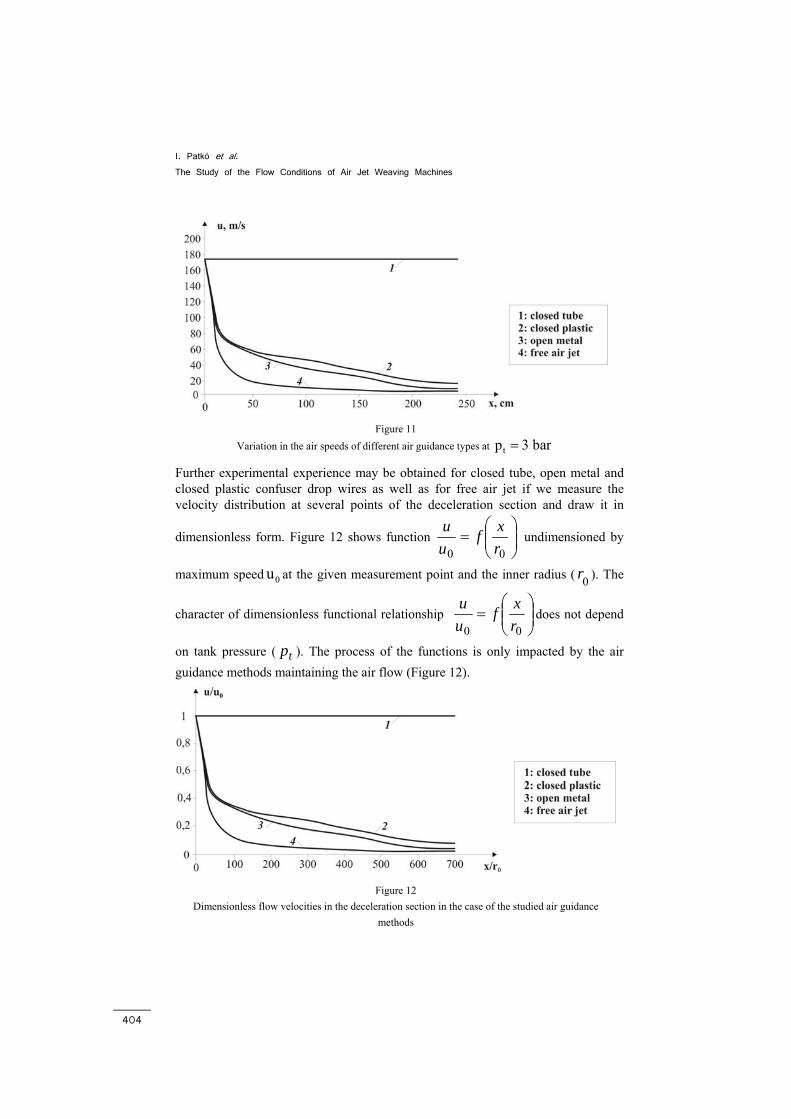
Figure 11 shows the variation in air speeds of the studied 4 types of air guidance at feed pressure bar 3=tp .
I. Patkó et al. The Study of the Flow Conditions of Air Jet Weaving Machines
404
Figure 11
Variation in the air speeds of different air guidance types at tp 3 bar=
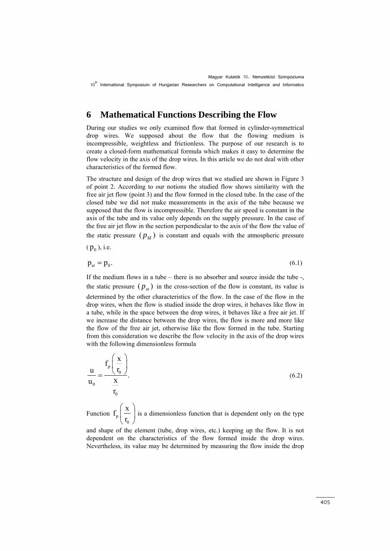
Further experimental experience may be obtained for closed tube, open metal and closed plastic confuser drop wires as well as for free air jet if we measure the velocity distribution at several points of the deceleration section and draw it in
dimensionless form. Figure 12 shows function ⎟⎟⎠
⎞⎜⎜⎝
⎛=
00 rxf
uu
undimensioned by
maximum speed 0u at the given measurement point and the inner radius ( 0r ). The
character of dimensionless functional relationship ⎟⎟⎠
⎞⎜⎜⎝
⎛=
00 rxf
uu
does not depend
on tank pressure ( tp ). The process of the functions is only impacted by the air guidance methods maintaining the air flow (Figure 12).
Figure 12
Dimensionless flow velocities in the deceleration section in the case of the studied air guidance methods
Magyar Kutatók 10. Nemzetközi Szimpóziuma 10th International Symposium of Hungarian Researchers on Computational Intelligence and Informatics
405
6 Mathematical Functions Describing the Flow During our studies we only examined flow that formed in cylinder-symmetrical drop wires. We supposed about the flow that the flowing medium is incompressible, weightless and frictionless. The purpose of our research is to create a closed-form mathematical formula which makes it easy to determine the flow velocity in the axis of the drop wires. In this article we do not deal with other characteristics of the formed flow.
The structure and design of the drop wires that we studied are shown in Figure 3 of point 2. According to our notions the studied flow shows similarity with the free air jet flow (point 3) and the flow formed in the closed tube. In the case of the closed tube we did not make measurements in the axis of the tube because we supposed that the flow is incompressible. Therefore the air speed is constant in the axis of the tube and its value only depends on the supply pressure. In the case of the free air jet flow in the section perpendicular to the axis of the flow the value of the static pressure )( stp is constant and equals with the atmospheric pressure
( 0p ), i.e.
st 0p p .= (6.1)
If the medium flows in a tube – there is no absorber and source inside the tube -, the static pressure )( stp in the cross-section of the flow is constant, its value is determined by the other characteristics of the flow. In the case of the flow in the drop wires, when the flow is studied inside the drop wires, it behaves like flow in a tube, while in the space between the drop wires, it behaves like a free air jet. If we increase the distance between the drop wires, the flow is more and more like the flow of the free air jet, otherwise like the flow formed in the tube. Starting from this consideration we describe the flow velocity in the axis of the drop wires with the following dimensionless formula
p0
0
0
xfru .xu
r
⎛ ⎞⎜ ⎟⎝ ⎠= (6.2)
Function p0
xfr
⎛ ⎞⎜ ⎟⎝ ⎠
is a dimensionless function that is dependent only on the type
and shape of the element (tube, drop wires, etc.) keeping up the flow. It is not dependent on the characteristics of the flow formed inside the drop wires. Nevertheless, its value may be determined by measuring the flow inside the drop
I. Patkó et al. The Study of the Flow Conditions of Air Jet Weaving Machines
406
wires. In our research we determined function p0
xfr
⎛ ⎞⎜ ⎟⎝ ⎠
for both drop wires that
we examined.
If we apply formula (6.2) to free air jet flow, then according to point 4
p0
xf K,r
⎛ ⎞=⎜ ⎟
⎝ ⎠ (6.3)
Where K= constant.
If we apply it to the flow inside the tube, then
p0 0
x xfr r
⎛ ⎞=⎜ ⎟
⎝ ⎠ (6.4)
from which we obtain
0
u 1u
= (6.5)
since the speed in the axis of the tube is independent of the place and its value equals with the value in the initial cross-section.
If during our studies we fix the origin of the coordinates at the cross section of the drop wires and the entry cross section of the tube according to Figures 3 and 4,
then 0
x 0,r
⎛ ⎞=⎜ ⎟⎜ ⎟
⎝ ⎠ i.e. near the initial value in the case of equations describing both
tube and drop wires flows, the undetermined form 00
⎛ ⎞⎜ ⎟⎝ ⎠
appears. This problem is
resolved by the physical fact that
0
p0
x0r
0
xfru 1xu
r
⎛ ⎞⎜ ⎟⎛ ⎞ ⎝ ⎠= ≡⎜ ⎟
⎝ ⎠ (6.6)
which means that for any flow in the initial (entry) cross-section
0
u 1,u
≡ (6.7)
Magyar Kutatók 10. Nemzetközi Szimpóziuma 10th International Symposium of Hungarian Researchers on Computational Intelligence and Informatics
407
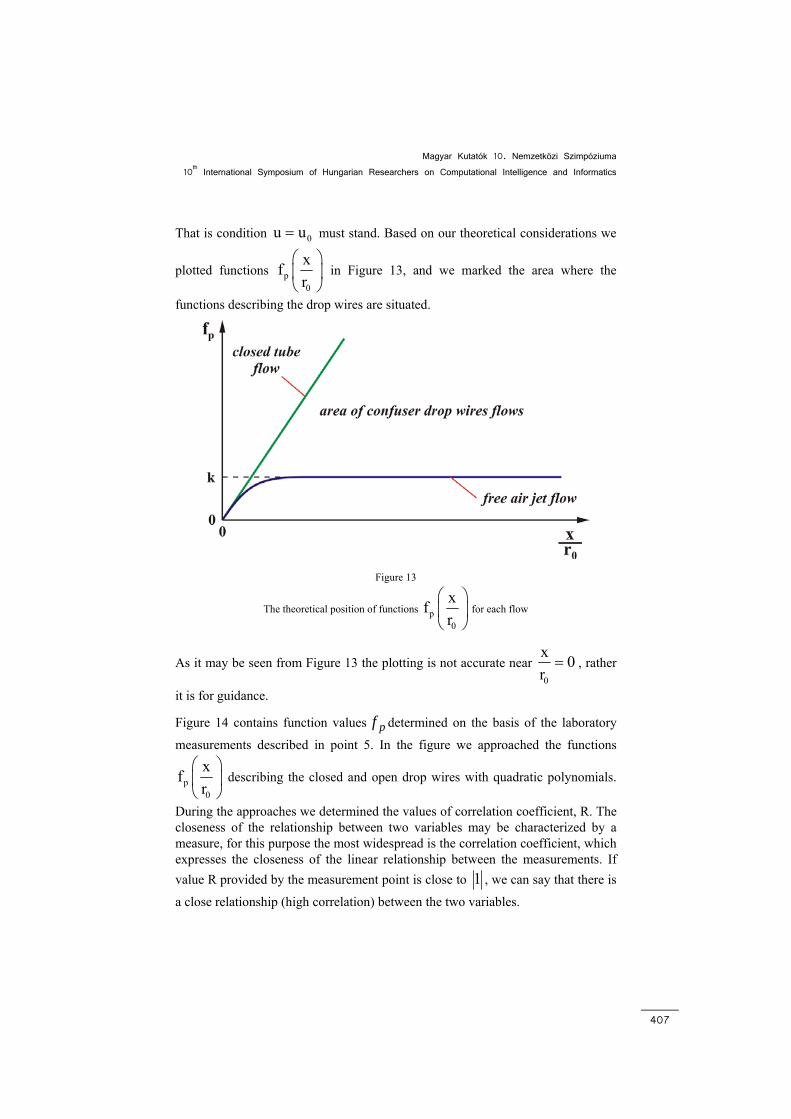
That is condition 0u u= must stand. Based on our theoretical considerations we
plotted functions p0
xfr
⎛ ⎞⎜ ⎟⎝ ⎠
in Figure 13, and we marked the area where the
functions describing the drop wires are situated.
Figure 13
The theoretical position of functions p0
xfr
⎛ ⎞⎜ ⎟⎝ ⎠
for each flow
As it may be seen from Figure 13 the plotting is not accurate near 0
x 0r= , rather
it is for guidance.
Figure 14 contains function values pf determined on the basis of the laboratory
measurements described in point 5. In the figure we approached the functions
p0
xfr
⎛ ⎞⎜ ⎟⎝ ⎠
describing the closed and open drop wires with quadratic polynomials.
During the approaches we determined the values of correlation coefficient, R. The closeness of the relationship between two variables may be characterized by a measure, for this purpose the most widespread is the correlation coefficient, which expresses the closeness of the linear relationship between the measurements. If value R provided by the measurement point is close to 1 , we can say that there is
a close relationship (high correlation) between the two variables.
I. Patkó et al. The Study of the Flow Conditions of Air Jet Weaving Machines
408
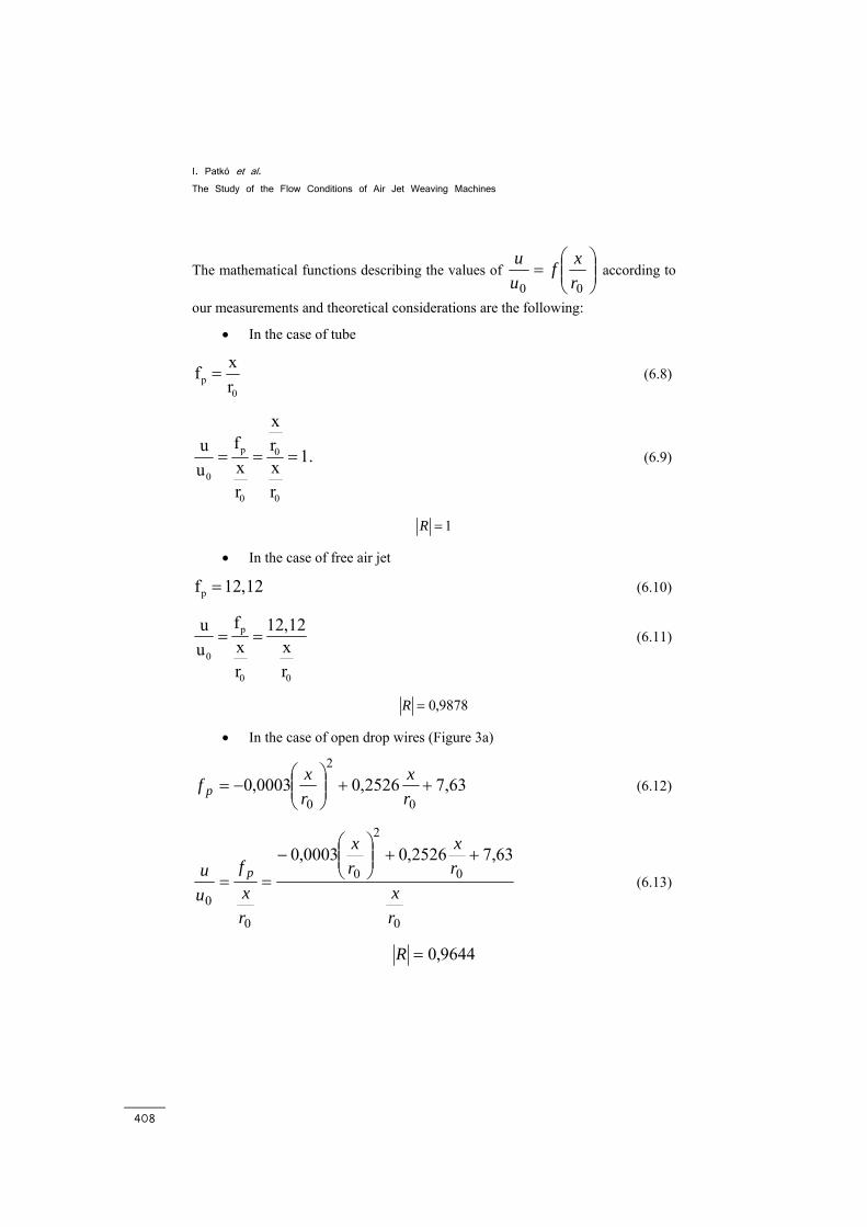
The mathematical functions describing the values of ⎟⎟⎠
⎞⎜⎜⎝
⎛=
00 rxf
uu
according to
our measurements and theoretical considerations are the following:
• In the case of tube
p0
xfr
= (6.8)
p 0
0
0 0
xf ru 1.x xur r
= = = (6.9)
1=R
• In the case of free air jet
pf 12,12= (6.10)
p
0
0 0
fu 12,12x xur r
= = (6.11)
9878,0=R
• In the case of open drop wires (Figure 3a)
63,72526,00003,00
2
0++⎟⎟
⎠
⎞⎜⎜⎝
⎛−=
rx
rxf p (6.12)
0
0
2
0
0
0
63,72526,00003,0
rx
rx
rx
rxf
uu p
++⎟⎟⎠
⎞⎜⎜⎝
⎛−
== (6.13)
9644,0=R
Magyar Kutatók 10. Nemzetközi Szimpóziuma 10th International Symposium of Hungarian Researchers on Computational Intelligence and Informatics
409
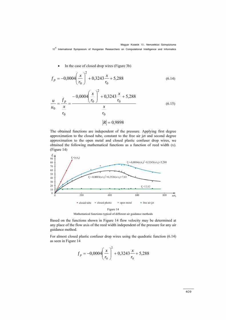
• In the case of closed drop wires (Figure 3b)
288,53243,00004,00
2
0++⎟⎟
⎠
⎞⎜⎜⎝
⎛−=
rx
rxf p (6.14)
0
0
2
0
0
0
288,53243,00004,0
rx
rx
rx
rxf
uu p
++⎟⎟⎠
⎞⎜⎜⎝
⎛−
== (6.15)
9898,0=R
The obtained functions are independent of the pressure. Applying first degree approximation to the closed tube, constant to the free air jet and second degree approximation to the open metal and closed plastic confuser drop wires, we obtained the following mathematical functions as a function of reed width (x). (Figure 14)
Figure 14
Mathematical functions typical of different air guidance methods
Based on the functions shown in Figure 14 flow velocity may be determined at any place of the flow axis of the reed width independent of the pressure for any air guidance method.
For almost closed plastic confuser drop wires using the quadratic function (6.14) as seen in Figure 14
288,53243,00004,00
2
0++⎟⎟
⎠
⎞⎜⎜⎝
⎛−=
rx
rxf p
I. Patkó et al. The Study of the Flow Conditions of Air Jet Weaving Machines
410
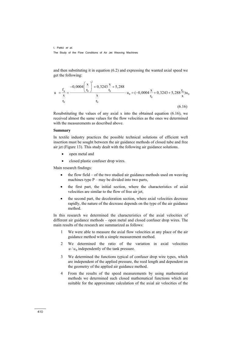
and then substituting it in equation (6.2) and expressing the wanted axial speed we get the following:
2
p 0 0 00 0
0
0 0
x x0,0004 0,3243 5,288f r r rxu u ( 0,0004 0,3243 5,288 )ux x r xr r
⎛ ⎞− + +⎜ ⎟
⎝ ⎠= = ⋅ = − + +
(6.16)
Resubstituting the values of any axial x into the obtained equation (6.16), we received almost the same values for the flow velocities as the ones we determined with the measurements as described above.
Summary
In textile industry practices the possible technical solutions of efficient weft insertion must be sought between the air guidance methods of closed tube and free air jet (Figure 13). This study dealt with the following air guidance solutions.
• open metal and
• closed plastic confuser drop wires.
Main research findings:
• the flow field – of the two studied air guidance methods used on weaving machines type P – may be divided into two parts,
• the first part, the initial section, where the characteristics of axial velocities are similar to the flow of free air jet,
• the second part, the deceleration section, where axial velocities decrease rapidly, the nature of the decrease depends on the type of the air guidance method.
In this research we determined the characteristics of the axial velocities of different air guidance methods – open metal and closed confuser drop wires. The main results of the research are summarized as follows:
1 We were able to measure the axial flow velocities at any place of the air guidance method with a simple measurement method.
2 We determined the ratio of the variation in axial velocities 0/ uu independently of the tank pressure.
3 We determined the functions typical of confuser drop wire types, which are independent of the applied pressure, the reed length and dependent on the geometry of the applied air guidance method.
4 From the results of the speed measurements by using mathematical methods we determined such closed mathematical functions which are suitable for the approximate calculation of the axial air velocities of the
Magyar Kutatók 10. Nemzetközi Szimpóziuma 10th International Symposium of Hungarian Researchers on Computational Intelligence and Informatics
411
two examined air guidance methods if we know the maximum flow velocity ( 0u ) at the entry point of the confuser drop wires (Figure 2).
The above examinations studied the air guidance systems of air jet machines with confuser drop wires during continuous flow conditions in relation to the two extreme conditions (free air jet, closed tube). However, in real conditions a dynamic effect occurs, in the stationery medium the air flow must be created in the axis of insertion several times per second (5-20).
It is possible to simulate industrial flow conditions in stationery reed position on electronically controlled weaving machines with tunnel reed.
On machines with nozzles only, the primary aspect when designing the nozzle was to create large air impulses in the insertion channel which was achieved via large quantities of air exiting a tube of large inside diameter at high speed. They managed to widen the effect of the nozzle from the beginning (free air jet) to 45, 105, 125, 155 and 165 cm, depending on the weaving needs. However, this system did not meet the needs of weft speed and further increase in width. The new principle was: in addition to the main nozzle by inserting active, relay nozzles in the axis of the insertion and making the insertion free, more advantageous (open channel) from textile technological point of view, new flow conditions occurred, air consumption changed significantly, the performance and technological possibilities increased. The main nozzle was complimented with a series pre-nozzle and modified it to have a longer accelerator tube and smaller diameter – in order to reduce air consumption. The pre-nozzle is the weft accumulator from the store, while the task of the main nozzle is restricted to accelerating the weft to a high velocity (v = 60 – 100 m/s), while distance action, large impulse is not expected. Large reed width is handled by short range relay nozzles placed densely in the axis of insertion creating short range flow. The tunnel reed weft insertion with relay nozzles shifted in the direction of free air jet flow, however, the weft insertion via confuser drop wires rather approached the flow conditions of the closed tube.
References:
[1] Patkó I.: Lamellák közötti áramlás tulajdonságainak meghatározása. Kandidátusi disszertáció, Budapest, 1994
[2] I. Patkó: The Nozzle’s Impact on the Quality of Fabric on the Pneumatic Weaving Machine
[3] G. Belforte, A. Costamagana, G. Mattiazo, F. Testore: Test Methodologies for the Measure of Main Nozzles Efficiency in Air Jet Looms, 5th World Textile Conference AUTEX 2005, 27-29 June, Portoroz, Slovenia
[4] Szabó R.: Szövőgépek. Műszaki Könyvkiadó, Budapest, 1985
[5] S. Adanur: Handbook of weaving. 2001
I. Patkó et al. The Study of the Flow Conditions of Air Jet Weaving Machines
412
[6] M. Ishida, A. Okajima, Y. Shimada, T. Kurata: Experiments of Flow of Air Jet Loom with Air Guides, Journal of the Textile Machinery Society of Japan, 1989
[7] Lajos T.: Az áramlástan alapjai. Műegyetemi Kiadó, Budapest, 2004
[8] KMF Gépészeti Tsz.: A P 165 típusú szövőgép vetülékbeviteli folyamatának fejlesztése. Kutatási jelentés. 1982
[9] W. Schneider: Flow Induced by Jets and Plumes. In. J. Fliud Mech. Vol 108 1985, pp. 55-56
[10] R. Alther: Automatische Optimierung des Schusseintrages beim Luftdüsenweben. Kanditátusi disszertáció. ETH Zürich, 1993