Embed Size (px)
Citation preview
Journal of Automation, Mobile Robotics & Intelligent Systems VOLUME 11, N° 3 2017
22
The System for EMG and MMG Signals Recording for the Bioprosthetic Hand Control
Andrzej Wołczowski, Michał Błędowski, Jerzy Witkowski
Submitted: 2nd January 2017; accepted: 2nd August 2017
DOI: 10.14313/JAMRIS_3-2017/25
Abstract:The process of biosignal acquisition has a significant im-pact on the reliability of the control of the multi-func-tional hand prosthesis. The paper discusses the nature of EMG and MMG signals and noise associated with their registration. The measuring system developed on the ba-sis of these premises, as well as the measurement proce-dure are described.
Keywords: bioprothesis, EMG, MMG, signal recognition, biosignals measurement
1. IntroductionA rehabilitation understood as a branch of medicine
aims to improve the health status and the life quality of patients. For this purpose, are commonly used techni-cal devices, an example of which are prostheses used by handless patients [1]. Increasingly popular in this area are bioprostheses controlled by signals retrieved from the patient’s body [2, 3]. The information about the pa-tient movement intentions contained in these signals, after proper recognition, control the prosthesis. Reco-gnition process, due to the time required for execution leads to the discrete control by subsequent decision commands [4, 5, 6, 7].
As carriers of information about the patient’s in-tentions most often electromyographic (EMG) and/or mechanomyographic (MMG) signals are used – rarely electro-encephalographic (EEG) signals [8, 9, 10].
Currently, designing of robotic hand is a challenge in two aspects:• to design of a multi-articulated anthropomorphic
construction, mimicking the human hand in terms of shape, weight and mobility of fingers, but also feeling of sensory interaction with the grasped object [7];
• building the control system, able to recognize the various intentions of a man (depending on the situation and type of object to be gripped) and pass them in the form of specific control commands to prostheses motor control [4, 6, 11, 12].The recognition process can be divided into four
main stages (Fig.1).
(1) On the first step bio-signals from the human body are measured. In the case of EMG and MMG si-gnals, they are recorded on the surface (on the skin) of the prosthetized limb stump (the so-called surface electromyography/mechanomyography that is com-pletely non-invasive) [5, 6, 8].
The signals are analyzed after registering to redu-ce their size by extraction (2) of appropriate features. There are many methods of signal analysis, which use different areas of the signal. For example, in the frequ-ency domain frequently used method is the Short-Ti-me Fourier Transform (STFT), and the time and fre-quency domain method of discrete wavelet transform (DWT) [14]. Features pass the selection and/or re-duction process (3) using methods such as principal component analysis (PCA) [15] or the factorization of matrix and tensor (TF) [16]. The final stage of the de-cision-making process is the classification (4), which distinguishes the class of the expected movement – that determines the decision to control [8, 9, 10].
The basic problem at hand prosthesis control is reliability in interpreting user intent. Wrong recogni-tion causes movement of the prosthesis inadequate for a situation which disorganize user action and in extreme cases can be dangerous both to user and his surroundings. Therefore, it is crucial to achieve high reliability of recognition (close to 100%).
The task of the artificial hand is to help the user in his everyday life. Depending on the type of object and the intended manipulating-gripping action, the hand should allow to diversification of its ability up to a dozen different grips. Unfortunately, along with enlarging the repertoire of possible movements of the prosthesis decreases drastically the reliability of the recognition process. Reliability depends on each step of the process component (in a simplified, ge-neral reliability is taken as the probability of correct operation. It is the product of the reliability of every subsequent steps). Therefore, it is important to opti-mize each stage. Optimization of the extraction, featu-re selection and classification were dedicated several studies [6, 10, 16, 18]. In this article we focus on the problem of optimizing the registration process of bio--signals – understood as the pursuit of registration signals (including the construction of a measurement system) that ceteris paribus, maximizes the reliabili-ty of recognition. Destiny of developed system is not only registration bio-signals for many people and for different movements but also creation a databases of signals, which allows to experimental testing of me-Fig. 1. Diagram of the recognition process

Journal of Automation, Mobile Robotics & Intelligent Systems VOLUME 11, N° 3 2017
Articles 23
thods of analysis bio-signals (including methods of extraction and feature selection and classification).
In chapter 2 was described physiology of bio-si-gnals, factors disturbing theirs registration, methods to eliminate / reduce disturbance and premises for construction of the recognition system. Chapter 3 de-scribes the recognition system and registration pro-cedure which allow both repeatability and high value of movements discrimination of recorded signals. Chapter 4 summarizes the obtained results.
2. Bio-Signals – the Nature and the Problems of Measurement
2.1. The Nature of Bio-SignalsThe activity of skeletal muscle is accompanied by
the appearance of the electric potentials, so-called myo-potentials. They are the result of movement of (Na+) and (K+) ions flowing in and out from the sur-rounding environment to the interior of muscle cells stimulated to contraction.
The contraction of the monofilament is accompli-shed on an all-or-nothing, and the strength and shrin-kage rate of the whole muscle depend on the number of activated fibers. The individual muscle fibers are activated by the incoming to them axons of motor neu-rons (called motoneurons). A single motor neuron can connect to multiple muscle cells. The cells activated simultaneously by a common motor neuron are called the motor unit of the muscle. The activity of individual motor units in the working muscle varies randomly in time. They are alternately activated (recruited) and released, but their number remains constant and is proportional to the required muscle strength.
The myocyte excitation is accompanied by a chan-ge in electrical potential between the inside of the cell and its environment from -60 mV to +50 mV. This potential change can propagate through the surroun-ding tissues, reaching up to the surface of the limb. Superposition changes potentials of all active musc-le cells can be registered on the skin over the active muscles, as the surface electromyographic signal A su-perposition of potential changes from the all active muscle cells can be registered on the skin over the ac-tive muscles as the surface electromyographic signal (EMG signal).
The rms value of the EMG signal from human ske-letal muscle, depending on their level of excitation, may be between 0–1.5 mV, and assumes the highest value in the range of 50–150 Hz.
Changes of the potentials for the individual my-ocytes have the same waveform, but their superposi-tion on the body surface, due to the spatial filtering of signals in the tissue (different damping of different frequency components), critically depends upon the spatial position of active muscle cells with respect to the locations of measurement electrodes on the skin. Hence the form of the EMG signal carries information about which muscles are active. Various movements of fingers engage different muscle groups of the fore-arm, so ultimately EMG signals carry information abo-ut the type of hand movement.
Another type of signals associated with the activi-ty of skeletal muscle are mechanical vibrations. The-
se vibrations are formed during the activation of the individual fibers in the muscle motor units, changes muscles outer geometry – during shrinkage, and fric-tion of moving relative to each other muscles as well as from the movement of tendons and joints. The vi-bration, similarly as myo-potentials, spread through the limb tissues and reach the surface, and there they superposition can be registered using a microphone or a vibrometer placed on the skin, as a mechanomyo--graphic signals (EMG signals). As in the case of EMG signals, the form of MMG signal reaching the skin sur-face also depends on the active muscles, and thus car-ries information about the type of movement.
Due to the different nature of the two types of si-gnals the contained therein information (or lack of information caused by interference) can complement each other giving the synergy effect. This will be expla-ined in section 2.2.
2.2. The Problems Accompanying the Biosignal Registration
As it has been stated in Chapter 1, the biocontrol is based on the classification of measured biosignals. To each recognized class of signal a particular decision control of the prostheses movement (or the movement other technical devices) is assigned. To the recognition of the information contained in the biosignals could be reliable the character of signals recorded during the same hand movement should always be the same (un-changed). However, both discussed above physiologi-cal phenomena which underlie the formation of bio--signals and their measurement process itself, they do not provide a constant form of signals.
The physiological cause of EMG and MMG signal changes are the changes in the recruitment pattern of motor units due to fatigue/weakness of muscle.
The fatigue is a result of changes in the concen-tration of electrochemical metabolites in the environ-ment of muscle fibers (outside the fiber membrane ac-cumulate K+ ions). Conduction velocity is reduced and the signals change The speed of propagation is redu-ced and the signals change Fatigue can be detected by monitoring the mean or median frequency or distribu-tion envelope of signal (RMS). This phenomenon must be considered in the measurement methodology.
While the external causes related to the EMG signal measurement process are: • external electromagnetic fields overlapping the
signal, and• changes in the conditions of electrode contact
with the skin (resulting from changes in skin conductance due to perspiration, changes in the composition of sweat, changes in adhesion of the electrodes, etc.).The electromagnetic smog (usually at a frequency
of 50 Hz electricity network, but also in mobile tele-phone, radio and TV bands) can induce on the skin a noise amplitude of 103 times greater than the useful signal. In turn, changes in electrode contact with the skin affected by the change ratio of the amplitude of the registered signal to noise ratio.
In the case of MMG signals, the primary source of interference is the outside noise, and (in the case of
Journal of Automation, Mobile Robotics & Intelligent Systems VOLUME 11, N° 3 2017
Articles24
a prosthesis) the sounds coming from the activity of the prosthesis and its interaction with the grasped ob-ject.
These phenomena are changing patterns of clas-ses used by the recognition algorithm, increasing the spread within the class of measured signals and thus impairing the reliability of signals recognition and control decision making. So, during the constructing of the measurement circuit you should aim to reduce these noise.
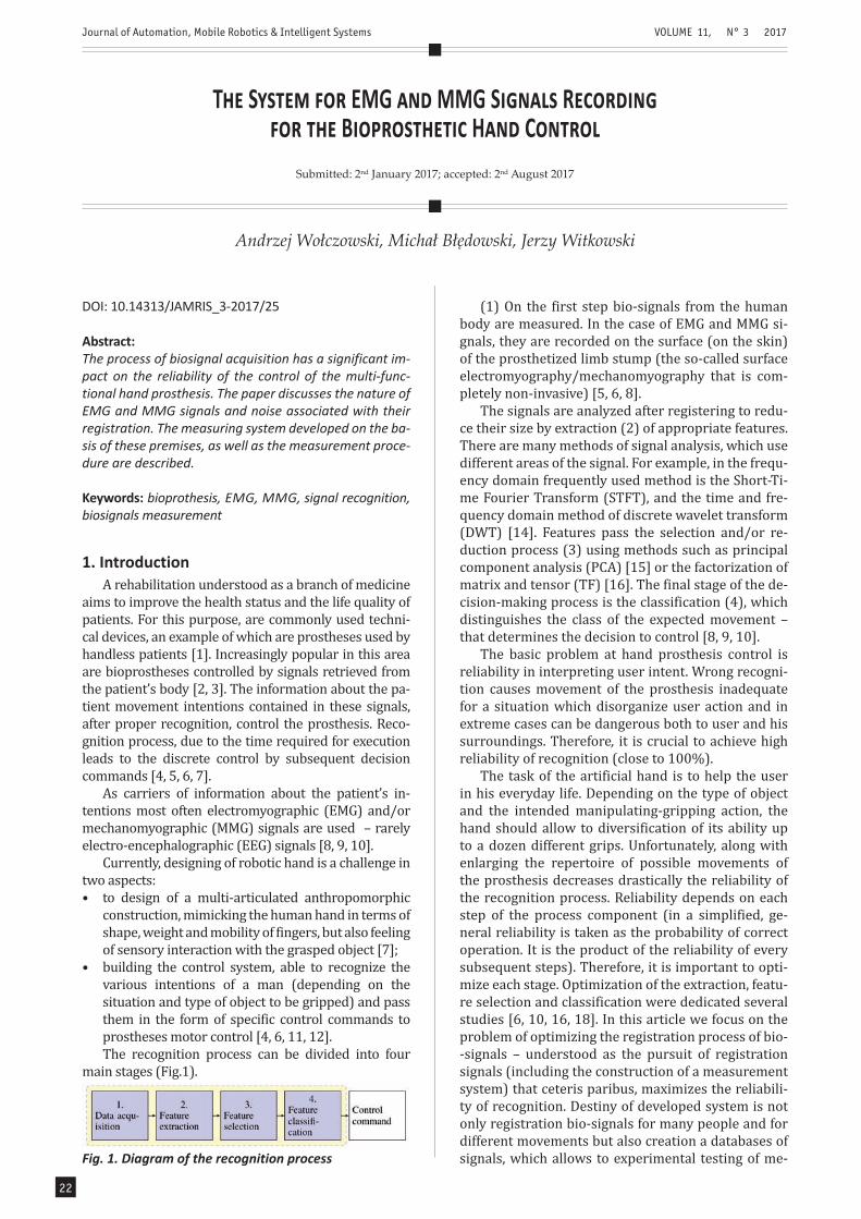
The ambient noise can be effectively eliminated by using a differential measuring system. Such a sys-tem consists of two active electrodes placed directly over the examined muscle and a reference electrode placed as far as possible, over the electrically neutral tissue (directly above the bone, joint, etc.).
The signals obtained from the active electrodes (measured relative to the reference electrode) are subtracted from each other and amplifies. The com-mon part of these signals, which is composed of back-ground noise is thus removed, and the useful signal contained in the difference of these signals is ampli-fied. The idea of differential measurement is shown in Fig. 2
terference. These disturbances are eliminated at the classification stage [18].
In commercial embodiments of prosthetic hand most often are used the measuring systems based on two electrodes [16, 17].
The presented above considerations indicates that each measuring electrode, regardless of its location on the hand stump, records signals from all active musc-les, however, as a result of spatial filtration, the greater amplitude in the registered signal have components derived from the muscles closer to the electrode.
So we can expect that for the given repertoire of prosthesis movements and for the individual ampu-tations case, there are such locations of electrodes for which the recorded signals provide the best efficacy of movements discrimination. An important part of the optimization of biosignals registration process is thus to determine on the forearm the electrode posi-tion. In the presented approach the experimental se-lection based on the number of redundant electrodes (measurement system channels) and determination of the best located electrodes by analyzing the effect of information obtained from the individual channels on the recognition quality, was proposed.
3. Bio-Signals Acquisition3.1. Measurement Setup
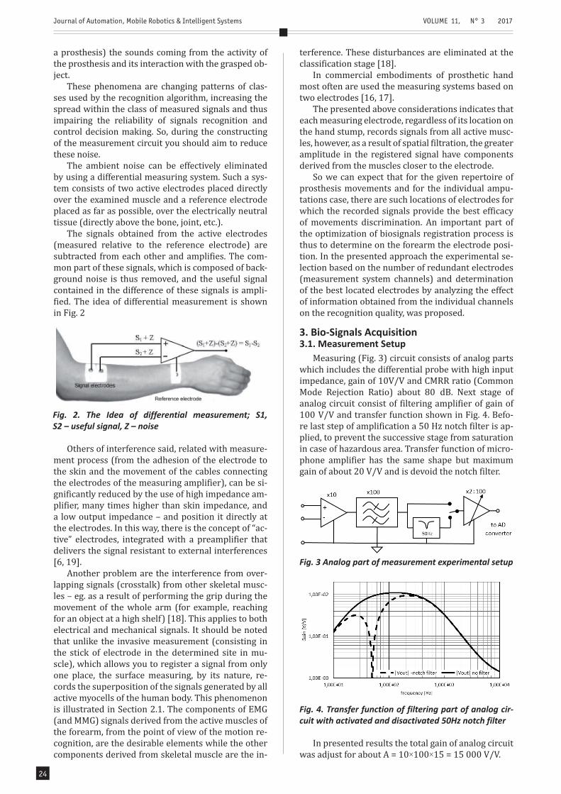
Measuring (Fig. 3) circuit consists of analog parts which includes the differential probe with high input impedance, gain of 10V/V and CMRR ratio (Common Mode Rejection Ratio) about 80 dB. Next stage of analog circuit consist of filtering amplifier of gain of 100 V/V and transfer function shown in Fig. 4. Befo-re last step of amplification a 50 Hz notch filter is ap-plied, to prevent the successive stage from saturation in case of hazardous area. Transfer function of micro-phone amplifier has the same shape but maximum gain of about 20 V/V and is devoid the notch filter.
Fig. 2. The Idea of differential measurement; S1, S2 – useful signal, Z – noise
Others of interference said, related with measure-ment process (from the adhesion of the electrode to the skin and the movement of the cables connecting the electrodes of the measuring amplifier), can be si-gnificantly reduced by the use of high impedance am-plifier, many times higher than skin impedance, and a low output impedance – and position it directly at the electrodes. In this way, there is the concept of “ac-tive” electrodes, integrated with a preamplifier that delivers the signal resistant to external interferences [6, 19].
Another problem are the interference from over-lapping signals (crosstalk) from other skeletal musc-les – eg. as a result of performing the grip during the movement of the whole arm (for example, reaching for an object at a high shelf) [18]. This applies to both electrical and mechanical signals. It should be noted that unlike the invasive measurement (consisting in the stick of electrode in the determined site in mu-scle), which allows you to register a signal from only one place, the surface measuring, by its nature, re-cords the superposition of the signals generated by all active myocells of the human body. This phenomenon is illustrated in Section 2.1. The components of EMG (and MMG) signals derived from the active muscles of the forearm, from the point of view of the motion re-cognition, are the desirable elements while the other components derived from skeletal muscle are the in-
Fig. 3 Analog part of measurement experimental setup
Fig. 4. Transfer function of filtering part of analog cir-cuit with activated and disactivated 50Hz notch filter
In presented results the total gain of analog circuit was adjust for about A = 10×100×15 = 15 000 V/V.
Journal of Automation, Mobile Robotics & Intelligent Systems VOLUME 11, N° 3 2017
Articles 25
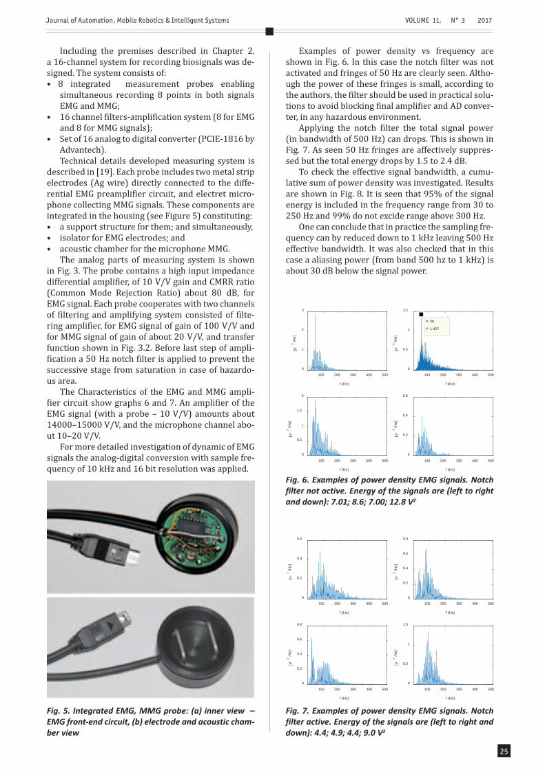
Including the premises described in Chapter 2, a 16-channel system for recording biosignals was de-signed. The system consists of:• 8 integrated measurement probes enabling
simultaneous recording 8 points in both signals EMG and MMG;
• 16 channel filters-amplification system (8 for EMG and 8 for MMG signals);
• Set of 16 analog to digital converter (PCIE-1816 by Advantech).Technical details developed measuring system is
described in [19]. Each probe includes two metal strip electrodes (Ag wire) directly connected to the diffe-rential EMG preamplifier circuit, and electret micro-phone collecting MMG signals. These components are integrated in the housing (see Figure 5) constituting:• a support structure for them; and simultaneously,• isolator for EMG electrodes; and• acoustic chamber for the microphone MMG.
The analog parts of measuring system is shown in Fig. 3. The probe contains a high input impedance differential amplifier, of 10 V/V gain and CMRR ratio (Common Mode Rejection Ratio) about 80 dB, for EMG signal. Each probe cooperates with two channels of filtering and amplifying system consisted of filte-ring amplifier, for EMG signal of gain of 100 V/V and for MMG signal of gain of about 20 V/V, and transfer function shown in Fig. 3.2. Before last step of ampli-fication a 50 Hz notch filter is applied to prevent the successive stage from saturation in case of hazardo-us area.
The Characteristics of the EMG and MMG ampli-fier circuit show graphs 6 and 7. An amplifier of the EMG signal (with a probe – 10 V/V) amounts about 14000–15000 V/V, and the microphone channel abo-ut 10–20 V/V.
For more detailed investigation of dynamic of EMG signals the analog-digital conversion with sample fre-quency of 10 kHz and 16 bit resolution was applied.
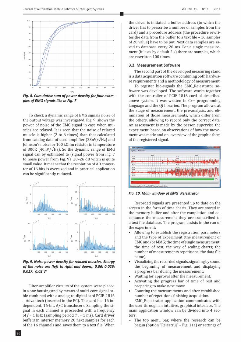
Examples of power density vs frequency are shown in Fig. 6. In this case the notch filter was not activated and fringes of 50 Hz are clearly seen. Altho-ugh the power of these fringes is small, according to the authors, the filter should be used in practical solu-tions to avoid blocking final amplifier and AD conver-ter, in any hazardous environment.
Applying the notch filter the total signal power (in bandwidth of 500 Hz) can drops. This is shown in Fig. 7. As seen 50 Hz fringes are affectively suppres-sed but the total energy drops by 1.5 to 2.4 dB.
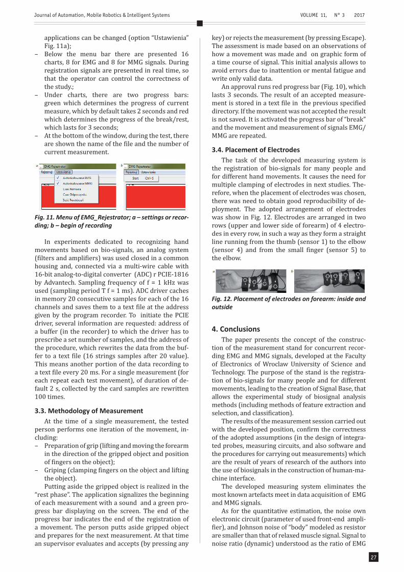
To check the effective signal bandwidth, a cumu-lative sum of power density was investigated. Results are shown in Fig. 8. It is seen that 95% of the signal energy is included in the frequency range from 30 to 250 Hz and 99% do not excide range above 300 Hz.
One can conclude that in practice the sampling fre-quency can by reduced down to 1 kHz leaving 500 Hz effective bandwidth. It was also checked that in this case a aliasing power (from band 500 hz to 1 kHz) is about 30 dB below the signal power.
Fig. 5. Integrated EMG, MMG probe: (a) inner view – EMG front-end circuit, (b) electrode and acoustic cham-ber view
100 200 300 400 500
f (Hz)
0
1
2
3
[V2
/Hz]
100 200 300 400 500
f (Hz)
0
0.5
1
1.5
[V2
/Hz]
100 200 300 400 500
f (Hz)
0
0.5
1
1.5
2
[V2
/Hz]
100 200 300 400 500
f (Hz)
0
0.2
0.4
0.6[V
2/H
z]
X: 50
Y: 1.427
Fig. 6. Examples of power density EMG signals. Notch filter not active. Energy of the signals are (left to right and down): 7.01; 8.6; 7.00; 12.8 V2
100 200 300 400 500
f (Hz)
0
0.2
0.4
0.6
[V2
/Hz]
100 200 300 400 500
f (Hz)
0
0.2
0.4
0.6
0.8
[V2
/Hz]
100 200 300 400 500
f (Hz)
0
0.2
0.4
0.6
0.8
[V2
/Hz]
100 200 300 400 500
f (Hz)
0
0.5
1
1.5
[V2
/Hz]
Fig. 7. Examples of power density EMG signals. Notch filter active. Energy of the signals are (left to right and down): 4.4; 4.9; 4.4; 9.0 V2
Journal of Automation, Mobile Robotics & Intelligent Systems VOLUME 11, N° 3 2017
Articles26
To check a dynamic range of EMG signals noise of the output voltage was investigated. Fig. 9 shows the power of noise of the EMG signal in case when mu-scles are relaxed. It is seen that the noise of relaxed muscle is higher (2 to 6 times) than that calculated from catalog data of used amplifier (28nV/√Hz) and Johnson’s noise for 100 kOhm resistor in temperature of 300K (40nV/√Hz). So the dynamic range of EMG signal can by estimated to (signal power from Fig. 7 to noise power from Fig. 9) 20–26 dB witch is quite small value. It means that the resolution of AD conver-ter of 16 bits is oversized and in practical application can be significantly reduced.
the driver is initiated, a buffer address (to which the driver has to prescribe a number of samples from the card) and a procedure address (the procedure rewri-tes the data from the buffer to a text file – 16 samples of 20 value) have to be put. Next data samples are sa-ved to database every 20 ms. For a single measure-ment (it lasts by default 2 s) there are samples, which are rewritten 100 times.
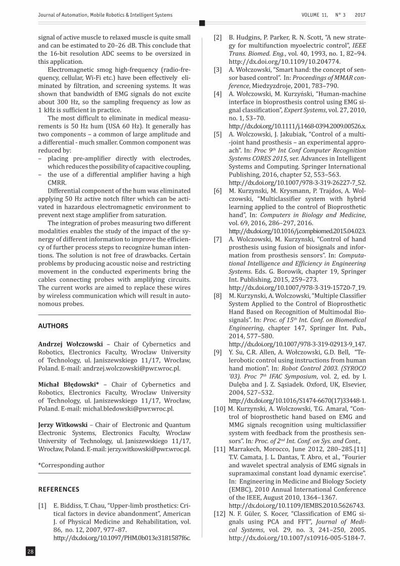
3.2. Measurement SoftwareThe second part of the developed measuring stand
is a data acquisition software combining both hardwa-re requirements and a methodology of measurement.
To register bio-signals the EMG_Rejestrator so-ftware was developed. The software works together with the controller of PCIE-1816 card of described above system. It was written in C++ programming language and the Qt libraries. The program allows, at the stage of measurement, the pre-analysis, and eli-mination of those measurements, which differ from the others, allowing to record only the correct data. An assessment is made by the person supervise the experiment, based on observations of how the move-ment was made and on overview of the graphic form of the registered signal.
0 50 100 150 200 250 300 350 400 450 500
f (Hz)
0
10
20
30
40
50
60
70
80
90
100
Ener
gy [%
]
Fig. 8. Cumulative sum of power density for four exam-ples of EMG signals like in Fig. 7
100 200 300 400 500
f (Hz)
0
2
4
6
[V2
/Hz]
10 -3
100 200 300 400 500
f (Hz)
0
0.5
1
1.5
2
[V2
/Hz]
10 -3
100 200 300 400 500
f (Hz)
0
0.5
1
1.5
[V2
/Hz]
10 -3
100 200 300 400 500
f (Hz)
0
0.5
1
1.5
[V2
/Hz]
10 -3
Fig. 9. Noise power density for relaxed muscles. Energy of the noise are (left to right and down): 0.06; 0.026; 0.017; 0.02 V2
Filter-amplifier circuits of the system were placed in a one housing and by means of multi-core signal ca-ble combined with a analog-to-digital card PCIE-1816 – Advantech (inserted in the PC). The card has 16 in-dependent, 16-bit, A/C transducers. Sampling the si-gnal in each channel is proceeded with a frequency of f = 1 kHz (sampling period T f = 1 ms). Card driver buffers in interior memory 20 next samples for each of the 16 channels and saves them to a text file. When
Fig. 10. Main window of EMG_Rejestrator
Recorded signals are presented up to date on the screen in the form of time charts. They are stored in the memory buffer and after the completion and ac-ceptance the measurement they are transcribed to a text file database. The program assists in the run of the experiment:• Allowing to establish the registration parameters
and the type of experiment (the measurement of EMG and/or MMG; the time of single measurement; the time of rest; the way of scaling charts; the number of measurements repetitions; the data file name);
• Visualizing the recorded signals, signaling by sound the beginning of measurement and displaying a progress bar during the measurement;
• Waiting for approval after the measurement;• Activating the progress bar of time of rest and
preparing to make next move• Counting the measurements and after established
number of repetitions finishing acquisition.EMG_Rejestrator application communicates with
the user through an intuitive, graphical interface. The main application window can be divided into 4 sec-tors:– The top menu bar, where the research can be
begun (option “Rejestruj” – Fig. 11a) or settings of
Journal of Automation, Mobile Robotics & Intelligent Systems VOLUME 11, N° 3 2017
Articles 27
applications can be changed (option “Ustawienia” Fig. 11a);
– Below the menu bar there are presented 16 charts, 8 for EMG and 8 for MMG signals. During registration signals are presented in real time, so that the operator can control the correctness of the study.;
– Under charts, there are two progress bars: green which determines the progress of current measure, which by default takes 2 seconds and red which determines the progress of the break/rest, which lasts for 3 seconds;
– At the bottom of the window, during the test, there are shown the name of the file and the number of current measurement.
key) or rejects the measurement (by pressing Escape). The assessment is made based on an observations of how a movement was made and on graphic form of a time course of signal. This initial analysis allows to avoid errors due to inattention or mental fatigue and write only valid data.
An approval runs red progress bar (Fig. 10), which lasts 3 seconds. The result of an accepted measure-ment is stored in a text file in the previous specified directory. If the movement was not accepted the result is not saved. It is activated the progress bar of “break” and the movement and measurement of signals EMG/MMG are repeated.
3.4. Placement of ElectrodesThe task of the developed measuring system is
the registration of bio-signals for many people and for different hand movements. It causes the need for multiple clamping of electrodes in next studies. The-refore, when the placement of electrodes was chosen, there was need to obtain good reproducibility of de-ployment. The adopted arrangement of electrodes was show in Fig. 12. Electrodes are arranged in two rows (upper and lower side of forearm) of 4 electro-des in every row, in such a way as they form a straight line running from the thumb (sensor 1) to the elbow (sensor 4) and from the small finger (sensor 5) to the elbow.
Fig. 11. Menu of EMG_Rejestrator; a – settings or recor-ding; b – begin of recording
In experiments dedicated to recognizing hand movements based on bio-signals, an analog system (filters and amplifiers) was used closed in a common housing and, connected via a multi-wire cable with 16-bit analog-to-digital converter (ADC) r PCIE-1816 by Advantech. Sampling frequency of f = 1 kHz was used (sampling period T f = 1 ms). ADC driver caches in memory 20 consecutive samples for each of the 16 channels and saves them to a text file at the address given by the program recorder. To initiate the PCIE driver, several information are requested: address of a buffer (in the recorder) to which the driver has to prescribe a set number of samples, and the address of the procedure, which rewrites the data from the buf-fer to a text file (16 strings samples after 20 value). This means another portion of the data recording to a text file every 20 ms. For a single measurement (for each repeat each test movement), of duration of de-fault 2 s, collected by the card samples are rewritten 100 times.
3.3. Methodology of MeasurementAt the time of a single measurement, the tested
person performs one iteration of the movement, in-cluding: – Preparation of grip (lifting and moving the forearm
in the direction of the gripped object and position of fingers on the object);
– Griping (clamping fingers on the object and lifting the object).Putting aside the gripped object is realized in the
“rest phase”. The application signalizes the beginning of each measurement with a sound and a green pro-gress bar displaying on the screen. The end of the progress bar indicates the end of the registration of a movement. The person putts aside gripped object and prepares for the next measurement. At that time an supervisor evaluates and accepts (by pressing any
Fig. 12. Placement of electrodes on forearm: inside and outside
4. ConclusionsThe paper presents the concept of the construc-
tion of the measurement stand for concurrent recor-ding EMG and MMG signals, developed at the Faculty of Electronics of Wroclaw University of Science and Technology. The purpose of the stand is the registra-tion of bio-signals for many people and for different movements, leading to the creation of Signal Base, that allows the experimental study of biosignal analysis methods (including methods of feature extraction and selection, and classification).
The results of the measurement session carried out with the developed position, confirm the correctness of the adopted assumptions (in the design of integra-ted probes, measuring circuits, and also software and the procedures for carrying out measurements) which are the result of years of research of the authors into the use of biosignals in the construction of human-ma-chine interface.
The developed measuring system eliminates the most known artefacts meet in data acquisition of EMG and MMG signals.
As for the quantitative estimation, the noise own electronic circuit (parameter of used front-end ampli-fier), and Johnson noise of “body” modeled as resistor are smaller than that of relaxed muscle signal. Signal to noise ratio (dynamic) understood as the ratio of EMG
Journal of Automation, Mobile Robotics & Intelligent Systems VOLUME 11, N° 3 2017
Articles28
signal of active muscle to relaxed muscle is quite small and can be estimated to 20–26 dB. This conclude that the 16-bit resolution ADC seems to be oversized in this application.
Electromagnetic smog high-frequency (radio-fre-quency, cellular, Wi-Fi etc.) have been effectively eli-minated by filtration, and screening systems. It was shown that bandwidth of EMG signals do not excite about 300 Hz, so the sampling frequency as low as 1 kHz is sufficient in practice.
The most difficult to eliminate in medical measu-rements is 50 Hz hum (USA 60 Hz). It generally has two components – a common of large amplitude and a differential - much smaller. Common component was reduced by:– placing pre-amplifier directly with electrodes,
which reduces the possibility of capacitive coupling,– the use of a differential amplifier having a high
CMRR.Differential component of the hum was eliminated
applying 50 Hz active notch filter which can be acti-vated in hazardous electromagnetic environment to prevent next stage amplifier from saturation.
The integration of probes measuring two different modalities enables the study of the impact of the sy-nergy of different information to improve the efficien-cy of further process steps to recognize human inten-tions. The solution is not free of drawbacks. Certain problems by producing acoustic noise and restricting movement in the conducted experiments bring the cables connecting probes with amplifying circuits. The current works are aimed to replace these wires by wireless communication which will result in auto-nomous probes.
AUTHORS
Andrzej Wołczowski – Chair of Cybernetics and Robotics, Electronics Faculty, Wroclaw University of Technology, ul. Janiszewskiego 11/17, Wrocław, Poland. E-mail: [email protected].
Michał Błędowski* – Chair of Cybernetics and Robotics, Electronics Faculty, Wroclaw University of Technology, ul. Janiszewskiego 11/17, Wrocław, Poland. E-mail: [email protected].
Jerzy Witkowski – Chair of Electronic and Quantum Electronic Systems, Electronics Faculty, Wroclaw University of Technology, ul. Janiszewskiego 11/17, Wrocław, Poland. E-mail: [email protected].
*Corresponding author
REFERENCES
[1] E. Biddiss, T. Chau, “Upper-limb prosthetics: Cri-tical factors in device abandonment”, American J. of Physical Medicine and Rehabilitation, vol. 86, no. 12, 2007, 977–87.
http://dx.doi.org/10.1097/PHM.0b013e3181587f6c.
[2] B. Hudgins, P. Parker, R. N. Scott, “A new strate-gy for multifunction myoelectric control”, IEEE Trans. Biomed. Eng., vol. 40, 1993, no. 1, 82–94. http://dx.doi.org/10.1109/10.204774.
[3] A. Wołczowski, “Smart hand: the concept of sen-sor based control”. In: Proceedings of MMAR con-ference, Miedzyzdroje, 2001, 783–790.
[4] A. Wołczowski, M. Kurzyński, “Human-machine interface in bioprosthesis control using EMG si-gnal classification”, Expert Systems, vol. 27, 2010, no. 1, 53–70.
http://dx.doi.org/10.1111/j.1468-0394.2009.00526.x.[5] A. Wolczowski, J. Jakubiak, “Control of a multi-
-joint hand prosthesis – an experimental appro-ach”. In: Proc 9th Int Conf Computer Recognition Systems CORES 2015, ser. Advances in Intelligent Systems and Computing. Springer International Publishing, 2016, chapter 52, 553–563.
http://dx.doi.org/10.1007/978-3-319-26227-7_52.[6] M. Kurzynski, M. Krysmann, P. Trajdos, A. Wol-
czowski, “Multiclassifier system with hybrid learning applied to the control of Bioprosthetic hand”, In: Computers in Biology and Medicine, vol. 69, 2016, 286–297, 2016.
http://dx.doi.org/10.1016/j.compbiomed.2015.04.023.[7] A. Wolczowski, M. Kurzynski, “Control of hand
prosthesis using fusion of biosignals and infor-mation from prosthesis sensors”. In: Computa-tional Intelligence and Efficiency in Engineering Systems. Eds. G. Borowik, chapter 19, Springer Int. Publishing, 2015, 259–273.
http://dx.doi.org/10.1007/978-3-319-15720-7_19.[8] M. Kurzynski, A. Wolczowski, “Multiple Classifier
System Applied to the Control of Bioprosthetic Hand Based on Recognition of Multimodal Bio-signals”. In: Proc. of 15th Int. Conf. on Biomedical Engineering, chapter 147, Springer Int. Pub., 2014, 577–580.
http://dx.doi.org/10.1007/978-3-319-02913-9_147.[9] Y. Su, C.R. Allen, A. Wołczowski, G.D. Bell, “Te-
lerobotic control using instructions from human hand motion”. In: Robot Control 2003. (SYROCO ’03). Proc 7th IFAC Symposium, vol. 2, ed. by I. Dulęba and J. Z. Sąsiadek. Oxford, UK, Elsevier, 2004, 527–532.
http://dx.doi.org/10.1016/S1474-6670(17)33448-1.[10] M. Kurzynski, A. Wolczowski, T.G. Amaral, “Con-
trol of bioprosthetic hand based on EMG and MMG signals recognition using multiclassifier system with feedback from the prosthesis sen-sors”. In: Proc. of 2nd Int. Conf. on Sys. and Cont.,
[11] Marrakech, Morocco, June 2012, 280–285.[11] T.V. Camata, J. L. Dantas, T. Abro, et al., “Fourier and wavelet spectral analysis of EMG signals in supramaximal constant load dynamic exercise”. In: Engineering in Medicine and Biology Society (EMBC), 2010 Annual International Conference of the IEEE, August 2010, 1364–1367.
http://dx.doi.org/10.1109/IEMBS.2010.5626743.[12] N. F. Güler, S. Kocer, “Classification of EMG si-
gnals using PCA and FFT”, Journal of Medi-cal Systems, vol. 29, no. 3, 241–250, 2005. http://dx.doi.org/10.1007/s10916-005-5184-7.
Journal of Automation, Mobile Robotics & Intelligent Systems VOLUME 11, N° 3 2017
Articles 29
[13] A. Cichocki, R. Zdunek, A. Phan, S. Amari, Nonne-gative Matrix and Tensor Factorizations: Applica-tions to Exploratory Multi-way Data Analysis and Blind Source Separation, Wiley and Sons, 2009. http://dx.doi.org/10.1002/9780470747278.
[14] H. M. Al-Angari, G. Kanitz, S. Tarantino, C. Ci-priani, “Distance and mutual information me-thods for EMG feature and channel subset se-lection for classification of hand movements”, Biomedical Signal Processing and Control, vol. 27, May 2016, 24–31.
http://dx.doi.org/10.1016/j.bspc.2016.01.011.[15] A. Wołczowski, J. S. Witkowski, Stanowisko ba-
dawcze do akwizycji biosygnałów, Report of the Institute of Computer Engineering, Control and Robotics of Wroclaw University of Technology 2013, Ser. PRE no. 47, Wrocław, 2013. (in Polish)
[16] W. Sobczak, W. Malina, Metody selekcji i redukcji informacji, WNT, Warsaw, 1985. (in Polish)
[17] C.J. De Luca, Electromyography. Encyclopedia of Medical Devices and Instrumentation, John Wiley Publisher, 2006, 98–109.
[18] bebionic, http://bebionic.com/the_hand/grip_ patterns/key_grip
[19] ottobock, http://www.ottobock.pl/[20] delsys http://www.delsys.com/