Embed Size (px)
Citation preview

Z
R. & M. No. 3481
A g ~ C ~ L ~ ! : 5 ~ -.,~-~.,,~, . . . . ~ . ~ * ~ - -,~,
M I N I S T R Y O F T E C H N O L O G Y
AERONAUTICAL RESEARCH COUNCIL
REPORTS AND MEMORANDA
The Transonic Flow in the Throat Region of a
Two-Dimensional Nozzle with Walls of
Arbitrary Smooth Profile
b y A . W . MOORE, P h . D .
L O N D O N : HER MAJESTY'S STATIONERY O F F I C E
1967
PRICE lls. 0d. NET

The Transonic Flow in the Throat Region of a
Two-Dimensional Nozzle with Walls of
Arbitrary Smooth Profile by A. W. MOORE, P h . D .
COMMUNICATED BY PROF. N. H. JOHANNESEN
Reports and Memoranda No. 3481 *
January, 1965
Summary.
A solution is presented for the flow in the throat region of a two-dimensional nozzle with an arbitrary smooth profile. The velocity components are determined as series expansions in ascending powers of R -~ where R is the mean radius of curvature of the profile at the throat measured in throat half-heights. The first three terms of the series solution are given, and some properties of the flow are determined for two special cases, namely the configurations in which the nozzle is asymmetric about the longitudinal axis and in which the nozzle profile is described by a cubic equation.
The solution of the indirect problem is also discussed. An axial velocity distribution of arbitrary form is assumed and the velocity components are obtained as series expansions in terms of the non-dimensional velocity gradient b 1 along the axis at the throat. The coefficients of each power of this parameter are determined as closed expressions. The parameters which describe the shape of the nozzle walls (stream- lines) are calculated.
Section
1.
2.
3.
4.
LIST OF CONTENTS
Introduction
The Direct Solution
The Flow Field
Special Cases
4.1 Asymmetry about the x-axis
4.2 Asymmetry about the y-axis
4.3 Flow in a choking wind tunnel
5. The Inverse Problem
Acknowledgement
List of Principal Symbols
References
Illustrations--Figs. 1 to 11
*Replaces A.R.C. 26 542.

1. I n t r o d u c t i o n .
The transonic flow in the throat region of Laval nozzles has been of interest since the start of the 19th century. One-dimensional analyses of the flow were developed and are summarized in a review by Prandtl ~°. A two-dimensional analysis of the flow can be obtained by either of two methods. In the indirect method, the axial velocity distribution is prescribed, and the corresponding family of nozzles (streamlines) is calculated. The direct problem in which the flow through a nozzle of given shape is deter- mined is more difficult.
Using the indirect approach, the solution is straightforward in principle and was first investigated by Meyer 9. He assumed a linearly increasing velocity along the axis of symmetry and, by direct substitution of a double power series for the velocity potential into the basic equations, he obtained a series solution up to and including the sixth-order terms. He went on to show that the streamlines were convergent- divergent as in a Laval nozzle. It was apparent, however, that the solution was only satisfactory in a region close to the origin. Unfortunately, with this type of approach, the size of this region could not be determined. Since then, many papers considering either the indirect or direct problem have been written on this subject. These are discussed in a survey presented by Hall and Sutton s.
Until recently, only. first approximations to the solution of the direct problem were available. A method of generating higher approximations was developed by Hall 4, but was only applied to doubly-symmetric parab0_lic-arc nozzles. In the present investigation, Hall's method of successive approximation is general- ized, and it is shown how it can be extended to apply to asymmetric nozzles. The only limitation to the approach is that neither of the nozzle walls may have a small radius of curvature. Within this limitation, the transonic flow through the throat of any nozzle of arbitrary smooth profile is determined in analytic form.
The method of solution is to seek to determine the velocity components in the throat region as series expansions in terms of inverse powers of R ~, where R can be regarded as the radius of curvature of the equivalent symmetric nozzle referred to the throat half-height as the unit of length. The equivalent symmetric,nozzle is the one having the same second derivative of area increase at the throat as the asymmetric nozzle. R is thus defined by
1 r 1 (1"1) = kS\T J :o
where A is the cross-sectional area near the throat. Fig. 1 shows the throat region of a typical asymmetric nozzle with finite throat curvature; the equivalent symmetric nozzle is indicated by the broken lines.
The generality of the approach leads to lengthy expressions for the coefficients of the higher powers of R -~. For this reason, the series are only given as far as the third approximation (corresponding to Hall's 'second' approximation because alternate terms are zero in the symmetric case). In some cases, this may not describe the flow to a sufficient degree of accuracy. However, the algebraic complexity is such that if it is desired to extend the solution for practical use, it is recommended that numerical values are assigned at an early stage and the analysis carried out with numerical coefficients.
Two special cases which allow considerable simplification of the expressions are considered in more detail. The first restricts the nozzle walls to be parabolic but with different radii of curvature (circular, hyperbolic and parabolic arcs are equivalent unless terms of O ( R - 3) are included) and the other considers the flow through a symmetric nozzle with walls having a cubic profile. The positions of the sonic line and the branch line are determined. It is noted that for some asymmetric nozzles, a branch line is present although there is not a singular point in the real flow. This is because there is always a singular point in the mathematical continuation of the flow outside the nozzle walls. The rate of mass flow is calculated for each case. A further special case in which one wall is straight is used to demonstrate the application of the theoretical analysis to the flow in a choked wind tunnel.
A general solution of the inverse problem is determined. Arbitrary velocity distributions of the form
u 1 - t - b l ( x - t d b 2 x 2 - t - b 3 x 3 - 4 - . .) (1.2) a #
2
V a--d = c l x + c 2 x 2 + . . . (1.3)
where the ' b n s ' and ' cns ' are constants, are assumed along the x-axis. Since b 1 is O ( R - ~ ) to a first approxi- mation, a method of solution consistent with the direct approach is adopted in which the velocity
componen t s are sought as series expansions in increasing powers of bl. Using these expansions, the nozzle characteristics can also be expressed as series in increasing powers of bl, the coefficient of each power being obtained as a closed expression in each case. Hence, when the series is terminated at any power of bl, the order of magnitude of the neglected terms is known. The double power series expansion used by previous authors does not have this advantage.
An obvious application of the direct solution is the calculation of the flow through sliding block nozzles. It also givrs the solution for a small region of the choking flow past smooth bodies placed in a solid wall wind tunnel. Since no suitable experimental results are available in the two-dimensional case, this configuration is not discussed here. A discussion of this flow in the axially-symmetric case is given by Moore and Hall s .
Although the nozzle is assumed to have an arbitrary smooth profile, the solution obtained is not completely general, because it cannot be used in two extreme cases, namely when R is very small or when R is infinite.
The solution will break down for small values of R because of the slow convergence of the series expansions. The physical reasons for this are dear. When R is small, there is a large lateral variation of velocity across the flow, and conditions in the region of the narrowest cross-section of the nozzle cannot be said to be transonic. For instance, the velocity will be significantly greater than sonic at stations close to the h~ghly curved wall and significantly less at the centre of the throat. The assumption that the axial component of velocity is almost equal to the critical speed of sound is therefore no longer true. Any satisfactory solution would necessarily include the solution of the 'elliptic' subsonic region.
When R is infinite, the nozzle walls have zero curvature at the throat. This configuration would be produced if the nozzle profile had the form
Y = l + a l x l n + . . . , n > 2 . (1.4)
When n = 3, for example, equation (1.4) represents a double-cubic nozzle. This type of nozzle could be obtained by matching two cubic profiles at the throat such that if the nozzle was completely symmetric, the downstream profile would be a mirror image of the upstream profile. The nozzle Would have continu- ous curvature at the throat but discontinuous third derivative. The sonic line is apparently straight for this case.
Frankl 1 and Grr t ler a have given some attention to the flow through a nozzle with R = o~. They used the indirect method of solution to examine the conditions which would result in a straight sonic line, and obtained the leading terms of a series for the velocity potential when the axial velocity distributions are given by
u = 1 + K x 2
a n d
u = 1 + K x a
respectively, where K is a constant. They showed that in these cases, the sonic line lay along the y-axis. Configurations with R = oe are unlikely to have practical use because the boundary-layer growth would be the dominant factor in determining the flow.
Using the present method, the shape of the nozzle profile in the throat region provides sufficient boundary conditions for a solution to be obtained. This arouses some doubts regarding the uniqueness of the solution because in the region upstream of the throat, the flow is governed by an elliptic differential equation which requires boundary conditions to be given on the entire periphery. However, the present

conditions are peculiar to some extent since the equations must change from elliptic to hyperbolic form across the sonic line. Near to this line, the equations are, in some sense, 'approximately' parabolic, in which case 'end' conditions only can be sufficient to obtain a solution.
In physical terms, this means that the shape of the nozzle walls in the throat region will have little effect upstream, but will dominate the flow between them. This is similar to the flow in a wind tunnel in which the upstream region of influence of a model decreases to zero as the velocity of the flow is in- creased from subsonic to supersonic speeds. At high subsonic speeds, the model imparts little disturbance to upstream or downstream flow, but in the transverse direction, its influence is large.
The solution for the flow in the throat region given by the present method has been used by McCabe 7 in the design of a supersonic nozzle. Consistent results were obtained using different starting character- istics. This gives some indication that the solution is satisfactory.
It has been shown by Freeman z that the present method of solution is not uniformly valid at infinity. It is also true that the solution will not be valid if there is a stagnation point near the throat region. This situation could occur if the upstream nozzle profile was discontinuous. For the same reason, the solution can only be applied to a small region of the flow past a body in a choking wind tunnel since there is a stagnation point at the leading edge of the body. The effect of a discontinuity in the nozzle profile well upstream of the throat is not clear. If it is sufficiently far upstream, it apparently has no effect.
2. The Direct Solution
For ~ nozzle with any arbitrary smooth profile, the shapes of the walls can be written in the form
h= h(O)+x(dh'~ l zl'dZh'~ 1 3['d3h'~ +~x t~X2)o+~X t)-~-gX3)o+ .. (2.1)
/ dj'~ , 1 2{ d2j ~ 1 3 ( d3j'~ J = J(°)+x t )o+g x t jo + " (2.2)
where h, j are shown in Fig. 1. Some simplification of the early terms can be made by choosing the origin of co-ordinates to be in
the plane of the throat, and by choosing the unit of length so that
h(0) = j(0) = 1.
Since the cross-sectional area at the origin is a minimum,
- -0 d x ] o o
(2.3)
Hence, if the axes are orientated so that
d ( ~x ) o = ( dx dj) o (2.4)
comparison with equation (2.3) shows that
(dD o = o = 0 . ( 2 . 5 )
Thus, without any loss in generality, the constants in equations (2.1) and (2.2) have been made unity, and the terms in x have been eliminated.

For the nozzle with a simple symmetric profile, the solutions for the velocity components have been obtained as expansions in inverse powers of the radius of curvature of the nozzle walls 4. In the present case, the walls will not, in general, have the same radius of curvature, and it is convenient to define a mean value, R, by

The velocity components u and v in the axial and transverse directions respectively must satisfy the condition of irrotationality and the equation of continuity which, in terms of perturbation velocities u'
t and v, are
~3v' Off Ox- Oy (2.16)
and
__2U,__U,Z__Y 1 2) C~U' 4 ~_~' 7 + l V ' Ox 7 + l ( l + u ' ) v '
( 2 v, 2 2(7-1)u,_Y-luzz) 0v' + \ 7 + 1 7 + ~ 7+1 -~y = 0 (2.17)
where
u 1 + u' (2.18) a *
v = ~ = v' (2.19)
and a* is the critical speed of sound. Order of magnitude arguments indicate that u' is O(e 2) and v' is O(e 3) in the throat region where x is restricted to be O(e). A convenient substitution, which introduces a stretched co-ordinate z, is
x = (? + 1)~z (2.20)
which means that the independent variables z and y are both of order unity. The solution of equations (2.16) and (2.17) is now sought in terms of y and z instead of y and x.
The equations for the profiles of the nozzle walls indicate that the series expansion for the velocity components used by Hall 4 will not be adequate for the more general case considered here. The expansions must be in ascending powers of e, i.e.,
U' = ~;2Ui(y , Z)+ gaU2(y, Z)+ g4U3(y, Z)+ . . . . (2.21)
Equations (2.16) and (2.20) then show that the corresponding expansion for v' is
v' = (y+ 1)~[eavl(y, z)+d~v2(Y, z)+ eSva(y, z)+ . . . ] . (2.22)
Substituting for u' and v' in equations (2.16) and (2.17), and considering the coefficients of each power of e separately yields two sets of equations, which are
and
~Vn cqu,, (n/> 1) (2.23) az coy
- u i - ~ z + ~ = 0 (2.24)
au. Oul &. -Ul a--z - u " z o y a - + ~ - = ~ , - 1 (2.25)
where O,_ , is a function of u l , . . . . u,_ 1, v l , . . . ; v,_ 1, only. The functions O1 and 0 2 a r e
O1 = 0 (2.26)
02 = 2vl ~ z * + ( y - 1) Or1 - - 1 2 0/~1 0112 (2.27)
Two sets of boundary conditions are obtained by substituting for u' and v' in the equations
v' dh - - - a t y = h 1 +u' dx
(2.28)
v' aj - - - at y = - j (2.29) 1 + u' dx
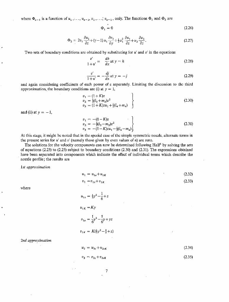
and again considering coefficients of each power of e separately. Limiting the discussion to the third approximation, t he boundary conditions are (i) at y = 1,
vl = (1 + K ) z ] V2 = ½(/3 + ma)z2 l (2.30) v3 = (1 +K)ZUl +½(14+m4)
and (ii) at y = - 1,
vl = - ( 1 - K ) z v2 -½(13-ma)z 2 ~ (2.31) v 3 - (1 -- K)zul --~(14 - m4)J
At this stage, it might be noted that in the special case of the simple symmetric nozzle, alternate terms in the present series for u' and v' (namely those given by even values of n) are zero.
The solutions for the velocity components can now be determined following HalP by solving the sets of equations (2.23) to (2.25) subject to boundary conditions (2.30) and (2.31). The expressions obtained have been separated into components which indicate the effec~ of individual terms which describe the nozzle profile; the results are
1st approximation
ul = Uls+UlK (2.32)
Vl =Vl ,+VlK (2.33)
where
1 2 1 uls = -~y - - d + z
UlK = K y
1 3 1 v l~ = -6y ---~y + yz
ViK = K( iy2- -½+ z)
2nd approximation
u2 = u2c + U2cK (2.34)
v2 = v2c + V2cK (2.35)
7

where
u2 ~= 13[ 1 k ~ y _ 7 y / ' 7 4 " 2+~)5'~q_g(3yl 2_l)z+~_]+ma[~z2 -y+yz]
1 3 1 u2c~ = 13K~(8 y - 3y)-~m3K
v2~ = 1312~(15yS-26y3+lly)+7(y3-y)z+~-l+ma[l(sy4-14ya+9)+(y2-1)z+@]
v2~ ~ = 13KI#5y¢-6yZ+l)+~(y2-1)z ] +~ymaK a _ y)
3rd approximation IA 3 = U3s "71- g3K + ~/3c -}- U3Q "q- R3Kc "t- 1.~3Q K
I) 3 : V3s -I- V3K-}- V3c-~- V3Q-q- I)3Kc -}- V3Q K
where
= 7+6 ¢ 2~J+9 2 , 7+30 . 2
ua* --]-ff-Y - 18 y +~ff~-+z~y - ½ ) - ~ z z
227+75 5 57+21 3@+195 . {27+12 3 27+9y) v3s- ~ y 54 y3_~ 10--~ Y + z L ~ Y - 9 +YZ2
--{27+12 3 2?+8y+2yz) (Y2 3 uaK = h k ~ y - 3 +K2 T 2 )
/)3K K/227+75 37+14y2 147+93 [27+12 z
L 72 y4 - - t - - - 4 - z 6 72 ¢[ ~ Y
KZl'4y 11 3' 4~)~-11 . "~_Ka(y 2 1~ L ~ y 12 y+zy) , \~--~]
I 7 ~ 6 Z • 4. Z_~] uac = I~ (93y -249y4+219yZ+17)+~(lly --22y2+3) - -17
1 s _y)] ry4 y2 11 z-] +13m3 [ ~ 1 3 y -50ya +85y)+Z2-(y 3 +,m~
v3c l~[f5~(177yV-591yS +467y3-53y)+~93y5 z2 = o : --166y3+73y)+14-~4.11ya-11y) 1 +
+13m312@60151y6 705y4+805y2 251)+~6(13y4 30yZ + zZ 17)+~-{y2-- 1)] +
+m~I-~2YS-5y3q-4y)-t-z3-(y3-y)]
(2.36)
K213m3 r 2 K 2. 2 +---~--LY - 1] _ ~ _ ~ [ y 2 _ i]
• Z 4 2 Z2 2 Z3 uaQ 14[~49y6-175y4+203y2-X5)+2-~o5Y-lOy +2)+--(8 3y -1)+~-] +
" +m4[~o27yS-190y'+.35y)-k(3y3-'gy)z+3yz2 ]
a K z 3 + 7 9 ) - z ] UaQr --" 14K[~83YS-14y +27y)+-~-+~y -3y) ] + m 4 K [ # 1 5 y 4 - 3 0 y 2
va 0 = I415@4-6(!ll y7-- 399yS +417y3--129y)+~20 (21yS - 50y3 + 29y)+
1 6 4 +~(ya--y)z2+~-3~ +m4[ -~(39y --245y +525y2--319)+
+ 4(9Y4-38y2q - 2 9 ) + 9(y 2 -- 1)z2 q- 23]
= 14K ~-~1.(35y6 vaQr [ ~ u --145y4+ 189y2-79)+K(ys-5ya+4Y)+
z 4 3z2 z -1)] [- 1 5 3 + ]--~(5y -- 14y2 --~ 9) -~ y ( y +maKL-i-6(7y -35y +28y)
K 2 ,-1 (Y - 1)+2z(y a -y ) j
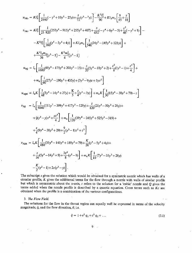
The subscript s gives the solution which would be obtained for a symmetric nozzle which has walls of a circular profile, K gives the additional terms for the flow through a nozzle with walls of similar profile but which is asymmetric about the x-axis, c refers to the solution for a 'cubic' nozzle and Q gives the terms added when the nozzle profile is described by a quartic equation. Cross terms such as Kc are obtained when the profile is a combination of the various configurations.
3. The Flow Field. , The solutions for the flow in the throat region can equally well be expressed in terms of the velocity
magnitude, ~, and the flow direction, 0, i.e.
= l+e2 ql+ ea q2+ ".. (3.1)

0 = [7 + 1] ~: [e 3 01 + e 4 02 + . . . ] (3.2)
where ql, q2, -- . , 01, 02, -. • are known functions of y and z. For instance, the first three terms in the expansions for ~ and 0 are given by
01 ~ /)I
02 ~ /)2
03 = t~a--Ul /)i
and
q. = u . , n = 1,2,3.
Expressions for the local Math number, M, the Prandtl-Meyer angle v and the Mach angle/z can now be obtained from
M = 1+ 2 ql..l_e3 q 2 + e 4 q3_k q +0(e 5) (3.3)
~ r 2 3 v = [ (7+l )qd Lg~ q~+~4q~+
/ lq2 z 9 7 - 5 z'~ +O(e6)] (if4) V
n 1 [- lq'2 2 ~b = ~ - # = [ (7+ l )q l ] ~ Le+~q-~le
flqa l ~ q z ~ 2 +77~411qx)+O(e4) ]. (3.5) e ~q-~ 8 [ q l J
Equations (3.4) and (3.5) are only valid if ql is greater than the rest of the 'q ,s ' because they are initially determined in terms of the small parameter fl, where
f12 = M 2 _ 1
and the expression for fl is obtained from a binomial expansion of
fl = e [ q l +O(e)] ~ (7 + 1)*.
This condition will be satisfied in general, but it will not necessarily hold near the sonic line where ql is small. New functions are therefore defined by
= 42.
(3.6)
(3.7-)
1 0

The series for t /and ~ are
4 a 6 4 2 ~7 r / = ( 7 + l ) -~q18 +~ql q2 +
s / 4 2 4 q~+~q~)+O(e9) ] q3+ q
•
and v and ~b are given by
(3.8)
(3.9)
~b= +X/~.
Negative square roots exist in both cases, and if v and ~b are represented graphically as functions of y and z, the negative square roots give a mirror image of each function with respect to the two axes. These could be regarded as forms of analytic continuation of v and # beyond the sonic line.
4. Special Cases. The expressions for the velocity components are considerably simplified for certain given nozzle
profiles, two of which are discussed here, In the first, the profile is asymmetric about the x-axis only, and the walls are circular, hyperbolic or parabolic arcs. The Second nozzle has a cubic profile and is symmetric about the x-axis. An application of the analysis to a study of the flow in a choked wind tunnel
"is briefly mentioned, with particular reference to the case when a simple symmetric aerofoil is placed in a tunnel of constant cross-section.
4.1. Asymmetry about the x-axis. Since there are no cubic terms present, u z and v2 are zero. The expressions for the velocity magnitude
and flow direction can therefore be writ ten
C/= l + q l a a + q 3 a 4 + . . . (4.1)
0 = (7 + 1)~ [01 ~3 + 0 3 : + . . . ] . (4.2)
Defining
~2Q _ ~ _ 1
and substituting for the 'q,s', the equations of the isobars and of the branchline are determined as
1 2 1 - 2['27 +3 4 . 7 + 3 2 . 2 7 - 1 5 z = -~y +g-Ky+~+~ 1-55-y .q-ff-y + 3--5-g6-+
{ 27+3 2 7 + 3 ' ~ + 2 y - 3 Q Z +e t , - - -g-y +
. . /2~,+3 3 5r+18 2 7 + 3 _ ' ~ + - - V - y - - - 5 - - u y ) +
11

and
T,2/4Y +9 2 47+1 Q'~ +r,_ ~ , T y + ~ + - ~ ) - ~ Y - ] + O ( e * )
z = l y 2 + ~ + K y + K 2 +
(4.4)
2rlo7-9 4- 7 +3 2 .2y--15 L--hs-y --wy
. . ( 1 0 7 - 9 y 3 5y+12y) _ 1 / 1 6 y - 3 2 87+35'~ + ~ , - - - i - 8 - 9 +/~ ~ - - ~ - - Y - 12 ) +
+ * - 3 47-1 , 47 + 9 , : 4 - ]
J (4.5)
Equation (4.4) with Q = 0 is the equation of the sonic line, and its position for various values of K is shown in Fig. 2. The position of the branchline is similarly shown in Fig. 3. For any nozzle, the sonic line and the branchline touch at the singular point where they are perpendicular to the direction of the flow. To a first approximation, equations (4.4) and (4.5) indicate that this point is now at
y = - - g
1 1 2
Hence, it would seem that for large K, e.g., ]K[ > 1, there is no singular point in the real flow. There is, however, a singular point in the continuation of the flow outside the nozzle walls. Consideration of the mapping of the hodograph plane into the physical plane shows that there must be a branchline because the mapping is not single valued. The branchline divides the physical plane into regions such that the mapping from the hodograph plane into each region is single-valued.
The rate of mass flow through the nozzle is only slightly affected by asymmetry about the x-axis. If W* is the rate of mass flow through the nozzle assuming that the sonic line is a straight line across the throat, and Wis the actual rate of mass flow, then
W S 1-1 (pu)~ = ody W* ~L i (p* a*)~ = ody
= s J-t [,~L 2 ~=o dy"
Substituting for fi and Y/,
_ _ 21 ? + 1 2 4 - IU 12 27--3 3 q y-l.g/ ~ = l---~---ule - ( 7 + i ) s 6 tu3+:vi+---~-ul] +0(~81" 2
Thus,
(4.6)
.12

Fig. 4 shows the variation of the reduction in rate of mass flow with K for a fixed value of the mean radius of curvature R. The large reduction indicated for values of K > 1 should be disregarded. When K is greater than unity, the nozzle profile has the shape shown in Fig. 5. The rate of divergence of its cross-section is small for moderate values of the radii of curvature of the walls. However, by fixing a value for R, the rate of divergence is fixed. This value can only be achieved when K > 1 by the wall radii of curvature becoming small, and the theory can not be expected to apply.
4.2. Asymmetry about the y-axis. The nozzle will be assumed to be symmetric about the x-axis and to be described by a cubic profile.
Under these conditions, the expansions for the velocity components for a given value of R contain the single parameter 13. The equations for the isobars and branchline are found to be
_~y2 1 [-1 4 1 2 1 2 1 1 2-] z = +g+Q+ /3Lgy +i-~y -sQy +~Q--~Q j +
+ 2 [ - 2 7 + 3 4 . . 7 + 3 2 2 7 - 1 5 e [ ~ y + ~ - ~ - y + 36---0--
Q/27+3 2 Y+3' - - 7 ) +
+~--~Q2-12 {1~-~(41y6+22y4+6y2+5)-Q(2Oy'~=-lOy2+1)- 2 5 3
Q ( 6 3 y 2 - 5 3 ) - ~ Q } 1 +0(~3) (4.7)
and
1 2 1 el 3 4 2 . z[-107 - 9 4 y + 3 2 . 2 7 - 1 5 z +g+- /g[y - y ----i--~Y -t 360
12 (2y6 + 31y4 + 72yZ_ 5)]~+O(e;). + -Ng (4.8)
The positions of the sonic line and branchline for various values of 13 a re shown in Fig. 6. With increasing la, the sonic line tends to become flatter. This is consistent with a reduction in the rate of area change upstream of the throat; in the limit of infinitesimally slow reduction of area, the sonic line would be a straight line across the throat. The reduction in the relative rate of mass flow through the nozzle should therefore decrease with increasing 13. It is given by
W ,, 4V1 2l 3 2 / 2 ~ + 9 /23 ~ +O(e3) 1 (4.9)
which has the expected variation with 13 ; this is shown in Fig. 6. The velocity distribution along the axis, and the velocity profiles across the flow at z = 0 and z = 0.2
are shown in Figs. 8, 9 a n d 10. The velocity gradient along the axis decreases as 13 is increased, and the velocity profiles across the throat become flatter as did the sonic line. It is apparent from the velocity distributions across the flow at the station downstream of the throat and the velocity gradients along the axis that a positive value of 13 has less effect upon the downstream flow than the corresponding negative value. This is because the flow downstream of the throat is critically dependent upon the rate of increase of cross-sectional area. When 13 is changed from zero to - 2 for instance, the relative change in cross-sectional area at any station downstream of the throat is greater than that obtained when 13 is changed from zero to + 2.
13

4.3. F i o w in a choking wind tunnel.
The analysis of Section 2 can be applied directly to the study of a region of the flow in a choked wind tunnel. If a symmetric biconvex aerofoil of chord c and maximum thickness zc is placed on the centreline of a solid wall wind tunnel of height ho, the flow on either side of the body is that through an asymmetric nozzle given by
K = 1, 13 = m3 = 14 = m4 = . . . = 0.
In a co-ordinate system with the origin at the centre of the body and the x-axis in the downstream direction as in Fig. 11, the surface of the aerofoil is given by
y 2z (x +½c {x +½c}2"~ c = c c = ] . (4.10)
The radius of curvature of the surface at mid-chord is given by
1 ( d 2 y ) 4z (4.11) R-~ = \~x2 ]o - c
the non-dimensional radius of curvature corresponding to that' used in the previous sections is thus
R = ~ ( h o - z C ) - z--ho h o ] (4.12)
Some experimental results are given by Spreiter et a111 for both two-dimensional and axially-symmetric choking flows. Since the radii of curvature of the two-dimensional aerofoils were small, the corresponding theoretical solution for the flow will not converge quickly. In the axially-symmetric case the bodies of revolution have larger radii of curvature and are more suitable for comparison with the present theory 8.
5. The Inverse Problem.
The inverse problem is that of calculating the shape of nozzle which will produce a given distribution of velocity along some line in the flow. This line will be taken to be the x-axis. Taking the origin to be the sonic point on "the axis and assuming that the flow direction is along the x-axis at this point, the velocity distribution may be assumed to have the form
u(O,x) a* = 1 + b'l (x + b'2x 2 + b'ax 3 + . . . ) (5.1)
v(O,x) a* - c'1 x + e'2x 2 + c'3x a + . . . (5.2)
where the 'b',s" and "c',s" are constants. In most of the solutions previously obtained 6 9 the given velocity distribution has been restricted to the case where b', = 0 for n > 1, c', = 0. The velocity components were then sought as double power series in x and y. With such a restriction on the shape of the velocity distribution, it would seem inconsistent to evaluate the series for the nozzle shape to include terms of high order, i.e. terms containing xmy ~ with (m+ n) large. A more logical approach would be to seek a solution for a general velocity distribution of the form shown in equations (5.1) and (5.2).
A further criticism of these previous solutions is that the order of the neglected terms is not known. Consequently, although the solutions must be applicable in some region close to the Origin, it is not clear how large this region is. In the solution derived below, the terms are collected together in groups,
14
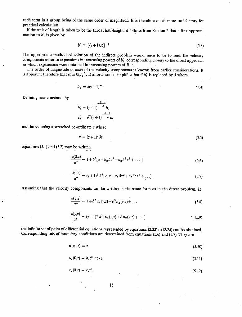
each term in a group being of the same order of magnitude. It is therefore much more satisfactory for practical calculation.
If the unit o f length is taken to be the throat half-height, it follows from Section 2 that a first approxi- mation to b] is given by
b] ~ [-(y+ 1)R] -~ (5.3)
The appropriate method of solution of the indirect problem would seem to be to seek the velocity components as series expansions in increasing powers of b~, corresponding closely to the direct approach in which expansions were obtained in increasing powers of R -~.
The order of magnitude of each of the velocity components is known from earlier considerations. It is apparent therefore that c', is 0(b~2). It affords some simplification if b~ is replaced by 6 Where
b~ = 6(?+ 1) -/~ '5.4)
Defining new constants by n-1
b~, = (y+ l ) 2 b. n--1
Cn 62 0~-{- 1) 2 Cn
and introducing a stretched co-ordinate z where
x = ( r + i ) ~ & (5.5)
equations (5.1) and (5.2) may be written
u(O,z) - 1 + 52[z+ b 25z 2 + b 362z 3 + . . . ] (5.6) a*
v(0,z) a* - (~ + 1)~ 63 [c l z + c25z 2 + c362z a + . . . ] . (5.7)
Assuming that the velocity components can be written in the same form as in the direct problem, i.e.
u(y,z) = 1 + 62 u l (y,z) + 5a u2 (y,z) + (5.8) a* " '"
v(y,z) a* - (? + 1)~ 63 Iv1 (y,z) + 6 v 2 (y,z) +. . . ] (5.9)
the infinite set of pairs of differential equations represented by equations (2.23) to (2.25) can be obtained~ Corresponding sets of boundary conditions are determined from equations (5.6) and (5.7). They are
ul(O,z ) z (5.10)
u,(O,z) = b,z" n > l (5.11)
v,(O,z) = c,z". (5.12)
I5

Solving each pair of differential equations subject to the boundary conditions using a method similar to that employed in the previous sections gives the solutions to the velocity components as: 1st approximation
ul = ½y2 +clY+ Z
~ = ~y~ +½q y~ +(y+ ci)~.
7 (~ 1 )ya+z(3b2y2+2c2y)+bzzZ u2 = ~bzY'*+ c2+-~b2cl
V 2 = b2y5+ c2+~b2c y "-k~CtCzY 3
['7 b 3 + ~ 5 ~ y + {2~+b~ ~dy~)+z ~ (3b2 Y+C2)
3rd approximatior~
U 3 ~--- (~2 1 23 z\ 1 3 2
(5 1 ) 4 @ + 1 4 2 z 327+3 y3+c~y2+ + -gb2c2+~qc3 y +--N-y +~c2y +--T-c1
F(I .) 3 2 (b3cl+3Ca+~b2c2) y a + ~ _ y
l +2b2 c2 y2 +z 2 [(6ba+3b~)y2+3c3 y]+b3 z 3
/ ' 7 1 7 5 0 (1~0 1 3 9 1 9 .L-~ba+~4-dc3+~b f + b3q+~cac~+]~-dc3+i-~b2c2+
35 1) (1 2 7 4 3 2) s 18y-1 s +~b~c y6_[_ gb.3cl+~clc3+~b2clc2._b~b2 c y q _ ~ y ..]_
(2 1 ~) 4.143'+5 4.23'+32 a. + ~b2clc2+~c y + ~ c l y + ~ - - c l y +
7 +~b2 z C l ) y 4 q - [(5ba+3ca+2@bZ) y _i_ (~ b 3 9 5 "q-Z (71 - t -~ C 3 - t -~ b 2 c 2
• 63'+ 1' 3 . 23,+3 Yl -t-(3b2c2+2ClC3) ya-t----~ y -t--~-~-cl yZ-l-2cZ y2.-t-2c~ +
[ ( ~ 2z ) (3 9 2) +z 2 b3+3c3+6 b y3+ ~b3cl+~ca+2b2c yZ+
+~-y+2b2c2y ] +z 3 [4b3y+2bZzy+c3] •
(5.13)
(5.14)
(5.15)
(5.16)
(5.17)
(5.18)
16

In the most general case this leads to an asymmetric nozzle, non-zero "c,s" corresponding to non-zero K and "m,s' in the direct solution. The remainder of this section will be devoted to the general symmetric case, general in the sense that all the "b,s' are non-zero.
In a symmetric nozzle, all the 'e,s, are zero and the position of the throat can be determined by calculat- ing the value ofz which gives zero transverse velocity at the throat half-height. In this instance, the throat half-height is unity. Hence
a,--~ - = -~+6 - ~ b 2 + s b 2 z + 3 b 2 z +
5_ 2 18y-1 5 b3 +-~bz z + - ~
+z2 {l--~32b3+6b!+~-} +z3 {4b3+2b~}) ] (5.19)
Writing
Zthroa t = Z0 .~ 6Z 1 ..]_ ~2 Z2 _jr . . . . (5.20)
substituting in equation (5.19) and equating coefficients of equal powers of 6 determines the constants z,. The first three are
1 z0 = - g (5.21)
1 zl = - ~ b2 (5.22)
2 y - 9 2 b3 (5.23) z2 = ~ 18
The streamlines are given by
dy v d-~ = u ' (5.24)
i.e.
1 dy = 6,, Iv1 (y,z) + 6v2 (y,z) + 62 {v3 (Y,Z)- va (y,z) u~ (y,z)} + . . . ] . (5.25) (~+ 1) ~ dz
This equation is a relation between y and z only. The radius of curvature of the streamlines may therefore be determined by differentiation, not ingthat
= : ty) = 0(a,). (5.26)
The radius of curvature of the nozzle, wall (streamline) at the throat is then obtained by substituting the value of throat half-height for y and the corresponding value of Zthroat into the differentiated equation.
17

The radius of curvature, Rt is given by
Writing
(d2y'~ 1 (d2y_'~ Rt 1 = ~ ~X2) throat (]7-{--1) 62 k ~Z2 ) throat
~2 R?* - (7+l,-X(1 +6R1 + 6 2 ) = R2+ .. .)
the values of R 1 and R 2 a r e found to be
(5.27)
(5.28)
4 R1 = g b2 (5.29)
4 . 2 2 . 27+1 R= =
~d3 y~ Expressions may be obtained in a similar way for the 'cubic' term ~ x 3 ]
For instance,
(5.30)
and higher order terms.
6 2 13 - (7 + 1~ [6b2 + 6(9ba + 10b2 z + 27 - 1) + 0(62)]. (5.31)
It is evident that setting bo = 0 for n > 1 imposes a considerable restriction on the solution. The present solution is more satisfactory than earlier ones in which the nozzle shape is sought as a double power series in x and y because thecoefficients of each power of 6 are given as relatively simple closed expressions. It follows that when the series is terminated at any power of bl, the order of the neglected terms is known.
Acknowledgement. The author would like to thank Dr. I. M. Hall for his guidance during the course of the research.
18

a •
A
bl
h,j
h,,,j,,
K
In, mn
R
U~ O~ Ut~ O t
~n
' On
W
W*
x, y
Z
Y
fi
8
0
P
LIST OF PRINCIPAL SYMBOLS
Critical speed of sound
Cross-sectional area of the nozzle
Coefficient of x in the expansion for u(0,x); c.f.'equation (5.1)
Parameters describing the nozzle profile
I)efined by equations (2.10) and (2.11)
Parameter indicating asymmetry about the x-axis
Defined by equations (2.14) and (2.15)
Velocity magnitude
Mean radius of curvature 9f the nozzle walls at the throat; c.f. equation (2.6)
Non-dimensional velocity components defined by equations (2.18) and (2.19)
Coefficient of ~n+ 1 (~n+ 1) in the assumed series expansion for u'
Coemcient of ~n + 2 (~ + 2) in the assumed series expansion for v'
Rate of mass flow through the nozzle
One=dimensional prediction of the rate of mass flow through the nozzle
Two-dimensional Cartesian co-ordinates
Stretched co-ordinate in the x-direction
Ratio of specific heats
Defined by equation (5.4)
R-~
Flow direction relative to the x-axis
Fluid density
19

No. Author(s)
1 F. Frankl . . . .
2 N.C. Freeman ..
3 H. G6rtler . . . .
4 I .M. Hall . . . . . .
5 I .M. Hall and E. P. Sutton . .
6 E. Martensen and .. K. von Sengbusch
7 A. McCabe . . . . . .
8 A .W. Moore and I. M. Hall
9 T. Meyer . . . . . .
10 L. Prandtl . . . . . .
11 J. R. Spreiter, D. W. Smith and B. J. Hyett . . . . . .
REFERENCES
~tle, etc.
On two-dimensional airflows in channels neighbourhood of the velocity of sound.
Rec. Math. Moscou, 40, 1, p.99, 1933.
at velocities in the
•. Private communication.
The transition from subsonic to supersonic velocity in a gas flowing through a nozzle.
~eit. angew. Math. Mech. 19, pp.325-337, 1939.
Transonic flow in two-dimensional and axially-symmetric nozzles. Q.V.R. Mech appl. Math. XV, 1962.
Transonic flow in ducts and nozzles; a survey. Symposium Transsonicum, Aachen, September,
Verla 9. 1964. Springer-
Numerische Darstellung yon ebenen und rotationssymmetrischen transsonischen Diisenstr6mungen mit gekriimmtem Schalldurch-
gang. Mitt. Max Planck Inst., No. 19, 1958.
Design of a supersonic nozzle. A.R.C.R. & M. 3440, March 1964.
Transonic flow in the throat region of an annular nozzle with an arbitrary smooth profile.
A.R.C.R. & M. 3480, January 1965.
Uber zweidimensionale Bewegungsvorg/inge in einem Gas, das mit Uberschallgeschwindigkeit str6mt.
Forschungsheft, VDI 62, 1908.
Str6mende Bewegung der Gase und Dampfe. Enzyklop~idie der mathematischen. Wissenschaften V, 56, p.287; Gesammelte Abhandlungen 2, p.905,
1905.
A study of the simulation of flow with free-stream Mach No. 1 in a choked wind tunnel.
NASA TR R-73, 1960•
20

FIG. i.
R
X
The throat region of an asymmetric nozzle.
0-8
0-4
0
- 0 . 4
- 0 - B
- I .Z
I
m
m
O
K
0 0.25
13 0.50
,~ 0.75
A I "00
l> I "50
R----10
I I I I
I I I I - I - Z - 0 - 8 - 0 - 4 0
I 0"4
FIG. 2. The position of the sonic line.
0.8 ~ I-Z
21

Y
0.4
-0"4
- 0 . 8
-- l '2
I I I I I I I I t I
[ i I I ; I t I 0-4 0"8 1"2 i '6 2-0 ;)-4 2-8 3-2 3-6 ~ 4-0
FIc. 3. The position of the branchline.
| -w/wtt x J03
u
t# ,u
J
I I
J Rml0
I I I I I I 0-25 0.50 0"/5 1.00 1.25 1.50
Parameter K
F]6. 4. The variation with K of the rate of mass flow through the nozzle.
22

X
fill i
FIG. 5. The nozzle profile when k> ' l .
o.,1
o.4 0.Z i..--
0
O
0
A
R
I I I I I
./-3 Z.O 0
-Z.O = 5
Sonic line
Brclnchiin¢- ~tS i/~
' ~/~i~ "~i~'~j~Pt -
I I I ~ I I -0"08 0 O'O'E 0;i 6 0.Z4 0.32
FIG. 6. The positions of the sonic line and branchline in a 'cubic' nozzle.
0"40
23

2.o I I I I I
i_W/w ~ 1.6
x 10 3 "~ 1.2
~ 0 . 8
~ 0 ' 4
o I I I I -2 - I 0 I 2
Parameter /3
FIG. 7. The variation with 13 of the rate of mass flow through the nozzle.
I I I I I I 1"05
N 13:
+ f%l
¢%1
4-
4.
1.00
0-95
0.90
o 2 o 0 r, -Z
R=~5
0.85 1 - 0 ' 4
FIG. 8.
I I 1 I - 0 . 2 0 0.2 .~. 0.4
The velocity distribution along the axis of a 'cubic ~ nozzle.
24

I i I 1.0
Y
0.~,
0.6.
0.4
0.2
o 2
o 0
-2
R = 5
0 0.96 0'%
FIG. 9.
I I I I I'00 1.02 1.04 1.06
I ÷ Ul/R ÷ UZll:t312 + U31R z
The velocity distr ibution across the throat.
I.O'b
I I I I 1 1.0.
Y
0-~
0 .6
0.4
0"2
13 D 2 o 0
P , - 5
0 1.00
FIG. 10.
I I I I I.OZ 1.04 1.06 1"08 1.10 I ' lZ
/
i + U l l R + UZlN31Z + u 3 / R Z
The velocity distr ibution across the flow at z = 0"2.
25

Y
• g/!h
C ~
F.Io. 11. The co-ordinate system for an aerofoil in a choking wind tunnel.
• Printed in Wales for Her Majesty's Stationery Office by Aliens (Wales) Limited
Dd.[25874 K5 3/67

R, & M . No . 3481
© Crown copyright 1967
Published by HER MAJESTY'S STATIONERY OFFICE
To be purchased from 49 High Holborn, London w.c. I 423 Oxford Street, London w. 1
13A Castle Street, Edinburgh 2 109 St. Mary Street, Cardiff
Brazennose Street, Manchester 2 50 Fairfax Street, Bristol 1
35 Smallbrook, Ringway, Birmingham 5 7-11 Linenhall Street, Belfast 2
or through any bookseller
[
~. & M° No. 3481
S.O. C o d e N o . 2 3 - 3 4 8 1