Embed Size (px)
Citation preview

1
The Unique Cosworth Story
The help of Michael Costin in this section is gratefully acknowledged.
Any remaining errors are the author’s responsibility.
Eg 47 1968 Cosworth DFV 2987cc; 415 HP @ 9,500 RPM (see linked Note 75B)
Eg 62 1982D Cosworth DFV - Judd; 2987cc; 515 HP @ 11,300 RPM
The Cosworth DFV ('Double Four Valve') Grand Prix engine was unique in three areas:-
• Racing successes • Value-for-purchasers' money • Commercial return to its makers.
It is unlikely ever to be surpassed in any of these ways.
Over 16½ years, from a victorious June 1967 debut to the end of 1983, without change of bore
and stroke or major castings, it powered nine men who won 12 Drivers' Championships* and five
chassis makers who won 10 Constructors' Championships**. It won for its users 154 classic
Grand Prix victories, 65% of the possible, competing against 10 other major engine makes with
30 substantially different specifications (see Note 75, linked).
The 3L normally-aspirated DFV was only displaced eventually by TurboCharged (TC)
engines of 1.5L (the alternative regulation limit for pressure-charging), although a respectable
argument existed that pressure-charging by that method breached a basic rule that only one
engine per car was permitted (see Note 76 ). The TC engines required five years of
development in the Grand Prix application before they conquered the DFV finally in 1983 to win
both Championships.
For ease of study these 16½ years are treated together and the Ferrari engines which
interrupted the DFV's successes will be described later.
* G Hill, Stewart (3 times), Rindt, Fittipaldi (2 times), Hunt, Andretti, Jones, Piquet, Rosberg.
The first and last Championships are listed in the heading above and in later details an Eg number
indicates both Championships were DFV-powered except where shown as D for Drivers' only
(1976 and 1982).
** Lotus (5 times), Matra, Tyrrell, McLaren, Williams (2 times).
Foundation of Cosworth Engineering
It is worth giving a brief history of Cosworth Engineering prior to the DFV since its
subsequent achievements were so unusual. Ref (60) gives biographies of the four men who were
the principals in the creation of the DFV. The founders of the company in October 1958 were
Keith Duckworth and Mike Costin who, by 1965, took the roles of Designer and Developer
respectively, with support on the business side from Bill Brown and in manufacturing from
Ben Rood. There was overlap in this quite informal group, which came together by chance
through their shared enthusiasm for motor racing. Duckworth had a degree in Mechanical
Engineering, the others were practical engineering men, Costin having trained with de Havilland
Aircraft. The firm began as a very small engine tuning workshop but Duckworth, unlike many
others who set up in that business, very soon took the relatively high risk of borrowing £600
(£12,000 at 2013 level) to buy a dynamometer - a characteristic determination to do the job in a
fundamental way (Note 77). At first Cosworth tuned 1,100cc Coventry Climax engines for Elva
sports cars. A major step forward and financial salvation came at the end of 1959 when
Duckworth adapted for the new (in the UK) Formula Junior the recently-launched Ford 'New
Anglia' 105E engine, an 8-port IL4 1.0L with the remarkable B/S of 3 3/16" (80,96mm) /
1 29/32" (48.42) = 1.67, although with PR OHV. It had a 3-main-bearing crank. From the 39 HP
(DIN) of the stock unit the Cosworth FJ power was raised to 75 HP (SAE-type) by using
individual, tuned inlet and exhaust systems and a long period (ca 320°) camshaft. In the very
effective mid-engined Lotus 18 chassis and later derivatives (see Note 66), this FJ engine was
47% successful in the four years of the formula 1960-1963, sweeping aside the front-(tuned-
Fiat)-engined Italian cars which had predominated in 1959.

2
By 1963, enlarged to 1.1L (allowed at higher car weight) and built experimentally with 50°
downdraught inlet ports it was producing 120 HP. In the same year the Ford basis was continued
when Duckworth designed for the forthcoming 1964 F2 1.0L formula a new SOHC head (raising
RPM above the PROHV limit) to suit their ‘Cortina’ 116E 1.5L 5-main-bearing cylinder block
with the same 3 3/16" Bore but 105E Stroke via a special crankshaft. Walter Hayes, Public
Affairs and Competitions Director of Ford of Britain, provided £17,500 (60) (£310,000 at 2013
level) to support the manufacture of this SCA engine ('Single Camshaft type A'), which also had
50° downdraught inlet ports. Over 1964-1965 in F2, developed to 140 HP in the second year
with fuel injection (see Note 73) it won 81% of its races against BRM and Honda opposition,
although then outmatched by the redesigned 4v/c DOHC Honda in 1966 when Cosworth were
concentrating on their next steps.
Inception of the Cosworth FVA and DFV
Colin Chapman of Lotus, after having been told by Coventry Climax in early 1965 that they
would not produce a 3L Grand Prix engine for the new formula starting in 1966 and after
considering his successes with Cosworth-Ford FJ, F3 and F2 engines, decided very quickly
that Duckworth was the man to design and Cosworth the firm to make the power unit he
needed. Development money was the problem. However, after some abortive appeals
elsewhere, Chapman was able to persuade Walter Hayes and his colleague Harley Copp,
Vice-President of Engineering at Ford of Britain, to propose to their Policy Committee
(chaired by Stanley Gillen, Managing Director) and get accepted a £100,000 (£1.6M at 2013
level) payment to Cosworth to design, develop and produce engines for each of the upcoming
1967 1.6L F2 category and then the 3L Grand Prix formula (60). This agreement was reached
in October 1965.
In detail, one-quarter of the sum was to go to the F2 FVA engine (‘Four Valve type A’) with a
4v/c DOHC head on the Ford 'Cortina' 120E 1.6L block, which Duckworth was already
designing. If that was sufficiently powerful, the balance would be used for a V8 3L using the
same head type. The GP engine was to be ready by May 1967 (ie the second season of the
new formula) and a separate Ford Letter of Intent covered its supply free of charge to Lotus
(60). Both engine types were to carry the Ford name.
While cautious concerning the ‘top end’, at Duckworth’s request, the fact that he had not then
designed from scratch the ‘bottom end’ of any engine meant that these arrangements for the
V8 represented great confidence by Ford in his and Cosworth’s fundamental engineering
abilities.
The technical advances of the Cosworth FVA
The background to the ‘Four-Valve Renaissance’ (as the late Brian Lovell described it) is
given in Note 78. The FVA is examined here in detail, although not a Grand Prix engine,
because of its importance to the unprecedented DFV success. Keith Duckworth revealed a
good deal of his design philosophy - but certainly not all! - in early 1971 in ref (60).
The step forward in performance of the 4v/c DOHC 1.6L type FVA, designed by Keith
Duckworth from July 1965, with a first bench test in March 1966 and first race during
development in a small club event in July 1966 (247)*, can be measured by comparison with
the 1961 2v/c DOHC Coventry Climax FPF 1.5L Mk 2, also an IL4. The full details are given
in Note 79 (linked). The FVA delivered 38% more HP per unit of swept volume (PP/V) by
generating 15% higher BMEP at 17% higher piston speed (coupled with a 3% shorter stroke)
at a similar weight and similar Price/HP. After four years of development the 1970 FVA
improvements on these three performance factors were 49%, 17% and 23% respectively.
As another index of the advance achieved by the 1967 1.6L FVA it can be compared with the
highly-developed 1965 GP Championship-winning Climax FWMV Mk 6 1.5L, which was a
* As the FVB, having a short-stroke crank to give 1.5L, this being an experimental check on the block
power which would be obtainable in the V8.

3
600 VIA 4v/c DOHC design. This had the basic PP/V advantage of being a V8 with a stroke
only two-thirds of the FVA but was only 2% higher on that performance factor in an engine
weighing 14% more, sold at 2 x the price. The developed 1970 FVA had a 6% PP/V
advantage over the 1965 Climax, reaching 150 HP/L.
These gains sprang from the cylinder head/piston design changes in the FVA, which can be
summarised as follows.
4v/c v 2v/c
1. In engines whose valve operating gear is geometrically similar a 4v/c design with the
same total IVA as a 2v/c can run √2 (41%) higher N at the same spring stress. This is
because IVL is 1/√2 smaller so MVS is the same. However, in the FVA compared to
the FPF, although IVA/PA was very alike (about 0.3) there was not much similarity
overall. This was:-
firstly, because IOD was 10.3% longer (320° v 290);
secondly, because IVL was only 1.9% smaller (10.2mm v 10.4)
The net effect on MVSP at an achieved NP 20% higher was +6.5%, tolerable for
spring wire available six years later.
The reason for the relatively high IVL, ie IVL/IVD = 0.3 v 0.23, was to
facilitate ‘Barrel Turbulence’ in the cylinder (explained below; this is Cosworth’s
preferred description, although it is described elsewhere as ‘Tumble Swirl’).
The longer IOD of the FVA was not prejudicial to the 'driveability factor' (NP-
NT)/NP, which was 22%, where the FPF 1.5L Mk 2 was probably about 17%.
2. Lower VIA at the same IVA/PA and same R, because the four valve heads can be
fitted into the bore without needing any lateral inclination at all to provide IVA/PA
=0.3, which is near the optimum for an engine with individual, tuned inlet and
exhaust. systems (see Note 34). The FVA VIA = 40° was mainly to provide access
to an optimum central position for the single sparking plug.
This lower VIA in a high-R engine eliminates the need for a high-crowned piston
top and so reduces the Surface Area/Volume ratio of the combustion chamber,
thereby raising Combustion Efficiency (EC). With 4v/c and a nearly flat piston top*
it was simple to provide segmental squish plateaux in the head on either side of the
valve pairs, to delay detonation to higher R.
* Except for pockets to clear the part-open valves at exhaust Top Dead Centre.
3. Compared with a high VIA design at high R, the flat piston top of the low VIA
engine reduces the piston mass and the heat flow into the crown, so that piston
stress and temperature at a given N are lower - or, for a required life, N can be
higher.
Advantages 1, and 3, can be optimised by the choice of B/S ratio. In the FVA case, B/S was
set by the maximum bore possible within the F2-rule-necessitated production block selected.
Inlet downdraught
After finding the advantage of 50° downdraught (dd) to the vertical inlet valves of the
developed FJ and the SCA engines, via reduced inflow turning loss, Duckworth was still able

4
to use 30° dd on the FVA although the inlet valve was inclined at 20° from the vertical. The FPF, with 33° valve inclination, had only 12° dd. ‘Barrel Turbulence’
The advantages of ‘Barrel Turbulence’, where the inlet flow is aimed at the opposite cylinder wall so as to produce a circular motion in the plane of crankshaft rotation which is then much amplified in velocity by the rising piston during compression, are discussed in Note 26*. It produces a gain of the product Volumetric Efficiency (EV) x Combustion Efficiency (EC), the first element being reduced by the extra pressure loss to produce the swirl but the second element more than compensating for this through faster burning. It is believed that Barrel Turbulence was the most important feature in producing the superior FVA performance (see Note 80).
Mechanical design of the FVA
A cross-section of the FVA is given on Figure 47A.
The mechanical details of the FVA were mostly conventional for the period, bearing in mind the required use of the Ford 120E cast-iron cylinder block. A novelty found essential in the SCA was repeated, being a small diameter quill between the crank nose and the base gear of the camshaft drive train to cushion the system from crankshaft vibrations (maximum controlled oscillation ± 2°. Woods-type tappets were used, ie placed above the springs so that these could be oil-cooled efficiently, MVS being 3.4 m/s, typical for the coil spring materials of the time. Valve timing was 'standard' Cosworth: 58/82 // 82/58. Lucas port-type fuel injection was fitted, the shuttle stroke in the distributor now controlled by a cam rotated by the throttle linkage so that fuel flow could be better matched to the engine requirement. Ignition was by Lucas transistorised system. Advantage was taken of the narrow VIA to use a one-piece valve gear cover with plug wells, as on the contemporaneous Eagle-Weslake 4v/c VIA = 30° design. Surprisingly, the pistons were full-skirted except for small reliefs either side of the gudgeon pins (the SCA were slipper-type). A Dykes-type top compression ring was employed to permit MPDP = 4000g. The exhaust system was 4-into-2-into-l, respectively 15", 15" and a plain tail pipe 30" long ((191) for the later DFV) - this projected well beyond the normal rear of the cars in which the FVA was installed, where rules limited such projections to 250mm (10"), so tubular 'bumpers' were added later to the gearboxes to 'fake' the car length! Clearly the tail pipe length was important to performance or it would have been shortened.
FVA success and imitation
The Cosworth FVA provided the power to dominate the 1.6L production block, maximum six cylinders, F2 Championships of 1967 to 1971 (excluding 1970), obtaining 78% of possible wins in those five years against V6 Ferrari type 166 and IL4 BMW M12/2 competition. The 1972 Championship, to new 1972-1975 2L rules based on production block and head, was won in a car powered by a Ford Cosworth BDA-base engine, a 'productionised' FVA with belt drive to the DOHC ('Belt Drive type A') developed for racing by Brian Hart at 1.85L.
Imitation being the sincerest form of flattery, BMW bought an FVA and adapted its head/ piston design to its own block for its 1973 IL4 M12/6 2L F2 engine (605) and proceeded then to win the Championships in 1973-1975 inclusive. It won another three Championships during the 1976-1984 F2 formula, which permitted full racing engines up to 2L and six
(Continued on page 7) _____________________
* Some sources separate “Tumble”, as being a circular charge flow motion in the plane of the
crankshaft rotation, from “Swirl” as motion in the plane of the cylinder bore.

5
Figure 47 A Representing Eg. 47
1967 Cosworth FVA
IL4 B/S = 3.375”/2.722” = 85.725mm/69.139mm = 1.24 1596cc
The carry-over of FVA design features to the DFV is described in detail in the main text.
DASO 583

6
POWER CURVES
Eg. Basis of Eg.47
DASO 583
YEAR 1966
Make Cosworth
Model FVA
Vcc 1596
Ind. System NA
Confign. IL4
Bmm 85.725 (3.375") (3 3/8")
Smm 69.139 (2.722")
N P MPS BMEP
kRPM HP m/s Bar
6.5 164 14.98 14.15
7 181 16.13 14.50
8 206 18.44 14.44
8.5 217 19.59 14.31
8.75 221 20.17 14.16
9 222 20.74 13.83
9.25 220 21.32 13.34
9.5 214 21.89 12.63
7
cylinders. Destroked to 1.5L and turbocharged as the M12/13 for Grand Prix, this BMW engine, based originally on Cosworth FVA technology, appears later in this review as the power of the 1983 Drivers' Championship, the first TC engine to achieve this.
The DFV design
A cut-away drawing of the original DFV is given on Figure 47B.
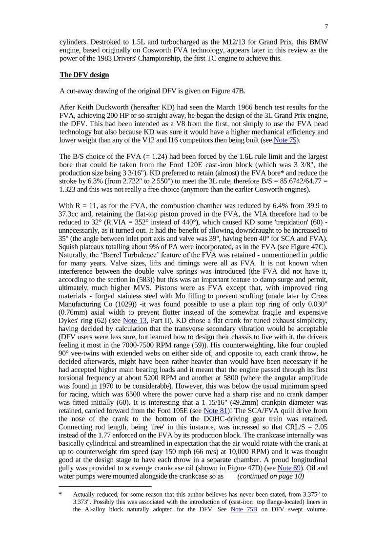
After Keith Duckworth (hereafter KD) had seen the March 1966 bench test results for the FVA, achieving 200 HP or so straight away, he began the design of the 3L Grand Prix engine, the DFV. This had been intended as a V8 from the first, not simply to use the FVA head technology but also because KD was sure it would have a higher mechanical efficiency and lower weight than any of the V12 and I16 competitors then being built (see Note 75).
The B/S choice of the FVA (= 1.24) had been forced by the 1.6L rule limit and the largest bore that could be taken from the Ford 120E cast-iron block (which was 3 3/8", the production size being 3 3/16"). KD preferred to retain (almost) the FVA bore* and reduce the stroke by 6.3% (from 2.722" to 2.550") to meet the 3L rule, therefore B/S = 85.6742/64.77 = 1.323 and this was not really a free choice (anymore than the earlier Cosworth engines).
With R = 11, as for the FVA, the combustion chamber was reduced by 6.4% from 39.9 to 37.3cc and, retaining the flat-top piston proved in the FVA, the VIA therefore had to be reduced to 32° (R.VIA = 352° instead of 440°), which caused KD some 'trepidation' (60) -unnecessarily, as it turned out. It had the benefit of allowing downdraught to be increased to 35° (the angle between inlet port axis and valve was 39°, having been 40° for SCA and FVA). Squish plateaux totalling about 9% of PA were incorporated, as in the FVA (see Figure 47C). Naturally, the ‘Barrel Turbulence’ feature of the FVA was retained - unmentioned in public for many years. Valve sizes, lifts and timings were all as FVA. It is not known when interference between the double valve springs was introduced (the FVA did not have it, according to the section in (583)) but this was an important feature to damp surge and permit, ultimately, much higher MVS. Pistons were as FVA except that, with improved ring materials - forged stainless steel with Mo filling to prevent scuffing (made later by Cross Manufacturing Co (1029)) -it was found possible to use a plain top ring of only 0.030" (0.76mm) axial width to prevent flutter instead of the somewhat fragile and expensive Dykes' ring (62) (see Note 13, Part II). KD chose a flat crank for tuned exhaust simplicity, having decided by calculation that the transverse secondary vibration would be acceptable (DFV users were less sure, but learned how to design their chassis to live with it, the drivers feeling it most in the 7000-7500 RPM range (59)). His counterweighting, like four coupled 90° vee-twins with extended webs on either side of, and opposite to, each crank throw, he decided afterwards, might have been rather heavier than would have been necessary if he had accepted higher main bearing loads and it meant that the engine passed through its first torsional frequency at about 5200 RPM and another at 5800 (where the angular amplitude was found in 1970 to be considerable). However, this was below the usual minimum speed for racing, which was 6500 where the power curve had a sharp rise and no crank damper was fitted initially (60). It is interesting that a 1 15/16" (49.2mm) crankpin diameter was retained, carried forward from the Ford 105E (see Note 81)! The SCA/FVA quill drive from the nose of the crank to the bottom of the DOHC-driving gear train was retained. Connecting rod length, being 'free' in this instance, was increased so that CRL/S = 2.05 instead of the 1.77 enforced on the FVA by its production block. The crankcase internally was basically cylindrical and streamlined in expectation that the air would rotate with the crank at up to counterweight rim speed (say 150 mph (66 m/s) at 10,000 RPM) and it was thought good at the design stage to have each throw in a separate chamber. A proud longitudinal gully was provided to scavenge crankcase oil (shown in Figure 47D) (see Note 69). Oil and water pumps were mounted alongside the crankcase so as (continued on page 10)
* Actually reduced, for some reason that this author believes has never been stated, from 3.375" to
3.373". Possibly this was associated with the introduction of (cast-iron top flange-located) liners in
the Al-alloy block naturally adopted for the DFV. See Note 75B on DFV swept volume.

8
Figure 47B
1967 Cosworth DFV
90V8 B/S = 3.373’’/2.550” = 85.6742mm/64.77mm = 1.323 2987cc
DASO 175
Drawing by Vic Berris

9
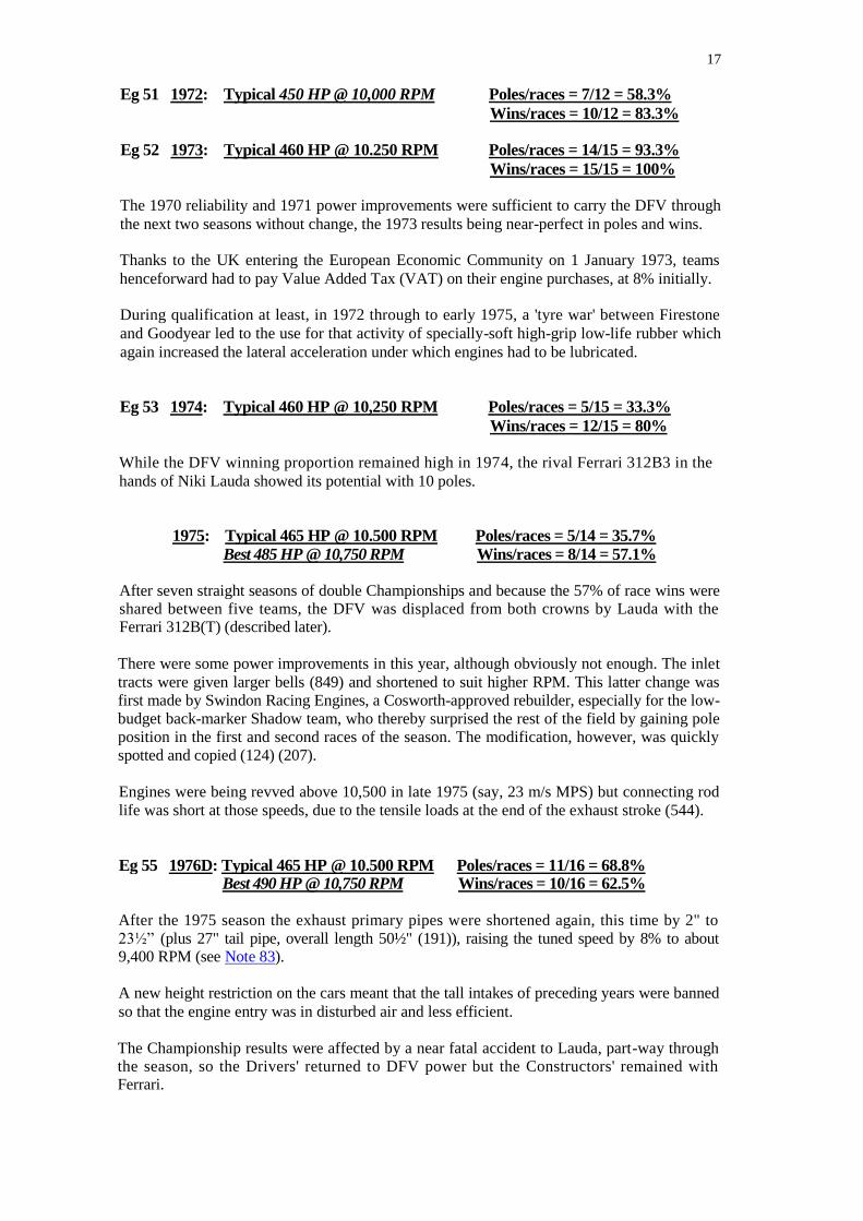
Figure 47C Representing Eg. 47
1978 Cosworth DFX
90V8 85.6742/57.3024=1.495 2643cc
The DFX Indycar engine had the same basic cylinder head as the DFV. This 1978 section shows:-
• The 1.36" IVD introduced in 1978; • The 20% necked inlet valve stem introduced in 1971.
As drawn the inner valve springs do not show interference with the outer. (The exhaust valve stem of the DFX was probably thicker than the DFV, with
Na-cooling.) DASO191
Figure 47D
1967 Cosworth DFV
Showing the gully provided to pick up scavenge oil, recognising
the flow direction enforced by crankshaft windage. Note that this feature was also used in the FVA, see Fig. 47A. OIL COLLECTION GULLEY
The drawing also shows the separate compartments for each crank throw
DASO 175

10
to keep the overall length short, driven from a pulley on the DOHC train via an internally-
toothed fibreglass-reinforced rubber belt - a novelty. The clutch was a new AP unit
with a Cosworth 7.25” (184mm) diameter twin -plate driven assembly.
As on the FVA, the by-now-conventional Lucas port injection system was fitted but with a mechanically-driven, instead of the previous electrically-driven, pump to provide the 100 psi supply to the shuttle. The new Lucas Oscillating Pick-Up System (OPUS) ignition was soon applied, since this gave a better low RPM spark which permitted a smaller, 2.7 kg lighter, starter motor. For the second time on a GP engine much needed protection against overspeed was provided, in this case electrically rather than mechanically as on the 1954 M196, with a governor to fade out the ignition over 160 RPM towards a preset limit, avoiding an abrupt cut, and feeding-in similarly. Of course, this system only helped on acceleration since the engine could still be oversped by a premature downwards gear change (see Note 82).
An early decision had been to improve chassis stiffness (and also save car weight) by using the engine as the sole structural connection between the middle and the rear suspension of the Lotus 49 chassis being designed in parallel, and the static parts were designed to accept the resulting loads without unacceptable distortion. Material flexure was permitted at the top two of the four front mountings in the direction of the cylinder axes, to absorb thermal expansion. Many previous cars had used the engine to stiffen the chassis, as far back as the 1902 Panhard and especially in the GP Bugattis; the Lancia D50 used it to replace the top tubes of a space frame and BRM had pioneered the engine as sole connection with their I16, followed naturally by the Lotus 43 with the same engine.
The DFV V8 3L was a compact engine, very helpful to mid-engine mounting - its length (excluding clutch) was only 6.4B (21.6"/3.373") (191) whereas, eg the original Climax FWMV V8 1.5L of six years earlier was basically 8.7B (21.5"/2.48") (34) (although later this accommodated a 2.85" bore, ie length = 7.5B). Beyond this, the FWMV water and oil pumps projected a further 2.6" at the front, where the DFV's were mounted alongside the block so as to give a clear joint with the Lotus 49 monocoque (a placement of the pumps followed by most later engines).
The exhaust system was the same as on the FVA (ie 4-2-1) 60" (1.52 m) overall and the L49 was later fitted with the same rear bumper addition as the F2 cars for the same ‘regs. dodging’ reason. It is interesting that the primary pipe diameter chosen for the DFV gave a geometrical expansion ratio from the twin exhaust ports of about 1.7 after an equivalent conical diffuser angle of 6°. The primary-plus-secondary pipe lengths (15" + 15" (0.76m)) are estimated to have been tuned to about 7,500 RPM (see Note 83).
The DFV design work, entirely by KD (at home away from factory distractions) with Mike Hall (formerly of BRM) drawing the side accessories from KD’s schemes, was completed in only nine months, ie by about the end of 1966. Duckworth later opined that this was because he then had the optimum amount of necessary knowledge, where later he would have tended to design-out possible problems which, if they had occurred in running, could have been solved quickly (59). The first engine ran in April 1967 and the first delivery to Lotus was later that month, meeting the Ford contract signed 18 months earlier.
Duckworth insisted that the DFVs should be returned to the works for overhaul and repair,
even when sold to customers after 1967, and this supply stipulation remained in force until
the end of 1970. The number of engines involved was then too great for Cosworth to manage
them all and they, therefore, approved certain outside firms to do some of this work, using
genuine Cosworth spares of course (866). At one time engines carried a label on which
mileage was to be stated when returned, plus the crisp comment (undoubtedly due to KD) that
"It is better to be un-informed than ill-informed" (vide the display unit in the Donington
Collection)!

11
1966 DFV materials
Cylinder heads ) Al-alloy LM25WP. Cast. Cylinder block )
Crankshaft En40B Nitrided. Forged.
Connecting rods En 24. Forged.
Cylinder liners Cast iron.
Pistons Al-alloy RR58. Forged.
Piston rings Top: Mo-filled stainless steel. Forged.
Big-end and main bearings Plain Vandervell VP2, copper-lead with Indium
flashing.
Camshafts Monikrom chill-cast nickel-iron.
Cam carriers Al-alloy LM25WP. Cast.
Valve-gear covers Mg-alloy
Valve springs Not known
Timing-gear wheels Not known
Inlet valves Not known
Exhaust valves 21-4NS+0.2% Columbium.
Tappets EN16T Tufftrided.
Oil pressure and scavenge pumps Internally-toothed belt of rubber with glass fibre and water pump drives tension reinforcement.
The DFV through the years
The fullest known history is given for the DFV, including the years in which it did not secure Championships. Tabulated performance, weight and price details are provided in Note 84 (now linked).
1967: 405 HP @ 9,000 RPM Poles/races = 9/9 = 100%
Wins/races = 4/9 = 44.4%
If the DFV on its first and victorious appearance (at the Dutch GP in June 1967 powering the Lotus 49) had produced the same BMPP and MPSP as the 1967 FVA, ie PP pro rata with PA, it would have developed 440 HP @ 9,600 RPM. In fact, because of a resonance in the valve gear which broke cam driving gear teeth early in the bench tests (59) starting in April 1967, the engine had to be limited by its new electronic governor to 9,000 RPM and about 400 HP (see Note 85). As the engine came 'on cam' at 6,500 RPM with a sharp rise there in the power curve - Jimmy Clark likened it to a 'second engine' cutting in - the useful range was only 2,500 RPM which caused difficulties even to Clark in some corners (1034). The performance was still ample to defeat its rivals being 20 to 70 HP higher than their outputs, provided the engine and the L49 chassis held together - which they did not do 14 times out of 22 starts in the 1967 Championship, although securing nine poles for the nine remaining races:-

12
DNF
) 3 camshaft or cam-gear drive Due to engine failures: 5 ) 1 crank; 1 unspecified
Due to chassis failures: 9
There were also a DNF due to water getting into the electrics in a very wet race and a much-delayed race for Clark with a combination of plugs failing due to over-tightening and a gearbox problem.
Thus Clark's four victories were only enough to finish third in the Championship. However, the scale of advantage to the new chassis-engine combination was shown dramatically at Monza, where a puncture and consequent wheel change dropped Clark from the lead to a lap behind the ultimate winner, John Surtees (Honda-Lola), and he recovered that to lead again within 40 laps, ie was 2½% faster, only to run out of fuel supply on the last lap when the pump could not draw from the remaining three gallons because of anti-explosion foam in the tank (855). He still semi-coasted to 3rd place.
The valve-gear resonance problem had damaged Clark's cam drive in the first race but insufficiently to stop it winning - two non-adjacent teeth failed (42)! The crank failure was due to inclusions in the En40B material, which was overcome by Vacuum-Arc-Remelting (VAR) the alloy from mid 1968 (60). This process was also applied to the En24 connecting rod material.
The valve gear oil scavenging had turned out to be inadequate on the bench and two collector boxes with drain pipes had been added externally to the RH cam cover to remedy this.
The first engine was actually written-off in initial testing (60), possibly due to a connecting rod bolt failure (848).
Low fuel pressure causing mis-firing was traced to a too-small filter becoming dirt-clogged, needing a larger filter. Low oil pressure at high ambient temperature led to the use of thicker oil until a larger oil pump could be fitted (SAE 40 was the usual oil grade (59)).
Most of the mentioned problems were, what might be called, 'usual teething troubles', easily overcome. The valve gear driving system resonance was not easily solved.
Eg 47 1968: 415 HP @ 9,500 RPM Poles/races = 5/12 = 41,7%
Wins/races = 11/12 = 91.7%
DFV engines were sold this year to Tyrrell and McLaren at £7,500 each (£113,000 at 2013 level).
The death of Jimmy Clark after winning the first race of the year undoubtedly affected the low poles/races result but, despite no solution, the valve gear problem was managed sufficiently well to see off the competition in the races. According to (42) the cam driving gears were changed after every race.
To delete the lash-up external valve gear oil collection arrangements, a vane-type air pump (849) was added, which was intended to return piston blow-by gas to the top of the engine and force the oil there back to the crankcase - but it proved to be passing oil. The output, therefore, was diverted to the oil tank (60).
For the fast race at Monza in September, the exhaust system was revised from 4-2-1 (overall length 60") to:- 4 primaries of 30½", collected directly to the 27" tail pipe (overall length

13
57½” (191)). This re-arrangement (to a layout adopted by Climax when they went to a flat V8 crank in 1963) was thought to be worth 15 HP @ 9,900 RPM, though with some power loss at lower RPM (863) so that the original system was used for slower circuits later in the year. Inlet trumpet lengths had already been increased for slow circuits.
The oil scavenging problem was magnified in 1968 with the first appearance on the cars, and rapid growth, of inverted aerofoils to enhance downforce above gravitational and gain cornering speed - which resulted in much increased transverse pressure differences in the lubrication system
There was another development in 1968 which, although not immediately technical, would in time exert great influence on that sphere because of the higher finance available. This was the contract negotiated in February by Chapman (innovative as always) with the Imperial Tobacco Co to be paid by them to paint his Lotuses as mobile advertising hoardings for their products (à la Indianapolis, which had allowed sponsors' names and logos to be displayed on cars since 1928, after Eddie Rickenbacker bought the track. Chapman had, of course, taken in this scene personally during his 1963-1967 campaigns in the US. He persuaded the Americans of the advantage of mid-engines, they convinced him of the advantages of non-automotive advertising!). Lotus had actually offered the deal to 200 companies before agreeing with Imperial (855). This situation was a direct result of Esso, long-term Lotus supporters, withdrawing their sponsorship of motor racing at the end of 1967, followed by BP and Firestone, after which the CSI allowed more advertising on cars to attract other money; the regulatory authorities certainly did not envisage the way Chapman would exploit this. Naturally, other teams followed suit very quickly, although not always with tobacco sponsors.
Eg 48 1969: 430 HP @ 10,000 RPM Poles/races = 11/11 = 100%
Wins/races = 11/11 = 100%
This year some previously overhung timing gear spindles were extended into bearings in an outboard case glued onto the existing case, so as to reduce deflections (42). A new camshaft was designed to reduce the theoretical maximum torque required by a quarter (26 lb ft from the original 36) and to overcome a valve spring surge at 9,500 RPM. This enabled the governor to be reset to 10,000 RPM (60). Valve spring fitted lengths, about 1.25" (191), were reduced by shimming to cut the potential surge length from 0.170" to 0.040" (168). It is not known exactly when the inner springs of the pair for each valve were made an interference fit with the outer, but this was a significant improvement towards raising the surge RPM. The resulting wear was acceptable for a Grand Prix duration and springs were changed after every race. In 1969, MVSP = 3.9 m/s. The principle had been used in the 1965 Ford Indianapolis 'Four Cam' engine (864) and also in the Rolls-Royce 4L production engine of 1964 (865), where the inner spring was rectangular-section so as to give plenty of wearing surface for longer life.
The bare 100% results conceal the fact that the valve gear problem had not been solved. There were many camshaft (and valve spring) failures (60). Some of these on the experimental Lotus 63 four-wheel drive car could be explained as caused by a faulty lubrication system in the chassis (bearing failure leading to a piston striking a valve which then broke the camshaft (853)). Camshafts were changed from Monikrom cast iron to steel and then the bore drillings were reduced - these modifications helped. Most of the races (6/11) were won by Jackie Stewart and it is probable that his superior cornering skill enabled him to lead without using maximum RPM (his margin over other drivers was shown two years later at the twisty round-the-houses Monte Carlo circuit where, despite having virtually no rear brakes, he won after leading throughout and making fastest lap!).
Some piston failures led to a redesign during the year (60).

14
The 4WD concept, intended to gain tractive effort, tried in 1969 by three racing teams (Lotus, McLaren and Matra) and also Cosworth themselves in private tests, all with DFV power, proved to be an expensive dead end. Steering problems at racing speeds with 200 HP and the tyres of the time were insoluble without discarding most of the traction gain. In any case, the advent of aerodynamic downforce permitted not only extra traction but also higher cornering speed
Eg 49 1970: 430 HP @ 10.000 RPM Poles/races = 8/13 = 61.5%
Wins/races = 8/13 = 61.5%
As well as continuing trouble with camshafts and oil scavenging, the 1970 season was affected by a manufacturing defect in the cranks of newly-built engines. It was caused by the outside supplier not keeping to the Cosworth-proven method of finishing the nitrided part, so that the compressive layer intended to prolong fatigue life was penetrated in certain corner radii and the life reduced to as little as 3 hours from 100 at that stress-raiser (60). Once discovered, after racing failures, the faulty cranks were exchanged for Cosworth-finished parts. It is not known who paid for the repairs consequent upon the failures.
An investigation carried out in 1970 showed a large-amplitude torsional vibration of the crank
at 6,000 RPM (remember the note on vibrations in the design description) so a nose-mounted torsional damper was designed for 1971 (42) (60). The material was changed for some cranks to En40C (having 0.39% carbon instead of the 0.24% of the previous En40B 3½% Cr, Mo nitriding steel alloy) to improve stress margin (42).
The oil scavenging problem was settled finally during 1970, by fitting a Roots-type 'froth pump', of nominally 7x the flow rate of the pressure pump, which ran the engine at a depression from ambient, the output being then separated into oil and air by a centrifuge (42) (60) (849) (See Figure 47E and Note 69).
An investigation into actual instantaneous camshaft torque, as opposed to the theoretical value, showed a nearly 12x multiplication between the two (300 lb ft actual at 10,000 crank RPM). This was greater than the crankshaft output torque (ca 250 lb ft at this date)! It could- only have occurred through resonance at a natural frequency. Duckworth therefore designed a “deflection absorber” for the camshaft driving system in the form of a spring assembly between the central top gear and the spur wheels on each side of this, fore-and-aft, connecting with each cylinder bank's gears. With very little space available, six tiny torsion bars for each driven wheel allowed a movement of about 1.5°. This “quill hub” device, shown on Figure 47F, was first fitted to some engines late in 1970 and proved to have laid completely the bogey of camshaft/ gear failures from then on (42) (60).
KD noted that, in 1970, because the engines were being pressed harder in races, the fuel consumption with the same metering cam had increased by nearly a half, to 47L/100km (6 MPG) compared with 32L/100km (8.8 MPG) in 1967 (60).
(Continued on page 16)

15
Figure 47E
1970 Cosworth DFV
The Roots-type "froth-pump" introduced that year.
DASO 711
Figure 47F
Late 1970 Cosworth DFV
The camshaft-drive ‘deflection absorber’
introduced at that date.
DASO 42

16
Eg 50 1971*: Typical 450 HP @ 10,000 RPM) Poles/races = 6/11 = 54.5%
Best 470 HP @ 10.000 RPM Wins/races = 7/11 = 63.6%
In the second half of the 1970 season the new Ferrari 312B F12 became a very serious
competitor for the DFV-powered cars, winning four races out of the last five. The power
claimed for it was 455 HP. It was clear that more power was needed from the Cosworth
engine and, having at last solved the oil scavenging and valve gear problems so as to permit
reliable running at 10,000 RPM, various modifications for that purpose were incorporated in
1971 (42) (60):-
• Increased and re-shaped inlet ports
Inlet valves necked by 20% in the way of the airflow (the reduced stem diameter being
15% of IVD)
• Lighter pistons
Head cooling improved by cutting down cast-in spark plug bosses of unintended
thickness and glueing in tubular plug access wells (59) (60)
• Reduced crankcase windage by abandoning the separate crank-throw compartments at
each end of the case, cutting out the lower half of the original diaphragms and
suspending the main bearing caps in the usual way from the block (42) (849).
However, the really large power gain came in mid-1971 when the exhaust primary pipes were
shortened by 5" (to 25½" with the same 27" tail pipe, overall length 52½" (191)) raising the
tuned speed by 18% to about 8,700 RPM (see Note 83). An average improvement of 20 HP
was claimed, with a best engine result of 470 HP @ 10,500 RPM*, although there was a
power reduction at lower speeds (42) (191) (847). This mod was first fitted to Stewart's
Tyrrell for the French GP at the Paul Ricard circuit with a mile-long straight, where the
developed 312B2 was expected to have a large superiority - Stewart defeated it easily (see
Note 86). No doubt he had the best Cosworth unit! The advantage was maintained for the
rest of the year and the 312B2 did not win again in 1971.
Chassis changes affecting all engines in 1971 were:-
1. The addition of air intakes above the cockpit, avoiding engine heat pick-up and
adding some ram-pressure power at high speeds (at 150 MPH and 60% recovery, the
density gain is about 1.6%).
2. The introduction of slick tyres to raise corner speeds, hence putting yet more
transverse pressure difference on the oil system (first used in 1971 Spanish GP ).
During the Italian GP, the fastest race of the season run at 243 kph, the DFV- engined cars
were using 53L/100km (5.3 MPG) (544).
*Power scatter Ref (42) (1973) reported that there was considerable scatter in the specific results of the shortened-exhaust mod - some engines gained 30 HP to 470, some only 10 to 450. Ref (982) (in 2002) recalled that Nicholson McLaren Engines, an approved rebuilder, found in the mid-‘70s a general scatter of about 70 HP from worst to best (ie ± 7.5%), no reason being found. Because of this evidence, powers for the DFV in this review here and onward are quoted for 'Typical' and 'Best' engines. This is certainly a situation which applies to all engines, but data is lacking on other makes.
17
Eg 51 1972: Typical 450 HP @ 10,000 RPM Poles/races = 7/12 = 58.3%
Wins/races = 10/12 = 83.3%
Eg 52 1973: Typical 460 HP @ 10.250 RPM Poles/races = 14/15 = 93.3%
Wins/races = 15/15 = 100%
The 1970 reliability and 1971 power improvements were sufficient to carry the DFV through
the next two seasons without change, the 1973 results being near-perfect in poles and wins.
Thanks to the UK entering the European Economic Community on 1 January 1973, teams
henceforward had to pay Value Added Tax (VAT) on their engine purchases, at 8% initially.
During qualification at least, in 1972 through to early 1975, a 'tyre war' between Firestone
and Goodyear led to the use for that activity of specially-soft high-grip low-life rubber which
again increased the lateral acceleration under which engines had to be lubricated.
Eg 53 1974: Typical 460 HP @ 10,250 RPM Poles/races = 5/15 = 33.3%
Wins/races = 12/15 = 80%
While the DFV winning proportion remained high in 1974, the rival Ferrari 312B3 in the
hands of Niki Lauda showed its potential with 10 poles.
1975: Typical 465 HP @ 10.500 RPM Poles/races = 5/14 = 35.7% Best 485 HP @ 10,750 RPM Wins/races = 8/14 = 57.1%
After seven straight seasons of double Championships and because the 57% of race wins were shared between five teams, the DFV was displaced from both crowns by Lauda with the Ferrari 312B(T) (described later).
There were some power improvements in this year, although obviously not enough. The inlet
tracts were given larger bells (849) and shortened to suit higher RPM. This latter change was
first made by Swindon Racing Engines, a Cosworth-approved rebuilder, especially for the low-
budget back-marker Shadow team, who thereby surprised the rest of the field by gaining pole
position in the first and second races of the season. The modification, however, was quickly
spotted and copied (124) (207).
Engines were being revved above 10,500 in late 1975 (say, 23 m/s MPS) but connecting rod
life was short at those speeds, due to the tensile loads at the end of the exhaust stroke (544).
Eg 55 1976D: Typical 465 HP @ 10.500 RPM Poles/races = 11/16 = 68.8% Best 490 HP @ 10,750 RPM Wins/races = 10/16 = 62.5%
After the 1975 season the exhaust primary pipes were shortened again, this time by 2" to
23½” (plus 27" tail pipe, overall length 50½" (191)), raising the tuned speed by 8% to about 9,400 RPM (see Note 83).
A new height restriction on the cars meant that the tall intakes of preceding years were banned
so that the engine entry was in disturbed air and less efficient.
The Championship results were affected by a near fatal accident to Lauda, part-way through the season, so the Drivers' returned to DFV power but the Constructors' remained with Ferrari.

18
1977: Typical 465 HP @ 10,500 RPM Poles/races = 14/17 = 82.3%
Wins/races = 12/17 = 70.6%
Different camshafts were tried in this year for more power but these led to spring and valve failures in races which could not be reproduced on the test bed (59) (850). KD thought it possible that a surge condition built up on long straights (850). Certainly Mario Andretti, driving the Lotus 78, the first racing car to make deliberate and effective use of under-car airflow, to increase downforce (by having track-touching sliding skirts to seal either side of venturi-shaped side pods) suffered three valve failures when leading a race. These were attributed later by Tony Rudd (with Lotus since 1969) to the driver pulling back RPM on pit orders to slow down to a point which, unfortunately, excited a resonance (40).
In consequence, the now more reliable Ferrari 312B(T2) regained Championship honours.
Of course, the 'ground effect' era commencing with the L78 once again increased the engine designers' problem of lubricating the engine as lateral acceleration increased by leaps and bounds, interrupted at intervals by rule changes aimed at reducing cornering speeds. These side loads were also magnified by a new 'tyre war' after Michelin introduced to racing their radial-ply tyre in mid-1977 (initially on the TC Renault) to compete with Goodyear. This continued until the end of 1984 when the French firm retired after having revolutionised racing tyres as they had done for road tyres previously.
A few DFVs were built in 1977 with Mg-alloy cylinder blocks to save 20 kg (191, 207). These followed a one-off Mg-alloy unit built in 1969 for the unsuccessful Cosworth experimental 4WD car. Because of the greater expansion coefficient of the material compared to Al-alloy (approx ⅓rd higher) it was difficult to control crank main bearing clearances. To prevent them becoming too tight for starting when set to a satisfactory running clearance, engines had to be kept above 20C during transport and this required air-conditioning in the vans (207). Casting quality was also unsatisfactory (59). This attempt to lighten the DFV was therefore abandoned, after only three engines had been made, sold at £15,000 each (£2,500 more than the standard unit price of £12,500 for 1977) and not raced.
However, the Mg experience stimulated a revised, off-centre drilling of the crank to reduce oil pressure and hence oil loss at higher clearances (a method described in Note 71), which was then introduced the following year into the standard engine. A working pressure of 60 psi was then normal in place of the previous 85 (19) (59) (191). This modification was expected to, and did, overcome some previous occasional main bearing failures (19) (59).
Eg 58 1978: Typical 475 HP @ 10,750 RPM Poles/races = 12/16 = 75% Best 495 HP @ 10,800 RPM Wins/races = 9/16 = 56.2%
For the first time, IVD was increased from 1.32" (33.53mm) to 1.36" (34.54), +6% in IVA, with appropriate port changes (19) (61), but EVD remained unchanged at 1.14" (28, 96) (later it was enlarged to 1.25" (31.75) possibly in 1982 (59)). Valve lift and timing also remained unchanged (191).
Despite severe competition from the developed Ferrari 312T, the double Championships once more were obtained with DFV power in the developed Lotus 79 'ground effect' car. Andretti stated later that he never took his engine over 10,500 RPM and pulled back to 10,250 if leading comfortably. Possibly the engine speed, which caused the previous year's valve spring failures, was avoided or else the cam responsible had been abandoned. Certainly, in this season Cosworth were running a pool of 12 ‘development’ engines for the favoured teams (Lotus, Tyrrell, Wolf and McLaren) and these units were said to be pushing towards 500 HP (19). The L79 ground-effect design required that the exhaust tailpipes should be swept up and over the rear suspension, instead of under it, and the tail pipes were shorter than before. This re-arrangement became standard on subsequent copies of the L79.

19
It was about this date that Cosworth began, what was afterwards described by Dick Scammell (Managing Director of the company 1986-1996) as a 'long programme' to produce positively-operated (‘desmodromic’) valve gear, because of the DFV always being in or near trouble with wire coil springs (860). However, success on this approach eluded the firm and KD eventually cancelled the research (59). Of course, he had to bear in mind that engine cost had to be reasonable for commercial sales, unlike the desmodromic Mercedes-Benz M196 of 1954-1955. At this date a DFV was priced at £15,910 plus 8% VAT = £17,183 (19) (£86,000 a t 2013 level ) .
1979: Typical 480 HP @ 10,800 RPM Poles/races = 7/15 = 46.7%
Wins/races = 8/15 = 53.3%
Once again the Ferrari 312T, in its 4th development, captured both Championships from the 10 DFV-powered teams, although by now ground-effect chassis design was usual and the Flat-12 Ferrari engine was not suited to underbody venturi geometry. However, their Michelin radial-ply tyres (v. Goodyear cross-ply) were considered to be a compensatory advantage. The pioneering ground-effect team, Lotus, attempted to take the concept too far this year and suffered incurable longitudinal stability (‘porpoising’) problems with their type 80. Others (first Ligier and later Williams) made stronger copies of the previous year's L79, better able to accept without distortion the increased downforce*. The Ligier team also abandoned their Matra V12 engine (developed with French tax-payers' money) for DFVs in 1979 and proceeded to win three races out of the first five, where previously they had obtained only one win in three seasons with the French product. It was stated at the time that a complete DFV could be bought for the price of a spare Matra crank, being only one-third of the Matra engine price (544), and this may have influenced Ligier to risk their DFVs with low gearing to improve acceleration.
The DFV was given Al-alloy cylinder liners during 1979 ((982) claims they were used first by the Nicholson McLaren tuning firm), these having the bore finished by Mahle's ‘Nikasil’ (nickel-silicon carbide) process. Although more expensive than cast-iron, these saved nearly 4kg weight and solved a problem of erratic high oil consumption (62) (59) which, for example, had delayed the release from the works of 15 rebuilt engines immediately before the British GP (868) (see Note 29).
Compression ratio was now up to 12, where the original design had been 11, fuel being the same regulation 102 RON petrol.
During the late '70s the DFV benefited from improvements which had been forced by the DFX Indy-car engine (a basic DFV reduced to 2.65L with a stroke of 57.3mm and turbocharged) after Cosworth began testing their own version of this higher-power unit in early 1977 (351):- the Coopers cylinder-top sealing ring was replaced by the DFX bronze ring (62), and the Al-alloy block and head castings were strengthened by a new foundry process developed by Cosworth originally to overcome 'flame-cutting' of porous DFX heads (867) (see Note 87).
1979 saw the first Grand Prix victory by a TurboCharged (TC) engine, the Renault EF1, in the French race, after two years of development. It also took six poles during the year. While this was the harbinger of the eventual retirement from Grand Prix of the DFV, nevertheless near the end of the season the Brabham team abandoned their recently-redesigned Alfa Romeo VI2 engines to race again with DFVs, having only secured two wins with Alfa power (F12 and VI2) in nearly four years (one controversial with a 'suction' chassis set aside ‘voluntarily’ immediately afterwards and the other after disqualifications).
* On first seeing Gerard Ducarouge's very robust Ligier chassis, one British designer (could it have been Chapman?) felt he would have to give up Fl if he couldn't beat it (908). At first, no-one could!

20
Eg 60 1980: Typical 485 HP @ 10,800 RPM Poles/races = 8/14 = 57,1%
Wins/races = 11/14 = 78.6%
The DFV reasserted itself yet again in 1980, powering the first three teams in the
Constructors' Championship - the newly-emergent Patrick Head-designed Williams, a team
which had always used it, followed by the two teams who had abandoned V12s the previous
year, ie Ligier and Brabham
Valve gear fragility was still a concern and Frank Williams engaged John Judd of Engines
Development Ltd (a Cosworth-approved rebuilder) to do development on the DFV top-end. A
Judd-rebuilt DFV running up to 11,200 RPM (24.2 m/s MPS and about 4.4 m/s MVS) was
installed on the FW07 for a first GP win by this engine firm in the French GP (872).
Previously Williams had usually raced Cosworth development engines.
Eg 61 1981: Typical 490 HP @ 11,100 RPM Poles/races = 7/15 = 46.7%
Wins/races = 8/15 = 53.3%
Yet another double Championship year for DFV power, the other half of the season's races
being shared between turbocharged Renault and Ferrari, and a further revival of the NA Matra
V12. Brabham, mounting the Champion Driver, nevertheless began to test a BMW TC 1.5L.
Valve springs still caused failures.
The lubrication system had some relief in 1981, because sliding skirts were banned to reduce
downforce and hence transverse cornering and longitudinal acceleration/deceleration. Static
skirts were still allowed. An attempt to limit the ground-effect further by requiring a 6cm
gap under the cars became a farce and was abandoned after the season because it could only
be measured while stationary and mechanisms were soon fitted to lower the cars in motion
until the static skirts were rubbing the track. Gordon Murray, Brabham chief designer, who
introduced this trick, estimated that 80% of the 1980 downforce was thereby produced (873),
ie approaching 3g.
These high accelerations also affected the fuel system, of course. In 1981 Alan Jones
(Williams FW07C) lost comfortable leads in two races (and probably the Drivers'
Championship) from misfires which even KD personally could not trace at the time (873) but
which were put down to a fault in the car's fuel system (875), as the tank level fell
presumably. Test bed running could not help in oil and fuel problems which arose when the
liquids were under very high ‘g’. In this connection Ferrari had, since 1972, the advantage of
a private test track at Fiorano, adjacent to the works, with a 3km lap simulating various
corners on world circuits.
Eg 62 1982D: Judd 515 HP @ 11,300 RPM Poles/races = 1/16 = 6.3%
Typical 495 HP @ 11,100 RPM Wins/races = 8/16 = 50%
The poles/races ratio shows very clearly that the turbocharged 1.5L cars now had far superior
power and speed but, for the time being, with better reliability the Cosworth DFV-powered
teams were still able to take half the races and Williams mounted the Champion Driver. This
was the last World Championship won with DFV power.
Ferrari's TC car took the Constructors' title (see later in this review).
Williams benefited from Judd's development of a new camshaft with IVL = 0.46" (11.7mm)
instead of the standard 0.41” (10.4), ie +12% lift (59) (551). The team had spent nearly
£200,000 (over £0.6M at 2013 level) with Judd to obtain an extra 20 HP over the engine
as supplied by Cosworth and had no race failures (874).

21
Chassis development brought cornering acceleration back to about 4g.
An operational development which, in theory, could have offset the lower weight advantage of the relatively
good fuel consumption of the DFV cars compared to the TC engines (running very rich to keep them cool) was
the re-introduction of pit stops for refuelling and tyre changes by Brabham-BMW TC halfway through the
year. In races that team did not benefit from this because of unreliability.
During the year both McLaren and Williams signed agreements to obtain 1.5L TC engines in 1983 instead of the
DFV, with Porsche and Honda respectively. Like Ferrari and Brabham before them, following Renault's
pioneering in 1977, they had seen that the gradual elimination of unreliability from a 1.5L TC engine with a
Manifold Density Ratio (MDR) well over 2 was going to relegate 3.0L NA to being a back-marker.
In 1982 the price of a DFV including 8% VAT was £26,185 (£81,000 at 2013 level).
1983: Typical 510 HP @ 11.200 RPM Poles/races = 1/15 = 6.7% Judd 535 HP @
11,300 RPM Wins/races = 2/15 = 13.3%
This was the final year for ‘original-as-developed’ DFV Grand Prix wins, one to Williams and one to McLaren
in early 1983 while that team were awaiting ‘interim DFY’ 3L NA short-stroke engines and anticipating later
delivery of their bespoke Porsche P01 1.5L TC engines. Williams continued to race the Judd-developed DFV,
using his latest WDF2 cams (18, 877) and claiming the higher power listed above, until the last race when the
Honda RA163E 1.5L TC was available.
The Judd cam of 1982 was sold by Cos worth to other DFV users this year with the part number DA12 (59) (551).
Cosworth also revised their crankcase scavenging slots to reduce oil-churning losses (59) -considering the care
taken with this originally, the new benefit may have come from the flow effects of higher RPM or perhaps the
much greater ‘g’ forces now experienced.
Valve springs were still a problem (59). Exceeding peak power speed by 150 RPM could cause failure (983).
As had been the practice for many years, springs were changed after one warm-up and race, plus practising at the
next meeting (ie at 500 miles (800km) (59)).
Pistons had a life similar to valve springs (59) (See Note 13 Part I).
Once more cg' forces were reduced - somewhat - by regulation, in requiring flat under-car surfaces between the
wheel centres. The teams then fitted larger aerofoils to regain some of the lost downforce and attention was paid
to the portions of the under-bodies before and aft of the wheelbase to create a kind of crude venturi.
Lotus gave up the DFV this year and Cosworth altogether after a few ‘interim DFY’-powered races, in favour of
Renault TC engines. Ligier followed the same path. Tyrrell, by now only a mid-grid team, continued as a user of
the DFV until they changed to ‘full DFY’ engines, the only user of this type (see Note 88 now linked), which
powered them to their last Grand Prix victory in June 1983. This left the back-markers Arrows with DFV power
until a mid-1984 switch to BMW TC. That was the end of the almost incredible life of the Ford-launched
Cosworth DFV in Grand Prix racing.
Approximately 380 engines had been built (59).
The engine then began a new life in 1985 as power for the 'stepping stone for drivers' Formula 3000,
invented specifically to make use of these redundant GP units (see Note 88).

22
The ‘DFV era’ in perspective
The charts included here (pp 23 & 24) show the development of the DFV from 1967 to 1983 in power and the
underlying performance factors. Details of these are tabulated in Note 84 (now linked), extending the ‘Car of the
Year’ figures of Appendix I and including prices.
With R.VIA raised once, from 11.32° = 352° to 12.32° = 384° (+9%) and IVA/PA with 4v/c raised once from
0.306 to 0.324 (+6%), the optimum (EV x EC) seems to have been at MGVP =73 m/s (on head area). The
development, especially by tuning the lengths of exhaust and inlet systems, held BMPP at 13.3 Bar ± 3% even
while MPSP was driven up from 19.4 m/s to 24.2 (+24%). Even at its highest output the level could be relied
upon - Niki Lauda, who last drove a DFV-powered car in 1983, stated that only 10 HP would be lost in a race,
much less than from the Ferrari 312B with which he was also familiar (571). This praise must be qualified by
noting that the valve gear, pushed up to MVSP of nearly 5 m/s, was liable to ‘persistent problems’ with the wire
springs (59). The 0.030" top compression piston ring was able to avoid flutter even at MPDP of over 5600g.
The charts and the detailed chronology emphasise that at no time did Cosworth rest upon their laurels, however
numerous those became. Ultimately very large redesigns were done to provide the ‘interim’ and ‘final’ DFY
types but inevitably this could not overcome treble and then quadruple ambient pressures applied efficiently by
turbocharging to 'half size' engines whose cylinder head design owed much to the FVA and DFV.
Conclusions
The performance of the Cosworth DFV was remarkable in 1967 when first raced yet, after 16 years of steady
improvement, it was finally over 30% better in power/weight ratio and yet was sold at 34% lower price in
constant money terms (excluding VAT). It was a triumph of design followed by a triumph of development, whose
154 Championship Grand Prix victories surely will never be beaten.
Not only did Ford receive a magnificent bargain in advertising from its initial £100,000
(£1.6M at 2013 level) but so did the customers and Cosworth also profited.
The influence of the Cosworth FVA and DFV engines has spread far and wide since their racing days, not only
in racing and sports engines but also in adoption of their general design principles for power output for even
humble production engines such as the Ford Fiesta.
Notes 75, 75B and 79 are now linked.
Note 84 is linked here with full details of engine development for each year 1969-1983;
(where prices are given in 2002 level, multiply by 1.42 to bring to 2013 level).
Note 88 linked here gives details of the derivative DFY engine programme and the post-1983 DFV use.
No published original-bore DFV power curve is known to this author but a curve from a 90mm bore development
is given on p.25.

23

24
See Power Curves on the next page

25
POWER CURVES
Eg. For comparison with Eg.62
DASO 65
YEAR 1983
Make Cosworth
Model DFV
Vcc 2993
Ind. System NA
Confign. 90V8
Bmm 90
Smm 58.8
N P MPS BMEP
kRPM HP m/s Bar
8 370 15.68 13.83
8.5 425 16.66 14.95
9 465 17.64 15.45
9.5 480 18.62 15.11
10 495 19.6 14.80
10.5 505 20.58 14.38
10.75 505 21.07 14.05
11 512 21.56 13.92