Embed Size (px)
Citation preview
The Use of Modern Tools for Modelling and
Simulation of UAV with Haptic
MScRes Thesis
Shariq Neshat Akhtar
All rights reserved.
© Cranfield University 2017.

(Intentionally left blank)
DISSERTATION
The Use of Modern Tools for Modelling and Simulation of UAV with
Haptic
Presented by
Shariq Neshat Akhtar
In full fulfilment of the requirement of the degree
Master of Science by Research (MScRes)
in Defence & Security
Cranfield Defence & Security
Defence Academy of United Kingdom
Shrivenham, United Kingdom
under supervision of
Dr. Nabil Aouf
Reader in Control & Robotics
Cranfield Defence & Security
Shrivenham, United Kingdom
26th February 2017
© Cranfield University 2017. All rights reserved. No part of this publication may be
reproduced without the written permission of the copyright owner

(Intentionally left blank)
TO ,
MY PARENTS
DR. NESHAT MUHAMMAD AKHTAR (DSc, PhD)
And
BILQUIS NESHAT AKHTAR (MPhil)
PREPARED BY: SHARIQ NESHAT AKHTAR

(Intentionally left blank)
i
Abstract
Unmanned Aerial Vehicle (UAV) is a research field in robotics which is in high demand in recent
years, although there still exist many unanswered questions. In contrast, to the human operated
aerial vehicles, it is still far less used to the fact that people are dubious about flying in or flying
an unmanned vehicle. It is all about giving the control right to the computer (which is the Artificial
Intelligence) for making decisions based on the situation like human do but this has not been easy
to make people understand that it’s safe and to continue the enhancement on it. These days there
are many types of UAVs available in the market for consumer use, for applications like
photography to play games, to map routes, to monitor buildings, for security purposes and much
more. Plus, these UAVs are also being widely used by the military for surveillance and for security
reasons. One of the most commonly used consumer product is a quadcopter or quadrotor.
The research carried out used modern tools (i.e., SolidWorks, Java Net Beans and
MATLAB/Simulink) to model controls system for Quadcopter UAV with haptic control system to
control the quadcopter in a virtual simulation environment and in real time environment. A
mathematical model for the controlling the quadcopter in simulations and real time
environments were introduced. Where, the design methodology for the quadcopter was defined.
This methodology was then enhanced to develop a virtual simulation and real time environments
for simulations and experiments. Furthermore, the haptic control was then implemented with
designed control system to control the quadcopter in virtual simulation and real time
experiments.
By using the mathematical model of quadcopter, PID & PD control techniques were used to model
the control setup for the quadcopter altitude and motion controls as work progressed. Firstly, the
dynamic model is developed using a simple set of equations which evolves further by using
complex control & mathematical model with precise function of actuators and aerodynamic
coefficients Figure5-7. The presented results are satisfying and shows that flight experiments and
simulations of the quadcopter control using haptics is a novel area of research which helps
perform operations more successfully and give more control to the operator when operating in
difficult environments. By using haptic accidents can be minimised and the functional
performance of the operator and the UAV will be significantly enhanced. This concept and area of
research of haptic control can be further developed accordingly to the needs of specific
applications.
Key words: Quadcopter, UAV, Haptic, PID & PD Controller
ii
Preface
The topic of this thesis lies in the field of robotics, aerospace and defence & security, having aim
to model and simulate quadcopter using modern tools for development using haptic system to
control the quadcopter in virtual simulation and real time environments. The research findings
are based upon the subject of unmanned aerial vehicle and artificial intelligence.
For understanding the obscurity of the required efforts endeavoured by these research fields, a
concise contemplation of the past is given initially by the author in (Akhtar 2013) .”The research
field of Artificial intelligence (AI) is related to the fields mentioned above. Approximately 50 years
ago, aim to build intelligent machines started to evolve by conducting researching these areas. At
the start, due to high sanguinity the field of AI started to develop(Akhtar 2013). Humans started
to consider that machines/computers will soon be able to work in effective manner and think like
humans. Though in late 60’s, humans found out that even a small robot like a child is exceptionally
difficult to design due to very complex problems (Akhtar 2013). Thus, scientists and researchers
decided to focus on straightforward issues like using certain rules to react to certain situations.
However, not even today, one can find a robot or a machine which can identically act like a human
or even compete with the potential and ability of a human mind. In last few years, many
researchers and scientific groups has concluded that the concentrated approach on the area of AI
will not direct them to build system with skills in technical aspects which can be compared to the
potential of the human mental capabilities.” (Akhtar 2013) One of the great scientists of all time
Dr. Marvin Minsky, who developed the AI laboratory at Massachusetts Institute of Technology
(MIT) proposed that; “The basis for the development of Artificial Intelligence concepts is completely
based on the basic research and findings which was done at the starting of the AI that how natural
intelligence works”. Therefore, aerospace and robotics research fields took this aim and
incorporated AI in it. Since then all the work done in these fields are based on the basic researches
done in the past, and this has taken human to another level that can be seen today.(Akhtar 2013)
The thesis is based on the technology of robotics which led the novel development of quadcopter
modelling & simulation using modern tools using haptic system control in virtual simulation and
real time environments. The work carried out in this research is designed and developed solely
upon my findings and understandings of quadcopter control models and haptic system control
using modern tools; Solid works for CAD and virtual simulation model, MATLAB/Simulink for
quadcopter system control and Java Net Beans for haptic system control.
iii
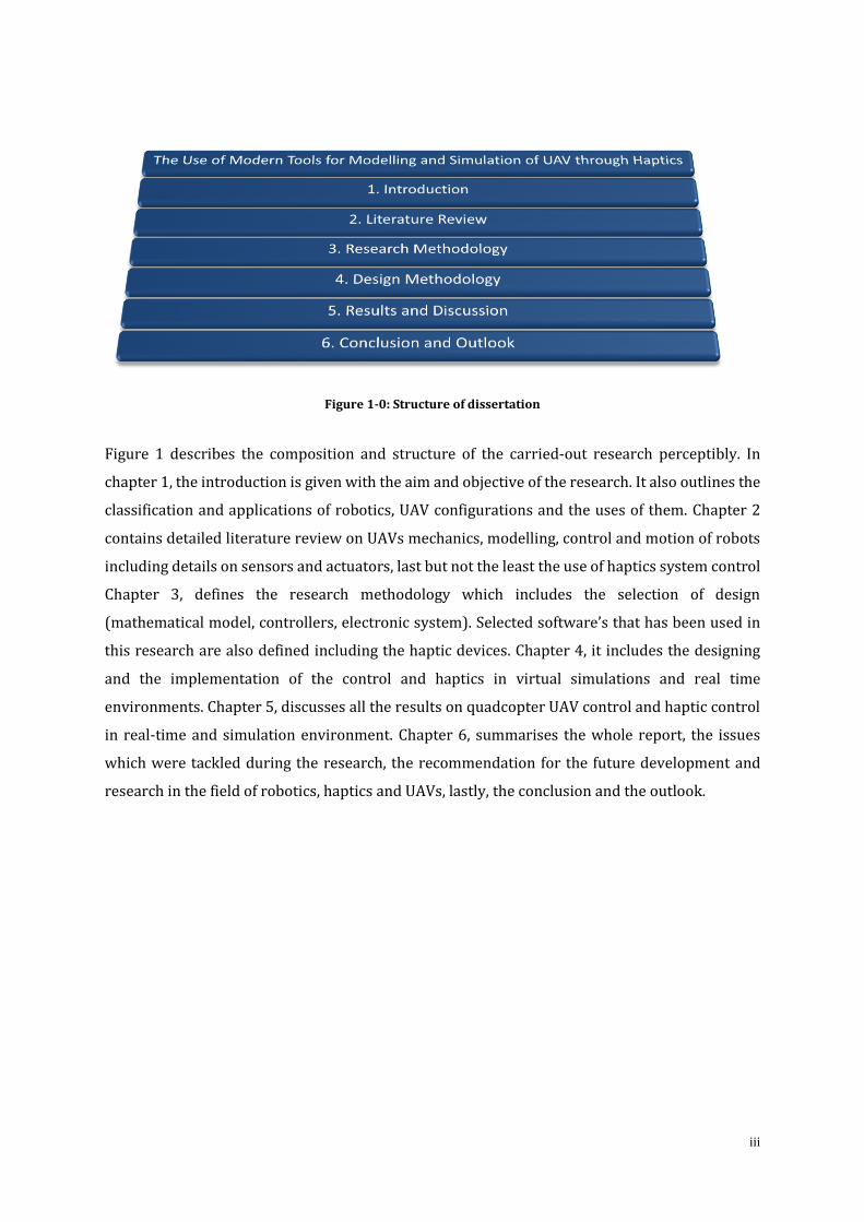
Figure 1-0: Structure of dissertation
Figure 1 describes the composition and structure of the carried-out research perceptibly. In
chapter 1, the introduction is given with the aim and objective of the research. It also outlines the
classification and applications of robotics, UAV configurations and the uses of them. Chapter 2
contains detailed literature review on UAVs mechanics, modelling, control and motion of robots
including details on sensors and actuators, last but not the least the use of haptics system control
Chapter 3, defines the research methodology which includes the selection of design
(mathematical model, controllers, electronic system). Selected software’s that has been used in
this research are also defined including the haptic devices. Chapter 4, it includes the designing
and the implementation of the control and haptics in virtual simulations and real time
environments. Chapter 5, discusses all the results on quadcopter UAV control and haptic control
in real-time and simulation environment. Chapter 6, summarises the whole report, the issues
which were tackled during the research, the recommendation for the future development and
research in the field of robotics, haptics and UAVs, lastly, the conclusion and the outlook.
iv
Acknowledgements
I am very obliged to the following contributors to this thesis in a way or another.
I sincerely wish to thank my supervisor Dr. Nabil Aouf and for his constant guidance,
motivation, technical advice and encouragement during the course of this research
project.
To my committee members, especially Professor Mark Richardson for his advice.
To Cranfield University & Defence Academy of United Kingdom for providing an
excellent environment and facilities to conduct the research. Also, to BAE Systems for
providing the funding for the research.
To Professor Alexander Vladislav for his advice and help toward the designing of the
quadcopter UAV.
To Dr. Umair Soori and Dr. Badis Djaama for their support through difficult times in
research and otherwise. Without you this experience would have been less fulfilling.
Finally, deep gratitude to my parents who, although have been far away, but have been
with me through every step of my research. To my brother who has helped me structure
this thesis and provided support throughout. To my lovely sister for making me laugh
at difficult times. Thank you all for your moral support and colossal love.
Shukar Alhamdulillah.
v
Table of Contents ABSTRACT ......................................................................................................................................................... I
PREFACE .......................................................................................................................................................... II
ACKNOWLEDGEMENTS .................................................................................................................................. IV
TABLE OF CONTENTS ....................................................................................................................................... V
LIST OF FIGURES ........................................................................................................................................... VIII
LIST OF TABLES ............................................................................................................................................... X
LIST OF SYMBOLS ........................................................................................................................................... XI
ACRONYMS ................................................................................................................................................... XII
....................................................................................................................................................... 1
Introduction ................................................................................................................................................... 1 1.1 Preamble ......................................................................................................................................................... 1 1.2 Aim & Objectives of the Research ............................................................................................................... 2 1.3 Classification & Application of Robotics....................................................................................................... 4 1.4 UAV Configurations ......................................................................................................................................... 6 1.5 UAVs in Real Life ........................................................................................................................................... 7
1.5.1 Use of UAVs ......................................................................................................................................... 8 1.6 Organisation of Report .................................................................................................................................... 9
..................................................................................................................................................... 11
Literature Review ........................................................................................................................................ 11 2.1 Motivation of the Research ........................................................................................................................ 11 2.2 State of the Art ........................................................................................................................................... 12 2.3 Contribution of this Work ........................................................................................................................... 13
2.3.1 Dynamic Modelling of Quadcopter using Modern Tools .............................................................. 13 2.3.2 System Control of Quadcopter ........................................................................................................ 14 2.3.3 Haptics System Control .................................................................................................................... 14
2.4 Helicopters VS Other Flying Principles ......................................................................................................... 14 2.4.1 Short VTOL Configurations Comparison .......................................................................................... 15 2.4.2 VTOL Configurations for Future UAV .............................................................................................. 16
2.4.2.1 Coaxial Configuration ................................................................................................................... 16 2.4.2.2 Quadcopter Configuration ........................................................................................................... 17
2.5 What is Haptics? .......................................................................................................................................... 17 2.5.1 Prior Relevant Research on Haptic System Control ...................................................................... 18 2.5.2 Haptic Controllers ............................................................................................................................. 19 2.5.3 Applications of Haptic Controllers ................................................................................................... 20
2.6 Conclusion ..................................................................................................................................................... 22
..................................................................................................................................................... 23
Research Methodology ............................................................................................................................... 23 3.1 Quadcopter Anatomy ................................................................................................................................... 23
3.1.1 Design Selection ................................................................................................................................ 24 3.1.1.1 Frame ............................................................................................................................................ 24 3.1.1.2 Motors .......................................................................................................................................... 25 3.1.1.3 Propellers ...................................................................................................................................... 26 3.1.1.4 Electronic Speed Controller ........................................................................................................ 27 3.1.1.5 Battery .......................................................................................................................................... 27
vi
3.1.1.6 Flight Controller ........................................................................................................................... 28 3.1.1.7 Optical Components .................................................................................................................... 29
3.2 Mechanics of Quadcopter ........................................................................................................................... 29 3.2.1 Flight Orientations ............................................................................................................................ 30
3.2.1.1 Axis Representation ...................................................................................................................... 30 3.2.1.2 Attitude Changes ......................................................................................................................... 30
3.3 Mathematical Model of Quadcopter .......................................................................................................... 32 3.3.1 Kinematics .......................................................................................................................................... 32 3.3.2 Physics ................................................................................................................................................ 34
3.3.2.1 Motors .......................................................................................................................................... 34 3.3.2.2 Forces............................................................................................................................................ 35 3.3.2.3 Torques ......................................................................................................................................... 35 3.3.2.4 Equation of Motion ..................................................................................................................... 37
3.4 Selection of Hardware ................................................................................................................................. 37 3.4.1 AR Drone 2.0 Parrot ........................................................................................................................ 38 3.4.2 Haptic Devices ................................................................................................................................... 39
3.4.2.1 Novint Falcon ................................................................................................................................ 39 3.4.2.2 GeoMagic Touch .......................................................................................................................... 41
3.5 Selection of Software ................................................................................................................................... 42 3.5.1 Java Net Beans ................................................................................................................................. 42 3.5.2 Robot Operating System (ROS)........................................................................................................ 43 3.5.3 MATLAB & Simulink ........................................................................................................................... 43 3.5.4 SolidWorks ......................................................................................................................................... 44
3.6 Conclusion ..................................................................................................................................................... 45
..................................................................................................................................................... 46
Design Methodology ................................................................................................................................... 46 4.1 Design Concept ............................................................................................................................................. 46 4.2 System Designing .......................................................................................................................................... 48
4.2.1 Construction and Assumptions ........................................................................................................ 48 4.2.2 Aerodynamics Coefficients ................................................................................................................ 48 4.2.3 Forces and Moments ........................................................................................................................ 49
4.3 Control System ............................................................................................................................................. 51 4.3.1 Control using PID Technique ........................................................................................................... 52
4.3.1.1 PD Control Synthesis ................................................................................................................... 53 4.3.1.2 PID Control Synthesis .................................................................................................................. 53 4.3.1.3 PID Tuning .................................................................................................................................... 53
4.4 Haptic Control System .................................................................................................................................. 55 4.4.1 Haptic System for Real-Time Environment ...................................................................................... 55 4.4.2 Haptic System for Simulation Environment .................................................................................... 56
4.5 Integration and Testing ................................................................................................................................ 58 4.6 Conclusion ..................................................................................................................................................... 58
..................................................................................................................................................... 60
Results and Discussion ............................................................................................................................... 60 5.1 Final Model & Control of Quadcopter ....................................................................................................... 60 5.2 Results of Simulations and Experiments ..................................................................................................... 67
5.2.1 Control Results .................................................................................................................................. 67 5.2.1.1 PD Control .................................................................................................................................... 67 5.2.1.2 PID Control ................................................................................................................................... 68 5.2.1.3 PID Tuned Control ....................................................................................................................... 69
5.2.2 Haptic Results .................................................................................................................................... 70 5.2.2.1 Results of Simulation Environment ............................................................................................. 71 5.2.2.2 Results of Real Time Experiment ............................................................................................... 71
5.3 Conclusion ..................................................................................................................................................... 74
vii
..................................................................................................................................................... 75
Conclusion and Outlook .............................................................................................................................. 75 6.1 Model Recapitulation ................................................................................................................................... 75
6.1.1 Model Overview ................................................................................................................................ 75 6.1.2 Execution of Requirements .............................................................................................................. 76 6.1.3 Novelty ............................................................................................................................................... 77
6.2 Recommendations and Hints for Future Research .................................................................................... 78 6.3 Technologies in Use & Yet to Come ......................................................................................................... 79
6.3.1 Current Technology ........................................................................................................................... 79 6.3.2 Future Technology ............................................................................................................................ 80
6.4 Conclusion ..................................................................................................................................................... 81
BIBLIOGRAPHY ............................................................................................................................................... 86
APPENDIX I .................................................................................................................................................... 93
Components of Quadcopter Designed in SolidWorks .................................................................................. 93
APPENDIX II ................................................................................................................................................. 105
Quadcopter UAV Simulink Models Subsystems ......................................................................................... 105
APPENDIX III ................................................................................................................................................ 111
Method for integration of CAD SolidWorks Model with MATLAB/Simulink .............................................. 111
GLOSSARY .................................................................................................................................................... 113
viii
List of Figures FIGURE 1-1: CONTROLLER MECHANISM (ANON 2014) ...................................................................................................... 2
FIGURE 1-2: (LEFT TO RIGHT) SPACE ROVER, HOUSEHOLD ROBOT, AGV ROBOT, MILITARY ROBOT, EDUCATIONAL ROBOT, SWARM
ROBOT ............................................................................................................................................................. 4
FIGURE 1-3: (LEFT TO RIGHT), FACTORY ROBOT, SOFT ROBOT, HUMANOID ROBOT(ROBOTICS 2011; ZAUNER ET AL. 2012; BYKO
2008) ............................................................................................................................................................. 5
FIGURE 1-4: GENERAL CLASSIFICATION OF AIRCRAFTS (ANON 2005) .................................................................................... 7
FIGURE 2-1: COAX HELICOPTER (ANON 2012B) ............................................................................................................. 16
FIGURE 2-2: QUADCOPTER CONCEPT MOTION, THE ARROW WIDTH IS PROPORTIONAL TO PROPELLER ROTATIONAL SPEED (ANON
2013B) ......................................................................................................................................................... 17
FIGURE 3-1: TYPE OF FRAME. (LEFT TO RIGHT). ALUMINIUM, CARBON FIBRE, PLYWOOD. (MULTIPILOT 2011) ........................... 25
FIGURE 3-2: MOTOR TO MOTOR DISTANCE ON FRAME (SCARLIANG 2012) .......................................................................... 25
FIGURE 3-3: PMDC MOTOR WITH SCHEMATIC DIAGRAM (ANON 2013A; KIRAN 2016) ....................................................... 26
FIGURE 3-4: PROPELLERS OF QUADCOPTER (ANON 2015) ................................................................................................ 26
FIGURE 3-5: ELECTRONIC SPEED CONTROLLER (ANON 2015) ............................................................................................ 27
FIGURE 3-6: FLIGHT CONTROLLER (ANON 2015) ............................................................................................................ 28
FIGURE 3-7: AXIS REPRESENTATION(KHAN 2014) ........................................................................................................... 30
FIGURE 3-8: PLUS (+) FLIGHT ORIENTATION (LEFT) & X FLIGHT ORIENTATION (RIGHT) (DIGG 2014) ......................................... 31
FIGURE 3-9: INERTIAL FRAME (LEFT) & BODY FRAME OF QUADCOPTER (RIGHT) (JURAJ 2013) ................................................. 32
FIGURE 3-10: CONTRACTION OF EULER ANGLES (ANON 2012A) ........................................................................................ 33
FIGURE 3-11: AR DRONE PARROT 2.0 QUADCOPTER (GADGET 2010) ............................................................................... 38
FIGURE 3-12: NOVINT FALCONE HAPTIC CONTROLLER (FALCON 2014) ............................................................................... 40
FIGURE 3-13: GEOMAGIC TOUCH HAPTIC CONTROLLER (GEOMAGIC 2013) ........................................................................ 41
FIGURE 4-1: QUADCOPTER SCHEMATIC WITH DESCRIPTION OF ITS COMPONENTS (PHAN-DANG 2013) ...................................... 47
FIGURE 4-2: SYSTEMATIC APPROACH USED IN THIS RESEARCH ............................................................................................. 47
FIGURE 4-3: CAD MODEL OF QUADCOPTER BUILT IN SOLIDWORKS FOR VIRTUAL SIMULATION ENVIRONMENT ............................. 47
FIGURE 4-4: TOP VIEW OF QUADCOPTER WITH MOTOR CONFIGURATION (ROSENSTEIN 2013) ................................................. 48
FIGURE 4-5: CONNECTION OF TRANSLATION AND ROTATION SYSTEM .................................................................................. 52
FIGURE 4-6: NOVINT FALCON HAPTIC CONTROLLER WITH MULTIPLE LINK (1-4) TO MOTORS FOR FORCE FEEDBACK (FALCON 2014) 55
FIGURE 4-7: HIGH LEVEL OVERVIEW OF THE SYSTEM BUILT FOR REAL-TIME ENVIRONMENT EXPERIMENTS .................................... 56
FIGURE 4-8: UAV-HAPTIC TELEOPERATION PROCESS MODEL ............................................................................................ 57
FIGURE 4-9: HIGH LEVEL OVERVIEW OF THE SYSTEM BUILT FOR VIRTUAL SIMULATION ENVIRONMENT ........................................ 57
FIGURE 5-1: PD CONTROL MODEL FOR QUADCOPTER ...................................................................................................... 61
FIGURE 5-2: RESULTS OF PITCH, ROLL & YAW FROM PD CONTROL MODEL FOR QUADCOPTER ................................................ 62
FIGURE 5-3: FULL PD CONTROL MODEL FOR QUADCOPTER .............................................................................................. 62
FIGURE 5-4: INERTIAL POSITION X, Y AND Z .................................................................................................................... 64
FIGURE 5-5: CONTROL INPUT 𝝎𝒊 ................................................................................................................................. 65
FIGURE 5-6: ANGLES 𝝓. 𝜽,𝝍 ..................................................................................................................................... 65
FIGURE 5-7: FULL PID CONTROL MODEL WITH HAPTIC SYSTEM CONTROL FOR QUADCOPTER .................................................. 66
FIGURE 5-8: ANGULAR VELOCITIES (LEFT). ANGULAR DISPLACEMENTS (RIGHT). PHI, THETA, PSI ARE CODED AS BLUE, RED AND GREEN
RESPECTIVELY .................................................................................................................................................. 68
FIGURE 5-9: WITH A PROPERLY IMPLEMENTED PID, WE ACHIEVE AN ERROR OF APPROX. 0.06 DEGREES AFTER 10 SECS. PHI, THETA,
PSI ARE CODED AS BLUE, RED AND GREEN RESPECTIVELY ........................................................................................... 69
FIGURE 5-10: ANGULAR VELOCITY AND ANGULAR DISPLACEMENT MANUALLY TUNED. PHI, THETA, PSI ARE CODED AS BLUE, RED AND
GREEN RESPECTIVELY ......................................................................................................................................... 69
FIGURE 5-11: ANGULAR VELOCITY AND ANGULAR DISPLACEMENT AUTOMATIC TUNED. PHI, THETA, PSI ARE CODED AS BLUE, RED AND
GREEN RESPECTIVELY ......................................................................................................................................... 70
ix
FIGURE 5-12: SIMULATION RESULT AT INITIAL POINT, 0.23 SECS, 0.39 SEC AND 0.85 SECONDS (FROM TOP LEFT TO BOTTOM RIGHT)
.................................................................................................................................................................... 71
FIGURE 5-13: A VIEW OF JAVA BASED APPLICATION FOR QUADCOPTER CONTROLS ................................................................ 72
FIGURE 5-14: SOME VIEWS CAPTURED FORM A HOVERING QUADCOPTER ............................................................................. 72
FIGURE 5-15: APPLICATION WINDOW (LEFT), NOVINT FALCON HAPTIC DEVICE (RIGHT) ........................................................... 73
x
List of Tables TABLE 1-1: COMMON UAV CONFIGURATION ................................................................................................................... 7
TABLE 1-2: APPLICATIONS OF UAVS ............................................................................................................................... 9
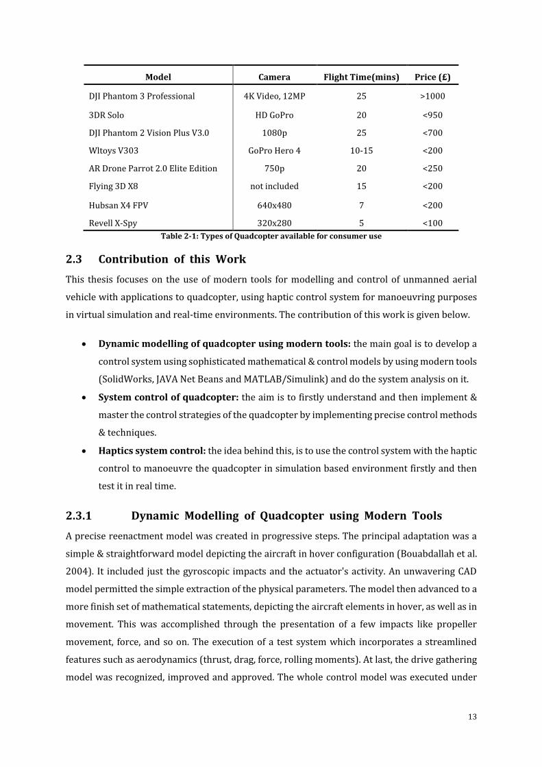
TABLE 2-1: TYPES OF QUADCOPTER AVAILABLE FOR CONSUMER USE ................................................................................... 13
TABLE 2-2: FLYING PRINCIPLES COMPARISON (1=BAD, 3=GOOD) (SIEGWART & NOURBAKHSH 2004) ..................................... 15
TABLE 2-3: VTOL CONCEPTS COMPARISON (1=BAD, 4=VERY GOOD). A=SINGLE ROTOR, B=AXIAL ROTOR, C=COAXIAL ROTORS,
D=TANDEM ROTORS, E=QUADCOPTERS, F=BLIMP, G=BIRD-LIKE, H=INSECT-LIKE (BECKER & SIEGWART 2006) ............... 15
TABLE 2-4: VARIOUS TYPE OF HAPTIC DEVICES ................................................................................................................ 20
TABLE 3-1: X & PLUS (+) FLIGHT CONFIGURATIONS (DIGG 2014) ...................................................................................... 31
TABLE 3-2: X & PLUS (+) MOTOR OUT CONFIGURATIONS (T=THROTTLE, P=PITCH, R=ROLL, Y=YAW) (DIGG 2014) ................... 32
TABLE 4-1: SUMMARY OF THE FEEDBACK CONDITIONS ..................................................................................................... 56
TABLE 5-1: PARAMETER VALUES FOR SIMULATION ........................................................................................................... 63
xi
List of Symbols
a Lift Slope A is the area swept out buy the propeller
b Dimensioned Constant
CD Dimensionless Constant
F Vector having components Fx, Fy, Fz,
F External forces acting on the aircraft
FD Drag force of body frame
g Acceleration due to gravity
H Angular momentum of the quadcopter relative to the ground inertial frame
Ixx,yy,zz Inertia Moments
IM Moment of inertia about the motor z-axis i Input Current
Io Current when there is no load on the motor
Ki/Cd Drag Coefficient
Kt Torque Proportionality Constant
Kv Proportionality Constant
L The distance between any given propeller and the centre of the quadcopter
M Moment the quadcopter experienced
R Rotation Matrix
Rm Motor Resistance
Rrad Propeller radius
T Thrust Magnitude
TB Thrust Vector Body Frame
U Control Inputs
V Speed of Quadcopter
Vh Air velocity when quadcopter is hovering
x, y, z position in body coordinate frame
𝜃o Pitch of incidence
tw Twist pitch
τ Motor-time Constant
τa Torque in body coordinate system
τd Motor Load
τm Motor Torque
𝜇 Rotor Advance Ratio
ωm Motor Angular Rate
Ω Propeller angular rate
Ωr Overall residual propeller angular speed
ώ Angular Acceleration of the Propeller
∇ Gradient
Solidity Ratio
Inflow ratio
Induced Velocity
xii
Acronyms
API Application Program Interface
ASL Autonomous Systems Laboratory
BLDC Brush-Less Direct Current
CAD Computer Aided Design
CAE Computer Aided Engineering
CPU Central Processing Unit
DARPA Defence Advance Research Project Agency
DC Direct Current
ESC Electronic Speed Controller
GPS Global Positioning System
GUI Graphical User Interface
HTA Heavier Than Air
IGE In Ground Effect
IMU Inertial Measurement Unit
LTA Lighter Than Air
MAV Micro Aerial Vehicle
MEMS Micro Electro-Mechanical Systems
MFR Miniature Flying Robots
PC Personal Computer
PCB Printed Circuit Board
PD Proportional Derivative
PG Propulsion Group
PID Proportional Integral Derivative
PMDC Permanent Magnet Direct Current Motor
PPM Pulse Position Modulation
PUMA Programmable Universal Manipulation Arm
NASA National Aeronautics and Space Administration
ROS Robot Operating System
RPM Rotations per Minute
SDK System Development Kit
STEM Science, Technology, Engineering and Math
SUAV Small Unmanned Aerial Vehicle
UAV Unmanned Aerial Vehicle
UAS Unmanned Aerial System
UGV Unmanned Ground Vehicle
VTOL Vertical Take-off and Landing

1
(Intentionally left blank)

1
“Perseverance is a great element of success.
If you only knock long enough and loud enough at the gate,
you are sure to wake up somebody.”
~ Henry Wadsworth Longfellow
1
(Intentionally left blank)
1
Introduction
“The best way to have an idea is to have lots of ideas .”
[Linus Pauling]
The undertaken research is surrounded by the fields of robotics and aerospace. Mechanical and
electrical sciences play an interdisciplinary role in the research fields including various
disciplines such as artificial intelligence and computer science (Akhtar 2013). This helps in
understanding the concepts behind the unmanned aerial vehicles, robotics programming, haptic
control and designing using modern tools. It also helps in understanding how the brain of the
robot functions and process information and how the machine utilizes it using software
technologies and new computing system architectures (Akhtar 2013).
The real endeavour of this thesis is to use modern tools to model & simulate quadcopter with
haptic control system in a virtual simulation and real time environments based on the principal
findings of robotics, aerospace and artificial intelligence which will lead us to better
understanding of unmanned aerial vehicle and their applications in real life. In this chapter, the
aim of the thesis is outlined in detail, classification and applications of robotics, the use of UAVs
and lastly the organisation of this report is given.
1.1 Preamble
The author has previously mentioned in (Akhtar 2013), in the modern world, the field robotics
has become very popular and useful. It has succeeded in various fields and applications which are
being used by humans. “Robotics is the science and technology behind the design, manufacturing
and application of robots. Robotics develop man-made mechanical devices that can move by
themselves, whose motion must be modelled, planned, sensed, actuated and controlled, and
whose motion behaviour can be influenced by programming. This definition implies that a device
2
can only be called a robot if it contains a movable mechanism, influenced by sensing, planning,
and actuation and control components.” (Akhtar 2013). It does not imply that a minimum number
of these components must be implemented in software, or be changeable by the consumer who
uses the device. (Akhtar 2013)
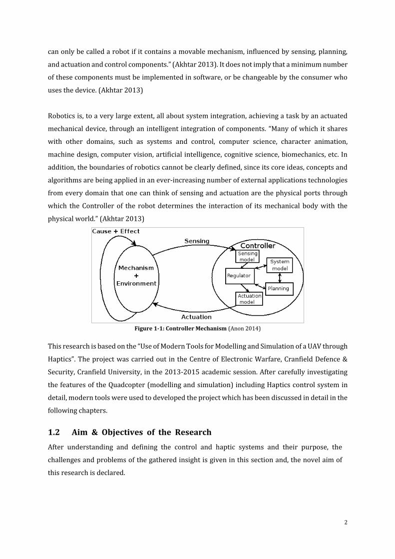
Robotics is, to a very large extent, all about system integration, achieving a task by an actuated
mechanical device, through an intelligent integration of components. “Many of which it shares
with other domains, such as systems and control, computer science, character animation,
machine design, computer vision, artificial intelligence, cognitive science, biomechanics, etc. In
addition, the boundaries of robotics cannot be clearly defined, since its core ideas, concepts and
algorithms are being applied in an ever-increasing number of external applications technologies
from every domain that one can think of sensing and actuation are the physical ports through
which the Controller of the robot determines the interaction of its mechanical body with the
physical world.” (Akhtar 2013)
Figure 1-1: Controller Mechanism (Anon 2014)
This research is based on the “Use of Modern Tools for Modelling and Simulation of a UAV through
Haptics”. The project was carried out in the Centre of Electronic Warfare, Cranfield Defence &
Security, Cranfield University, in the 2013-2015 academic session. After carefully investigating
the features of the Quadcopter (modelling and simulation) including Haptics control system in
detail, modern tools were used to developed the project which has been discussed in detail in the
following chapters.
1.2 Aim & Objectives of the Research
After understanding and defining the control and haptic systems and their purpose, the
challenges and problems of the gathered insight is given in this section and, the novel aim of
this research is declared.
3
The main purpose of this thesis is to use modern tools for modelling and simulation of
quadcopter UAV using haptic control system for realizing the concept and use of UAVs in the
near future. This model will help understand the movement and behaviour of the quadcopter
in real time by using haptic controls in virtual simulations and real life environments.
The two main aspects of this project are the modelling and simulation of the quadcopter using
modern tools and how the controls are used with haptic for controlling the quadcopter in real
life experiments. The first step was to find an optimal model for the quadcopter which can be
easily designed and developed using cheap resources. The major issue in modelling the
quadcopter is the types of control it requires for different scenarios. Therefore, after
researching the conclusion was; that most the time quadcopter is going to be used in a
closed/indoor environment and hence the work carried should suit this purpose. The second
step was to design a controller with basic features in a simulation environment and then
evolved it further with precise coefficients as necessary to obtain accurate results. After
completion of this phase, the next part was to use the controls with a haptic device to control
the quadcopter. For this, investigation was done on haptic devices and found many available
with advanced controls. As per the requirements of the research and expense two devices were
selected i.e. Novint Falcon and GeoMagic Touch. And they turned out very well in the end.
At the first instance when the research project was outlined; having no prior knowledge about
haptics control systems or devices for these type of applications, it was amazing to see how big
are the possibilities and applications for a small haptic device which I have only used for gaming
purpose. Furthermore, the control system for quadcopter was something new, therefore it was
necessary to understand the concepts behind the control system and haptics. The major
problem faced was studying about haptics as it requires programming to make it work and not
having used Linux prior to this research made it quite troublesome in the starting.
The work started by learning and designing basic controls that can be used for quadcopter and
implemented some of them to see how they work. After implementing some of the control system
it was decided that PID and PD controllers would be suitable for this research. On the other hand,
haptics was the most important and novel part of project therefore getting to understand the
concepts behind it was fundamental. To use the functions of the haptic device, one needs to
understand the API and SDK so implementation can be done at the later stage for haptic system
control. The detailed model of the quadcopter with haptic control is described later in this report.
4
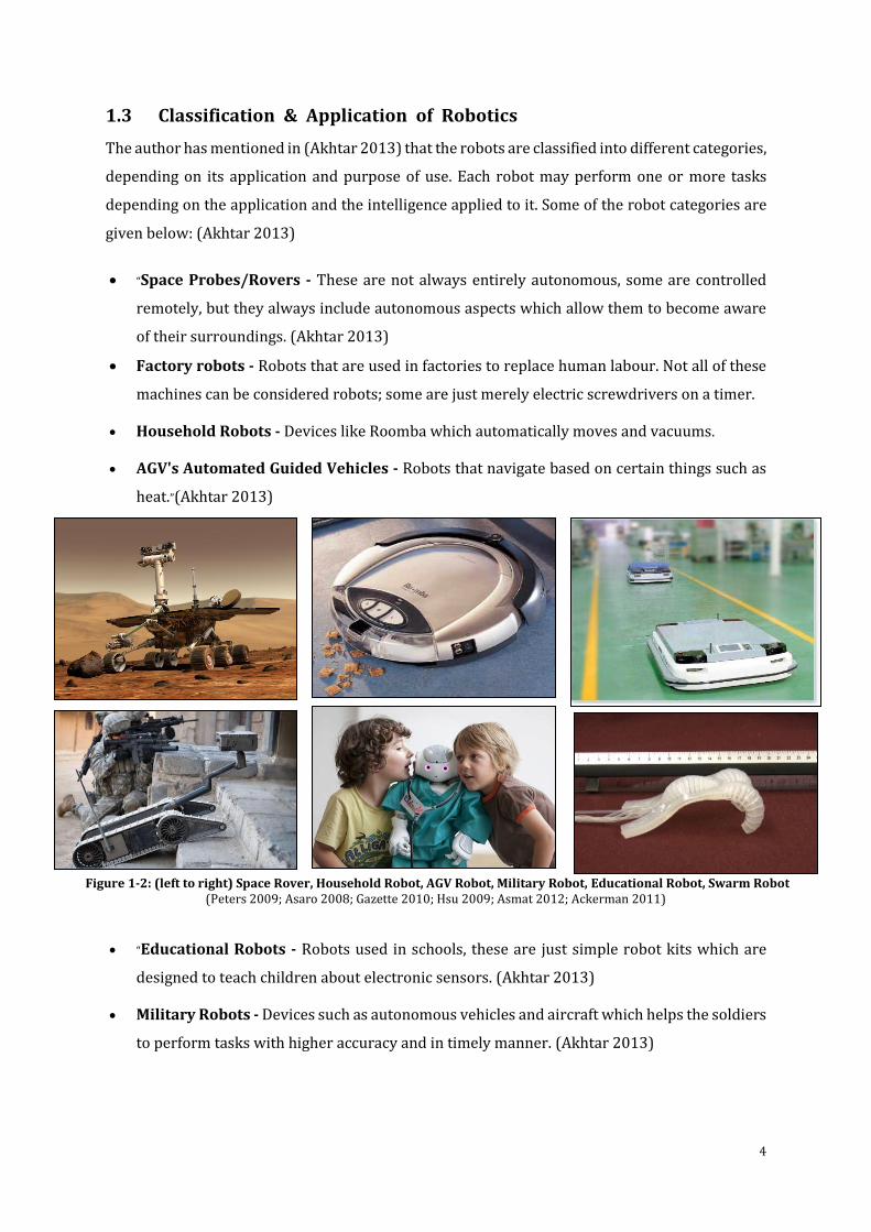
1.3 Classification & Application of Robotics
The author has mentioned in (Akhtar 2013) that the robots are classified into different categories,
depending on its application and purpose of use. Each robot may perform one or more tasks
depending on the application and the intelligence applied to it. Some of the robot categories are
given below: (Akhtar 2013)
“Space Probes/Rovers - These are not always entirely autonomous, some are controlled
remotely, but they always include autonomous aspects which allow them to become aware
of their surroundings. (Akhtar 2013)
Factory robots - Robots that are used in factories to replace human labour. Not all of these
machines can be considered robots; some are just merely electric screwdrivers on a timer.
Household Robots - Devices like Roomba which automatically moves and vacuums.
AGV's Automated Guided Vehicles - Robots that navigate based on certain things such as
heat.”(Akhtar 2013)
(Peters 2009; Asaro 2008; Gazette 2010; Hsu 2009; Asmat 2012; Ackerman 2011)
“Educational Robots - Robots used in schools, these are just simple robot kits which are
designed to teach children about electronic sensors. (Akhtar 2013)
Military Robots - Devices such as autonomous vehicles and aircraft which helps the soldiers
to perform tasks with higher accuracy and in timely manner. (Akhtar 2013)
Figure 1-2: (left to right) Space Rover, Household Robot, AGV Robot, Military Robot, Educational Robot, Swarm Robot
5
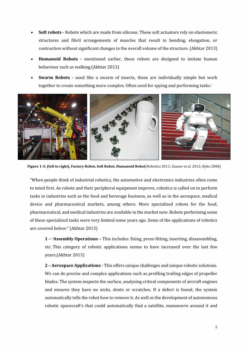
Soft robots - Robots which are made from silicone. These soft actuators rely on elastomeric
structures and fibril arrangements of muscles that result in bending, elongation, or
contraction without significant changes in the overall volume of the structure. (Akhtar 2013)
Humanoid Robots - mentioned earlier, these robots are designed to imitate human
behaviour such as walking.(Akhtar 2013)
Swarm Robots - used like a swarm of insects, these are individually simple but work
together to create something more complex. Often used for spying and performing tasks.”
“When people think of industrial robotics, the automotive and electronics industries often come
to mind first. As robots and their peripheral equipment improve, robotics is called on to perform
tasks in industries such as the food and beverage business, as well as in the aerospace, medical
device and pharmaceutical markets, among others. More specialized robots for the food,
pharmaceutical, and medical industries are available in the market now. Robots performing some
of these specialised tasks were very limited some years ago. Some of the applications of robotics
are covered below:” (Akhtar 2013)
1 – “Assembly Operations – This includes: fixing, press-fitting, inserting, disassembling,
etc. This category of robotic applications seems to have increased over the last few
years.(Akhtar 2013)
2 – Aerospace Applications - This offers unique challenges and unique robotic solutions.
We can do precise and complex applications such as profiling trailing edges of propeller
blades. The system inspects the surface, analysing critical components of aircraft engines
and ensures they have no nicks, dents or scratches. If a defect is found, the system
automatically tells the robot how to remove it. As well as the development of autonomous
robotic spacecraft’s that could automatically find a satellite, manoeuvre around it and
Figure 1-3: (left to right), Factory Robot, Soft Robot, Humanoid Robot(Robotics 2011; Zauner et al. 2012; Byko 2008)
6
eventually realize maintenance missions are the interest of different space agencies.
(Akhtar 2013)
3 – Assistive Robots - During the last years the rehabilitation technology is developing
towards more flexible and adaptable robotic systems. These robots aim at supporting
disable and elderly people with special needs in their home environment. (Akhtar 2013)
4 – Mobile Manipulators - The main objective of Manfred Mobile Manipulator is the
development of new capabilities to operate into the environment. The development of a
new sensor-based planning and control architecture will allow the integration of sensor
information coming from a laser scan, vision and a force/torque sensor. (Akhtar 2013)
5 – Applications of Hazardous Situation - Robotic systems are currently being
developed for hazardous applications such as for the building and repair of skyscrapers
and large buildings. Such systems can potentially be adapted to perform tasks such as
window-cleaning and glass repair. Other hazardous situations to which robots have been
applied include the bridge inspections, ship hull inspections, painting of large building,
maintenance and repair of nuclear power stations.” (Akhtar 2013)
Robotics also simulate repair of orbiting satellites. “The National Aeronautics and Space
Administration’s (NASA) satellite servicing initiative wants the ability to change batteries, refuel or
repair satellites. Otherwise, a satellite becomes space junk and is a lost investment.” (Brumson
2011)
“Robots have also been used to explore hostile environments such as warzones/minefields for
surveillance and hazard detection. These include the use of UAV (unmanned air vehicles) which
are used to relay images of potential risks and target areas to the controller. Bomb disposal units
are also used for similar reasons through which the risk of human injury is reduced.” (Akhtar
2013)
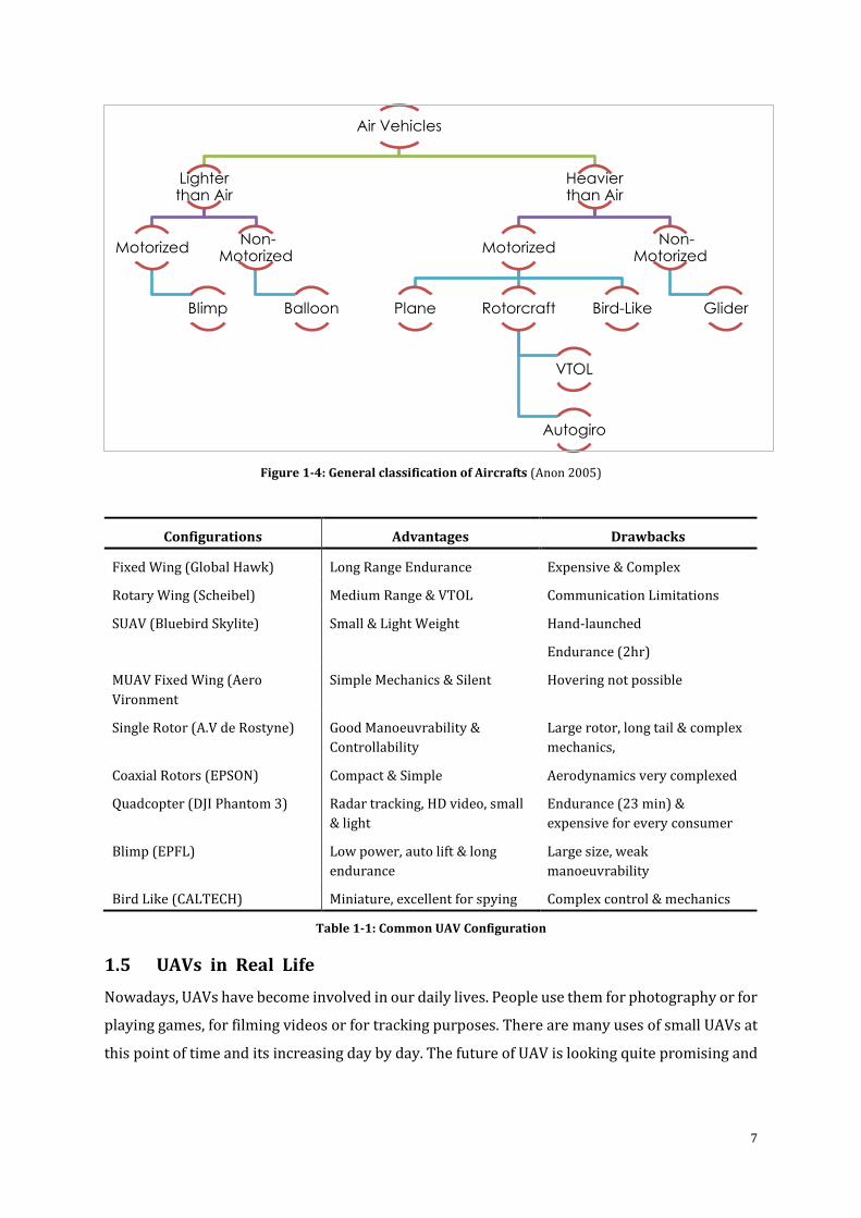
1.4 UAV Configurations
Overall, the aerial vehicle can be classified into two classes, which are Heavier than Air (HTA) and
Lighter than Air (LTA). In Figure1-4 the organization of aircraft reliant on the propulsion mode
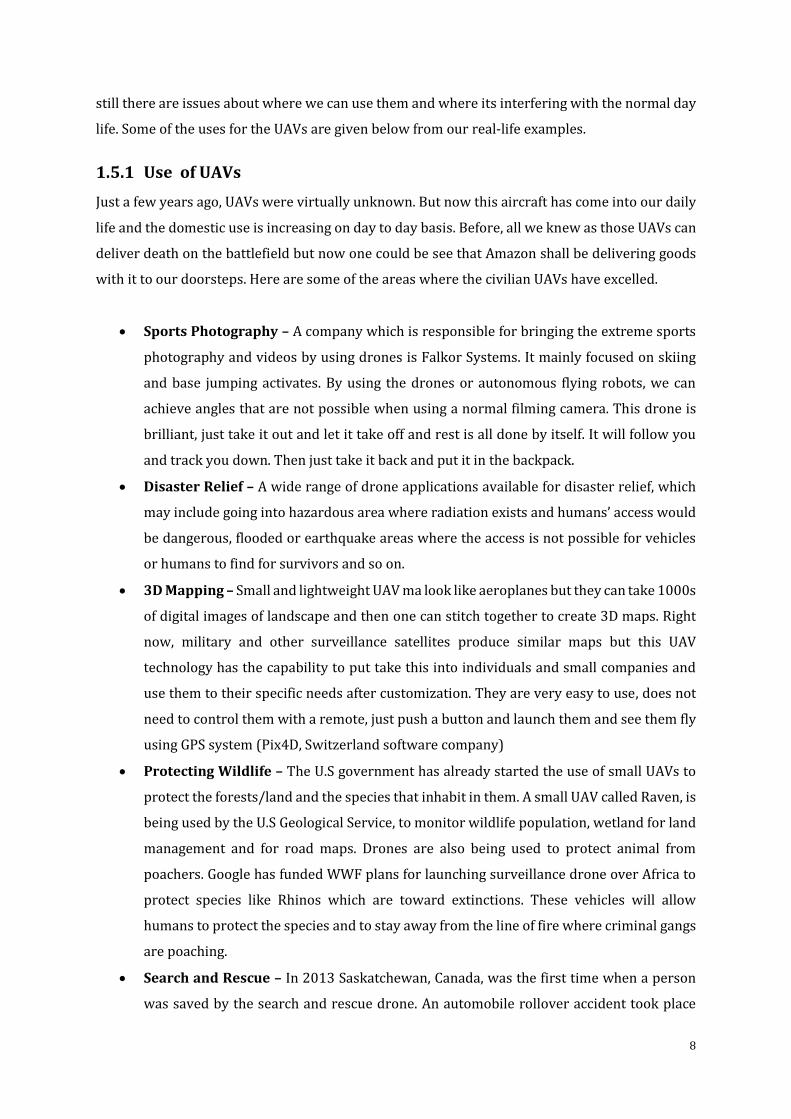
and flying principles are shown. Table 1-1 classifies the different types of commonly used UAV in
research and industry.
7
Figure 1-4: General classification of Aircrafts (Anon 2005)
Configurations Advantages Drawbacks
Fixed Wing (Global Hawk) Long Range Endurance Expensive & Complex
Rotary Wing (Scheibel) Medium Range & VTOL Communication Limitations
SUAV (Bluebird Skylite) Small & Light Weight Hand-launched
Endurance (2hr)
MUAV Fixed Wing (Aero
Vironment
Simple Mechanics & Silent Hovering not possible
Single Rotor (A.V de Rostyne) Good Manoeuvrability &
Controllability
Large rotor, long tail & complex
mechanics,
Coaxial Rotors (EPSON) Compact & Simple Aerodynamics very complexed
Quadcopter (DJI Phantom 3) Radar tracking, HD video, small
& light
Endurance (23 min) &
expensive for every consumer
Blimp (EPFL) Low power, auto lift & long
endurance
Large size, weak
manoeuvrability
Bird Like (CALTECH) Miniature, excellent for spying Complex control & mechanics
Table 1-1: Common UAV Configuration
1.5 UAVs in Real Life
Nowadays, UAVs have become involved in our daily lives. People use them for photography or for
playing games, for filming videos or for tracking purposes. There are many uses of small UAVs at
this point of time and its increasing day by day. The future of UAV is looking quite promising and
Air Vehicles
Lighter than Air
Motorized
Blimp
Non-Motorized
Balloon
Heavier than Air
Motorized
Plane Rotorcraft
VTOL
Autogiro
Bird-Like
Non-Motorized
Glider
8
still there are issues about where we can use them and where its interfering with the normal day
life. Some of the uses for the UAVs are given below from our real-life examples.
1.5.1 Use of UAVs
Just a few years ago, UAVs were virtually unknown. But now this aircraft has come into our daily
life and the domestic use is increasing on day to day basis. Before, all we knew as those UAVs can
deliver death on the battlefield but now one could be see that Amazon shall be delivering goods
with it to our doorsteps. Here are some of the areas where the civilian UAVs have excelled.
Sports Photography – A company which is responsible for bringing the extreme sports
photography and videos by using drones is Falkor Systems. It mainly focused on skiing
and base jumping activates. By using the drones or autonomous flying robots, we can
achieve angles that are not possible when using a normal filming camera. This drone is
brilliant, just take it out and let it take off and rest is all done by itself. It will follow you
and track you down. Then just take it back and put it in the backpack.
Disaster Relief – A wide range of drone applications available for disaster relief, which
may include going into hazardous area where radiation exists and humans’ access would
be dangerous, flooded or earthquake areas where the access is not possible for vehicles
or humans to find for survivors and so on.
3D Mapping – Small and lightweight UAV ma look like aeroplanes but they can take 1000s
of digital images of landscape and then one can stitch together to create 3D maps. Right
now, military and other surveillance satellites produce similar maps but this UAV
technology has the capability to put take this into individuals and small companies and
use them to their specific needs after customization. They are very easy to use, does not
need to control them with a remote, just push a button and launch them and see them fly
using GPS system (Pix4D, Switzerland software company)
Protecting Wildlife – The U.S government has already started the use of small UAVs to
protect the forests/land and the species that inhabit in them. A small UAV called Raven, is
being used by the U.S Geological Service, to monitor wildlife population, wetland for land
management and for road maps. Drones are also being used to protect animal from
poachers. Google has funded WWF plans for launching surveillance drone over Africa to
protect species like Rhinos which are toward extinctions. These vehicles will allow
humans to protect the species and to stay away from the line of fire where criminal gangs
are poaching.
Search and Rescue – In 2013 Saskatchewan, Canada, was the first time when a person
was saved by the search and rescue drone. An automobile rollover accident took place
9
late at night in a remote location and the driver was disoriented, wandered off. Air
ambulance with night vision and ground search was unable to find him. But then a mobile
call from the injured victim gave them an idea of his whereabouts and a Dragon Flyer X4-
ES with hat sensing capability was launched and later they found the victim before he
could potentially die due to subfreezing temperatures. This was the first known search
and rescue mission done by a UAV. Using well-equipped drone, soon it will become a
standard way to cover a large area which is inaccessible in day/night.
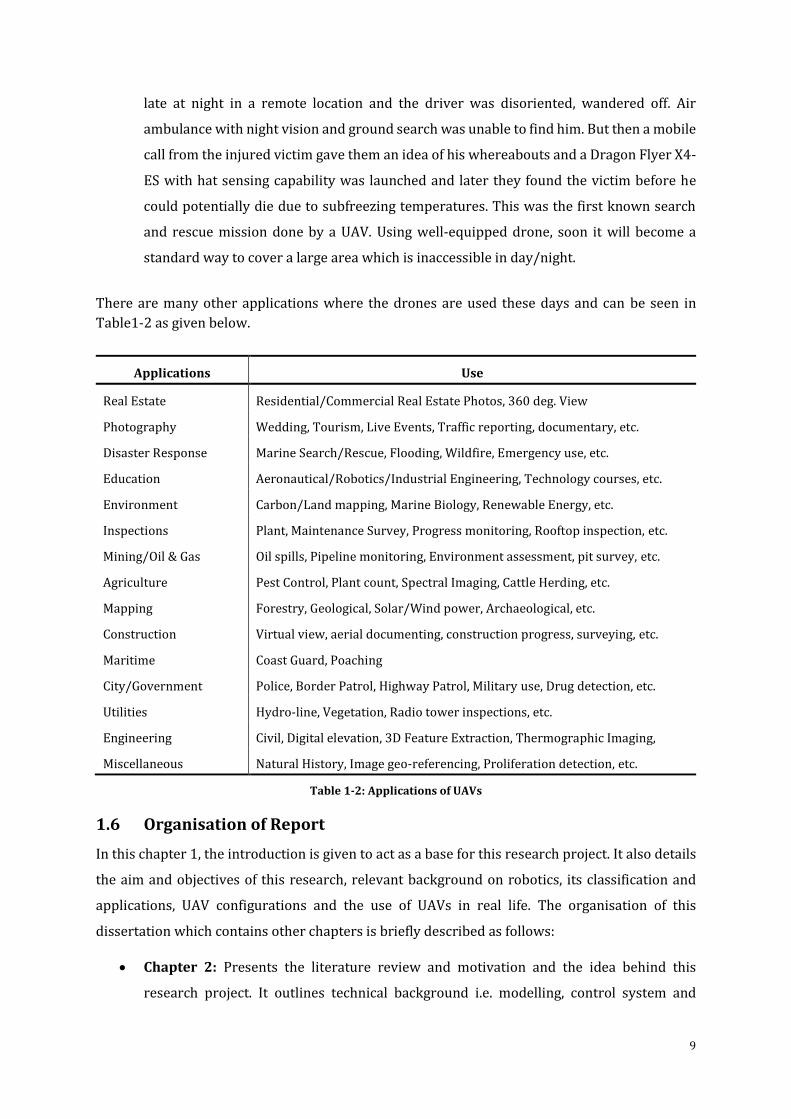
There are many other applications where the drones are used these days and can be seen in
Table1-2 as given below.
Applications Use
Real Estate Residential/Commercial Real Estate Photos, 360 deg. View
Photography Wedding, Tourism, Live Events, Traffic reporting, documentary, etc.
Disaster Response Marine Search/Rescue, Flooding, Wildfire, Emergency use, etc.
Education Aeronautical/Robotics/Industrial Engineering, Technology courses, etc.
Environment Carbon/Land mapping, Marine Biology, Renewable Energy, etc.
Inspections Plant, Maintenance Survey, Progress monitoring, Rooftop inspection, etc.
Mining/Oil & Gas Oil spills, Pipeline monitoring, Environment assessment, pit survey, etc.
Agriculture Pest Control, Plant count, Spectral Imaging, Cattle Herding, etc.
Mapping Forestry, Geological, Solar/Wind power, Archaeological, etc.
Construction Virtual view, aerial documenting, construction progress, surveying, etc.
Maritime Coast Guard, Poaching
City/Government Police, Border Patrol, Highway Patrol, Military use, Drug detection, etc.
Utilities Hydro-line, Vegetation, Radio tower inspections, etc.
Engineering Civil, Digital elevation, 3D Feature Extraction, Thermographic Imaging,
Miscellaneous Natural History, Image geo-referencing, Proliferation detection, etc.
Table 1-2: Applications of UAVs
1.6 Organisation of Report
In this chapter 1, the introduction is given to act as a base for this research project. It also details
the aim and objectives of this research, relevant background on robotics, its classification and
applications, UAV configurations and the use of UAVs in real life. The organisation of this
dissertation which contains other chapters is briefly described as follows:
Chapter 2: Presents the literature review and motivation and the idea behind this
research project. It outlines technical background i.e. modelling, control system and
10
haptic control of quadcopter using modern tools. It also states the VTOL configurations
and haptic controllers and prior research haptic system control.
Chapter 3: Presents the research methodology that is used in this research. It presents
preparation of research models such as quadcopter components, mechanics, flight
orientations, basic mathematical model which included the kinematics and physics. It also
provides detail of the software (Solid Works, Java Net Beans and MATLAB Simulink) and
hardware (AR Drone 2.0 Parrot, Novint Falcon and GeoMagic Touch) selection for this
research.
Chapter 4: Provides the design methodology for the gathered information in the previous
chapters. It presents design concept which included construction of the mathematical
system, aerodynamics, forces and moments details. It also states the control models i.e.
PID and PD controllers with manual and automatic tuning. In the end its details the
integration and testing.
Chapter 5: Explanation of all the results from the designed control models. It describes
the final control model of quadcopter UAV with haptic control system. The results of PID
and PD controller with tuning is explained and all the results of haptic system control in
virtual simulation and real-time environments.
Chapter 6: Presents the conclusions and outlook of this research work and states the
future development of this project.
11
Literature Review
“The next best thing to being clever is being able to quote someone who is.”
[Mara Pettibone Poole]
The research undertaken in this thesis is based on various research fields. In this chapter, prior
research in the field undertaken here is described, then the concepts which are fundamental for
this research are summarised so the base of this research can be laid. It states the contribution of
this research and the motivation behind it. Furthermore, UAV configurations and Haptic Devices
details are also given. It also summarises the prior on haptic control system which is the novel
and integral part of this research work. All of this contributes towards the understanding and
development of control system of quadcopter with haptic system.
2.1 Motivation of the Research
Flying items have constantly applied an incredible interest on man empowering a wide range of
innovative work. This hypothesis began in 2013, a period at which the anatomy of robotics was
demonstrating a developing enthusiasm for Unmanned Aerial Vehicle (UAV) advancement. The
technical challenges in UAV modelling and control in various tangled situations and the absence
of good arrangements was extremely persuading. Then again, the wide application in both regular
consumer markets and military were empowering the financing of UAV related development. In
the meantime, the Autonomous Systems Laboratory (ASL) had effectively aggregated a huge
ordeal on UGV with incredible results (such as, efficient control system, object avoidance system,
night vision system). These systems have made a tremendous difference when operating the
robots in difficulty situations. It gave them more flexibility, controllability and options to use
where large human or large equipment cannot go. A few proposals were led on navigation,
restriction, localization, and impediment evasion and so on. The constraints of ground-based
robots in harsh landscape and the late advancement in small scale innovation hooked us in the
direction of growing novel portability ideas. This incorporates flying frameworks on which one
12
could apply the systems effectively created on ground-based robots. On the other hand, the
undertaking is not minor because of a few open difficulties. In the field of perceiving innovations,
industry can as of now gives another era of incorporated miniaturized scale Inertial Measurement
Unit (IMU) made of Micro Electro-Mechanical Systems (MEMS) innovation magneto-resistive and
inertial sensors. The most recent innovation in this regards offers around 190 Wh/kg (which is
light weight, has more power and cheaper as compared to normal ones) which is a genuine hop
ahead particularly for smaller scale aeronautical mechanical autonomy or UAVs. This innovation
was initially produced for hand-held applications and is presently generally utilized as a part of
flying robot’s autonomy. The expense and size depletion of such frameworks makes it extremely
fascinating for the non-military personnel market. This decrease of expense and size suggests
execution and subsequently a more difficult control. In addition, the scaling down of inertial
sensors forces the utilisation of MEMS innovation, but still a great deal less exact than the routine
sensors because of drift and noise. Then again, and notwithstanding the most recent advancement
in little actuators, the scaling id still unfavourable and needs to confront the issues related to
actuator involvement. Even though the outline of small UAV robots (aerial) is conceivable, the
controls are still in early stages and a testing objective. It was chosen from the earliest starting
point of this hypothesis to take a shot at a specific VTOL arrangement: the quadcopter. The
interest is not just from dynamics point of view, which speaks to appealing controlling issue, but
also from the structural point of view and its issues. Synchronizing the actuators, sensors and
understanding a lightweight VTOL framework with a decent functional period is not paltry.
2.2 State of the Art
The state of the art in quadcopter UAV control has changed in the most recent couple of years.
The quantity of activities handling this issue has extensively and suddenly expanded. The greater
part of these ventures depends on monetarily accessible toys like the Draganflyer (DraganFly
2014), altered thereafter to have more tangible correspondence abilities. Just a few individuals
have handled the MFR plan issue, and even less did it in the ideal way (synchronous thought of
outline and control) for a quadcopter. Mesicopter development begun in 1999-2001. “It planned
to think about the possibility of a centimetre scale quadcopter. The project's driving application
was the arrangement over vast regions or planets of an immense number of smaller scale vehicles
giving climatic and meteorological information. Starmac, another intriguing venture, it focuses on
the exhibit of multi specialists control of quadcopters of around 1 kg”. Be that as it may, none of
these frameworks was based in view of a reasonable and deliberate configuration advancement
technique.
13
Model Camera Flight Time(mins) Price (£)
DJI Phantom 3 Professional 4K Video, 12MP 25 >1000
3DR Solo HD GoPro 20 <950
DJI Phantom 2 Vision Plus V3.0 1080p 25 <700
Wltoys V303 GoPro Hero 4 10-15 <200
AR Drone Parrot 2.0 Elite Edition 750p 20 <250
Flying 3D X8 not included 15 <200
Hubsan X4 FPV 640x480 7 <200
Revell X-Spy 320x280 5 <100
Table 2-1: Types of Quadcopter available for consumer use
2.3 Contribution of this Work
This thesis focuses on the use of modern tools for modelling and control of unmanned aerial
vehicle with applications to quadcopter, using haptic control system for manoeuvring purposes
in virtual simulation and real-time environments. The contribution of this work is given below.
Dynamic modelling of quadcopter using modern tools: the main goal is to develop a
control system using sophisticated mathematical & control models by using modern tools
(SolidWorks, JAVA Net Beans and MATLAB/Simulink) and do the system analysis on it.
System control of quadcopter: the aim is to firstly understand and then implement &
master the control strategies of the quadcopter by implementing precise control methods
& techniques.
Haptics system control: the idea behind this, is to use the control system with the haptic
control to manoeuvre the quadcopter in simulation based environment firstly and then
test it in real time.
2.3.1 Dynamic Modelling of Quadcopter using Modern Tools
A precise reenactment model was created in progressive steps. The principal adaptation was a
simple & straightforward model depicting the aircraft in hover configuration (Bouabdallah et al.
2004). It included just the gyroscopic impacts and the actuator's activity. An unwavering CAD
model permitted the simple extraction of the physical parameters. The model then advanced to a
more finish set of mathematical statements, depicting the aircraft elements in hover, as well as in
movement. This was accomplished through the presentation of a few impacts like propeller
movement, force, and so on. The execution of a test system which incorporates a streamlined
features such as aerodynamics (thrust, drag, force, rolling moments). At last, the drive gathering
model was recognized, improved and approved. The whole control model was executed under
14
MATLAB/Simulink and utilised to improve the configuration and to tune the control parameters.
The details of the MATLAB/simulink model is shown later on in this report
2.3.2 System Control of Quadcopter
A critical piece of this report was devoted to discovering a decent control approach for
quadcopters. A few systems were investigated from hypothetical development to theoretical
analyses. Two direct controllers, a Proportional Integral Derivative (PID) and Proportional
Derivative (PD), were examined considering a streamlined model. The primary result was an
unstable hovering flight. After further investigation and experiments which includes the precise
elements of the quadcopter control, made the model stable in hovering mode and the altitude can
be kept stable to the desired value, the control system was finalised.
2.3.3 Haptics System Control
The third step and the most integral and novel part of this project was to introduce Haptic system
control with the control system of the quadcopter. After the control was finalised for the
quadcopter, haptic device (GeoMagic Touch) was introduced with the control model of the
quadcopter for manoeuvring purposes in a virtual simulation environment. The results of this are
detailed later in the report. Furthermore, another haptic device was used (Novint Falcon) which
was used to manoeuvre the quadcopter in real-time environment. The results of the experiments
are also detailed later in the report.
2.4 Helicopters VS Other Flying Principles
As discussed above, various flying philosophies, VTOL frameworks have particular attributes
which permit the execution of uses that would be troublesome or inconceivable with different
ideas. Table 2-2 gives a comprehensive list of correlation of distinctive flying standards from the
UAV perspective. It can be seen, the undoubtedly reason, VTOL frameworks such as helicopters
or zeppelins have leverage over the different models in the UAV class. This prevalence is owed
over their one of a kind capacity for vertical, stationary and low speed flight. The key facts that
make the zeppelins take advantage is the "auto-lift" and the straightforwardness of control which
can be vital in precarious situations like space research, (Elfes et al. 2003). In any case, VTOL
vehicles in distinctive designs and structures standout amongst the most encouraging flying ideas
found as far as scaling down is concerned.
15
Aeroplane Helicopter Bird Autogiro Blimp
Power cost 1 2 2 3
Control cost 2 1 1 2 3
Payload 3 2 2 2 1
Manoeuvrability 2 3 3 2 1
Stationary Flight 1 3 2 1 3
Low Speed Fly 1 3 2 2 3
Vulnerability 2 2 3 2 2
VTOL 1 3 2 1 3
Endurance 2 1 2 1 3
Miniaturization 2 3 3 2 1
Indoor usage 1 3 2 1 2
Total 19 25 24 18 25
Table 2-2: Flying principles comparison (1=Bad, 3=Good) (Siegwart & Nourbakhsh 2004)
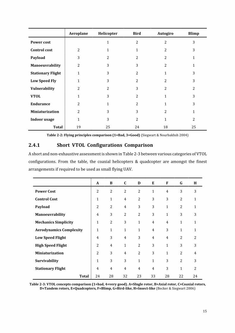
2.4.1 Short VTOL Configurations Comparison
A short and non-exhaustive assessment is shown in Table 2-3 between various categories of VTOL
configurations. From the table, the coaxial helicopters & quadcopter are amongst the finest
arrangements if required to be used as small flying UAV.
A B C D E F G H
Power Cost 2 2 2 2 1 4 3 3
Control Cost 1 1 4 2 3 3 2 1
Payload 2 2 4 3 3 1 2 1
Manoeuvrability 4 3 2 2 3 1 3 3
Mechanics Simplicity 1 2 3 1 4 4 1 1
Aerodynamics Complexity 1 1 1 1 4 3 1 1
Low Speed Flight 4 3 4 3 4 4 2 2
High Speed Flight 2 4 1 2 3 1 3 3
Miniaturization 2 3 4 2 3 1 2 4
Survivability 1 3 3 1 1 3 2 3
Stationary Flight 4 4 4 4 4 3 1 2
Total 24 28 32 23 33 28 22 24
Table 2-3: VTOL concepts comparison (1=bad, 4=very good). A=SIngle rotor, B=Axial rotor, C=Coaxial rotors, D=Tandem rotors, E=Quadcopters, F=Blimp, G=Bird-like, H=Insect-like (Becker & Siegwart 2006)
16
2.4.2 VTOL Configurations for Future UAV
From the Table 2-3 shown above categorizing different types of configurations, not all are suitable
design/structure for future VTOL UAV systems. The most promising ones are the quadcopter and
the coaxial. However, there are number of different variations of configurations developed very
recently. (Samuel et al. 2005)
2.4.2.1 Coaxial Configuration
The advancement in developing one of single rotor helicopters was historically much faster than
the development of full scale coaxial helicopters. This is predominantly because of the staggering
intricacy of their swash plate design mechanisms. Be that as it may, the upside of coaxial was
acknowledged for maritime vessels and unmanned vehicles, where space is quite restricted
(Watkinson 2003). In this design, one propeller is situated over the other on the same shaft and
the rotors turn in inverse directions, which make the requirement for a tail rotor unnecessary.
Therefore, it makes the helicopter much more compact. (Watkinson 2003)
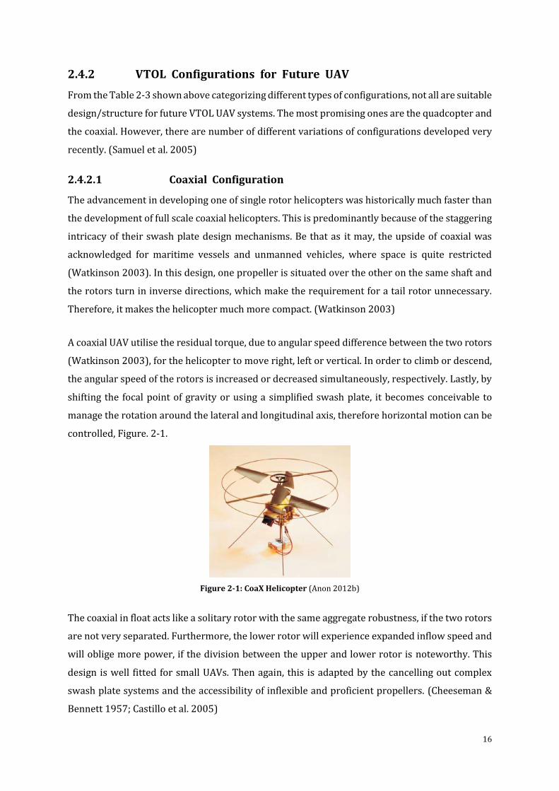
A coaxial UAV utilise the residual torque, due to angular speed difference between the two rotors
(Watkinson 2003), for the helicopter to move right, left or vertical. In order to climb or descend,
the angular speed of the rotors is increased or decreased simultaneously, respectively. Lastly, by
shifting the focal point of gravity or using a simplified swash plate, it becomes conceivable to
manage the rotation around the lateral and longitudinal axis, therefore horizontal motion can be
controlled, Figure. 2-1.
Figure 2-1: CoaX Helicopter (Anon 2012b)
The coaxial in float acts like a solitary rotor with the same aggregate robustness, if the two rotors
are not very separated. Furthermore, the lower rotor will experience expanded inflow speed and
will oblige more power, if the division between the upper and lower rotor is noteworthy. This
design is well fitted for small UAVs. Then again, this is adapted by the cancelling out complex
swash plate systems and the accessibility of inflexible and proficient propellers. (Cheeseman &
Bennett 1957; Castillo et al. 2005)
17
2.4.2.2 Quadcopter Configuration
The advancement in developing full scale quadcopter has experienced partial importance in
previous ages. Nonetheless, in 1907, the first ever manned short flight was on a quadcopter.
Today, the expansion is just limited to the category of UAV/MAV. At present, the quadcopter has
four fixed propellers in cross formation. The necessity of tail rotor has been cancelled out by
controlling the two pairs of propellers in opposite directions. Accordingly, the vertical rotation
can be achieved by having a speed difference between the two pairs of the propellers. Climbing
and descending can be done by increasing or decreasing the speed of all the propellers
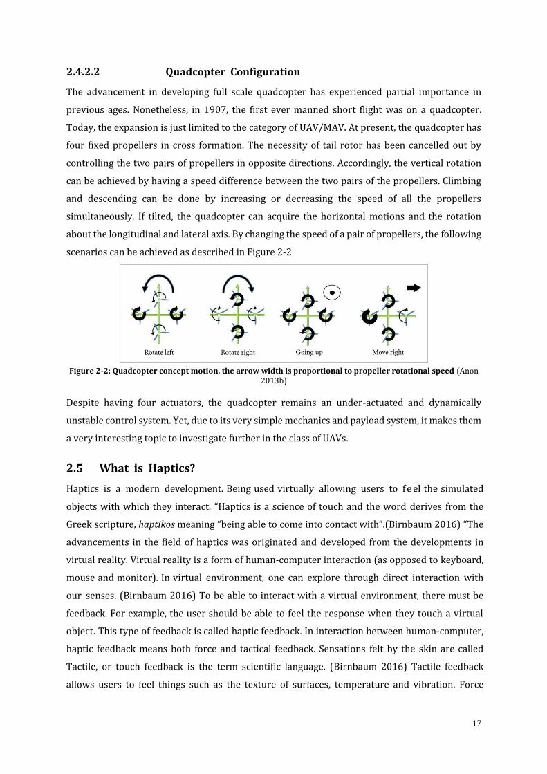
simultaneously. If tilted, the quadcopter can acquire the horizontal motions and the rotation
about the longitudinal and lateral axis. By changing the speed of a pair of propellers, the following
scenarios can be achieved as described in Figure 2-2
Figure 2-2: Quadcopter concept motion, the arrow width is proportional to propeller rotational speed (Anon
2013b)
Despite having four actuators, the quadcopter remains an under-actuated and dynamically
unstable control system. Yet, due to its very simple mechanics and payload system, it makes them
a very interesting topic to investigate further in the class of UAVs.
2.5 What is Haptics?
Haptics is a modern development. Being used virtually allowing users to f e el the simulated
objects with which they interact. “Haptics is a science of touch and the word derives from the
Greek scripture, haptikos meaning “being able to come into contact with”.(Birnbaum 2016) “The
advancements in the field of haptics was originated and developed from the developments in
virtual reality. Virtual reality is a form of human-computer interaction (as opposed to keyboard,
mouse and monitor). In virtual environment, one can explore through direct interaction with
our senses. (Birnbaum 2016) To be able to interact with a virtual environment, there must be
feedback. For example, the user should be able to feel the response when they touch a virtual
object. This type of feedback is called haptic feedback. In interaction between human-computer,
haptic feedback means both force and tactical feedback. Sensations felt by the skin are called
Tactile, or touch feedback is the term scientific language. (Birnbaum 2016) Tactile feedback
allows users to feel things such as the texture of surfaces, temperature and vibration. Force
18
feedback reproduces directional forces that can result from solid boundaries, the weight of
grasped virtual objects, mechanical compliance of an object.” (Birnbaum 2016). “Tactile
feedback, as a component of virtual reality simulations, was pioneered at MIT. In 1990 Patrick
used voice coils to provide vibrations at the fingertips of a user wearing a Dextrous Hand Master
Exoskeleton. Minsky and her colleagues developed the Sandpaper tactile joystick that mapped
image pixels to vibrations (1990).(Lam et al. 2004) Commercial tactile feedback interfaces
followed, namely the Touch Master in 1993, the CyberTouch glove in 1995, and more recently, the
FEELit Mouse in 1997. Scientists have been conducting research on haptics for decades. Goertz
at Argonne National Laboratories first used force feedback in a robotic tele-operation system for
nuclear environments in 1954.” (Lam et al. 2007) “Subsequently the group led by Brooks at the
University of North Carolina at Chapel Hill adapted the same electromechanical arm to provide
force feedback during virtual molecular docking (1990). Burdea and colleagues at Rutgers
University developed a light and portable force feedback glove called the “Rutgers Master” in
1992. Commercial force feedback devices have subsequently appeared, such as the PHANTOM
arm in 1993, the Impulse Engine in 1995 and the CyberGrasp glove in 1998.” (T. Mung Lam et al.
2009).“There clearly has been a resurgence of research interest and haptic interface products. In
addition, research on haptic feedback has been aggressively pursued in several countries outside
the U.S., notably in Japan, UK, France and Italy.” (Birnbaum 2016)
2.5.1 Prior Relevant Research on Haptic System Control
The development in Haptic system control for UAV applications has been the topic of discussion
since last two decades. But not much research has been done. Since the last decade there has been
some development, therefore new research in this field is important and required which will have
a great impact on the way haptics is sued in UAV applications.
In 2011 Lee (Lee et al. 2011) proposed a haptic control framework for UAVs over the internet by
using master-salve control option. They opted for a low level 3DOF control for UAV (Valavanis
2007; Hua et al. 2009). Omega6 (Stegagno et al. 2015) haptic controller was used and the
simulation environment was built on Orge3D engine. Ha (C. Ha & Lee 2013) proposed a video
based control framework (Claret et al. 2016) for teleoperation of UAV with haptics in 2013.
Backstepping controller (Lee, Ha, et al. 2013) and PI (Altug et al. 2005) was used for UAV control.
Omari (Omari et al. 2013) described a strategy for inexperience drone operator to perform
complex operations which provides force feedback when near any obstacles (Mahony et al. 2009;
Schill et al. 2009; Hua & Rifai 2010; Stramigioli et al. 2010; Rifai et al. 2011; Mersha et al. 2012).
They developed an artificial force field (T. M. Lam et al. 2009) environment which provides these
force feedback to the operator. The control system used was based on (Hua et al. 2009). Novint
19
Falcon was used as the choice of haptic controller and hexacopter UAV Flybox was selected. A
ROS & MATLAB/Simulink (Brandt & Colton 2010) based quadcopter control was proposed by
Grabe (Grabe et al. 2013). TeleKyb (Stegagno et al. 2015) was used to develop control for the
Force Dimensions haptic controller and quadcopter was MK-Quadro (Stegagno et al. 2015)having
simple PID with saturated integral term & backstepping controller. A bilateral (Masone et al.
2014) haptic shared control framework was given in (Niemeyer et al. 2008). Fu (Fu et al. 2016)
used concepts and models from (Stamper 1997) to develop an adjustable feedback controller on
UAV with haptic control. An enhanced teleoperation method using velocity commands for the
haptic feedback was proposed by Kanso (Kanso et al. 2015). Adaptive gain tuning controller
(Mghabghab & Asmar 2016), force-stiffness feedback controller (T. Mung Lam et al. 2009), were
also the topic of discussion in recent years (Lam et al. 2007; Lee, Franchi, et al. 2013; Brandt &
Colton 2010).
The undertaken research where the integral part is the haptic control for quadcopter UAV is a
novel control method. It consists of only one control model and software environment for the
quadcopter and the haptic control. Prior work in this field mostly contains multiple controllers
and software’s for UAV and haptics which makes customisation, optimisation and
troubleshooting quite difficult. By using a single controller and single environment, it makes the
process and optimisation easier and quicker. It also solves issues relating to control integration
between the UAV and haptic. Therefore, this makes the designed controller novel and more
suitable for applications where haptic controls are needed.
2.5.2 Haptic Controllers
Haptic controllers (or haptic interfaces) are mechanical gadgets that facilitate message between
the user and the PC. In a virtual environment, the haptic controller allows the user to get the
feeling of touch and control three-dimensional things. Since the most used computer-user
interaction devices are mouse, keyboard or a joystick, these devices are input only devices, which
mean that there is no manual feedback of the physical manipulations done between them. Due to
this the information just flows in a single direction i.e. from the device to the PC. But the haptic
devices are two way communicating devices which means when the user inputs any physical
manipulations there is a realistic feedback sent back to the user for that event. Examples of haptic
controllers includes devices for general consumer having special sensors and motors (i.e. steering
wheels, force feedback remote-controller and joysticks). Other modern gadgets developed &
designed specifically for surgical/medical applications, industrial use or other scientific
applications (e.g., GeoMagic Touch, PHANTOM Omni, Novint Falcon, etc). (Billinghurst & Furness
2015; Birnbaum 2016)
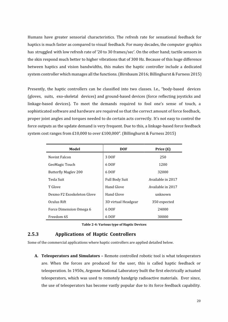
20
Humans have greater sensorial characteristics. The refresh rate for sensational feedback for
haptics is much faster as compared to visual feedback. For many decades, the computer graphics
has struggled with low refresh rate of ‘20 to 30 frames/sec’. On the other hand; tactile sensors in
the skin respond much better to higher vibrations that of 300 Hz. Because of this huge difference
between haptics and vision bandwidths, this makes the haptic controller include a dedicated
system controller which manages all the functions. (Birnbaum 2016; Billinghurst & Furness 2015)
Presently, the haptic controllers can be classified into two classes. I.e., “body-based devices
(gloves, suits, exo-skeletal devices) and ground-based devices (force reflecting joysticks and
linkage-based devices). To meet the demands required to fool one’s sense of touch, a
sophisticated software and hardware are required so that the correct amount of force feedback,
proper joint angles and torques needed to do certain acts correctly. It’s not easy to control the
force outputs as the update demand is very frequent. Due to this, a linkage-based force feedback
system cost ranges from £10,000 to over £100,000”. (Billinghurst & Furness 2015)
Model DOF Price (£)
Novint Falcon 3 DOF 250
GeoMagic Touch 6 DOF 1200
Butterfly Maglev 200 6 DOF 32000
Tesla Suit Full Body Suit Available in 2017
T Glove Hand Glove Available in 2017
Dexmo F2 Exoskeleton Glove Hand Glove unknown
Oculus Rift 3D virtual Headgear 350 expected
Force Dimension Omega 6 6 DOF 24000
Freedom 6S 6 DOF 30000
Table 2-4: Various type of Haptic Devices
2.5.3 Applications of Haptic Controllers
Some of the commercial applications where haptic controllers are applied detailed below.
A. Teleoperators and Simulators – Remote controlled robotic tool is what teleoperators
are. When the forces are produced for the user, this is called haptic feedback or
teleoperation. In 1950s, Argonne National Laboratory built the first electrically actuated
teleoperators, which was used to remotely handgrip radioactive materials. Ever since,
the use of teleoperators has become vastly popular due to its force feedback capability.
21
An every popular application of teleoperation is underwater exploration with remote
controlled devices. When a computer is used to simulate such devices, providing force
feedback is useful so that the operator feels like in actual operations. The object that is
being teleoperated does not exists in physical sense; the forces are generated using haptic
operator controls which can be stored and played again over a time by using haptic
technologies.
B. Personal Computers – The Apple’s MacBook incorporated haptic feedback into tracking
surface and “Tactile Touchpad” design with buttons in 2008. Other products like
Synaptics ClickPad followed it.
C. Tactile Electronic Displays – it is a type of display which presents information in tactile
form. The two most widespread displays are Optacon and Braille displays.
D. Virtual Reality – In virtual reality, haptics is now playing a vital role and its widely
accepted for it, due to its added sense of touch to the visual-only pre-solutions. Many of
these uses haptic rendering based on stylus, where the user uses a stylus to interface with
the virtual environment, and this makes the interaction between them as realistic as if its
real life. Nowadays, various systems are being developed for 3D designing which can give
the artist a virtual experience of real interactive modelling. A led research Hiroyuki
Shinoda at University of Tokyo, with a group of researcher developed a 3D touchable
hologram using acoustic radiation through haptic feedback, so the user hands can feel
pressure sensation.
E. Mobile Devices – the most common tactile feedback system comes in mobiles devices.
Every mobile company such as Samsung, Apple, Nokia etc. includes various types of haptic
technologies in their products, which usually comes as a vibration reaction to touch.
Another commonly used technology is PulseTouch which is generally used on car
navigation screens or other navigations systems.
F. Medical – these days’ medical simulators are being used to remotely perform surgery, for
training purposes, for interventional radiology and laparoscopy. There are many benefits
for the surgeons when performing similar kind of surgery remotely with less fatigue plus
the very well-known fact is that if a surgeon performs a particular kind of surgery many
times, it will statistically be better for his patients. Another example would be of
ophthalmology, where there are supporting springs which hold artificial lens inside the
lens capsule after the surgical removal of cataracts.
G. Robotics – The first project known as The Shadow Hand Project, which incorporates the
sense of touch, position, pressure, delicacy, strength and complexity for a human grip was
developed by Richard Greenhill and a group of researcher in London. The main aim of this
project was to develop the first convincing artificial humanoid and they were successful
22
in it. The Hand has sensors integrated in every finger and joint which sends the
information to the CPU for processing and the analysis, and then the action is performed.
This was the most promising and invaluable piece of research carried out.
H. Future Applications – There is an enormous range of future applications in haptic
controllers for human interaction with technology. Presently, the haptic technology
advancements in the field of medical, gaming, holograms, manufacturing, movies and
other industries are underway, which could change the way to operate things in future.
Due to this the medical industry is gaining vast amount of knowledge in remotely
operated health care and surgeries. It can also change the way we buy clothing item over
the internet, as the technology will allow us to feel the texture of the fabric over the
internet in near future. The future is very promising and it could create various other
opportunities in various fields which are not explored right now as they are not feasible
or realistic.
2.6 Conclusion
This chapter provides literature review on dynamics of the quadcopter, the control system of UAV
and haptics. It also investigated different type of VTOL configurations such as coaxial, helicopter
and quadcopter. Haptic was also described in detail with its use and applications available. Most
importantly this chapter defines prior research on the work in hand which is haptic system
control for UAVs. Most the haptic systems that were looked at used two different controls for the
quadcopter which made things complicated when using with haptic control. It also made
optimisation difficult and sometimes it gives large errors which are difficult to contemplate.
Therefore, in this research project, only one control system is used with the haptic control for
teleoperation of UAV which made it easier to control the quadcopter and configure the haptic
controller itself. This literature review will help us configure how haptic and quadcopter control
integrates together for the experimental and simulation part of this project. The next chapter
describes the research methodology which explains in detail about the quadcopter and haptic
modelling and development process.
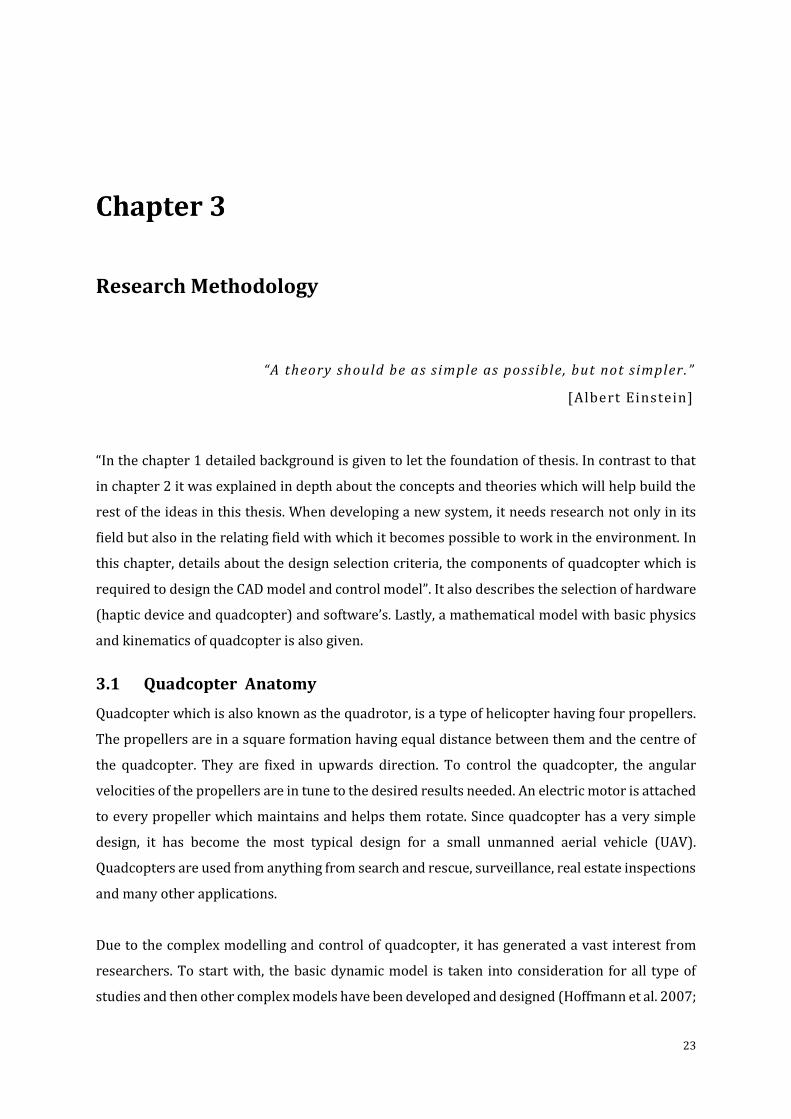
23
Research Methodology
“A theory should be as s imple as possible, but not s impler.”
[Albert Einstein]
“In the chapter 1 detailed background is given to let the foundation of thesis. In contrast to that
in chapter 2 it was explained in depth about the concepts and theories which will help build the
rest of the ideas in this thesis. When developing a new system, it needs research not only in its
field but also in the relating field with which it becomes possible to work in the environment. In
this chapter, details about the design selection criteria, the components of quadcopter which is
required to design the CAD model and control model”. It also describes the selection of hardware
(haptic device and quadcopter) and software’s. Lastly, a mathematical model with basic physics
and kinematics of quadcopter is also given.
3.1 Quadcopter Anatomy
Quadcopter which is also known as the quadrotor, is a type of helicopter having four propellers.
The propellers are in a square formation having equal distance between them and the centre of
the quadcopter. They are fixed in upwards direction. To control the quadcopter, the angular
velocities of the propellers are in tune to the desired results needed. An electric motor is attached
to every propeller which maintains and helps them rotate. Since quadcopter has a very simple
design, it has become the most typical design for a small unmanned aerial vehicle (UAV).
Quadcopters are used from anything from search and rescue, surveillance, real estate inspections
and many other applications.
Due to the complex modelling and control of quadcopter, it has generated a vast interest from
researchers. To start with, the basic dynamic model is taken into consideration for all type of
studies and then other complex models have been developed and designed (Hoffmann et al. 2007;
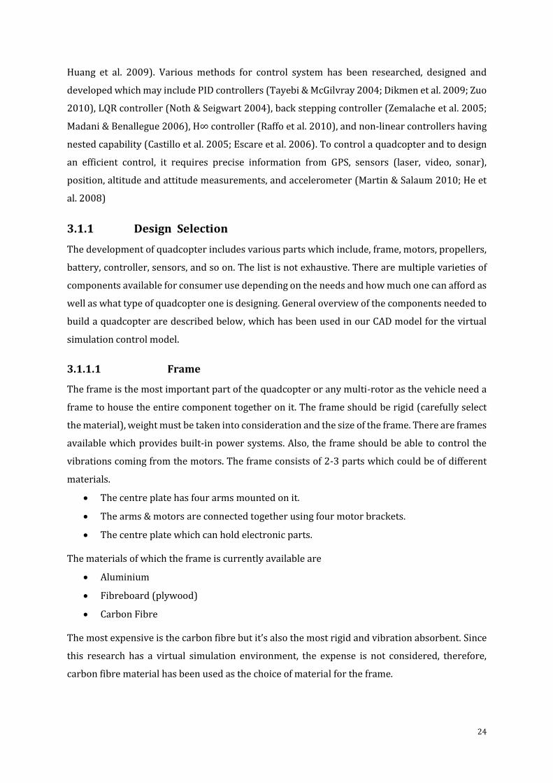
24
Huang et al. 2009). Various methods for control system has been researched, designed and
developed which may include PID controllers (Tayebi & McGilvray 2004; Dikmen et al. 2009; Zuo
2010), LQR controller (Noth & Seigwart 2004), back stepping controller (Zemalache et al. 2005;
Madani & Benallegue 2006), H∞ controller (Raffo et al. 2010), and non-linear controllers having
nested capability (Castillo et al. 2005; Escare et al. 2006). To control a quadcopter and to design
an efficient control, it requires precise information from GPS, sensors (laser, video, sonar),
position, altitude and attitude measurements, and accelerometer (Martin & Salaum 2010; He et
al. 2008)
3.1.1 Design Selection
The development of quadcopter includes various parts which include, frame, motors, propellers,
battery, controller, sensors, and so on. The list is not exhaustive. There are multiple varieties of
components available for consumer use depending on the needs and how much one can afford as
well as what type of quadcopter one is designing. General overview of the components needed to
build a quadcopter are described below, which has been used in our CAD model for the virtual
simulation control model.
3.1.1.1 Frame
The frame is the most important part of the quadcopter or any multi-rotor as the vehicle need a
frame to house the entire component together on it. The frame should be rigid (carefully select
the material), weight must be taken into consideration and the size of the frame. There are frames
available which provides built-in power systems. Also, the frame should be able to control the
vibrations coming from the motors. The frame consists of 2-3 parts which could be of different
materials.
The centre plate has four arms mounted on it.
The arms & motors are connected together using four motor brackets.
The centre plate which can hold electronic parts.
The materials of which the frame is currently available are
Aluminium
Fibreboard (plywood)
Carbon Fibre
The most expensive is the carbon fibre but it’s also the most rigid and vibration absorbent. Since
this research has a virtual simulation environment, the expense is not considered, therefore,
carbon fibre material has been used as the choice of material for the frame.
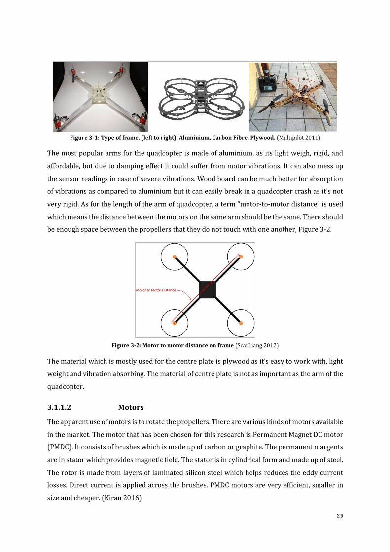
25
Figure 3-1: Type of frame. (left to right). Aluminium, Carbon Fibre, Plywood. (Multipilot 2011)
The most popular arms for the quadcopter is made of aluminium, as its light weigh, rigid, and
affordable, but due to damping effect it could suffer from motor vibrations. It can also mess up
the sensor readings in case of severe vibrations. Wood board can be much better for absorption
of vibrations as compared to aluminium but it can easily break in a quadcopter crash as it’s not
very rigid. As for the length of the arm of quadcopter, a term “motor-to-motor distance” is used
which means the distance between the motors on the same arm should be the same. There should
be enough space between the propellers that they do not touch with one another, Figure 3-2.
Figure 3-2: Motor to motor distance on frame (ScarLiang 2012)
The material which is mostly used for the centre plate is plywood as it’s easy to work with, light
weight and vibration absorbing. The material of centre plate is not as important as the arm of the
quadcopter.
3.1.1.2 Motors
The apparent use of motors is to rotate the propellers. There are various kinds of motors available
in the market. The motor that has been chosen for this research is Permanent Magnet DC motor
(PMDC). It consists of brushes which is made up of carbon or graphite. The permanent margents
are in stator which provides magnetic field. The stator is in cylindrical form and made up of steel.
The rotor is made from layers of laminated silicon steel which helps reduces the eddy current
losses. Direct current is applied across the brushes. PMDC motors are very efficient, smaller in
size and cheaper. (Kiran 2016)
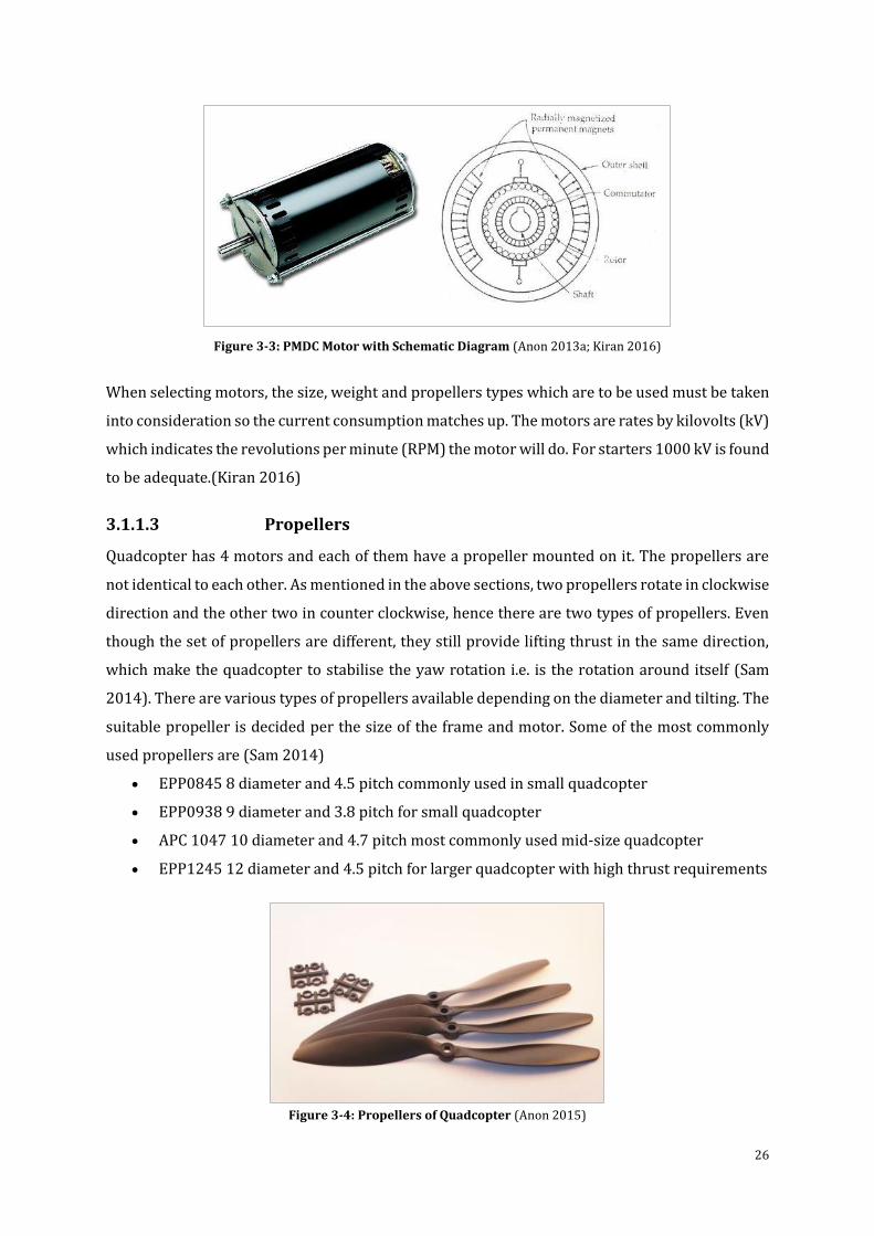
26
Figure 3-3: PMDC Motor with Schematic Diagram (Anon 2013a; Kiran 2016)
When selecting motors, the size, weight and propellers types which are to be used must be taken
into consideration so the current consumption matches up. The motors are rates by kilovolts (kV)
which indicates the revolutions per minute (RPM) the motor will do. For starters 1000 kV is found
to be adequate.(Kiran 2016)
3.1.1.3 Propellers
Quadcopter has 4 motors and each of them have a propeller mounted on it. The propellers are
not identical to each other. As mentioned in the above sections, two propellers rotate in clockwise
direction and the other two in counter clockwise, hence there are two types of propellers. Even
though the set of propellers are different, they still provide lifting thrust in the same direction,
which make the quadcopter to stabilise the yaw rotation i.e. is the rotation around itself (Sam
2014). There are various types of propellers available depending on the diameter and tilting. The
suitable propeller is decided per the size of the frame and motor. Some of the most commonly
used propellers are (Sam 2014)
EPP0845 8 diameter and 4.5 pitch commonly used in small quadcopter
EPP0938 9 diameter and 3.8 pitch for small quadcopter
APC 1047 10 diameter and 4.7 pitch most commonly used mid-size quadcopter
EPP1245 12 diameter and 4.5 pitch for larger quadcopter with high thrust requirements
Figure 3-4: Propellers of Quadcopter (Anon 2015)
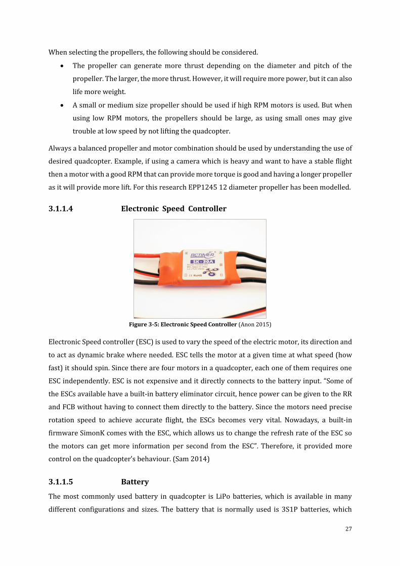
27
When selecting the propellers, the following should be considered.
The propeller can generate more thrust depending on the diameter and pitch of the
propeller. The larger, the more thrust. However, it will require more power, but it can also
life more weight.
A small or medium size propeller should be used if high RPM motors is used. But when
using low RPM motors, the propellers should be large, as using small ones may give
trouble at low speed by not lifting the quadcopter.
Always a balanced propeller and motor combination should be used by understanding the use of
desired quadcopter. Example, if using a camera which is heavy and want to have a stable flight
then a motor with a good RPM that can provide more torque is good and having a longer propeller
as it will provide more lift. For this research EPP1245 12 diameter propeller has been modelled.
3.1.1.4 Electronic Speed Controller
Figure 3-5: Electronic Speed Controller (Anon 2015)
Electronic Speed controller (ESC) is used to vary the speed of the electric motor, its direction and
to act as dynamic brake where needed. ESC tells the motor at a given time at what speed (how
fast) it should spin. Since there are four motors in a quadcopter, each one of them requires one
ESC independently. ESC is not expensive and it directly connects to the battery input. “Some of
the ESCs available have a built-in battery eliminator circuit, hence power can be given to the RR
and FCB without having to connect them directly to the battery. Since the motors need precise
rotation speed to achieve accurate flight, the ESCs becomes very vital. Nowadays, a built-in
firmware SimonK comes with the ESC, which allows us to change the refresh rate of the ESC so
the motors can get more information per second from the ESC”. Therefore, it provided more
control on the quadcopter’s behaviour. (Sam 2014)
3.1.1.5 Battery
The most commonly used battery in quadcopter is LiPo batteries, which is available in many
different configurations and sizes. The battery that is normally used is 3S1P batteries, which
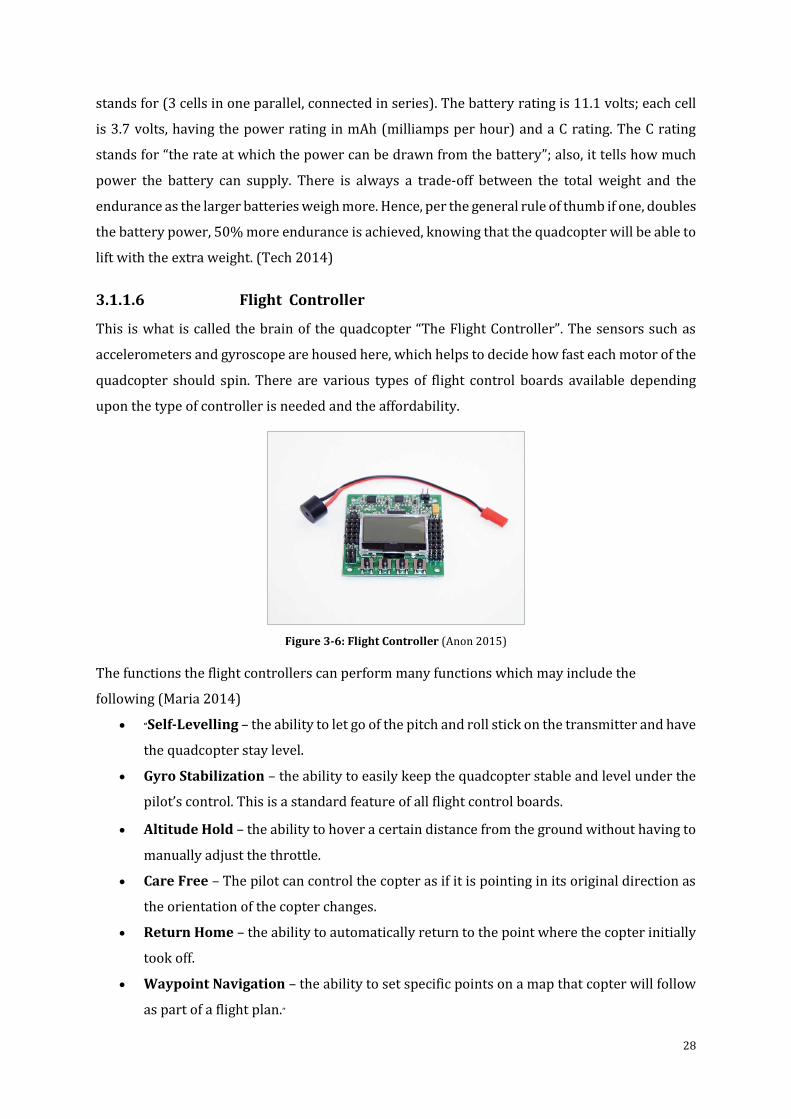
28
stands for (3 cells in one parallel, connected in series). The battery rating is 11.1 volts; each cell
is 3.7 volts, having the power rating in mAh (milliamps per hour) and a C rating. The C rating
stands for “the rate at which the power can be drawn from the battery”; also, it tells how much
power the battery can supply. There is always a trade-off between the total weight and the
endurance as the larger batteries weigh more. Hence, per the general rule of thumb if one, doubles
the battery power, 50% more endurance is achieved, knowing that the quadcopter will be able to
lift with the extra weight. (Tech 2014)
3.1.1.6 Flight Controller
This is what is called the brain of the quadcopter “The Flight Controller”. The sensors such as
accelerometers and gyroscope are housed here, which helps to decide how fast each motor of the
quadcopter should spin. There are various types of flight control boards available depending
upon the type of controller is needed and the affordability.
Figure 3-6: Flight Controller (Anon 2015)
The functions the flight controllers can perform many functions which may include the
following (Maria 2014)
“Self-Levelling – the ability to let go of the pitch and roll stick on the transmitter and have
the quadcopter stay level.
Gyro Stabilization – the ability to easily keep the quadcopter stable and level under the
pilot’s control. This is a standard feature of all flight control boards.
Altitude Hold – the ability to hover a certain distance from the ground without having to
manually adjust the throttle.
Care Free – The pilot can control the copter as if it is pointing in its original direction as
the orientation of the copter changes.
Return Home – the ability to automatically return to the point where the copter initially
took off.
Waypoint Navigation – the ability to set specific points on a map that copter will follow
as part of a flight plan.”
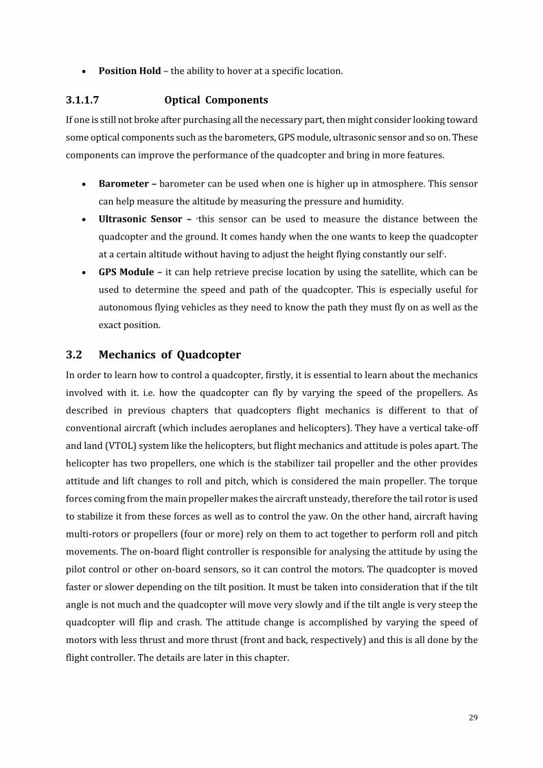
29
Position Hold – the ability to hover at a specific location.
3.1.1.7 Optical Components
If one is still not broke after purchasing all the necessary part, then might consider looking toward
some optical components such as the barometers, GPS module, ultrasonic sensor and so on. These
components can improve the performance of the quadcopter and bring in more features.
Barometer – barometer can be used when one is higher up in atmosphere. This sensor
can help measure the altitude by measuring the pressure and humidity.
Ultrasonic Sensor – “this sensor can be used to measure the distance between the
quadcopter and the ground. It comes handy when the one wants to keep the quadcopter
at a certain altitude without having to adjust the height flying constantly our self”.
GPS Module – it can help retrieve precise location by using the satellite, which can be
used to determine the speed and path of the quadcopter. This is especially useful for
autonomous flying vehicles as they need to know the path they must fly on as well as the
exact position.
3.2 Mechanics of Quadcopter
In order to learn how to control a quadcopter, firstly, it is essential to learn about the mechanics
involved with it. i.e. how the quadcopter can fly by varying the speed of the propellers. As
described in previous chapters that quadcopters flight mechanics is different to that of
conventional aircraft (which includes aeroplanes and helicopters). They have a vertical take-off
and land (VTOL) system like the helicopters, but flight mechanics and attitude is poles apart. The
helicopter has two propellers, one which is the stabilizer tail propeller and the other provides
attitude and lift changes to roll and pitch, which is considered the main propeller. The torque
forces coming from the main propeller makes the aircraft unsteady, therefore the tail rotor is used
to stabilize it from these forces as well as to control the yaw. On the other hand, aircraft having
multi-rotors or propellers (four or more) rely on them to act together to perform roll and pitch
movements. The on-board flight controller is responsible for analysing the attitude by using the
pilot control or other on-board sensors, so it can control the motors. The quadcopter is moved
faster or slower depending on the tilt position. It must be taken into consideration that if the tilt
angle is not much and the quadcopter will move very slowly and if the tilt angle is very steep the
quadcopter will flip and crash. The attitude change is accomplished by varying the speed of
motors with less thrust and more thrust (front and back, respectively) and this is all done by the
flight controller. The details are later in this chapter.
30
3.2.1 Flight Orientations
Since quadcopter are symmetrical, therefore they can fly in two different configurations (i.e. Plus
(+) and x). In x configuration, the front two motors/propellers will provide power, while in plus
(+) configuration only one of the front motor/propeller will provider power. It is discussed
further in the next section.
3.2.1.1 Axis Representation
For each of the two configurations (+, x), the coordinate system is the same. The quadcopter will
ascend and descend along z-axis, move forward and backward along x-axis and move left and
right along y-axis. (Khan 2014)
“Yaw is the rotation around z-axis, which turns the quadcopter right or left by changing
the heading as well as the direction it flies in.
Pitch is the rotation around y-axis, which allows forward and backward flying along x-
axis.
Roll is the rotation around x-axis, which allows right and left flying along y-axis.”
Figure 3-7: Axis Representation(Khan 2014)
3.2.1.2 Attitude Changes
Flight controller comes into play when attitude changes are required by the quadcopter. It
changes the speed of the motors per the user’s requirements received from the transmitter.
Helicopters and quadcopter have the same principle when it comes to stabilization and yaw
control. There are a set of each clockwise rotating motors and counter clockwise rotating motors.
Figure 3-8 shows; motor 1 & 3 are rotating clockwise and 2 & 4 are rotating counter clockwise.
The rotating counter clockwise motors recompenses for the torque and it helps the quadcopter
control in yaw rotation around the z-axis.
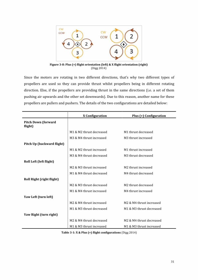
31
Since the motors are rotating in two different directions, that’s why two different types of
propellers are used so they can provide thrust whilst propellers being in different rotating
direction. Else, if the propellers are providing thrust in the same directions (i.e. a set of them
pushing air upwards and the other set downwards). Due to this reason, another name for these
propellers are pullers and pushers. The details of the two configurations are detailed below:
X Configuration Plus (+) Configuration
Pitch Down (forward flight)
M1 & M2 thrust decreased M1 thrust decreased
M3 & M4 thrust increased M3 thrust increased
Pitch Up (backward flight)
M1 & M2 thrust increased M1 thrust increased
M3 & M4 thrust decreased M3 thrust decreased
Roll Left (left flight)
M2 & M3 thrust increased M2 thrust increased
M1 & M4 thrust decreased M4 thrust decreased
Roll Right (right flight)
M2 & M3 thrust decreased M2 thrust decreased
M1 & M4 thrust increased M4 thrust increased
Yaw Left (turn left)
M2 & M4 thrust increased M2 & M4 thrust increased
M1 & M3 thrust decreased M1 & M3 thrust decreased
Yaw Right (turn right)
M2 & M4 thrust decreased M2 & M4 thrust decreased
M1 & M3 thrust increased M1 & M3 thrust increased
Table 3-1: X & Plus (+) flight configurations (Digg 2014)
Figure 3-8: Plus (+) flight orientation (left) & X flight orientation (right) (Digg 2014)
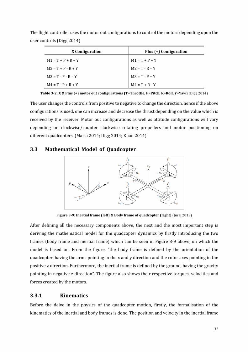
32
The flight controller uses the motor out configurations to control the motors depending upon the
user controls (Digg 2014)
X Configuration Plus (+) Configuration
M1 = T + P + R – Y M1 = T + P + Y
M2 = T + P - R + Y M2 = T - R – Y
M3 = T - P - R – Y M3 = T - P + Y
M4 = T - P + R + Y M4 = T + R - Y
Table 3-2: X & Plus (+) motor out configurations (T=Throttle, P=Pitch, R=Roll, Y=Yaw) (Digg 2014)
The user changes the controls from positive to negative to change the direction, hence if the above
configurations is used, one can increase and decrease the thrust depending on the value which is
received by the receiver. Motor out configurations as well as attitude configurations will vary
depending on clockwise/counter clockwise rotating propellers and motor positioning on
different quadcopters. (Maria 2014; Digg 2014; Khan 2014)
3.3 Mathematical Model of Quadcopter
Figure 3-9: Inertial frame (left) & Body frame of quadcopter (right) (Juraj 2013)
After defining all the necessary components above, the next and the most important step is
deriving the mathematical model for the quadcopter dynamics by firstly introducing the two
frames (body frame and inertial frame) which can be seen in Figure 3-9 above, on which the
model is based on. From the figure, “the body frame is defined by the orientation of the
quadcopter, having the arms pointing in the x and y direction and the rotor axes pointing in the
positive z direction. Furthermore, the inertial frame is defined by the ground, having the gravity
pointing in negative z direction”. The figure also shows their respective torques, velocities and
forces created by the motors.
3.3.1 Kinematics
Before the delve in the physics of the quadcopter motion, firstly, the formalisation of the
kinematics of the inertial and body frames is done. The position and velocity in the inertial frame
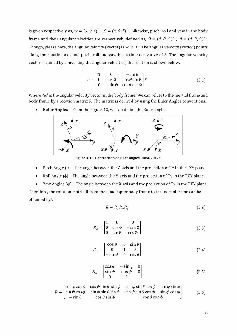
33
is given respectively as, “𝑥 = (𝑥, 𝑦, 𝑧)𝑇 , �� = (��, ��, ��)𝑇”. Likewise, pitch, roll and yaw in the body
frame and their angular velocities are respectively defined as, “𝜃 = (𝜙, 𝜃, 𝜓)𝑇 , �� = (𝜙, ��, ��)𝑇”.
Though, please note, the angular velocity (vector) is “𝜔 ≠ ��”. The angular velocity (vector) points
along the rotation axis and pitch, roll and yaw has a time derivative of 𝜃. The angular velocity
vector is gained by converting the angular velocities; the relation is shown below.
𝜔 = [
1 0 − sin𝜃0 cos∅ cos 𝜃 sin∅0 − sin∅ cos𝜃 cos∅
] ��
(3.1)
Where “‘𝜔’ is the angular velocity vector in the body frame. We can relate to the inertial frame and
body frame by a rotation matrix R. The matrix is derived by using the Euler Angles conventions.
Euler Angles – From the Figure 42, we can define the Euler angles
Figure 3-10: Contraction of Euler angles (Anon 2012a)
Pitch Angle () – The angle between the Z-axis and the projection of Tz in the TXY plane.
Roll Angle () – The angle between the Y-axis and the projection of Ty in the TXY plane.
Yaw Angles () – The angle between the X-axis and the projection of Tx in the TXY plane.
Therefore, the rotation matrix R from the quadcopter body frame to the inertial frame can be
obtained by”:
𝑅 = 𝑅𝑥𝑅𝑦𝑅𝑧 (3.2)
𝑅𝑥 = [
1 0 00 cos∅ − sin∅0 sin∅ cos∅
]
(3.3)
𝑅𝑥 = [
cos 𝜃 0 sin𝜃0 1 0
− sin𝜃 0 cos 𝜃]
(3.4)
𝑅𝑥 = [
cos𝜓 − sin𝜓 0sin𝜓 cos𝜓 0
0 0 1
]
(3.5)
𝑅 = [
cos𝜓 𝑐𝑜𝑠𝜙 cos𝜓 sin𝜃 sin𝜙sin𝜓 𝑐𝑜𝑠𝜙 sin𝜓 sin 𝜃 sin𝜙
−sin 𝜃 cos 𝜃 sin𝜙
cos𝜓 sin 𝜃 cos𝜙 + sin𝜓 sin𝜙sin𝜓 sin𝜃 cos𝜙 − sin𝜙 cos𝜓
cos𝜃 cos𝜙]
(3.6)
34
3.3.2 Physics
To model the complete dynamics model of the quadcopter, it’s necessary to understand the
physical properties that manages it. Firstly, the motors: the description of how they are used by
the quadcopter, followed by the use of energy, which will help us to understand the forces and
thrusts of the motors produced by the quadcopter. Since all the motors are similar on the
quadcopter, analysing anyone of them is enough. Also, a set of propellers are like each other and
they rotate in either clockwise direction or counter clockwise direction. If one propeller is
rotating clockwise then the two adjacent to it will rotate counter clockwise, so that the torque
generated is balanced if all the propellers are rotating at the same speed.
3.3.2.1 Motors
Since PMDC motors are used in this research quadcopters, the torque produced by them are given
by,
𝜏 = 𝐾𝑡(𝐼 − 𝐼0) (3.7)
Where I and Io are input current and current when there is no load on the motor, Kt is the torque
proportionality constant and 𝜏 is the motor torque. The voltage across the motor is sum of the
back-EMF and some resistive loss which is given by, (Castillo, 2005)
𝑉 = 𝐼 𝑅𝑚 + 𝐾𝑣𝜔 (3.8)
Where 𝜔 is the angular velocity of the motor, Kv is the proportionality constant (back-EMF
generated per RPM) Rm is the motor resistance and V is the voltage drop across the motor.
Therefore, it can be used to calculate the power used by the quadcopter, which is given by,
(Castillo, 2005)
𝑃 = 𝐼𝑉 =
(𝜏 + 𝐾𝑡𝐼0)(𝐾𝑡𝐼0𝑅𝑚 + 𝜏𝑅𝑚 + 𝐾𝑡𝐾𝑣𝜔)
𝐾𝑡2
(3.9)
Because of the simple model used here, it can be assumed that the motor resistance is negligible.
Hence the angular velocity becomes proportional to power, and it’s given by,
𝑃 ≈
(𝜏 + 𝐾𝑡𝐼0)𝐾𝑣𝜔
𝐾𝑡
(3.10)
Also, assume for simplicity that KtIa ≪ 𝜏. Since Io is the current when there is no load and there is
very small, therefore it’s not irrational to assume this. Hence the final equation for power is given
by
𝑃 ≈
𝐾𝑣
𝐾𝑡𝜏𝜔
(3.11)
35
3.3.2.2 Forces
To keep the quadcopter flying power is needed. “Since, the energy the motor spends in a given
time is equal to the force generated on the propeller times the distance that the air it displaces
moves. Also, power is equal to the thrust times the air velocity”. (Castillo et al. 2005)
𝑃. 𝑑 𝑡 = 𝐹. 𝑑 𝑥 (3.12)
𝑃 = 𝐹 𝑑 𝑥
𝑑 𝑡
(3.13)
𝑃 = 𝑇𝑣ℎ (3.14)
It is assumed that “the free stream velocity, 𝑣∞”, is zero (means that there is no air present in the
surrounding environment), also assume that the speed of the quadcopter is slow, so vh is the air
velocity when its hovering. Therefore, the “momentum theory” gives us the equation for the
hovering velocity of the quadcopter as a function of thrust (Castillo et al. 2005; Huang et al. 2009)
𝑣ℎ = √
𝑇
2𝜌𝐴
(3.15)
Where “A is the area swept out” buy the propeller, and “𝜌 is the density of the surrounding air”.
Using the simplified equation of power,
𝑃 = 𝐾𝑣
𝐾𝑡 𝜏𝜔 =
𝐾𝑣𝐾𝑡
𝐾𝑡 𝑇𝜔 =
𝑇32
√2𝜌𝐴
(3.16)
Further solving the above equation for thrust magnitude T,
𝑇 = (
𝐾𝑣𝐾𝑡√2𝜌𝐴
𝐾𝑡𝜔)
2
= 𝑘𝜔2 (3.17)
Where square of angular velocity of the motor is proportional to thrust and k is some applicably
dimensioned constant. Therefore, after summing up all the motors, the total thrust in the body
frame is given as”,
𝑇𝐵 = Σ𝑖=1
4 𝑇𝑖 = 𝑘 [00
Σ𝜔12]
(3.18)
Furthermore, for the thrust force, modelling the friction (“force which is proportional to the linear
velocity in each direction”) can be done. To do this, model three different friction constants for
each direction of motion and the friction model should be in the body frame.
3.3.2.3 Torques
The next step after computing the forces is to compute the torques. About the z-axis, some torque
is contributed from each of the motors. Where this torque is responsible for providing thrust as
36
well as keeping the propellers rotating. It overcomes the drag forces and creates instantaneous
angular acceleration. The friction force can be obtained by the drag equation from fluid dynamics,
which is given as,
𝐹𝐷 =
1
2 𝜌𝐶𝐷𝐴𝑣2
(3.19)
Where “A is the reference area (it’s the propeller cross-section and not the area swept out by the
propeller)”, CD is the “dimensionless constant” and 𝜌 is the surrounding fluid density. Therefore,
the torque due to drag is given by,
𝜏𝐷 =
1
2 𝑅𝜌𝐶𝐷𝐴𝑣2 =
1
2 𝑅𝜌𝐶𝐷𝐴(𝜔𝑅)2 = 𝑏𝜔2
(3.20)
Where b is dimensioned constant, “R is the radius of the propeller and 𝜔 is the angular velocity
of the propeller”. Therefore, the complete equation of torque about the z-axis for the ith motor is
given by,
𝜏2 = 𝑏𝜔2 + 𝐼𝑀�� (3.21)
Where “�� is the angular acceleration of the propeller, IM is the moment of inertia about the motor
z-axis and b is the drag coefficient.” �� ≈ 0 for a steady state flight, which is not landing or take-
off. This is because the propellers will maintain almost constant thrust and will not be
accelerating. Hence, by ignoring the term, the simplified equation can be given as,
𝜏𝑧 = (−1)𝑖+1 𝑏𝜔𝑖2 (3.22)
Depending on the rotation of the propeller I.e. clockwise or counter clockwise, the term (-1)i+1
will be positive or negative respectively. So, by summing up all the torques from each propeller
we could get the total torque, which is given by,
𝜏𝜓 = 𝑏 (𝜔12 − 𝜔2
2 + 𝜔32 − 𝜔4
2) (3.23)
From the standard mechanics, pitch and roll torques can be found. By choosing the motor i=1 &
3 to be on the roll axis, the equations will be given as,
𝜏𝜙 = Σ 𝑟 𝑥 𝑇 = 𝐿 (𝑘𝜔12 − 𝑘𝜔3
2) = 𝐿𝑘 (𝜔12 − 𝜔3
2) (𝑟𝑜𝑙𝑙) (3.24)
𝜏𝜃 = 𝐿𝑘 (𝜔22 − 𝜔4
2) (𝑝𝑖𝑡𝑐ℎ) (3.25)
The distance between any given propeller and the centre of the quadcopter is given by L.
therefore summing all together, the torques in the body frame are given by
𝜏𝐵 = [
𝐿𝑘(𝜔12 − 𝜔3
2)
𝐿𝑘(𝜔22 − 𝜔4
2
𝑏((𝜔12 − 𝜔2
2 + (𝜔32 − 𝜔4
2)
]
(3.26)
Now all the parts required to design the dynamics of the quadcopter have been derived. They will
be enhanced further and described later in the report when the advanced model designed.
37
3.3.2.4 Equation of Motion
Due to gravity, thrust and linear friction, the quadcopter can accelerate, in the inertial frame. To
obtain the thrust vector, the rotation matrix R can be used, which can map the thrust vector from
the body frame to inertial frame. Therefore, the linear motion can be give as, (Hoffmann et al.
2007)
𝑚�� = [
00
−𝑚𝑔] + 𝑅𝑇𝐵 + 𝐹𝐷
(3.27)
Where FD. and TB are the drag force and thrust vector (body frame) respectively, “g is the
acceleration due to gravity” and �� is the position of the quadcopter.
Since the linear equations of motion are appropriate for the inertial frame, similarly, the
rotational equations of motion are appropriate for the body frame, which will help us to get
rotations about the quadcopter centre rather than inertial frame. By using the Euler equations for
rigid body, the rotational equations are obtained, which is given in vector form as,
𝐼�� + 𝜔 × (𝐼𝜔) = 𝜏 (3.28)
By reworking the above equation, (Hoffmann et al. 2007)
�� = [
��𝑥
��𝑦
��𝑧
] = 𝐼−1(𝜏 − 𝜔 × (𝐼𝜔))
(3.29)
To model the quadcopter for initial phase, consider there are two uniform shafts crossed at the
origin having a motor at each of the four ends. Therefore, the result in a diagonal inertia matrix
can be given by,
𝐼 = [
𝐼𝑥𝑥 00 𝐼𝑦𝑦
0 0
00𝐼𝑧𝑧
]
(3.30)
Hence, the rotational equations of motion for the body frame can be given as,
�� = [
𝜏𝜙𝐼𝑥𝑥−1
𝜏𝜃𝐼𝑦𝑦−1
𝜏𝜓𝐼𝑧𝑧−1
] −
[ 𝐼𝑦𝑦 − 𝐼𝑧𝑧
𝐼𝑥𝑥𝜔𝑦𝜔𝑧
𝐼𝑧𝑧 − 𝐼𝑥𝑥
𝐼𝑦𝑦𝜔𝑥𝜔𝑧
𝐼𝑥𝑥 − 𝐼𝑦𝑦
𝐼𝑧𝑧𝜔𝑥𝜔𝑦]
(3.31)
3.4 Selection of Hardware
In this section, the hardware components used in this project has been discussed. Firstly, the
quadcopter which is used in this project to do experiments in real time using the haptic devices
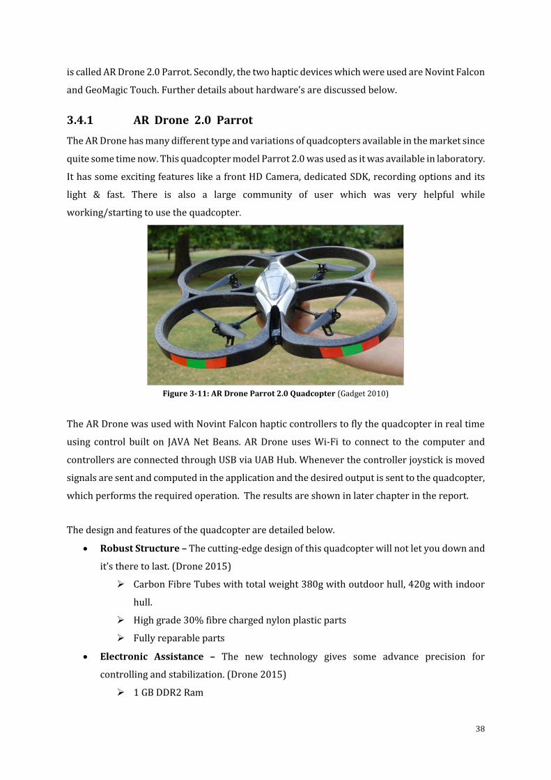
38
is called AR Drone 2.0 Parrot. Secondly, the two haptic devices which were used are Novint Falcon
and GeoMagic Touch. Further details about hardware’s are discussed below.
3.4.1 AR Drone 2.0 Parrot
The AR Drone has many different type and variations of quadcopters available in the market since
quite some time now. This quadcopter model Parrot 2.0 was used as it was available in laboratory.
It has some exciting features like a front HD Camera, dedicated SDK, recording options and its
light & fast. There is also a large community of user which was very helpful while
working/starting to use the quadcopter.
Figure 3-11: AR Drone Parrot 2.0 Quadcopter (Gadget 2010)
The AR Drone was used with Novint Falcon haptic controllers to fly the quadcopter in real time
using control built on JAVA Net Beans. AR Drone uses Wi-Fi to connect to the computer and
controllers are connected through USB via UAB Hub. Whenever the controller joystick is moved
signals are sent and computed in the application and the desired output is sent to the quadcopter,
which performs the required operation. The results are shown in later chapter in the report.
The design and features of the quadcopter are detailed below.
Robust Structure – The cutting-edge design of this quadcopter will not let you down and
it’s there to last. (Drone 2015)
Carbon Fibre Tubes with total weight 380g with outdoor hull, 420g with indoor
hull.
High grade 30% fibre charged nylon plastic parts
Fully reparable parts
Electronic Assistance – The new technology gives some advance precision for
controlling and stabilization. (Drone 2015)
1 GB DDR2 Ram
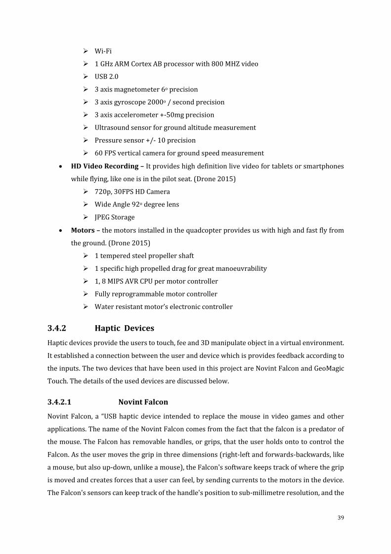
39
Wi-Fi
1 GHz ARM Cortex AB processor with 800 MHZ video
USB 2.0
3 axis magnetometer 6o precision
3 axis gyroscope 2000o / second precision
3 axis accelerometer +-50mg precision
Ultrasound sensor for ground altitude measurement
Pressure sensor +/- 10 precision
60 FPS vertical camera for ground speed measurement
HD Video Recording – It provides high definition live video for tablets or smartphones
while flying, like one is in the pilot seat. (Drone 2015)
720p, 30FPS HD Camera
Wide Angle 92o degree lens
JPEG Storage
Motors – the motors installed in the quadcopter provides us with high and fast fly from
the ground. (Drone 2015)
1 tempered steel propeller shaft
1 specific high propelled drag for great manoeuvrability
1, 8 MIPS AVR CPU per motor controller
Fully reprogrammable motor controller
Water resistant motor’s electronic controller
3.4.2 Haptic Devices
Haptic devices provide the users to touch, fee and 3D manipulate object in a virtual environment.
It established a connection between the user and device which is provides feedback according to
the inputs. The two devices that have been used in this project are Novint Falcon and GeoMagic
Touch. The details of the used devices are discussed below.
3.4.2.1 Novint Falcon
Novint Falcon, a “USB haptic device intended to replace the mouse in video games and other
applications. The name of the Novint Falcon comes from the fact that the falcon is a predator of
the mouse. The Falcon has removable handles, or grips, that the user holds onto to control the
Falcon. As the user moves the grip in three dimensions (right-left and forwards-backwards, like
a mouse, but also up-down, unlike a mouse), the Falcon's software keeps track of where the grip
is moved and creates forces that a user can feel, by sending currents to the motors in the device.
The Falcon's sensors can keep track of the handle's position to sub-millimetre resolution, and the
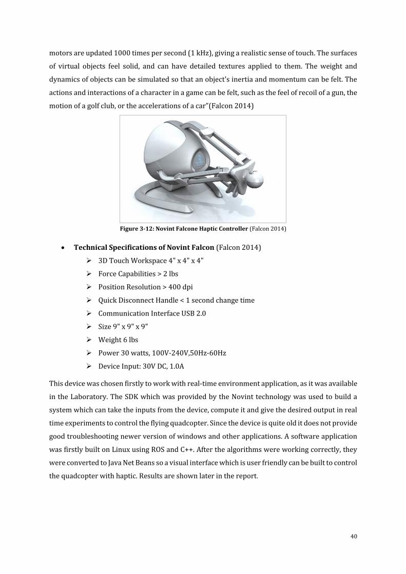
40
motors are updated 1000 times per second (1 kHz), giving a realistic sense of touch. The surfaces
of virtual objects feel solid, and can have detailed textures applied to them. The weight and
dynamics of objects can be simulated so that an object's inertia and momentum can be felt. The
actions and interactions of a character in a game can be felt, such as the feel of recoil of a gun, the
motion of a golf club, or the accelerations of a car”(Falcon 2014)
Figure 3-12: Novint Falcone Haptic Controller (Falcon 2014)
Technical Specifications of Novint Falcon (Falcon 2014)
3D Touch Workspace 4" x 4" x 4"
Force Capabilities > 2 lbs
Position Resolution > 400 dpi
Quick Disconnect Handle < 1 second change time
Communication Interface USB 2.0
Size 9" x 9" x 9"
Weight 6 lbs
Power 30 watts, 100V-240V,50Hz-60Hz
Device Input: 30V DC, 1.0A
This device was chosen firstly to work with real-time environment application, as it was available
in the Laboratory. The SDK which was provided by the Novint technology was used to build a
system which can take the inputs from the device, compute it and give the desired output in real
time experiments to control the flying quadcopter. Since the device is quite old it does not provide
good troubleshooting newer version of windows and other applications. A software application
was firstly built on Linux using ROS and C++. After the algorithms were working correctly, they
were converted to Java Net Beans so a visual interface which is user friendly can be built to control
the quadcopter with haptic. Results are shown later in the report.
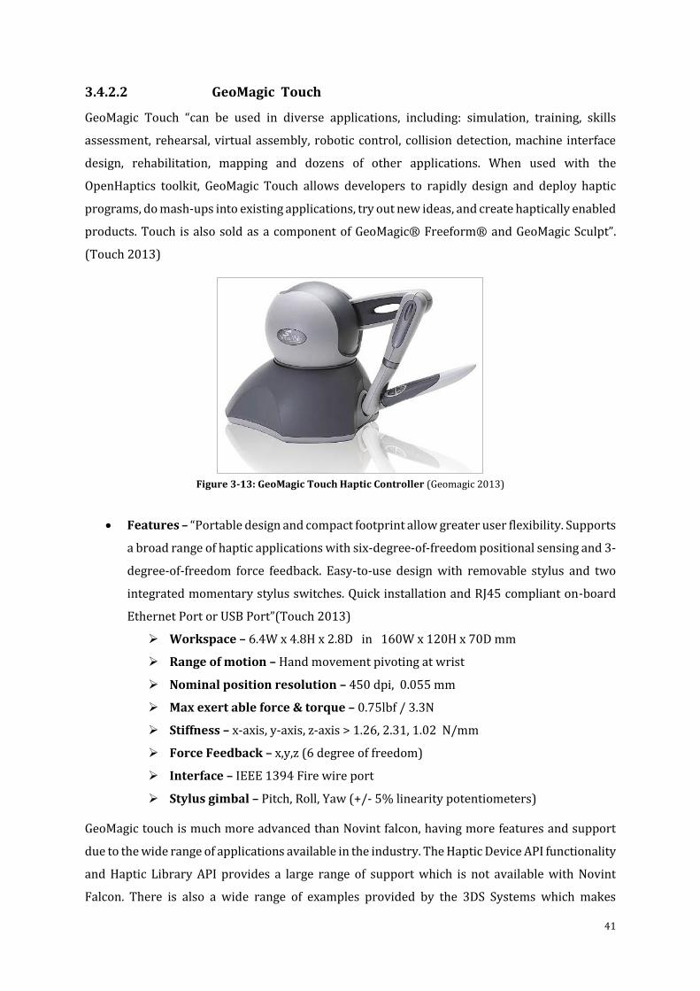
41
3.4.2.2 GeoMagic Touch
GeoMagic Touch “can be used in diverse applications, including: simulation, training, skills
assessment, rehearsal, virtual assembly, robotic control, collision detection, machine interface
design, rehabilitation, mapping and dozens of other applications. When used with the
OpenHaptics toolkit, GeoMagic Touch allows developers to rapidly design and deploy haptic
programs, do mash-ups into existing applications, try out new ideas, and create haptically enabled
products. Touch is also sold as a component of GeoMagic® Freeform® and GeoMagic Sculpt”.
(Touch 2013)
Figure 3-13: GeoMagic Touch Haptic Controller (Geomagic 2013)
Features – “Portable design and compact footprint allow greater user flexibility. Supports
a broad range of haptic applications with six-degree-of-freedom positional sensing and 3-
degree-of-freedom force feedback. Easy-to-use design with removable stylus and two
integrated momentary stylus switches. Quick installation and RJ45 compliant on-board
Ethernet Port or USB Port”(Touch 2013)
Workspace – 6.4W x 4.8H x 2.8D in 160W x 120H x 70D mm
Range of motion – Hand movement pivoting at wrist
Nominal position resolution – 450 dpi, 0.055 mm
Max exert able force & torque – 0.75lbf / 3.3N
Stiffness – x-axis, y-axis, z-axis > 1.26, 2.31, 1.02 N/mm
Force Feedback – x,y,z (6 degree of freedom)
Interface – IEEE 1394 Fire wire port
Stylus gimbal – Pitch, Roll, Yaw (+/- 5% linearity potentiometers)
GeoMagic touch is much more advanced than Novint falcon, having more features and support
due to the wide range of applications available in the industry. The Haptic Device API functionality
and Haptic Library API provides a large range of support which is not available with Novint
Falcon. There is also a wide range of examples provided by the 3DS Systems which makes
42
development easier. The idea of buying this device was considered because of the requirements
of the project, and because it was the only device available which had 6 degrees of freedom (DOF)
which was fitting in the project budget. Other haptic devices were also considered but were very
expensive. GeoMagic also has an amazing windows’ (Microsoft OS) based functionality as
compared to Novint Falcon and its SDK. This device was used for the control based on
MATLAB/Simulink for virtual simulation environment application for controlling the quadcopter
using haptic device. The SDK of Novint Falcon was not supported by never version of graphics
drivers which were required for the simulation environment and it also had limitations with JAVA
ad there is no support available from the developers of the SDK or Novint Falcon. Therefore, two
different haptic controllers had to be used. The results are shown later in the report.
3.5 Selection of Software
As already established that to control robots (in my case a quadcopter and haptic controller) one
is required to build controls which will enable the human to communicate with the machine, as
the machine does not understand human language. The control will translate the human
requirements into machine readable language so the desired output can be achieved.
In this project, a quadcopter is controlled using haptic controllers and therefore controls were
written using applications for respected hardware. For controlling the quadcopter with GeoMagic
Touch in virtual environment, control was developed in MATLAB/Simulink. For controlling the
AR Drone with Novint Falcon in real time experiment, Java Net Beans 8.0 was used. Details of the
software selection are discussed below.
3.5.1 Java Net Beans
From the requirements of this project, it was concluded that there is a need of multiple platforms
to achieve the desired work (real-time and virtual simulation experiments). For the first part of
the project, ROS is used with JAVA Net Beans for the real-time experiments. JAVA was considered
because of my vast experience working with it. It’s a very user friendly application providing
various types of built-in functions which makes development easier.
Features
Simple & Easy to write and compile
Open Source
Object Oriented
Robust
Portable (platform independent)
43
3.5.2 Robot Operating System (ROS)
“ROS is an open-source, meta-operating system for your robot. It provides the services one would
expect from an operating system, including hardware abstraction, low-level device control,
implementation of commonly-used functionality, message-passing between processes, and
package management. It also provides tools and libraries for obtaining, building, writing, and
running code across multiple computers. ROS is similar in some respects to 'robot frameworks,'
such as YARP, CARMEN, Orca, and Microsoft Robotics Studio.” The ROS runtime "graph" is a peer-
to-peer network of processes (potentially distributed across machines) that are loosely coupled
using the ROS communication infrastructure. (WikiRos 2013). ROS also has seamless integration
with various software’s which makes it easier to connect with. (WikiRos 2013). ROS was used
initially to write a script for the AR Drone and Haptic for communication purposes between them.
Soon after the initial code was developed it was then transferred to JAVA because it’s easier to
work in. Therefore, all the rest of control for AR Drone and Haptic was developed in JAVA using
API & SDK.
3.5.3 MATLAB & Simulink
The second part of the project is based on controlling the quadcopter with haptic device in virtual
environment. To do this, MATLAB and Simulink were selected to design the control for the
quadcopter having a virtual simulation environment. After successfully designing and running
the control, haptic device (GeoMagic Touch) controls were implemented with it.
MATLAB –“(matrix laboratory) is a multi-paradigm numerical computing environment
and fourth-generation programming language. A proprietary programming language
developed by MathWorks, MATLAB allows matrix manipulations, plotting of functions
and data, implementation of algorithms, creation of user interfaces, and interfacing with
programs written in other languages, including C, C++, Java, Fortran and Python. Although
MATLAB is intended primarily for numerical computing, an optional toolbox uses the
MuPAD symbolic engine, allowing access to symbolic computing capabilities. An
additional package, Simulink, adds graphical multi-domain simulation and model-based
design for dynamic and embedded systems. The MATLAB application is built around the
MATLAB scripting language. Common usage of the MATLAB application involves using
the Command Window as an interactive mathematical shell or executing text files
containing MATLAB code”.(MathWorks 2012)
SIMULINK – “is developed by MathWorks, is a graphical programming environment for
modelling, simulating and analysing multi-domain dynamic systems. Its primary interface
44
is a graphical block diagramming tool and a customizable set of block libraries.” It offers
tight integration with the rest of the MATLAB environment and can either drive MATLAB
or be scripted from it. Simulink is widely used in automatic control and digital signal
processing for multi-domain simulation and Model-Based Design. MathWorks and other
third-party hardware and software products can be used with Simulink. For example,
state-flow extends Simulink with a design environment for developing state machines and
flow charts. MathWorks claims that, coupled with another of their products, Simulink can
automatically generate C source code for real-time implementation of systems. As the
efficiency and flexibility of the code improves, this is becoming more widely adopted for
production systems, in addition to being a tool for embedded system design work because
of its flexibility and capacity for quick iteration [citation needed]. Embedded Coder
creates code efficient enough for use in embedded systems. (MathWorks 2012)
The integration of MATLAB/Simulink with JAVA and ROS makes it very useful and efficient. It
makes troubleshooting easier and execution faster. It also makes the process platform
independent and everything can be done using a single software after integration is done.
MATLAB/Simulink has been widely developed for aerospace industry therefore many
components of UAV control are available as built-in functions. Also since MATLAB/Simulink has
a large community, therefore, the support available is excellent. This is why MATLAB/Simulink
has chosen as the preferred software for this research project.
3.5.4 SolidWorks
SolidWorks is computer aided engineering (CAE) and computer aided design (CAD) software
application with runs of Windows. The software has very advance designing capabilities in the
field do aerospace and robotics. It is one of the most widely used software by engineers from
various field which included, aerospace, robotics, mechanical engineering, civil engineering and
so on.
To build the virtual simulation environment in MATLAB and the CAD model for quadcopter for
the controlling purposes, solid works 2010 was used for designing process. When the model was
finalised, it was then used with the control of quadcopter by integrating it with MATLAB/
Simulink. To view all the components of the quadcopter, see Appendix I. Also, to view the process
of how to integrate solid works with MATLAB/Simulink see Appendix III.
When the CAD model of the quadcopter is integrated into MATLAB/Simulink it creates the
complete control model for the quadcopter and all the dynamics equations are derived
45
automatically. Although, this a very useful technique to build controls for a quadcopter, it
sometimes gives error if the model is not correctly defined in Solid works. There were a couple of
instances when the CAD model was integrated with MATLAB/Simulink it wrongly derived the
motors and propeller controls. This was due the definition was wrongly defined in the CAD model.
Furthermore, the virtual environment was also included with the CAD model rather than
designing it separately again in MATLAB.
3.6 Conclusion
This chapter concludes the research methodology for this research project. It described the
quadcopter anatomy including the designing of components of the quadcopter. Which were used
in the development of CAD model of quadcopter for the virtual simulation environment.
Furthermore, the basic concept of the flight configurations and the mechanics of the quadcopter
were described. The mathematical model of a basic quadcopter was described so later when the
advanced model is built it can be used and optimised accordingly. Some of the mentioned
equations in this sections are general and others are derived from the model itself which was
obtained when the CAD model was integrated with MATLAB/Simulink. Newer version of
MATLAB provides techniques from which we can obtain equations from the Simulink block
directly from the software, rather than producing it yourself. These new software’s has made it
quicker and easier to develop controls, virtual environments and configure them at a single
platform. This was not possible some years back or in prior versions of the used software’s, when
one needed to develop each of the steps separately using different tools which is very time
consuming and expensive and one needs to have good knowledge of the different software’s
needed to develop all the required components for a simulation based controls. Finally,
hardware’s (Haptic Devices: Novint Falcon & GeoMagic Touch. & AR Drone) were defined to state
their purpose and how they were selected for this project. Furthermore, the software’s selection
was also presented which was used in this project for development of real-time experiments &
virtual simulations environment and solid works for the development of quadcopter CAD model.
In the next chapter the development of the advanced system control and haptic control is
presented with integration and testing for the undertaken research project.
46
Design Methodology
“Nothing shocks me, I ’m a scientist .”
[Harrison Ford as Indiana Jones]
In chapter 3 research methodology was discussed based on the theories and concepts from the
field of robotics and UAV technology. To design and develop the stated idea, the concept of design
and its fabrication must be stated, as well as the mechanical and system designing. In this chapter,
the design methodology is discussed including the control system used and the haptic system
controls. Furthermore, the phase of integration and testing is also defined so when the system is
developed, it could be done without going back to do research.
4.1 Design Concept
The author has mentioned the two concepts in (Akhtar 2013). When a system is designed, there
are normally two (2) approaches that followed:
The Top to Down Approach
The Bottom to Up Approach
“The top-down approach is also known as deductive reasoning. This method helps in breaking
down the main system into subsystems to gain the insights of it. In this method, an overview of
the system is first defined leaving out the details of the first level subsystems (Akhtar 2013). Then
each subsystem is redefined in depth and in detail until the entire understanding is reduced to
base elements. In other words, this method starts with the complete picture and then it breaks
down into smaller divisions. (Akhtar 2013)
The bottom-up approach is also known as inductive reasoning. This method uses small systems
and brings them together to form a large system. It is based on the incoming data from the
environment to form a perception. In this method, the small system detailing is done first in depth
then these systems are linked together to form a large system and therefore it continues to link
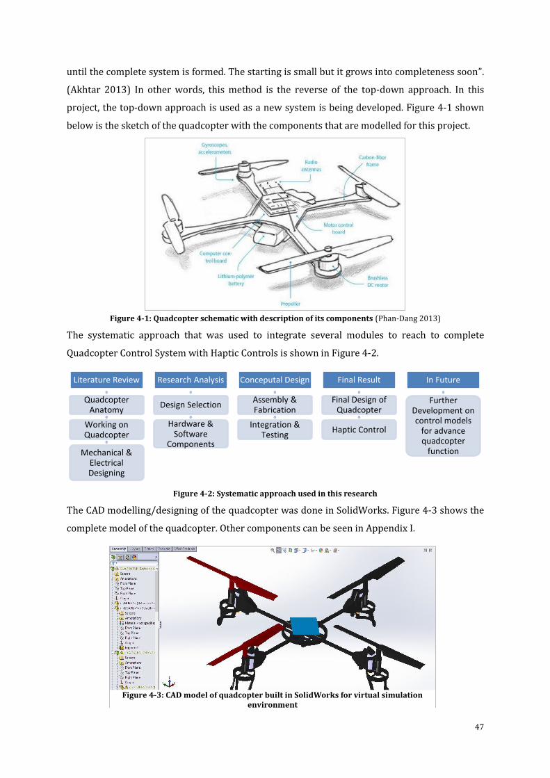
47
until the complete system is formed. The starting is small but it grows into completeness soon”.
(Akhtar 2013) In other words, this method is the reverse of the top-down approach. In this
project, the top-down approach is used as a new system is being developed. Figure 4-1 shown
below is the sketch of the quadcopter with the components that are modelled for this project.
Figure 4-1: Quadcopter schematic with description of its components (Phan-Dang 2013)
The systematic approach that was used to integrate several modules to reach to complete
Quadcopter Control System with Haptic Controls is shown in Figure 4-2.
Figure 4-2: Systematic approach used in this research
The CAD modelling/designing of the quadcopter was done in SolidWorks. Figure 4-3 shows the
complete model of the quadcopter. Other components can be seen in Appendix I.
Literature Review
Quadcopter Anatomy
Working on Quadcopter
Mechanical & Electrical Designing
Research Analysis
Design Selection
Hardware & Software
Components
Conceputal Design
Assembly & Fabrication
Integration & Testing
Final Result
Final Design of Quadcopter
Haptic Control
In Future
Further Development on control models
for advance quadcopter
function
Figure 4-3: CAD model of quadcopter built in SolidWorks for virtual simulation environment
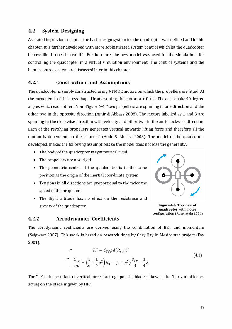
48
4.2 System Designing
As stated in previous chapter, the basic design system for the quadcopter was defined and in this
chapter, it is further developed with more sophisticated system control which let the quadcopter
behave like it does in real life. Furthermore, the new model was used for the simulations for
controlling the quadcopter in a virtual simulation environment. The control systems and the
haptic control system are discussed later in this chapter.
4.2.1 Construction and Assumptions
The quadcopter is simply constructed using 4 PMDC motors on which the propellers are fitted. At
the corner ends of the cross shaped frame setting, the motors are fitted. The arms make 90 degree
angles which each other. From Figure 4-4, “two propellers are spinning in one direction and the
other two in the opposite direction (Amir & Abbass 2008). The motors labelled as 1 and 3 are
spinning in the clockwise direction with velocity and other two in the anti-clockwise direction.
Each of the revolving propellers generates vertical upwards lifting force and therefore all the
motion is dependent on these forces” (Amir & Abbass 2008). The model of the quadcopter
developed, makes the following assumptions so the model does not lose the generality:
The body of the quadcopter is symmetrical rigid
The propellers are also rigid
The geometric centre of the quadcopter is in the same
position as the origin of the inertial coordinate system
Tensions in all directions are proportional to the twice the
speed of the propellers
The flight altitude has no effect on the resistance and
gravity of the quadcopter.
4.2.2 Aerodynamics Coefficients
The aerodynamic coefficients are derived using the combination of BET and momentum
(Seigwart 2007). This work is based on research done by Gray Fay in Mesicopter project (Fay
2001).
𝑇𝐹 = 𝐶𝑇𝐹𝜌𝐴(𝑅𝑟𝑎𝑑)2
𝐶𝑇𝐹
𝜎𝑎= (
1
6+
1
4𝜇2) 𝜃0 − (1 + 𝜇2)
𝜃𝑡𝑤
8−
1
4𝜆
(4.1)
The “TF is the resultant of vertical forces” acting upon the blades, likewise the “horizontal forces
acting on the blade is given by HF.”
Figure 4-4: Top view of quadcopter with motor
configuration (Rosenstein 2013)
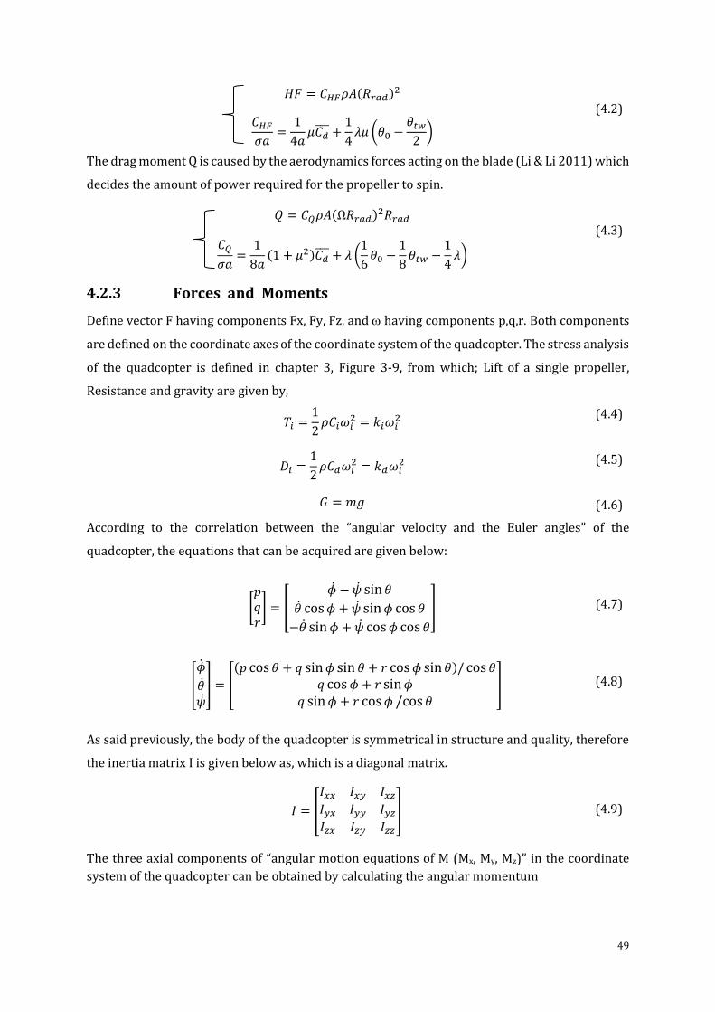
49
𝐻𝐹 = 𝐶𝐻𝐹𝜌𝐴(𝑅𝑟𝑎𝑑)2
𝐶𝐻𝐹
𝜎𝑎=
1
4𝑎𝜇𝐶𝑑 +
1
4𝜆𝜇 (𝜃0 −
𝜃𝑡𝑤
2)
(4.2)
The drag moment Q is caused by the aerodynamics forces acting on the blade (Li & Li 2011) which
decides the amount of power required for the propeller to spin.
𝑄 = 𝐶𝑄𝜌𝐴(Ω𝑅𝑟𝑎𝑑)2𝑅𝑟𝑎𝑑
𝐶𝑄
𝜎𝑎=
1
8𝑎(1 + 𝜇2)𝐶𝑑
+ 𝜆 (1
6𝜃0 −
1
8𝜃𝑡𝑤 −
1
4𝜆)
(4.3)
4.2.3 Forces and Moments
Define vector F having components Fx, Fy, Fz, and having components p,q,r. Both components
are defined on the coordinate axes of the coordinate system of the quadcopter. The stress analysis
of the quadcopter is defined in chapter 3, Figure 3-9, from which; Lift of a single propeller,
Resistance and gravity are given by,
𝑇𝑖 =
1
2𝜌𝐶𝑖𝜔𝑖
2 = 𝑘𝑖𝜔𝑖2
𝐷𝑖 =1
2𝜌𝐶𝑑𝜔𝑖
2 = 𝑘𝑑𝜔𝑖2
𝐺 = 𝑚𝑔
(4.4)
(4.5)
(4.6)
According to the correlation between the “angular velocity and the Euler angles” of the
quadcopter, the equations that can be acquired are given below:
[𝑝𝑞𝑟] = [
�� − �� sin𝜃
�� cos𝜙 + �� sin𝜙 cos𝜃
−�� sin𝜙 + �� cos𝜙 cos 𝜃
]
(4.7)
[
𝜙
����
] = [
(𝑝 cos𝜃 + 𝑞 sin𝜙 sin𝜃 + 𝑟 cos𝜙 sin𝜃)/ cos𝜃𝑞 cos𝜙 + 𝑟 sin𝜙
𝑞 sin𝜙 + 𝑟 cos𝜙 /cos 𝜃]
(4.8)
As said previously, the body of the quadcopter is symmetrical in structure and quality, therefore
the inertia matrix I is given below as, which is a diagonal matrix.
𝐼 = [
𝐼𝑥𝑥 𝐼𝑥𝑦 𝐼𝑥𝑧
𝐼𝑦𝑥 𝐼𝑦𝑦 𝐼𝑦𝑧
𝐼𝑧𝑥 𝐼𝑧𝑦 𝐼𝑧𝑧
]
(4.9)
The three axial components of “angular motion equations of M (Mx, My, Mz)” in the coordinate
system of the quadcopter can be obtained by calculating the angular momentum
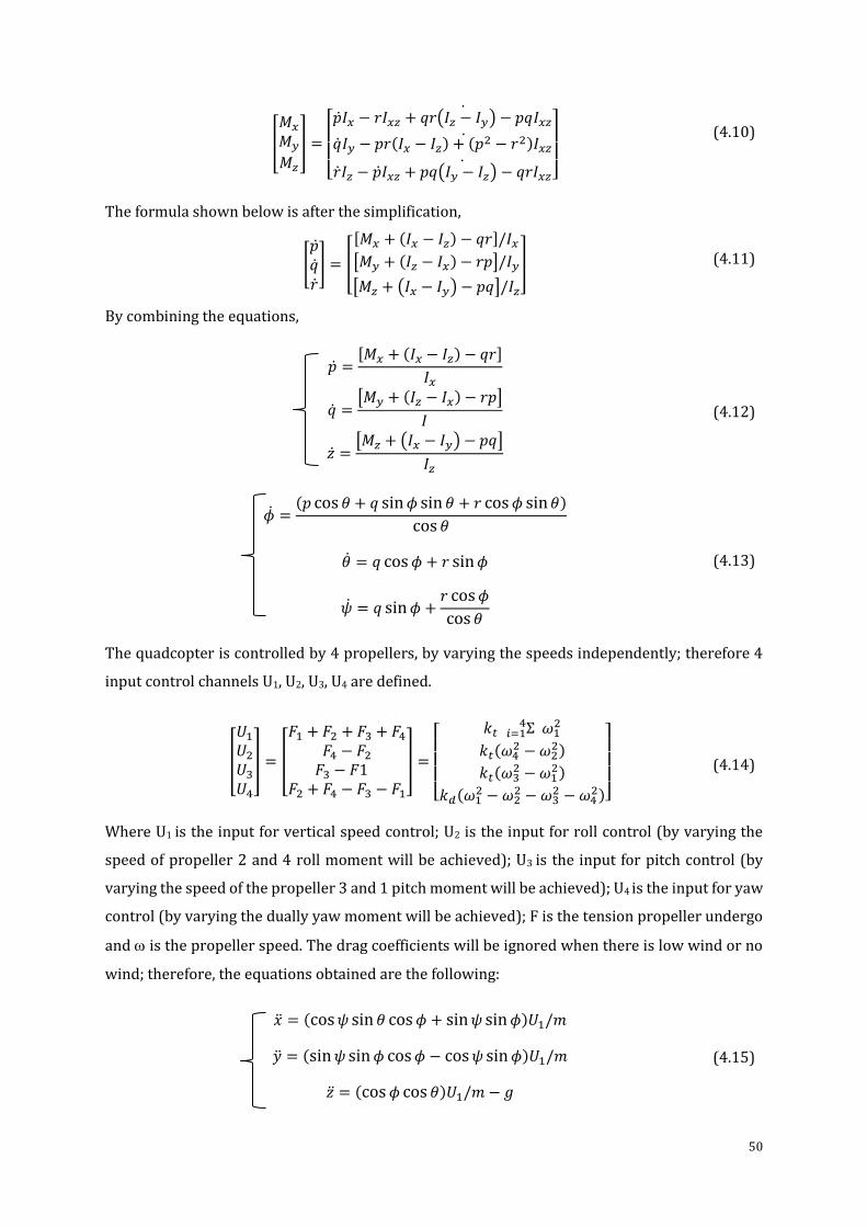
50
[
𝑀𝑥
𝑀𝑦
𝑀𝑧
] =
[ ��𝐼𝑥 − 𝑟𝐼𝑥𝑧 + 𝑞𝑟(𝐼𝑧 − 𝐼𝑦) − 𝑝𝑞𝐼𝑥𝑧
��𝐼𝑦 − 𝑝𝑟(𝐼𝑥 − 𝐼𝑧) + (𝑝2 − 𝑟2)𝐼𝑥𝑧
��𝐼𝑧 − ��𝐼𝑥𝑧 + 𝑝𝑞(𝐼𝑦 − 𝐼𝑧) − 𝑞𝑟𝐼𝑥𝑧
]
(4.10)
The formula shown below is after the simplification,
[������
] = [
[𝑀𝑥 + (𝐼𝑥 − 𝐼𝑧) − 𝑞𝑟]/𝐼𝑥[𝑀𝑦 + (𝐼𝑧 − 𝐼𝑥) − 𝑟𝑝]/𝐼𝑦
[𝑀𝑧 + (𝐼𝑥 − 𝐼𝑦) − 𝑝𝑞]/𝐼𝑧
]
(4.11)
By combining the equations,
�� =
[𝑀𝑥 + (𝐼𝑥 − 𝐼𝑧) − 𝑞𝑟]
𝐼𝑥
�� =[𝑀𝑦 + (𝐼𝑧 − 𝐼𝑥) − 𝑟𝑝]
𝐼
�� =[𝑀𝑧 + (𝐼𝑥 − 𝐼𝑦) − 𝑝𝑞]
𝐼𝑧
(4.12)
�� =
(𝑝 cos 𝜃 + 𝑞 sin𝜙 sin𝜃 + 𝑟 cos𝜙 sin𝜃)
cos 𝜃
�� = 𝑞 cos𝜙 + 𝑟 sin𝜙
�� = 𝑞 sin𝜙 +𝑟 cos𝜙
cos 𝜃
(4.13)
The quadcopter is controlled by 4 propellers, by varying the speeds independently; therefore 4
input control channels U1, U2, U3, U4 are defined.
[
𝑈1
𝑈2
𝑈3
𝑈4
] = [
𝐹1 + 𝐹2 + 𝐹3 + 𝐹4
𝐹4 − 𝐹2
𝐹3 − 𝐹1𝐹2 + 𝐹4 − 𝐹3 − 𝐹1
] =
[
𝑘𝑡 Σ 𝑖=14 𝜔1
2
𝑘𝑡(𝜔42 − 𝜔2
2)
𝑘𝑡(𝜔32 − 𝜔1
2)
𝑘𝑑(𝜔12 − 𝜔2
2 − 𝜔32 − 𝜔4
2)]
(4.14)
Where U1 is the input for vertical speed control; U2 is the input for roll control (by varying the
speed of propeller 2 and 4 roll moment will be achieved); U3 is the input for pitch control (by
varying the speed of the propeller 3 and 1 pitch moment will be achieved); U4 is the input for yaw
control (by varying the dually yaw moment will be achieved); F is the tension propeller undergo
and is the propeller speed. The drag coefficients will be ignored when there is low wind or no
wind; therefore, the equations obtained are the following:
�� = (cos𝜓 sin𝜃 cos𝜙 + sin𝜓 sin𝜙)𝑈1/𝑚
�� = (sin𝜓 sin𝜙 cos𝜙 − cos𝜓 sin𝜙)𝑈1/𝑚
�� = (cos𝜙 cos 𝜃)𝑈1/𝑚 − 𝑔
(4.15)
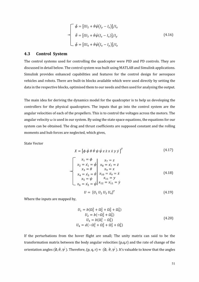
51
�� = [𝑙𝑈2 + ����(𝐼𝑦 − 𝐼𝑧)]/𝐼𝑥
�� = [𝑙𝑈3 + ����(𝐼𝑧 − 𝐼𝑥)]/𝐼𝑦
�� = [𝑙𝑈4 + ����(𝐼𝑥 − 𝐼𝑦)]/𝐼𝑧
(4.16)
4.3 Control System
The control systems used for controlling the quadcopter were PID and PD controls. They are
discussed in detail below. The control system was built using MATLAB and Simulink applications.
Simulink provides enhanced capabilities and features for the control design for aerospace
vehicles and robots. There are built-in blocks available which were used directly by setting the
data in the respective blocks, optimised them to our needs and then used for analysing the output.
The main idea for deriving the dynamics model for the quadcopter is to help us developing the
controllers for the physical quadcopters. The inputs that go into the control system are the
angular velocities of each of the propellers. This is to control the voltages across the motors. The
angular velocity 𝜔 is used in our system. By using the state space equations, the equations for our
system can be obtained. The drag and thrust coefficients are supposed constant and the rolling
moments and hub forces are neglected, which gives,
State Vector
𝑋 = [𝜙 �� 𝜃 𝜃 𝜓 𝜓 𝑧 𝑧 𝑥 �� 𝑦 𝑦 ]𝑇
(4.17)
𝑥1 = 𝜙
𝑥2 = 𝑥1 = ��𝑥3 = 𝜃
𝑥4 = 𝑥3 = ��𝑥5 = 𝜓
𝑥6 = 𝑥5 = ��
|
|
𝑥7 = 𝑧𝑥8 = 𝑥7 = ��
𝑥9 = 𝑥𝑥10 = 𝑥9 = ��
𝑥11 = 𝑦𝑥12 = 𝑥11 = ��
(4.18)
𝑈 = [𝑈1 𝑈2 𝑈3 𝑈4]𝑇 (4.19)
Where the inputs are mapped by,
𝑈1 = 𝑏(Ω12 + Ω2
2 + Ω32 + Ω4
2)
𝑈2 = 𝑏(−Ω22 + Ω4
2)
𝑈3 = 𝑏(Ω12 − Ω3
2)
𝑈4 = 𝑑(−Ω12 + Ω2
2 + Ω32 + Ω4
2)
(4.20)
If the perturbations from the hover flight are small; The unity matrix can said to be the
transformation matrix between the body angular velocities (p,q,r) and the rate of change of the
orientation angles (∅, ��, ) . Therefore, (p, q, r) ≈ (∅, ��, ) . It’s valuable to know that the angles
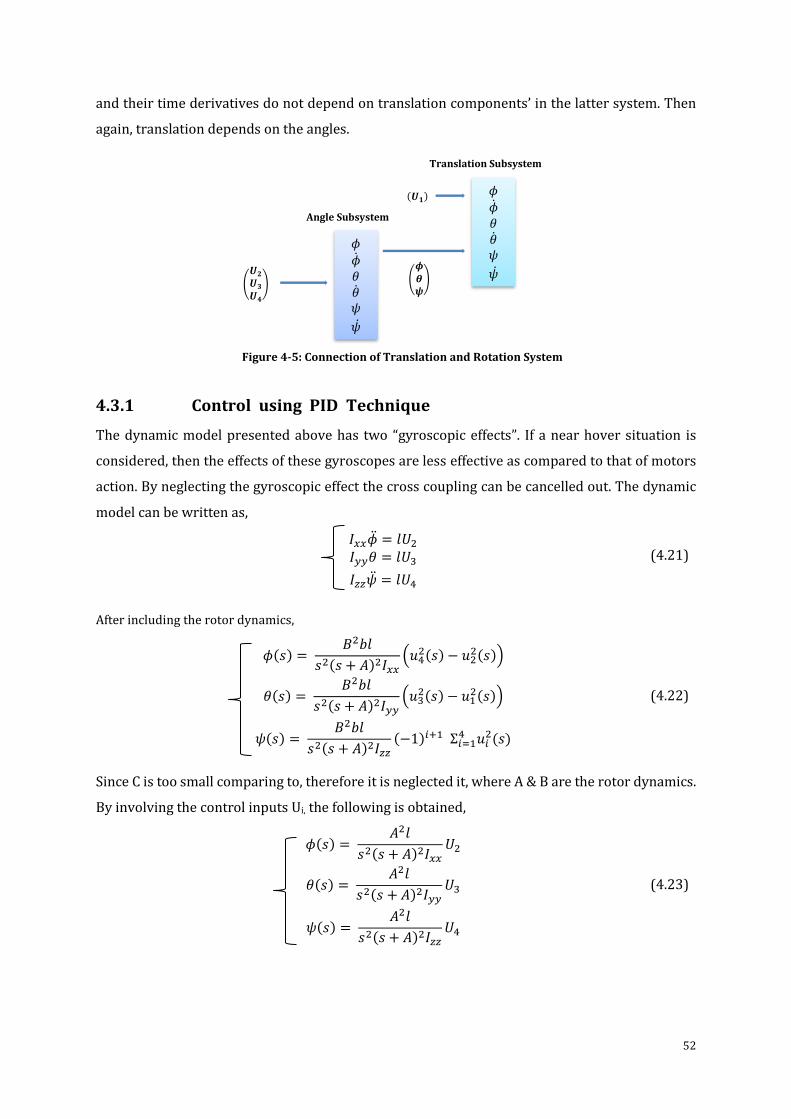
52
and their time derivatives do not depend on translation components’ in the latter system. Then
again, translation depends on the angles.
4.3.1 Control using PID Technique
The dynamic model presented above has two “gyroscopic effects”. If a near hover situation is
considered, then the effects of these gyroscopes are less effective as compared to that of motors
action. By neglecting the gyroscopic effect the cross coupling can be cancelled out. The dynamic
model can be written as,
𝐼𝑥𝑥�� = 𝑙𝑈2
𝐼𝑦𝑦𝜃 = 𝑙𝑈3
𝐼𝑧𝑧�� = 𝑙𝑈4
(4.21)
After including the rotor dynamics,
𝜙(𝑠) =
𝐵2𝑏𝑙
𝑠2(𝑠 + 𝐴)2𝐼𝑥𝑥(𝑢4
2(𝑠) − 𝑢22(𝑠))
𝜃(𝑠) = 𝐵2𝑏𝑙
𝑠2(𝑠 + 𝐴)2𝐼𝑦𝑦(𝑢3
2(𝑠) − 𝑢12(𝑠))
𝜓(𝑠) = 𝐵2𝑏𝑙
𝑠2(𝑠 + 𝐴)2𝐼𝑧𝑧(−1)𝑖+1 Σ𝑖=1
4 𝑢𝑖2(𝑠)
(4.22)
Since C is too small comparing to, therefore it is neglected it, where A & B are the rotor dynamics.
By involving the control inputs Ui, the following is obtained,
𝜙(𝑠) =
𝐴2𝑙
𝑠2(𝑠 + 𝐴)2𝐼𝑥𝑥𝑈2
𝜃(𝑠) = 𝐴2𝑙
𝑠2(𝑠 + 𝐴)2𝐼𝑦𝑦𝑈3
𝜓(𝑠) = 𝐴2𝑙
𝑠2(𝑠 + 𝐴)2𝐼𝑧𝑧𝑈4
(4.23)
൭𝝓𝜽𝝍
൱
Angle Subsystem
Translation Subsystem
൭𝑼𝟐
𝑼𝟑
𝑼𝟒
൱
(𝑼𝟏)
𝜙
𝜙𝜃𝜃𝜓
��
𝜙
𝜙𝜃𝜃𝜓
��
Figure 4-5: Connection of Translation and Rotation System
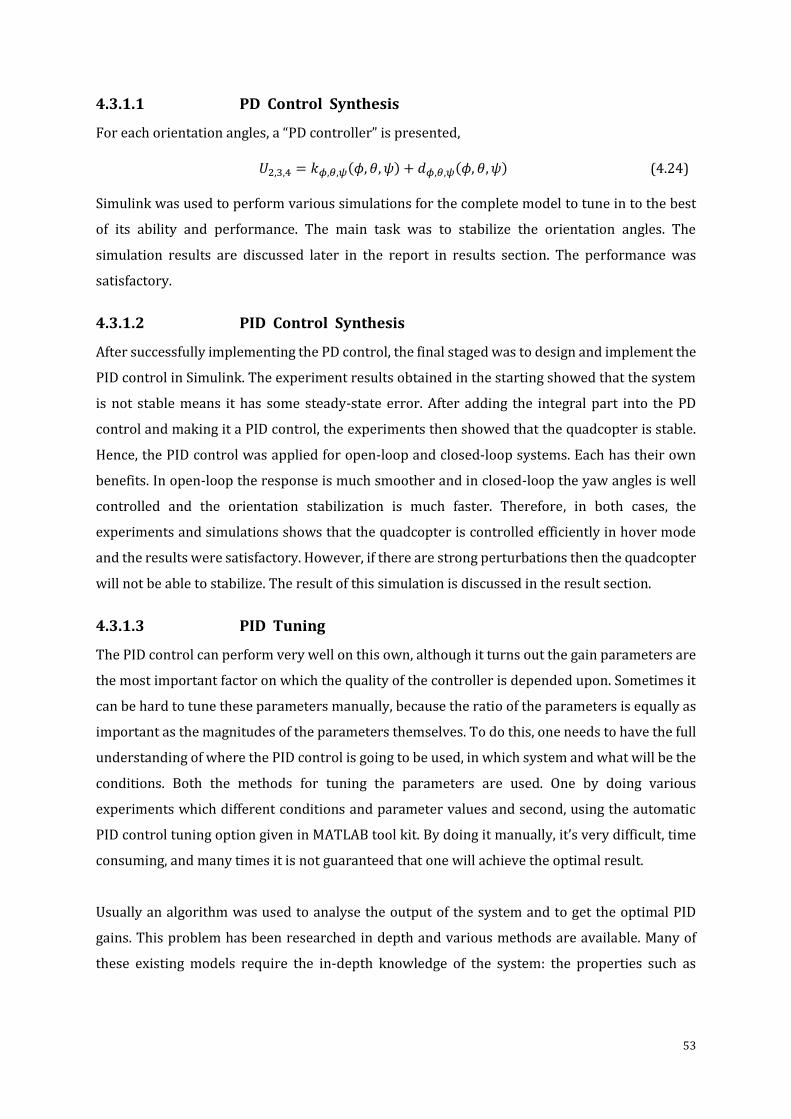
53
4.3.1.1 PD Control Synthesis
For each orientation angles, a “PD controller” is presented,
𝑈2,3,4 = 𝑘𝜙,𝜃,𝜓(𝜙, 𝜃, 𝜓) + 𝑑𝜙,𝜃,𝜓(𝜙, 𝜃, 𝜓) (4.24)
Simulink was used to perform various simulations for the complete model to tune in to the best
of its ability and performance. The main task was to stabilize the orientation angles. The
simulation results are discussed later in the report in results section. The performance was
satisfactory.
4.3.1.2 PID Control Synthesis
After successfully implementing the PD control, the final staged was to design and implement the
PID control in Simulink. The experiment results obtained in the starting showed that the system
is not stable means it has some steady-state error. After adding the integral part into the PD
control and making it a PID control, the experiments then showed that the quadcopter is stable.
Hence, the PID control was applied for open-loop and closed-loop systems. Each has their own
benefits. In open-loop the response is much smoother and in closed-loop the yaw angles is well
controlled and the orientation stabilization is much faster. Therefore, in both cases, the
experiments and simulations shows that the quadcopter is controlled efficiently in hover mode
and the results were satisfactory. However, if there are strong perturbations then the quadcopter
will not be able to stabilize. The result of this simulation is discussed in the result section.
4.3.1.3 PID Tuning
The PID control can perform very well on this own, although it turns out the gain parameters are
the most important factor on which the quality of the controller is depended upon. Sometimes it
can be hard to tune these parameters manually, because the ratio of the parameters is equally as
important as the magnitudes of the parameters themselves. To do this, one needs to have the full
understanding of where the PID control is going to be used, in which system and what will be the
conditions. Both the methods for tuning the parameters are used. One by doing various
experiments which different conditions and parameter values and second, using the automatic
PID control tuning option given in MATLAB tool kit. By doing it manually, it’s very difficult, time
consuming, and many times it is not guaranteed that one will achieve the optimal result.
Usually an algorithm was used to analyse the output of the system and to get the optimal PID
gains. This problem has been researched in depth and various methods are available. Many of
these existing models require the in-depth knowledge of the system: the properties such as
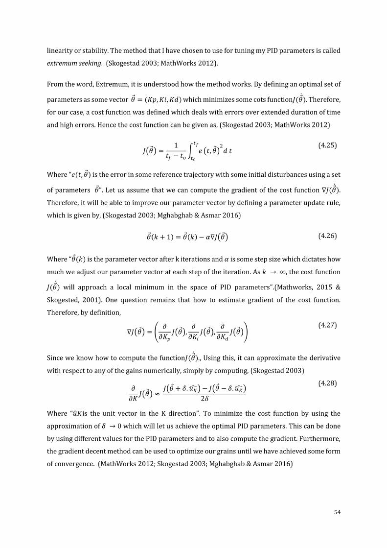
54
linearity or stability. The method that I have chosen to use for tuning my PID parameters is called
extremum seeking. (Skogestad 2003; MathWorks 2012).
From the word, Extremum, it is understood how the method works. By defining an optimal set of
parameters as some vector 𝜃 = (𝐾𝑝, 𝐾𝑖, 𝐾𝑑) which minimizes some cots function𝐽(𝜃). Therefore,
for our case, a cost function was defined which deals with errors over extended duration of time
and high errors. Hence the cost function can be given as, (Skogestad 2003; MathWorks 2012)
𝐽(𝜃) =
1
𝑡𝑓 − 𝑡𝑜∫ 𝑒
𝑡𝑓
𝑡0
(𝑡, 𝜃)2𝑑 𝑡
(4.25)
Where “𝑒(𝑡, 𝜃) is the error in some reference trajectory with some initial disturbances using a set
of parameters 𝜃”. Let us assume that we can compute the gradient of the cost function ∇𝐽(𝜃).
Therefore, it will be able to improve our parameter vector by defining a parameter update rule,
which is given by, (Skogestad 2003; Mghabghab & Asmar 2016)
𝜃(𝑘 + 1) = 𝜃(𝑘) − 𝛼∇𝐽(𝜃) (4.26)
Where “𝜃(𝑘) is the parameter vector after k iterations and 𝛼 is some step size which dictates how
much we adjust our parameter vector at each step of the iteration. As 𝑘 → ∞, the cost function
𝐽(𝜃) will approach a local minimum in the space of PID parameters”.(Mathworks, 2015 &
Skogested, 2001). One question remains that how to estimate gradient of the cost function.
Therefore, by definition,
∇𝐽(𝜃) = ൭
𝜕
𝜕𝐾𝑝𝐽(𝜃),
𝜕
𝜕𝐾𝑖𝐽(𝜃),
𝜕
𝜕𝐾𝑑𝐽(𝜃)൱
(4.27)
Since we know how to compute the function𝐽(𝜃)., Using this, it can approximate the derivative
with respect to any of the gains numerically, simply by computing, (Skogestad 2003)
𝜕
𝜕𝐾𝐽(𝜃) ≈
𝐽(𝜃 + 𝛿. 𝑢��) − 𝐽(𝜃 − 𝛿. 𝑢��)
2𝛿
(4.28)
Where “��𝐾is the unit vector in the K direction”. To minimize the cost function by using the
approximation of 𝛿 → 0 which will let us achieve the optimal PID parameters. This can be done
by using different values for the PID parameters and to also compute the gradient. Furthermore,
the gradient decent method can be used to optimize our grains until we have achieved some form
of convergence. (MathWorks 2012; Skogestad 2003; Mghabghab & Asmar 2016)
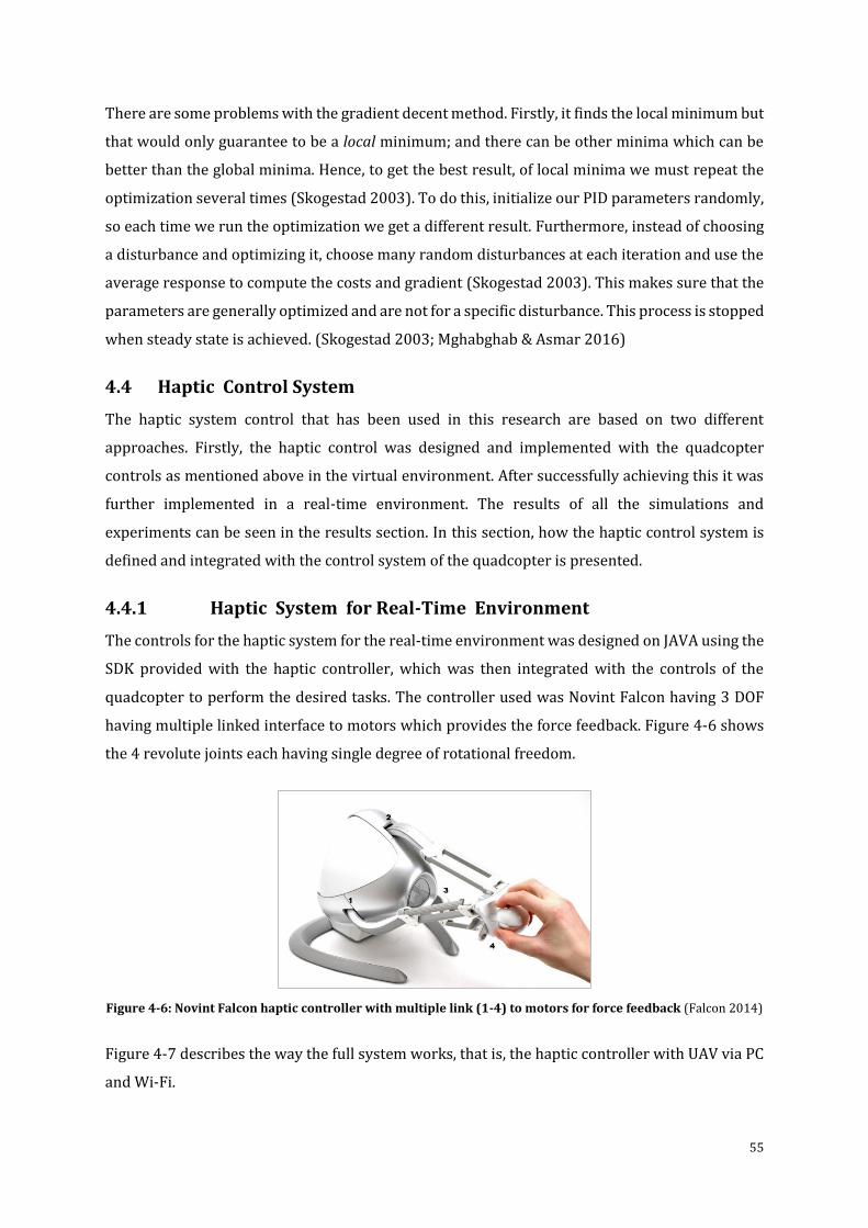
55
There are some problems with the gradient decent method. Firstly, it finds the local minimum but
that would only guarantee to be a local minimum; and there can be other minima which can be
better than the global minima. Hence, to get the best result, of local minima we must repeat the
optimization several times (Skogestad 2003). To do this, initialize our PID parameters randomly,
so each time we run the optimization we get a different result. Furthermore, instead of choosing
a disturbance and optimizing it, choose many random disturbances at each iteration and use the
average response to compute the costs and gradient (Skogestad 2003). This makes sure that the
parameters are generally optimized and are not for a specific disturbance. This process is stopped
when steady state is achieved. (Skogestad 2003; Mghabghab & Asmar 2016)
4.4 Haptic Control System
The haptic system control that has been used in this research are based on two different
approaches. Firstly, the haptic control was designed and implemented with the quadcopter
controls as mentioned above in the virtual environment. After successfully achieving this it was
further implemented in a real-time environment. The results of all the simulations and
experiments can be seen in the results section. In this section, how the haptic control system is
defined and integrated with the control system of the quadcopter is presented.
4.4.1 Haptic System for Real-Time Environment
The controls for the haptic system for the real-time environment was designed on JAVA using the
SDK provided with the haptic controller, which was then integrated with the controls of the
quadcopter to perform the desired tasks. The controller used was Novint Falcon having 3 DOF
having multiple linked interface to motors which provides the force feedback. Figure 4-6 shows
the 4 revolute joints each having single degree of rotational freedom.
Figure 4-6: Novint Falcon haptic controller with multiple link (1-4) to motors for force feedback (Falcon 2014)
Figure 4-7 describes the way the full system works, that is, the haptic controller with UAV via PC
and Wi-Fi.
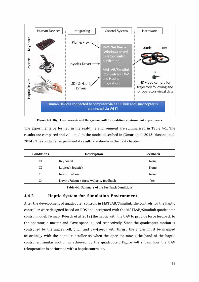
56
Figure 4-7: High Level overview of the system built for real-time environment experiments
The experiments performed in the real-time environment are summarised in Table 4-1. The
results are compared and validated to the model described in (Omari et al. 2013; Masone et al.
2014). The conducted experimental results are shown in the next chapter.
Conditions Description Feedback
C1 Keyboard None
C2 Logitech Joystick None
C3 Novint Falcon None
C4 Novint Falcon + force/velocity feedback Yes
Table 4-1: Summary of the Feedback Conditions
4.4.2 Haptic System for Simulation Environment
After the development of quadcopter controls in MATLAB/Simulink, the controls for the haptic
controller were designed based on ROS and integrated with the MATLAB/Simulink quadcopter
control model. To map (Rüesch et al. 2012) the haptic with the UAV to provide force feedback to
the operator, a master and slave space is used respectively. Since the quadcopter motion is
controlled by the angles roll, pitch and yaw(zero) with thrust, the angles must be mapped
accordingly with the haptic controller so when the operator moves the hand of the haptic
controller, similar motion is achieved by the quadcopter. Figure 4-8 shows how the UAV
teleoperation is performed with a haptic controller.
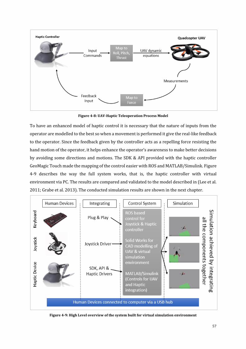
57
Figure 4-8: UAV-Haptic Teleoperation Process Model
To have an enhanced model of haptic control it is necessary that the nature of inputs from the
operator are modelled to the best so when a movement is performed it give the real-like feedback
to the operator. Since the feedback given by the controller acts as a repelling force resisting the
hand motion of the operator, it helps enhance the operator’s awareness to make better decisions
by avoiding some directions and motions. The SDK & API provided with the haptic controller
GeoMagic Touch made the mapping of the control easier with ROS and MATLAB/Simulink. Figure
4-9 describes the way the full system works, that is, the haptic controller with virtual
environment via PC. The results are compared and validated to the model described in (Lee et al.
2011; Grabe et al. 2013). The conducted simulation results are shown in the next chapter.
Figure 4-9: High Level overview of the system built for virtual simulation environment
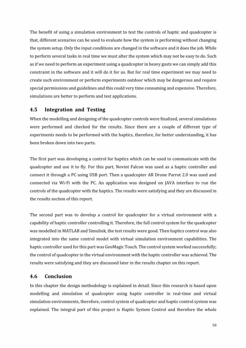
58
The benefit of using a simulation environment to test the controls of haptic and quadcopter is
that, different scenarios can be used to evaluate how the system is performing without changing
the system setup. Only the input conditions are changed in the software and it does the job. While
to perform several tasks in real time we must alter the system which may not be easy to do. Such
as if we need to perform an experiment using a quadcopter in heavy gusts we can simply add this
constraint in the software and it will do it for us. But for real time experiment we may need to
create such environment or perform experiments outdoor which may be dangerous and require
special permissions and guidelines and this could very time consuming and expensive. Therefore,
simulations are better to perform and test applications.
4.5 Integration and Testing
When the modelling and designing of the quadcopter controls were finalized, several simulations
were performed and checked for the results. Since there are a couple of different type of
experiments needs to be performed with the haptics, therefore, for better understanding, it has
been broken down into two parts.
The first part was developing a control for haptics which can be used to communicate with the
quadcopter and use it to fly. For this part, Novint Falcon was used as a haptic controller and
connect it through a PC using USB port. Then a quadcopter AR Drone Parrot 2.0 was used and
connected via Wi-Fi with the PC. An application was designed on JAVA interface to run the
controls of the quadcopter with the haptics. The results were satisfying and they are discussed in
the results section of this report.
The second part was to develop a control for quadcopter for a virtual environment with a
capability of haptic controller controlling it. Therefore, the full control system for the quadcopter
was modelled in MATLAB and Simulink, the test results were good. Then haptics control was also
integrated into the same control model with virtual simulation environment capabilities. The
haptic controller used for this part was GeoMagic Touch. The control system worked successfully;
the control of quadcopter in the virtual environment with the haptic controller was achieved. The
results were satisfying and they are discussed later in the results chapter on this report.
4.6 Conclusion
In this chapter the design methodology is explained in detail. Since this research is based upon
modelling and simulation of quadcopter using haptic controller in real-time and virtual
simulation environments, therefore, control system of quadcopter and haptic control system was
explained. The integral part of this project is Haptic System Control and therefore the whole
59
concept is built around it and is explained throughout this report. Furthermore, the integration
and testing is also defined in this section to show how the system communicates with all the
components for the real-time and virtual simulation environment experiments. In the next
chapter the results of the experiments are discussed in detail which satisfies the requirements of
this research and confirms the concept of haptic control for UAV is a novel idea.
60
Results and Discussion
“ T he most exciting phrase to hear in science, the one that
heralds new discoveries, is not ‘Eureka!’ (I found it!) but
‘That’s funny’ ”
[Isaac Asimov]
“In chapter 3, research methodology was described for the design and development of the system.
It covered from designing of quadcopter to hardware selection and electronics to software
selection. Chapter 4 introduced the design methodology with the design concept and mechanical
and system properties with haptic controls, as well as system testing and integration.” The aim of
this chapter is to discuss the designing results and the results obtained from the experiments and
simulations done for specific methods as explained in previous chapters.
5.1 Final Model & Control of Quadcopter
To test and evaluate the model, a few designs were considered and after detailed research and
consultancy with the experts the model that was chosen is discussed below. The modelling
process start form the very basic model where just some basic concepts were used to model the
control of the quadcopter. After getting successful results the model was enhanced to a more
sophisticated model having real like features. Furthermore, the features of the quadcopter model
and control can still be improved to a certain extent for a system or application. The basic model
of quadcopter model with PD control is discussed below:
A classical PD control concept was applied to obtain the desired results. The control of the vertical
position can be obtained by using the following control input (Patel et al. 2012)
𝑢1 =
𝑟1 + 𝑚𝑔
cos𝜃 cos𝜑
(5.1)
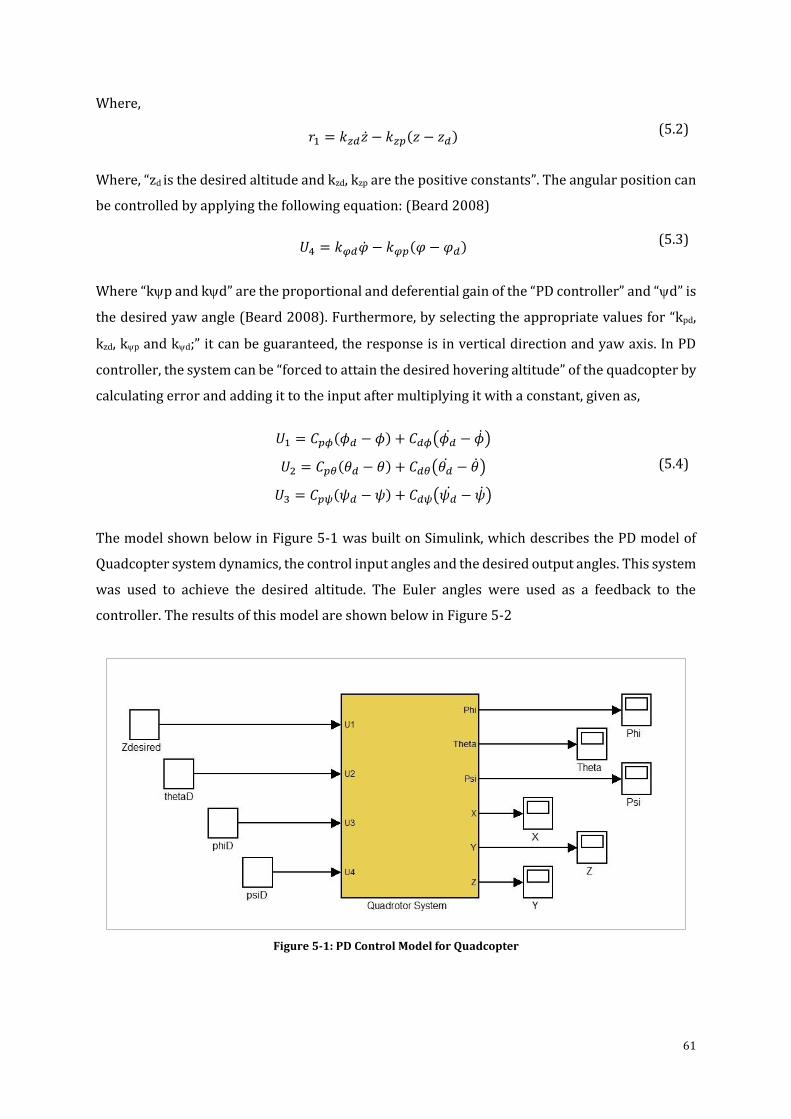
61
Where,
𝑟1 = 𝑘𝑧𝑑�� − 𝑘𝑧𝑝(𝑧 − 𝑧𝑑)
(5.2)
Where, “zd is the desired altitude and kzd, kzp are the positive constants”. The angular position can
be controlled by applying the following equation: (Beard 2008)
𝑈4 = 𝑘𝜑𝑑�� − 𝑘𝜑𝑝(𝜑 − 𝜑𝑑)
(5.3)
Where “kp and kd” are the proportional and deferential gain of the “PD controller” and “d” is
the desired yaw angle (Beard 2008). Furthermore, by selecting the appropriate values for “kpd,
kzd, kp and kd;” it can be guaranteed, the response is in vertical direction and yaw axis. In PD
controller, the system can be “forced to attain the desired hovering altitude” of the quadcopter by
calculating error and adding it to the input after multiplying it with a constant, given as,
𝑈1 = 𝐶𝑝𝜙(𝜙𝑑 − 𝜙) + 𝐶𝑑𝜙(𝜙�� − ��)
𝑈2 = 𝐶𝑝𝜃(𝜃𝑑 − 𝜃) + 𝐶𝑑𝜃(𝜃�� − ��)
𝑈3 = 𝐶𝑝𝜓(𝜓𝑑 − 𝜓) + 𝐶𝑑𝜓(𝜓�� − ��)
(5.4)
The model shown below in Figure 5-1 was built on Simulink, which describes the PD model of
Quadcopter system dynamics, the control input angles and the desired output angles. This system
was used to achieve the desired altitude. The Euler angles were used as a feedback to the
controller. The results of this model are shown below in Figure 5-2
Figure 5-1: PD Control Model for Quadcopter
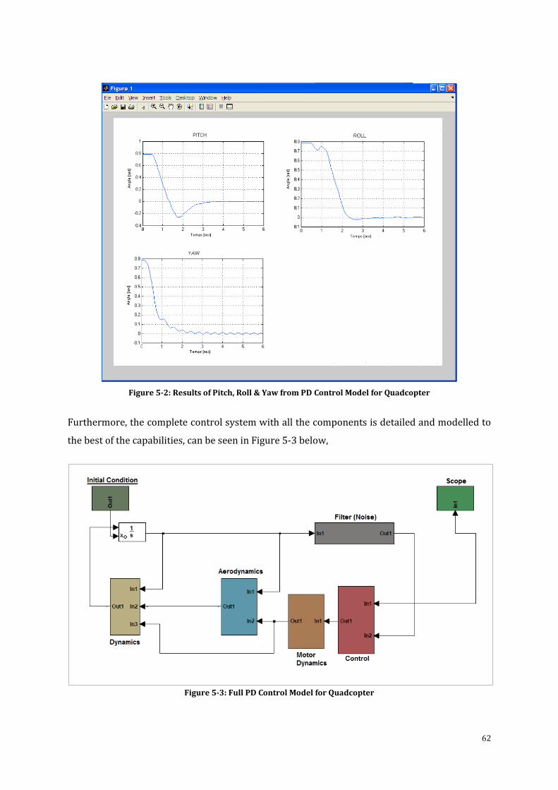
62
Figure 5-2: Results of Pitch, Roll & Yaw from PD Control Model for Quadcopter
Furthermore, the complete control system with all the components is detailed and modelled to
the best of the capabilities, can be seen in Figure 5-3 below,
Figure 5-3: Full PD Control Model for Quadcopter
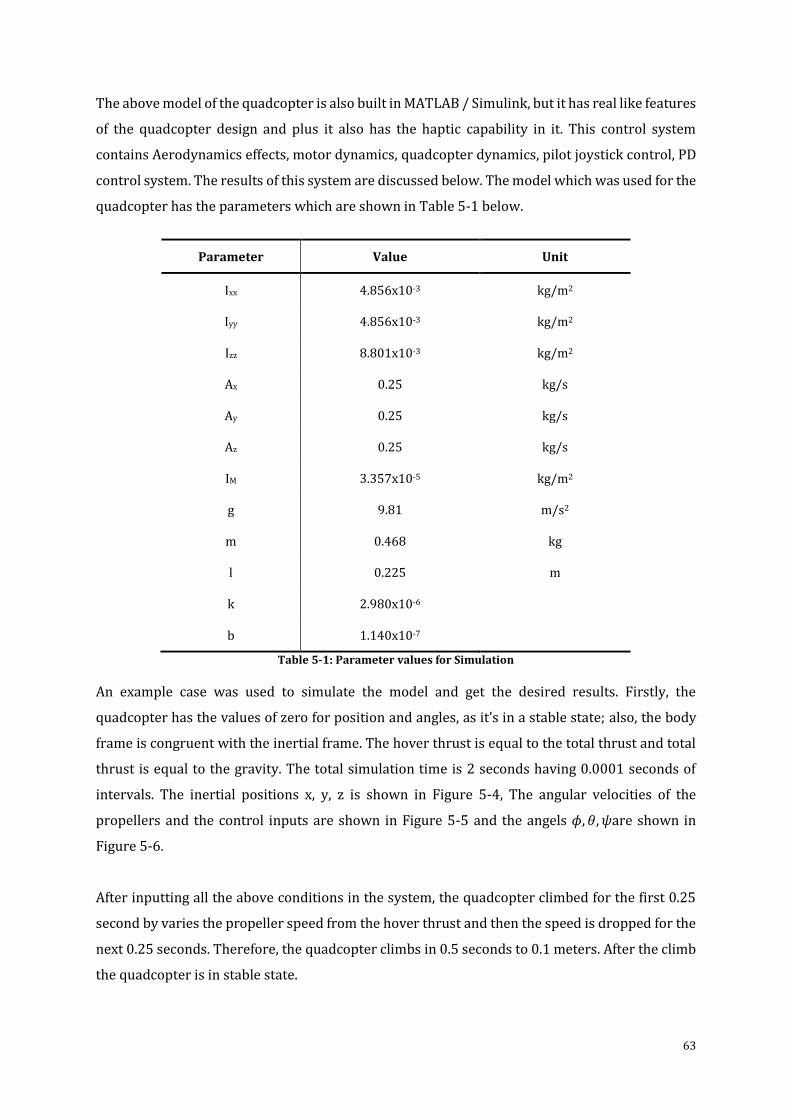
63
The above model of the quadcopter is also built in MATLAB / Simulink, but it has real like features
of the quadcopter design and plus it also has the haptic capability in it. This control system
contains Aerodynamics effects, motor dynamics, quadcopter dynamics, pilot joystick control, PD
control system. The results of this system are discussed below. The model which was used for the
quadcopter has the parameters which are shown in Table 5-1 below.
Parameter Value Unit
Ixx 4.856x10⁻³ kg/m2
Iyy 4.856x10⁻³ kg/m2
Izz 8.801x10⁻³ kg/m2
Ax 0.25 kg/s
Ay 0.25 kg/s
Az 0.25 kg/s
IM 3.357x10⁻⁵ kg/m2
g 9.81 m/s2
m 0.468 kg
l 0.225 m
k 2.980x10⁻⁶
b 1.140x10⁻⁷
Table 5-1: Parameter values for Simulation
An example case was used to simulate the model and get the desired results. Firstly, the
quadcopter has the values of zero for position and angles, as it’s in a stable state; also, the body
frame is congruent with the inertial frame. The hover thrust is equal to the total thrust and total
thrust is equal to the gravity. The total simulation time is 2 seconds having 0.0001 seconds of
intervals. The inertial positions x, y, z is shown in Figure 5-4, The angular velocities of the
propellers and the control inputs are shown in Figure 5-5 and the angels 𝜙, 𝜃, 𝜓are shown in
Figure 5-6.
After inputting all the above conditions in the system, the quadcopter climbed for the first 0.25
second by varies the propeller speed from the hover thrust and then the speed is dropped for the
next 0.25 seconds. Therefore, the quadcopter climbs in 0.5 seconds to 0.1 meters. After the climb
the quadcopter is in stable state.
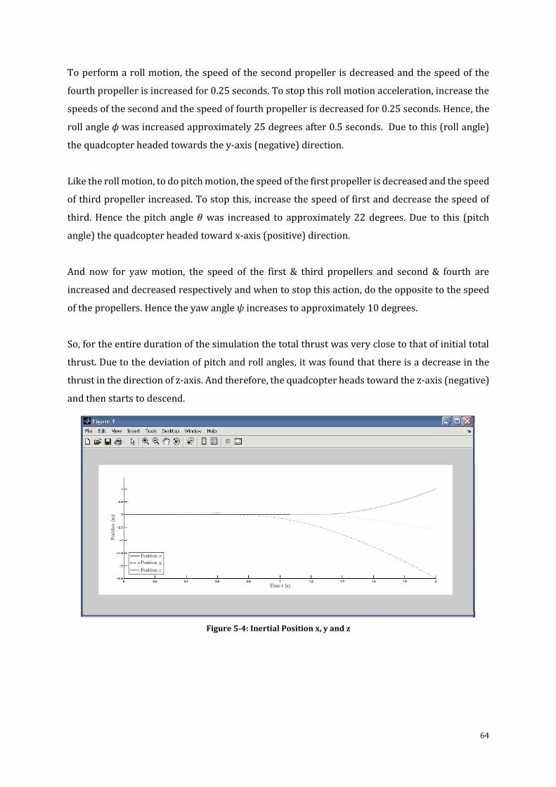
64
To perform a roll motion, the speed of the second propeller is decreased and the speed of the
fourth propeller is increased for 0.25 seconds. To stop this roll motion acceleration, increase the
speeds of the second and the speed of fourth propeller is decreased for 0.25 seconds. Hence, the
roll angle 𝜙 was increased approximately 25 degrees after 0.5 seconds. Due to this (roll angle)
the quadcopter headed towards the y-axis (negative) direction.
Like the roll motion, to do pitch motion, the speed of the first propeller is decreased and the speed
of third propeller increased. To stop this, increase the speed of first and decrease the speed of
third. Hence the pitch angle 𝜃 was increased to approximately 22 degrees. Due to this (pitch
angle) the quadcopter headed toward x-axis (positive) direction.
And now for yaw motion, the speed of the first & third propellers and second & fourth are
increased and decreased respectively and when to stop this action, do the opposite to the speed
of the propellers. Hence the yaw angle 𝜓 increases to approximately 10 degrees.
So, for the entire duration of the simulation the total thrust was very close to that of initial total
thrust. Due to the deviation of pitch and roll angles, it was found that there is a decrease in the
thrust in the direction of z-axis. And therefore, the quadcopter heads toward the z-axis (negative)
and then starts to descend.
Figure 5-4: Inertial Position x, y and z
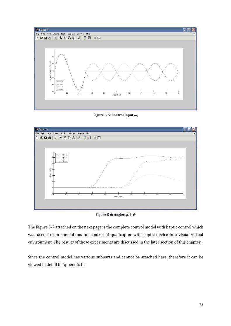
65
Figure 5-5: Control Input 𝝎𝒊
Figure 5-6: Angles 𝝓.𝜽,𝝍
The Figure 5-7 attached on the next page is the complete control model with haptic control which
was used to run simulations for control of quadcopter with haptic device in a visual virtual
environment. The results of these experiments are discussed in the later section of this chapter.
Since the control model has various subparts and cannot be attached here, therefore it can be
viewed in detail in Appendix II.
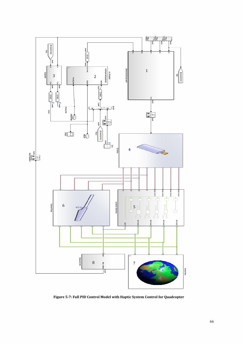
66
Figure 5-7: Full PID Control Model with Haptic System Control for Quadcopter
1
2 3
4
5 6
7 8
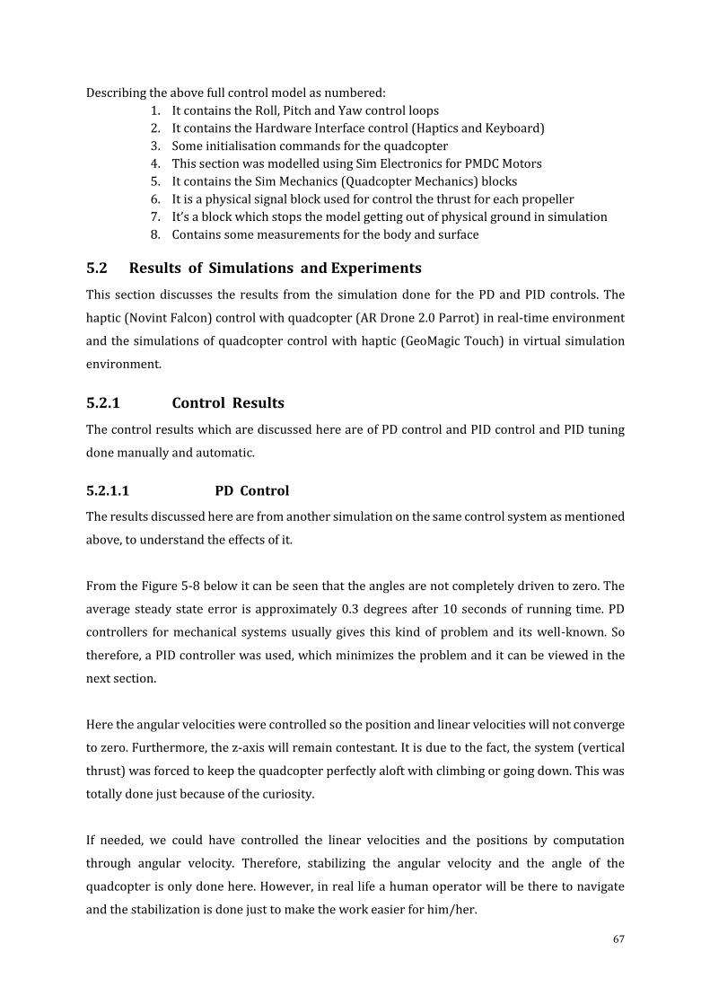
67
Describing the above full control model as numbered:
1. It contains the Roll, Pitch and Yaw control loops
2. It contains the Hardware Interface control (Haptics and Keyboard)
3. Some initialisation commands for the quadcopter
4. This section was modelled using Sim Electronics for PMDC Motors
5. It contains the Sim Mechanics (Quadcopter Mechanics) blocks
6. It is a physical signal block used for control the thrust for each propeller
7. It’s a block which stops the model getting out of physical ground in simulation
8. Contains some measurements for the body and surface
5.2 Results of Simulations and Experiments
This section discusses the results from the simulation done for the PD and PID controls. The
haptic (Novint Falcon) control with quadcopter (AR Drone 2.0 Parrot) in real-time environment
and the simulations of quadcopter control with haptic (GeoMagic Touch) in virtual simulation
environment.
5.2.1 Control Results
The control results which are discussed here are of PD control and PID control and PID tuning
done manually and automatic.
5.2.1.1 PD Control
The results discussed here are from another simulation on the same control system as mentioned
above, to understand the effects of it.
From the Figure 5-8 below it can be seen that the angles are not completely driven to zero. The
average steady state error is approximately 0.3 degrees after 10 seconds of running time. PD
controllers for mechanical systems usually gives this kind of problem and its well-known. So
therefore, a PID controller was used, which minimizes the problem and it can be viewed in the
next section.
Here the angular velocities were controlled so the position and linear velocities will not converge
to zero. Furthermore, the z-axis will remain contestant. It is due to the fact, the system (vertical
thrust) was forced to keep the quadcopter perfectly aloft with climbing or going down. This was
totally done just because of the curiosity.
If needed, we could have controlled the linear velocities and the positions by computation
through angular velocity. Therefore, stabilizing the angular velocity and the angle of the
quadcopter is only done here. However, in real life a human operator will be there to navigate
and the stabilization is done just to make the work easier for him/her.
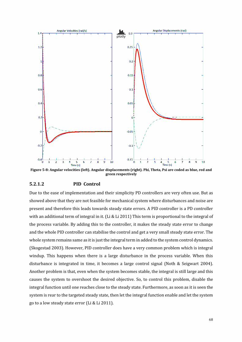
68
Figure 5-8: Angular velocities (left). Angular displacements (right). Phi, Theta, Psi are coded as blue, red and
green respectively
5.2.1.2 PID Control
Due to the ease of implementation and their simplicity PD controllers are very often use. But as
showed above that they are not feasible for mechanical system where disturbances and noise are
present and therefore this leads towards steady state errors. A PID controller is a PD controller
with an additional term of integral in it. (Li & Li 2011) This term is proportional to the integral of
the process variable. By adding this to the controller, it makes the steady state error to change
and the whole PID controller can stabilise the control and get a very small steady state error. The
whole system remains same as it is just the integral term in added to the system control dynamics.
(Skogestad 2003). However, PID controller does have a very common problem which is integral
windup. This happens when there is a large disturbance in the process variable. When this
disturbance is integrated in time, it becomes a large control signal (Noth & Seigwart 2004).
Another problem is that, even when the system becomes stable, the integral is still large and this
causes the system to overshoot the desired objective. So, to control this problem, disable the
integral function until one reaches close to the steady state. Furthermore, as soon as it is seen the
system is rear to the targeted steady state, then let the integral function enable and let the system
go to a low steady state error (Li & Li 2011).
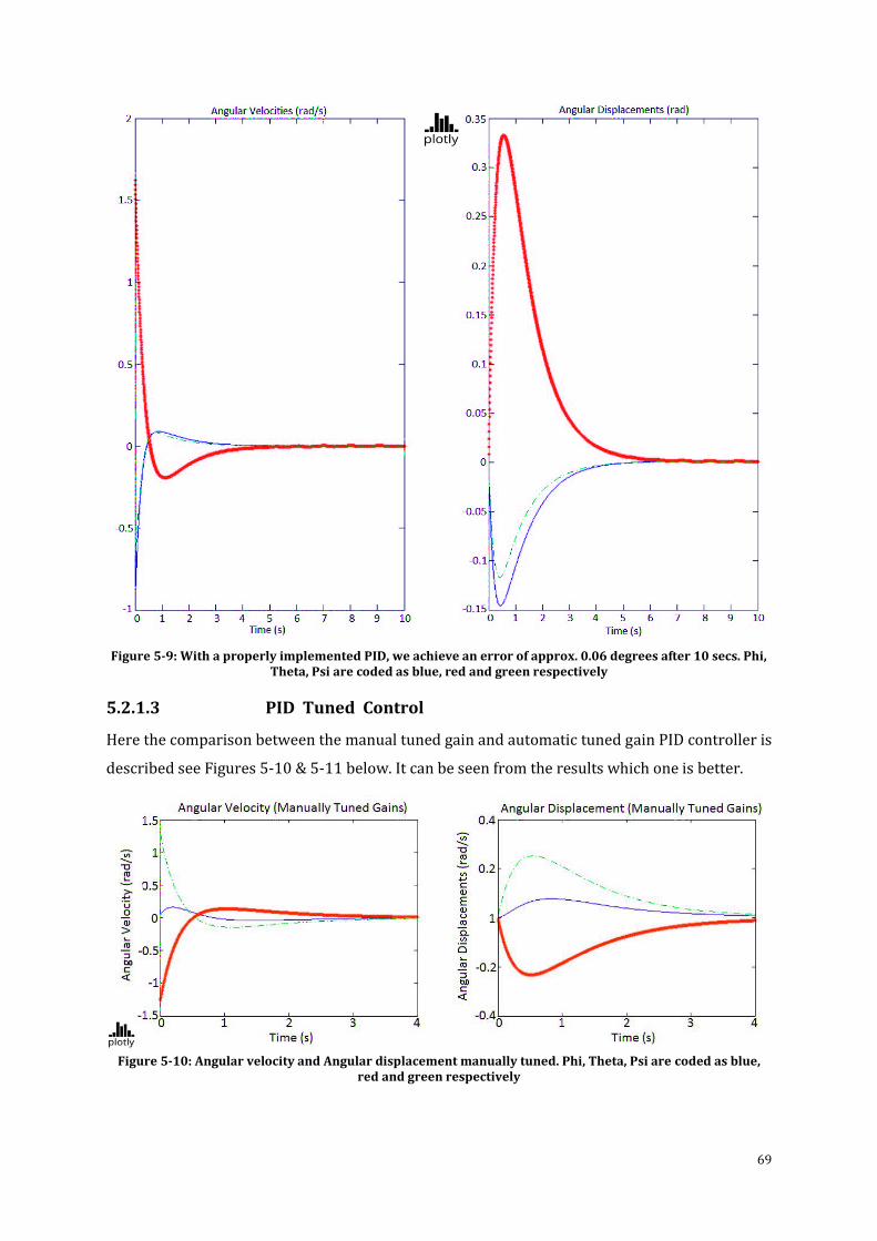
69
Figure 5-9: With a properly implemented PID, we achieve an error of approx. 0.06 degrees after 10 secs. Phi, Theta, Psi are coded as blue, red and green respectively
5.2.1.3 PID Tuned Control
Here the comparison between the manual tuned gain and automatic tuned gain PID controller is
described see Figures 5-10 & 5-11 below. It can be seen from the results which one is better.
Figure 5-10: Angular velocity and Angular displacement manually tuned. Phi, Theta, Psi are coded as blue,
red and green respectively
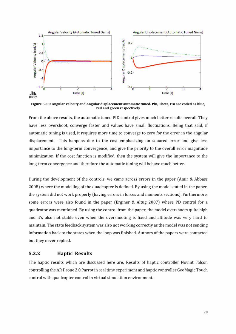
70
Figure 5-11: Angular velocity and Angular displacement automatic tuned. Phi, Theta, Psi are coded as blue, red and green respectively
From the above results, the automatic tuned PID control gives much better results overall. They
have less overshoot, converge faster and values have small fluctuations. Being that said, if
automatic tuning is used, it requires more time to converge to zero for the error in the angular
displacement. This happens due to the cost emphasizing on squared error and give less
importance to the long-term convergence; and give the priority to the overall error magnitude
minimization. If the cost function is modified, then the system will give the importance to the
long-term convergence and therefore the automatic tuning will behave much better.
During the development of the controls, we came across errors in the paper (Amir & Abbass
2008) where the modelling of the quadcopter is defined. By using the model stated in the paper,
the system did not work properly (having errors in forces and moments sections). Furthermore,
some errors were also found in the paper (Erginer & Altug 2007) where PD control for a
quadrotor was mentioned. By using the control from the paper, the model overshoots quite high
and it’s also not stable even when the overshooting is fixed and altitude was very hard to
maintain. The state feedback system was also not working correctly as the model was not sending
information back to the states when the loop was finished. Authors of the papers were contacted
but they never replied.
5.2.2 Haptic Results
The haptic results which are discussed here are; Results of haptic controller Novint Falcon
controlling the AR Drone 2.0 Parrot in real time experiment and haptic controller GeoMagic Touch
control with quadcopter control in virtual simulation environment.
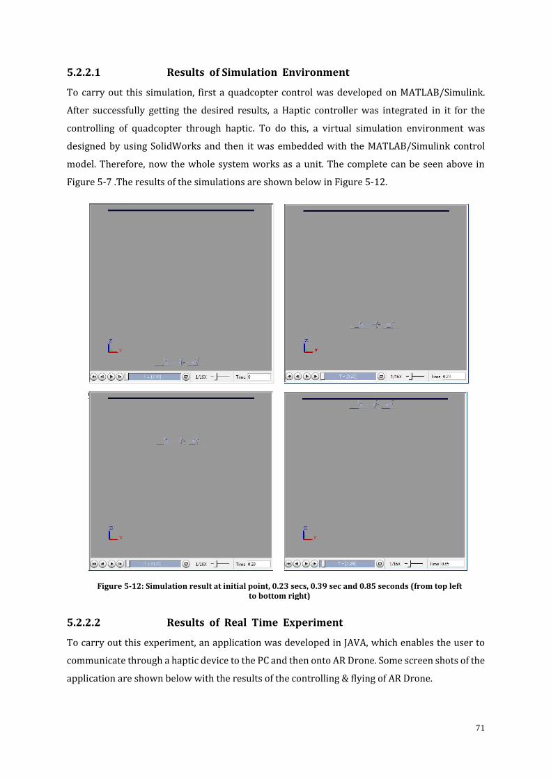
71
5.2.2.1 Results of Simulation Environment
To carry out this simulation, first a quadcopter control was developed on MATLAB/Simulink.
After successfully getting the desired results, a Haptic controller was integrated in it for the
controlling of quadcopter through haptic. To do this, a virtual simulation environment was
designed by using SolidWorks and then it was embedded with the MATLAB/Simulink control
model. Therefore, now the whole system works as a unit. The complete can be seen above in
Figure 5-7 .The results of the simulations are shown below in Figure 5-12.
5.2.2.2 Results of Real Time Experiment
To carry out this experiment, an application was developed in JAVA, which enables the user to
communicate through a haptic device to the PC and then onto AR Drone. Some screen shots of the
application are shown below with the results of the controlling & flying of AR Drone.
Figure 5-12: Simulation result at initial point, 0.23 secs, 0.39 sec and 0.85 seconds (from top left to bottom right)
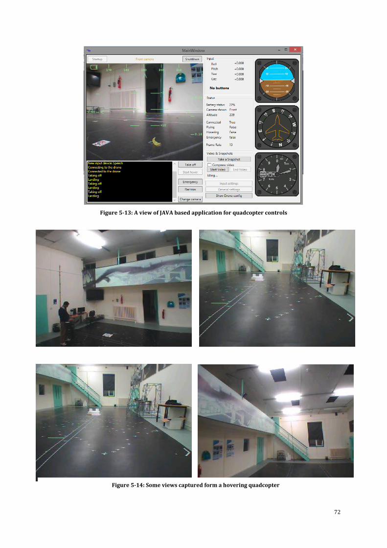
72
Figure 5-13: A view of JAVA based application for quadcopter controls
Figure 5-14: Some views captured form a hovering quadcopter
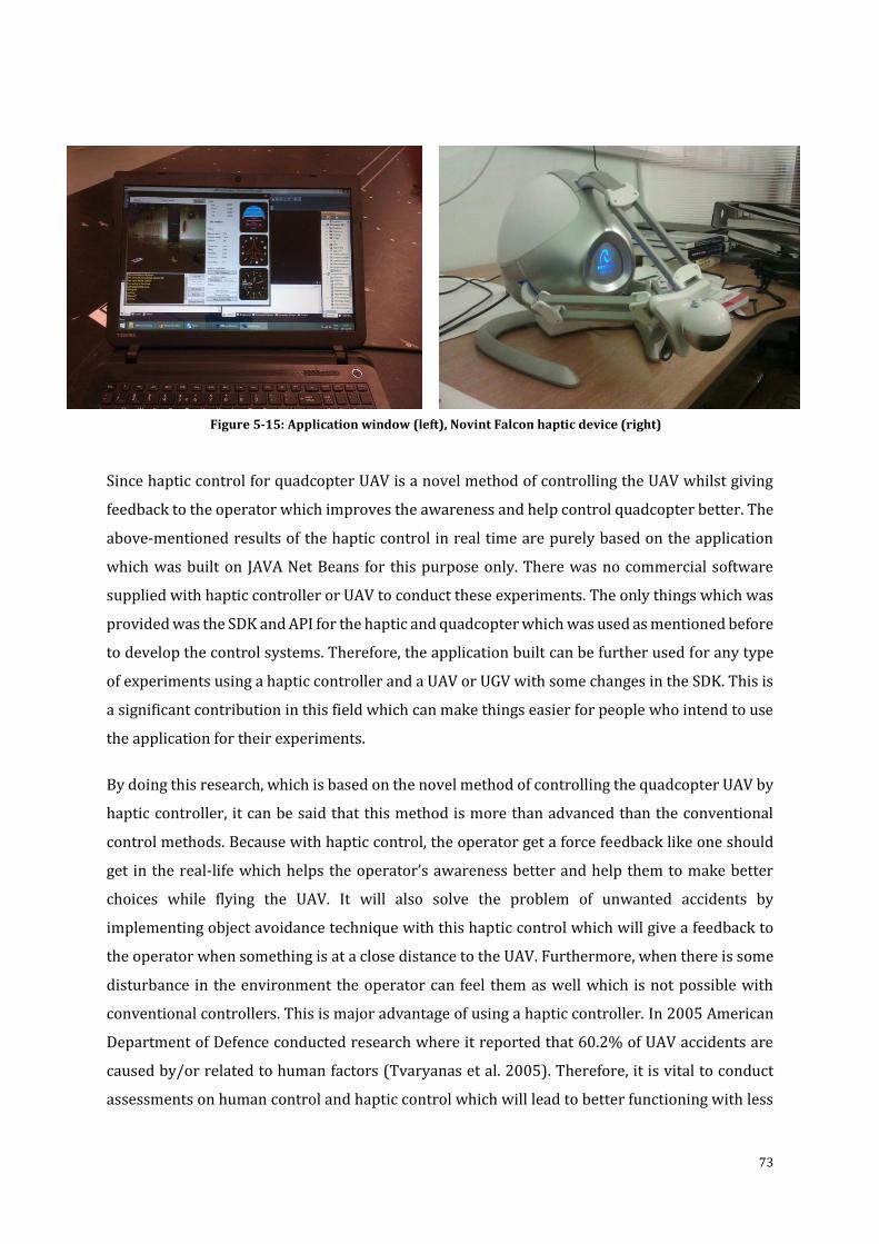
73
Since haptic control for quadcopter UAV is a novel method of controlling the UAV whilst giving
feedback to the operator which improves the awareness and help control quadcopter better. The
above-mentioned results of the haptic control in real time are purely based on the application
which was built on JAVA Net Beans for this purpose only. There was no commercial software
supplied with haptic controller or UAV to conduct these experiments. The only things which was
provided was the SDK and API for the haptic and quadcopter which was used as mentioned before
to develop the control systems. Therefore, the application built can be further used for any type
of experiments using a haptic controller and a UAV or UGV with some changes in the SDK. This is
a significant contribution in this field which can make things easier for people who intend to use
the application for their experiments.
By doing this research, which is based on the novel method of controlling the quadcopter UAV by
haptic controller, it can be said that this method is more than advanced than the conventional
control methods. Because with haptic control, the operator get a force feedback like one should
get in the real-life which helps the operator’s awareness better and help them to make better
choices while flying the UAV. It will also solve the problem of unwanted accidents by
implementing object avoidance technique with this haptic control which will give a feedback to
the operator when something is at a close distance to the UAV. Furthermore, when there is some
disturbance in the environment the operator can feel them as well which is not possible with
conventional controllers. This is major advantage of using a haptic controller. In 2005 American
Department of Defence conducted research where it reported that 60.2% of UAV accidents are
caused by/or related to human factors (Tvaryanas et al. 2005). Therefore, it is vital to conduct
assessments on human control and haptic control which will lead to better functioning with less
Figure 5-15: Application window (left), Novint Falcon haptic device (right)
74
accidents. The results in the above two sections clearly shows that this method is far superior
than the conventional controller since there is more guidance, awareness, data and control over
the UAV. Furthermore, the developed user control for real-time experiments Figure 5-3 can be
used for any type of robot (UAV or UGV) with haptic control by just changing the drivers in the
software for a robot and haptic and use it accordingly. It will be very useful for other researchers
in our Autonomous Laboratory to implement different control strategies on the built-in user
interface for various applications. In the future technology section in the next chapter, it is
mentioned what to look forward to in terms of more advanced controls of haptics and UAVs.
5.3 Conclusion In this chapter, the results obtained from the virtual simulation and real-time environment
experiments for the control and haptic system models were presented. It also defined how the PD
and PID controller were used and tuned to desired outputs. The results clearly show that the
method of using haptic to control the quadcopter is novel and it gives a clear picture of the control
that the user has on the system. The developed control can still be enhanced for future application
and their needs. Also, new haptic devices and quadcopters with more functions can be used to
perform tasks which were not possible right now and it can certainty improve the controlling on
quadcopter having additional capabilities. The conclusion with future development are discussed
in chapter 6.
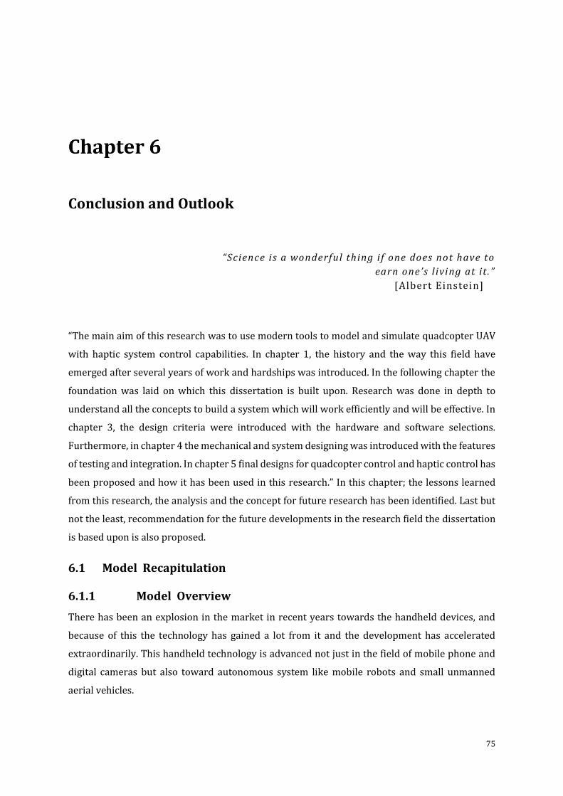
75
Conclusion and Outlook
“Science is a wonderful thing if one does not have to
earn one’s l iving at it .”
[Albert Einstein]
“The main aim of this research was to use modern tools to model and simulate quadcopter UAV
with haptic system control capabilities. In chapter 1, the history and the way this field have
emerged after several years of work and hardships was introduced. In the following chapter the
foundation was laid on which this dissertation is built upon. Research was done in depth to
understand all the concepts to build a system which will work efficiently and will be effective. In
chapter 3, the design criteria were introduced with the hardware and software selections.
Furthermore, in chapter 4 the mechanical and system designing was introduced with the features
of testing and integration. In chapter 5 final designs for quadcopter control and haptic control has
been proposed and how it has been used in this research.” In this chapter; the lessons learned
from this research, the analysis and the concept for future research has been identified. Last but
not the least, recommendation for the future developments in the research field the dissertation
is based upon is also proposed.
6.1 Model Recapitulation
6.1.1 Model Overview
There has been an explosion in the market in recent years towards the handheld devices, and
because of this the technology has gained a lot from it and the development has accelerated
extraordinarily. This handheld technology is advanced not just in the field of mobile phone and
digital cameras but also toward autonomous system like mobile robots and small unmanned
aerial vehicles.
76
Because of this, the research project which has been discussed in this report was born. Therefore,
to develop and simulation a quadcopter UAV with haptic system control, research findings from
the subjects like robotics, aerospace and control were studied and taken into consideration. To
design and develop a quadcopter it requires designing of control, model of quadcopter itself,
haptic controller and a level of optimisation.
The most important issue is the designing of vehicle dynamics for the controlling of quadcopter.
Therefore, research was done on system modelling, simulations & experiments and analysis. This
is needed to develop an elaborate system model and the best control approach that can be
adapted for the quadcopter model and control with haptics.
Firstly, the top to bottom approach was used to design the model of the quadcopter. Then couple
of system control were studied and adapted through simulations and analysis. Which gave us our
final system model for the quadcopter, on which haptic model was implemented, simulated and
analysed.
This whole research has been summarized below with each step taken, carefully researched,
developed, simulated and analysed to the best of their ability.
6.1.2 Execution of Requirements
The chapters above describe the requirements for designing and modelling the quadcopter UAV
control with haptic control capabilities using modern tools. Additionally, after all the research
and development carried out, it was seen that the development of the quadcopter will be easy in
the future. The project started with the development of a classical PD controller which was
simulated and analysed, and then it was further investigated and transformed into a PID
controller which was also simulated and analysed. Furthermore, after getting the desired results
from the quadcopter model, PID controller which further enhanced with sophisticated real like
control with haptic capability and then the system was tested and analysed. Here is the summary
of the characteristics and the requirements of this research project and how they were fulfilled
are shown below.
A. Designing
To start with, a CAD model was designed in SolidWorks for the quadcopter UAV having
precise physical parameters. This allowed us to extract information about the quadcopter
dynamics and control. Furthermore, the dynamics of the propellers and how the PMDC motor
works were also identified. It also helped us to understand how much power was required by
77
the motor to rotate the propeller, which gave us an idea of the battery needs to be used. On
the other hand, an application was designed for the haptic control to be used with the AR
Drone to see how exactly the quadcopter works in real life so it could be implemented in the
virtual environment for the quadcopter control based on haptic inputs. All of this has been
detailed in this report above.
B. Modelling
After gathering all the information from the designing investigation, system dynamics for
quadcopter control was modelled. Here it was decided to use two types of control models for
the quadcopter i.e. PD and PID, to understand the best available model for this project and
implement it further with the haptic control system. Simultaneously, the modelling for haptic
system control was looked at which has been already identified at the designing phase. The
implementation of control and haptics are discussed thoroughly above.
C. Control
The most important part of this project was to develop efficient and precise control for the
quadcopter model with haptic control system. After the designing and modelling phase, the
development of the control systems for the required models was done. The control systems
were the PD and PID controls. The PID turned out to be better and therefore it was selected
to be our main control system and implemented with the haptic control for further research.
The main reason for selection the PID controller was the efficiency, robustness and good
results in large disturbance. In the end the controller worked out well with the haptic control
and the results shows that the quadcopter is in stable condition and haptic control works well
which the quadcopter controls.
6.1.3 Novelty
In summary, the originality of this work lies in,
Easy Approach for Modelling Control System – The model of the quadcopter used in
this project has precise features like, aerodynamics, design of the quadcopter, and top to
bottom approach, which helped us understand the features of the quadcopter design
easily and the CAD model of the quadcopter which was designed to extract the accurately
correct parameters of the quadcopter. Hence, the development became very easy.
Single Technique for Full Control of Quadcopter – This project only uses a single full
control model for a quadcopter. As far as known, other systems which are available use
78
several control techniques. By using a single control, development becomes simple and
flexible and easy to manipulate.
Single Tool for All Simulation – The use of single tool was very helpful and a novelty in
terms of SolidWorks CAD model being used with MATLAB/Simulink which has not been
done before in my knowledge. MATLAB/Simulink is an excellent tool to build controls for
the quadcopter and for integration of the haptic and the virtual environment. This whole
project was completed on a single platform rather than working on different platforms
like one can see in prior research work conducted by other researchers.
Simultaneous working on Design and Control – The project used this method of
simultaneously working on both parts of designing and control. This made working
simpler to apply and when there is a problem it can be looked at the same time and
adjustment can be made to it. Alternately, one can do both parts separately which will be
a little quicker but when there is an error in the system at the end it will be difficult to
debug. Because one must go through the whole system again to find it. But in my case one
can check and solve it at the same time of designing.
Comparing different UAV control techniques – This research has compared only two
different control techniques as mentioned PD & PID. The difference between them is that
when PD controller is used it makes the quadcopter unsteady if there are large
disturbance and the quadcopter does not go back to its original state after the disturbance
has occurred. While PID doesn’t have this problem.
UAV responses in difference situation – If there are large disturbances such as heavy
gusts then the quadcopter may fail to fly properly because the quadcopter used in this
research cannot bear extreme changes in the weather conditions. The control developed
here is based on indoor flight configurations. If a more advanced UAV is used it will solve
this problem. Furthermore, if the battery in the quadcopter is changed to a heavier
battery, it will not change the response as the maximum weight of the battery that is
available in the market is about 623 grams for this type of quadcopter.
6.2 Recommendations and Hints for Future Research
The author previously mentioned in (Akhtar 2013) and still there is a wide range of topics that
still needs more research. While designing the undertaken model, number of topics were found
to be interesting that are worth looking into for more efficient control strategies and can perform
various other tasks by using different means for inputs (Akhtar 2013). “This potential of
improvement is outlined below in the report. It is better to start with the issues that can be solved
in the near future rather than starting at the highest point which is far for now.(Akhtar 2013)
Afterwards when one succeeds in these topics then they can focus on other more advance and
79
complex topics which also require long term commitment as well as help and effort from the
interdisciplinary areas such as UAV, electrical engineering, robotics, mechanical engineering and
more which may be due in time to come.”(Akhtar 2013)
Wireless System for Haptic Device
A wireless system for the Haptic Device can be one of the topics which have potential
to be researched on. It may be possible to use it through Bluetooth or Wi-Fi technology
to connect to the PC. This could make the usage better and can work where work
space is an issue.
Think Film Technology
“There is wide area for researching on FILM Skin technology. This film is flexible,
multifunctional, lightweight, integrated films. They allow feelings like hot and cold as
well as touch sensations (pressure). They work by using the vertical aligned Nano-
tubes. A breakthrough in this will be one of the major things that can change the face
of haptics”. (Akhtar 2013)
Solar-Powered UAVs
It may be possible that in near future that one will be able to see or use solar powered
UAVs. One of these kinds of UAV has just been developed for military use, but to make
it available in the consumer market will change the way UAVs are used.
6.3 Technologies in Use & Yet to Come
6.3.1 Current Technology
In recent years, there has been a major development in the field of UAVs for military and
consumer market. Different kinds of material are being used to design and develop these UAVs
due to the materials which were expensive before are inexpensive now and there are more
variety of application available for their use (Akhtar 2013). New kinds of aluminium and plastics
materials are being used which has made the vehicles lighter and stronger as well as less power
is required to operate them (Akhtar 2013).
It’s not only the material which has advanced but also there is a major advancement in electronics,
mechanics, optical instruments, sensors and etc. that are being used in the UAVs. There are much
more advanced camera available which can take pictures or videos in HD technology. Many
sensors which are available now like the distance measurement sensor, heat sensitivity sensors,
infra-red sensors, multispectral and hyper-spectral sensors and so on were not here before or
they were very expensive.
80
Mostly the quadcopter which are available for are quite brilliant for their specific applications.
There designs are extremely well thought and the capabilities they provide are enormous. One
can control a quadcopter with their mobile phones by using an app (such as command the
quadcopter to follow you around while you are running). It can also be used to do photography
and it’s what I have personally used it for. The future is very bright and soon many high tech
futuristic quadcopter or small consumer based UAVs will be available in the market.
On the other hand, the haptic controllers are booming with their own application in various
industries such as, medicine, aerospace, arts and so on. Right now the technology for medical
haptics is growing tremendously. One can see that, now to perform a surgery not even being
present in the same room as the patient is possible; it can be done remotely and this application
is going to grow quickly in the near future. Many different varieties of haptic controllers are
available for the use with quadcopter or any other flying/ground based robots. One can use it
remotely to perform various tasks and accomplish them with accuracy. The near future is very
promising and one should look towards it.
6.3.2 Future Technology
The author of this dissertation is not sure where the phase “the future is now” came from, but it
undoubtedly relates to UAV systems.
The UAV system since many decades thought to have been the last one to come up but now one
can say that it’s there to state its presence stay for a long long time. What the future holds for the
UAV systems is very promising as advancement is being done on day to day basis. The main
reason of this advancement is not because of good research in the field of UAV but it has happened
over the years in various other endeavours and this had led to the advancement in UAV
technology. The development is the field of material and miniaturisation has made it possible for
us to develop and integrate UAV for military and consumer based markets.
It is not easy to predict the future of these systems as in the past and present the systems were
built just because a customer or a researcher thought of it. May be there can be limitation in the
future due to public concerns and not because of technology constraints. As an example, people
are sceptical about replacing the aeroplane crew with an autonomous system. So right now, it will
be very foolish to do it, as people will not travel. This is going to take a long time and I think by
that time I will not be there to discuss this. However, some of the short future comings is a good
idea to discuss. Some of the control systems which will soon be implemented with the UAVs
control system may include,
81
Autonomous Mission Systems
Collision Avoidance System
Intelligent System Health Monitoring
Over the Horizon Communication System
Extra High Altitude
Formation Flight
Quick Deployment
Terrain Avoidance
All Weather Vehicles
Stealth Technology
Some Power Generation Systems of the future may include,
Electric Power (Lithium Sulphur rechargeable battery)
Fuel Cell Technology (its works a catalyst, which separates the electrons and
protons from electrolyte and force the electrons to go through the circuit,
converting them to electrical power)
There will be other enchantments which may include airframe configurations changes, optical
sensors, mechanical and electrical systems. As for haptic, the technology has surely evolved and
it is said to be estimated at 29 billion dollars by 2020.
6.4 Conclusion
This brings us to the conclusion of the thesis! Every day there are number of things that people
do which involves the use of haptics and they do not even think about it. Surely soon one will
think and use these various kinds of futuristic haptics devices and application in their daily life
which will benefit them in one way or another. On the other hand, the use of UAVs is increasing
day by day and since the technology is advancing so rapidly that from some years from now
everyone of use will have some kind of UAV for doing something specific that one desire which
may be taking photographs, playing real life video games with it, or even using it for security for
their own homes.
This report describes the concept of modelling and controlling of quadcopter UAV with haptic
system control using modern tools in virtual simulation and real time environments. The aim was
to design an efficient control system for quadcopter and equip it with natural pattern and
movements which precise parameters. Also, a control of haptics was investigated and developed
so quadcopter can be flown using the controls of haptic in real time and simulation environment.
Furthermore, the design shows that the implementation and development of quadcopter could
82
be done easily as well as there are many other options available which can be introduced into the
system after the first phase of development is done. At the moment, the concept is given with the
modelling and control features of the quadcopter with haptics using modern tools. When the
development of the quadcopter is carried out some mechanical, hardware and software test
should be done. It can enhance the concept for future applications where necessary. The proposed
design has met all the requirements of quadcopter model and control as well as haptics and there
is a great potential to implement this using modern tools and be successful in future.
(Arimot o 1996; B ohorquez et al. 2001; B ramwell et al. 2001; Ethkin & Reid 1996; Fra nkl in et al. 1997; G oldstein et al. 2001; Griffit hs & Leishman 2002; Gue nard et al. 2006; Hy nes et al. 2002; Leishma n 2006; M ullhaupt et al. 1999; Mul lha upt 1999; Nicoud & Zufferey 2002) (Ol fati-Sabe r 2001; Pounds & Mahony 2005; Pounds et al. 2006; Pounds, Mahony & Gre sham 2010; Pounds, Mahony & Corke 2010; Tanner 2003; Wa ng et al. 2006; Waslande r et al. 2005)
(Craig 2005; C. S. Ha & Lee 2013; Hokayem & Spong 2006; Korteling & Borg 1997; Lam et al. 2004; Lam et al. 2008) (Masone et al. 2012)

83
(Intentionally left blank)
84
….Into the Future
“Men, my brothers, men the workers, ever reaping something new;
That which they have done but earnest of the things that they shall do.
For I dipt into the future, far as human eye could see,
Saw the Vision of the world, and all the wonder that would be;
Saw the heavens fill with commerce, argosies of magic sails,
Pilots of the purple twilight, dropping down with costly bales;
Heard the heavens fill with shouting, and there rain’d a ghastly dew
From the nations’ airy navies grappling in the central blue;
Far along the world-wide whisper of the south-wind rushing warm,
With the standards of the peoples plunging thro’ the thunder-storm;
Till the war-drum throbb’d no longer, and the battle-flags were furl’d
In the Parliament of man, the Federation of the world.
There the common sense of most shall hold a fretful realm in awe,
And the kindly earth shall slumber, lapt in universal law”.
From ‘Locksley Hall’, written by Alfred, Lord Tennyson in the 1830s.
“Unlike Tennyson, the author of this paper has no crystal ball to tell what the future holds, but the
hope for living in the better society still lives on the basic faith that legislators and engineers will
work together to enable the safe applications of unmanned aircraft systems for civilian uses and
to their benefits, rather than the destruction, of humanity”.

85
(Intentionally left blank)
86
Bibliography
Ackerman, E., 2011. Freaky Boneless Robot Walks on Soft Legs. Available at: http://spectrum.ieee.org/automaton/robotics/military-robots/freaky-boneless-robot-walks-on-soft-legs [Accessed April 2, 2014].
Akhtar, S.N., 2013. A Bionic Model of Human Arm & The Measurement of EMG Signals. Queen Mary, University of London.
Altug, E., Ostrowski, J.. & Taylor, C.., 2005. Control of a quadrotor helicopter using dual camera visual feedback. International Journal of Robotics Research, 25(5), pp.329–341.
Amir, M.Y. & Abbass, V., 2008. Modeling of quadrotor helicopter dynamics. ICSMA 2008 - International Conference on Smart Manufacturing Application, pp.100–105.
Anon, 2005. Aircraft Classification. An Illustrated Dictionary of Aviation - McGraw-Hill Companies. Available at: http://encyclopedia2.thefreedictionary.com/aircraft+classification [Accessed July 16, 2014].
Anon, 2012a. Contraction of Euler angles. Drone Project. Available at: www.open-drone/gallery [Accessed July 2, 2014].
Anon, 2014. Electronics Teacher. Available at: http://www.electronicsteacher.com/ [Accessed March 27, 2014].
Anon, 2012b. History of the Helicopter from Concept to Modern Day. Prime Industries. Available at: http://primeindustriesusa.com/history-of-the-helicopters/ [Accessed April 1, 2014].
Anon, 2013a. Permanent Magnet DC Motor. Circuit Globle. Available at: http://circuitglobe.com/permanent-magnet-dc-motor.html [Accessed December 27, 2016].
Anon, 2013b. Quad-rotor concept motion. Hindawi. Available at: http://www.hindawi.com/journals/ijae/2011/214549/fig11/ [Accessed July 5, 2014].
Anon, 2015. Quadcopter Parts List | What You Need to Build a DIY Quadcopter. Quadcopter Garage. Available at: http://quadcoptergarage.com/quadcopter-parts-list-what-you-need-to-build-a-diy-quadcopter/ [Accessed August 19, 2014].
Arimoto, S., 1996. Control Theory of Non-linear Mechanical Systems, OUP Oxford Science.
Asaro, 2008. House Hold Robots. Available at: http://asaro.wordpress.com/2008/01/29/household-robots-or-future-persons/ [Accessed April 23, 2014].
Asmat, C., 2012. The Future of Robotics. Available at: http://www.robotshop.com/blog/en/the-future-of-robotics-as-forbes-sees-it-1733 [Accessed March 29, 2014].
Beard, R., 2008. Quadrotor Dynamics and Control, Utah, USA.
Becker, M. & Siegwart, R., 2006. Autonomous Miniature Flying Robots. IEEE Robotics and Automation Magazine, pp.1–8.
Billinghurst, M. & Furness, T.A., 2015. The Human Interface Technology Lab. Available at: http://www.hitl.washington.edu/projects/ [Accessed September 6, 2014].
Birnbaum, D., 2016. Creative Haptic Expressions: Trends and Tools. In IEEE Haptics Symposium. Philadelphia, Pennsylvania, USA: IEEE. Available at: https://www.immersion.com/events/ieee-haptics-symposium-2016/.
Bohorquez, F. et al., 2001. Design, Analysis and Performance of a Rotary Wing MAV. Johns
87
Hopkins University - Applied Physics.
Bouabdallah, S., Murrieri, P. & Seigwart, R., 2004. Design and control of an indoor micro quadrotor. In IEEE Conference on Robotics & Automation. New Orleans, USA.
Bramwell, A.R.S., Done, G. & Balmford, D., 2001. Bramwell’s Helicopter Dynamics 2nd ed., American Institute of Aeronautics & Ast.
Brandt, A.M. & Colton, M.B., 2010. Haptic collision avoidance for a remotely operated quadrotor UAV in indoor environments. Conference Proceedings - IEEE International Conference on Systems, Man and Cybernetics, pp.2724–2731.
Brumson, B., 2011. Unique Robotics Applications. Available at: http://www.robotics.org/content-detail.cfm/Industrial-Robotics-Industry-Insights/Unique-Robotic-Applications/content_id/2572 [Accessed May 15, 2014].
Byko, M., 2008. Personification: The Materials Science and Engineering of Humanoid Robots. Available at: http://www.tms.org/pubs/journals/JOM/0311/Byko-0311.html [Accessed April 12, 2014].
Castillo, P., Lozano, R. & Dzul, A., 2005. Stabilisation of a mini rotorcraft with four rotors. IEEE Control Systems Magazine, pp.45–55.
Cheeseman, I.. & Bennett, W.., 1957. The effect of the ground on a helicopter rotor in forward flight, London: HER MAJESTY’S OFFICE.
Claret, J., Zaplana, I. & Basa, L., 2016. Teleoperating a mobile manipulator and a free-flying camera from a single haptic device *. Conference Proceedings - IEEE International Symposium on Safety, Security and Rescue Robotics (SSRR), pp.291–296.
Craig, J.., 2005. Introduction to Robotics: Mechanics and Control. Prentice Hall, 3, pp.135–164.
Digg, 2014. Flight Configurations. Aero QUad. Available at: http://aeroquad.com/showwiki.php?title=Flight-Configurations [Accessed August 8, 2014].
Dikmen, I.., Arisoy, A. & Temeltas, H., 2009. Attitude control of a quadrotor. In 4th International Conference on Recent Advances in Space Technologies. pp. 722–727.
DraganFly, 2014. Dragan Flyer. Available at: http://www.draganfly.com/ [Accessed May 8, 2014].
Drone, A., 2015. AR Drone Academy. Parrot SA. Available at: http://blog.parrot.com/ [Accessed August 23, 2014].
Elfes, A. et al., 2003. Robotic Airships for Exploration of Planetary Bodies with an Atmosphere: Autonomy Challenges. Autonomous Robots, 14(2), pp.147–164. Available at: http://dx.doi.org/10.1023/A:1022227602153.
Erginer, B. & Altug, E., 2007. Modeling and PD Control of a Quadrotor VTOL Vehicle. 2007 IEEE Intelligent Vehicles Symposium, pp.894–899.
Escare, J., Salazar-Cruz, C. & Lozano, R., 2006. Embedded control of a four-rotor UAV. American Control Conference, 4(11), pp.3936–3941.
Ethkin, B. & Reid, L., 1996. Dynamics of Flight: Stability and Control, John Wiley and Sons.
Falcon, N., 2014. Novint Falcon Haptic Device. Novint Technologies. Available at: www.novint.com/ [Accessed April 16, 2014].
Fay, G., 2001. Derivation of the aerodynamics forces for the mesicopter simulation, USA.
Franklin, F.G., Powell, J.D. & Workman, L.M., 1997. Digital Control of Dynamic Systems 3rd ed., Prentice Hall.
88
Fu, S. et al., 2016. A haptic interface with adjustable feedback for unmanned aerial vehicles (UAVs) -model, control, and test. Proceedings of the American Control Conference, 2016–July, pp.467–472.
Gadget, 2010. AR Drone Parrot 2.0 Review. Electricpig. Available at: http://www.electricpig.co.uk/2010/07/19/parrot-ar-drone-review/parrot-ar-drone-review-6/index.html [Accessed August 11, 2014].
Gazette, A., 2010. Mars Rover. Available at: http://arabiangazette.com/mars-rover-2010.htm [Accessed March 23, 2014].
Geomagic, 2013. GeoMagic Touch Haptic Controller. 3DS GeoMagic. Available at: http://www.geomagic.com/en/products/phantom-omni/overview [Accessed January 1, 2015].
Goldstein, H., Poole Jr., C.P. & Sakfo, J.L., 2001. Classical Mechanics 3rd ed., Pearson.
Grabe, V. et al., 2013. The TeleKyb framework for a modular and extendible ROS-based quadrotor control. 2013 European Conference on Mobile Robots, ECMR 2013 - Conference Proceedings, pp.19–25.
Griffiths, D. & Leishman, J., 2002. A study of dual-rotor interference and ground effect using a free-vortex wake model. In 58th Annual Forum of the American Helicopter Society. Montreal, Canada.
Guenard, N., Hamel, T. & Eck, L., 2006. Control laws for the teleoperation of an unmanned aerial vehicle known as an x4-flyer. In IEEE Conference on Intelligent Robots and Systems. Beijing, China.
Ha, C. & Lee, D., 2013. Vision-based teleoperation of unmanned aerial and ground vehicles. Proceedings - IEEE International Conference on Robotics and Automation, pp.1465–1470.
Ha, C.S. & Lee, D., 2013. Preliminary result of vision-based teleoperation of an UAV and UGVs team. 2013 10th International Conference on Ubiquitous Robots and Ambient Intelligence (URAI), pp.128–128. Available at: http://ieeexplore.ieee.org/lpdocs/epic03/wrapper.htm?arnumber=6677492.
He, R., Prentice, S. & Roy, N., 2008. Planning in information space for a quadrotor helicopter in a GPS-denied environment. In IEEE Conference on Robotics & Automation. pp. 1814–1820.
Hoffmann, G.. et al., 2007. Quadrotor helicopter flight dynamics and control: Theory and experiment. In Proceedings of AIAA Guidance, Navigation & Control Conference & Exhibit.
Hokayem, P. & Spong, M., 2006. Bilaternal Teleoperation: A historical Survey. Automatica, 42(12), pp.2035–2057.
Hsu, J., 2009. Real Soldiers Love Their Robot Brethren. Available at: http://www.axisoflogic.com/artman/publish/printer_55830.shtml [Accessed March 29, 2014].
Hua, M.D. et al., 2009. A control approach for thrust-propelled underactuated vehicles and its application to vtol drones. IEEE Transactions on Automatic Control, 54(8), pp.1837–1853.
Hua, M.D. & Rifai, H., 2010. Obstacle Avoidance for Teleoperated Underactuated Aerial Vehicles using Telemetric Measurement. In IEEE Conference on Control and Decision. pp. 262–267.
Huang, H. et al., 2009. Aerodynamics and control of autonomous quadrotor helicopters in aggressive manoeuvring. In IEEE Conference on Robotics & Automation. pp. 3277–3282.
Hynes, P. et al., 2002. Design of a four-rotor aerial robot. In Australasian Conference on Robotics & Automation. Auckland, New Zealand.
Juraj, G., 2013. Quadrotor Representations. Posterus. Available at:
89
http://www.posterus.sk/?p=14434 [Accessed September 5, 2014].
Kanso, A. et al., 2015. Enhanced teleoperation of UAVs with haptic feedback. IEEE/ASME International Conference on Advanced Intelligent Mechatronics, AIM, 2015–Augus, pp.305–310.
Khan, M., 2014. Quadcopter Flight Dynamics. International Journal of Scientific & Technology Research, 3(8), pp.130–135.
Kiran, D., 2016. Permanent Magnet DC (PMDC) Motors. DC Machines, Miscellaneous Machines. Available at: http://www.electricaleasy.com/2014/12/permanent-magnet-dc-pmdc-motors.html.
Korteling, J.E. & Borg, W. Van Der, 1997. Partial Camera Automation in an Unmanned Air Vehicle. IEEE Transactions on Systems, Man and Cybernetics - PART A: Systems and Humans, 27(2), pp.256–262.
Lam, T.M. et al., 2009. Artificial Force Field for Haptic Feedback in UAV Tele-operation. IEEE Transactions on Systems, Man and Cybernetics - PART A: Systems and Humans, 39(6), pp.1316–1330.
Lam, T.M. et al., 2004. Effect of haptic feedback in a trajectory following task with an unmanned aerial vehicle. Conference Proceedings - IEEE International Conference on Systems, Man and Cybernetics, 3, pp.2500–2506.
Lam, T.M., Mulder, M. & Van Paassen, M.M., 2007. Collision avoidance in uav tele-operation with time delay. Conference Proceedings - IEEE International Conference on Systems, Man and Cybernetics, pp.997–1002.
Lam, T.M., Mulder, M. & Van Paassen, M.M., 2008. Haptic feedback in uninhabited aerial vehicle teleoperation with time delay. AIAA Journal of Guidance, Control & Dynamics, 31(6), pp.1728–1739.
Lam, T.M., Mulder, M. & Van Paassen, M.M., 2009. Haptic interface in UAV tele-operation using force-stiffness feedback. Conference Proceedings - IEEE International Conference on Systems, Man and Cybernetics, (October), pp.835–840.
Lee, D. et al., 2011. Haptic teleoperation of multiple unmanned aerial vehicles over the internet. Proceedings - IEEE International Conference on Robotics and Automation, pp.1341–1347.
Lee, D., Franchi, A., et al., 2013. Semiautonomous haptic teleoperation control architecture of multiple unmanned aerial vehicles. IEEE/ASME Transactions on Mechatronics, 18(4), pp.1334–1345.
Lee, D., Ha, C. & Zuo, Z., 2013. Backstepping Control of Quadrotor-Type UAVs and Its Application to Teleoperation over the Internet. In S. Lee et al., eds. Intelligent Autonomous Systems 12: Volume 2 Proceedings of the 12th International Conference IAS-12, held June 26-29, 2012, Jeju Island, Korea. Berlin, Heidelberg: Springer Berlin Heidelberg, pp. 217–225. Available at: http://dx.doi.org/10.1007/978-3-642-33932-5_21.
Leishman, J.G., 2006. Principles of Helicopter Aerodynamics 2nd ed., Cambridge, UK: Cambridge University Press.
Li, J. & Li, Y., 2011. Dynamics Analysis and PID Control of a Quadrotor. In IEEE International Conference on Mechatronics & Automation. China.
Madani, T. & Benallegue, A., 2006. Back-stepping control for a quadrotor helicopter. In IEEE Conference on Robotics & Automation. pp. 3255–3260.
Mahony, R. et al., 2009. A new framework for force feedback teleoperation of robotic vehicless based on optical flow. In Conference Proceedings - IEEE International Conference on Robotics & Automation (ICRA). pp. 1079–1085.
90
Maria, 2014. Guide to drone autopilots - Flight Controllers. Drone Test. Available at: http://www.dronetrest.com/cf/beginners-guide-to-drone-autopilots-flight-controllers/1355 [Accessed July 26, 2014].
Martin, P. & Salaum, E., 2010. The true role of accelerometer feedback in quadrotor control. In IEEE Conference on Robotics & Automation. pp. 1623–1629.
Masone, C. et al., 2012. Interactive planning of persistent trajectories for human-assisted navigation of mobile robots. In IEEE Conference on Intelligent Robots and Systems. pp. 2641–2648.
Masone, C. et al., 2014. Semi-autonomous Trajectory Generation for Mobile Robots with Integral Haptic Shared Control. Conference Proceedings - IEEE International Conference on Robotics & Automation (ICRA), pp.6468–6475.
MathWorks, 2012. MATLAB/Simulink. The MathWorks Inc. Available at: https://www.mathworks.com/ [Accessed January 19, 2015].
Mersha, A.., Stramigioli, S. & Carloni, R., 2012. Bilateral Teleoperation of Underactuated Unmanned Aerial Vehicles: The virtual Slave Concept. In IEEE Conference on Robotics & Automation. pp. 4614–4620.
Mghabghab, S. & Asmar, D., 2016. Adaptive Gain Tuning for Teleoperation of Quadrotors. Conference Proceedings - IEEE International Multidisciplinary Conference on Engineering Technology (IMCET).
Mullhaupt, P., 1999. Analysis and Control of Under-actuated Mechanical Non-minimum-phase Systems. École polytechnique fédérale de Lausanne.
Mullhaupt, P. et al., 1999. Cascade control of the toycopter. In European Control Conference. Karlsruhe, Germany, pp. 1010–1012.
Multipilot, 2011. Quad-Frame-Assembly. Ardupilot Git Hub. Available at: https://code.google.com/archive/p/multipilot32/wikis/Quad_Frame_Assembly.wiki [Accessed September 23, 2014].
Nicoud, J. & Zufferey, J., 2002. Toward indoor flying robots. In IEEE Conference on Intelligent Robots and Systems. Lausanne, Switzerland.
Niemeyer, G., Preusche, C. & Hirzinger, G., 2008. Telerobotics. Springer Handbook of Robotics, B.Sicilian, pp.741–757.
Noth, A. & Seigwart, R., 2004. PID vs LQ control techniques applied to an indoor micro quadrotor. IEEE Conference on Intelligent Robots and Systems, 3, pp.2451–2456.
Olfati-Saber, R., 2001. Nonlinear Control of Under-actuated Mechanical Systems with Application to Robotics and Aerospace Vehicles. MIT.
Omari, S. et al., 2013. Bilateral haptic teleoperation of VTOL UAVs. Proceedings - IEEE International Conference on Robotics and Automation, pp.2393–2399.
Patel, A., Patel, M. & Vyas, D., 2012. Modelling and Analysis of Quadrotor using Slide Mode Control. In IEEE Southeastern Symposium on System Theory. North Florida, USA.
Peters, S., 2009. Space Camp. Available at: http://spacecamp2009.wordpress.com/take-a-robot-home/automated-guided-vehicle/ [Accessed March 27, 2014].
Phan-Dang, K., 2013. Autopilot Quadcopter. Robotics - Toradex. Available at: https://challenge.toradex.com/projects/10078-autopilot-quadcopter [Accessed October 27, 2014].
Pounds, P. & Mahony, R., 2005. Small-scale aero-elastic rotor simulation, design and fabrication. In Australian Conference on Robotics & Automation. Sydney, Australia: Australian Robotics
91
& Automation Association (ARAA).
Pounds, P., Mahony, R. & Corke, P., 2010. Modelling and Control of a Large Quadrotor Robot. Control Engineering Practice (Special Issue on Aerial Robotics), 18(7), pp.691–699.
Pounds, P., Mahony, R. & Corke, P., 2006. Modelling and Control of a Quad-Rotor Robot. In Australian Conference on Robotics & Automation. Auckland, New Zealand: Australian Robotics & Automation Association (ARAA).
Pounds, P., Mahony, R. & Gresham, J., 2010. Towards dynamically-favourable quad-rotor aerial robots. In Australian Conference on Robotics & Automation. Canberra, Australia: Australian Robotics & Automation Association (ARAA).
Raffo, G.., Ortega, M.. & Rubio, F.., 2010. An integral predictive/nonlinear H1 control structure for a quadrotor helicopter. Automatica, 46(1), pp.29–39.
Rifai, H. et al., 2011. Haptic-based Bilateral Teleoperation of Underactuated Unmanned Aerial Vehicles. In IFAC World Congress, Italy. pp. 13782–13788.
Robotics, A., 2011. Robotic Fishing. Available at: http://www.avr-vr.com/contri/view/en/expertise/robotic-finishing/ [Accessed April 4, 2014].
Rosenstein, E., 2013. Audrino Copter. Pinterest. Available at: https://uk.pinterest.com/pin/559501953677635356/ [Accessed February 15, 2015].
Rüesch, A., Mersha, A.Y. & Stramigioli, S., 2012. Kinetic scrolling-based position mapping for haptic teleoperation of unmanned aerial vehicles. In IEEE Conference on Robotics & AutomationEE International Conference on. Minnesota, USA.
Sam, 2014. Electronic Speed Controller for Multirotor. Drone Test. Available at: http://www.dronetrest.com/t/what-to-consider-when-buying-a-esc-for-your-multirotor/1305 [Accessed June 18, 2014].
Samuel, P. et al., 2005. Design and testing of a rotary wing mav with an active structure for stability and control. In AHS 61st Annual Forum. Gapevine, USA.
ScarLiang, 2012. BUILD A QUADCOPTER FROM SCRATCH – HARDWARE OVERVIEW. Share Knowledge and Ideas. Available at: https://oscarliang.com/build-a-quadcopter-beginners-tutorial-1/ [Accessed July 3, 2014].
Schill, F. et al., 2009. Visual Force Feedback Teleoperation of the Insectbot Using Optic Flow. In Australian Conference on Robotics & Automation.
Seigwart, R., 2007. Full Control of a Quadrotor. In IEEE Conference on Intelligent Robots and Systems. California, USA.
Siegwart, R. & Nourbakhsh, I., 2004. Introduction to Autonomous Mobile Robots Edition 2., MIT Press. Available at: http://books.google.com/books?hl=en&lr=&id=gUbQ9_weg88C&oi=fnd&pg=PR11&dq=Introduction+to+Autonomous+mobile+robot&ots=X3G7QFra6H&sig=E4S-0Wa2GmqdCqPT00oRd0N2SWA.
Skogestad, 2003. Simple analytic rules for model reduction and PID controller tuning. Journal of Process Control, 13(4), pp.291–309.
Stamper, R.., 1997. A Three Degree of Freedom Parallel Manipulator with Only Translational Degrees of Freedom. University of Maryland, College Park, MD.
Stegagno, P. et al., 2015. A Semi-autonomous UAV Platform for Indoor Remote Operation with Visual and Haptic Feedback. Conference Proceedings - IEEE International Conference on Robotics & Automation (ICRA), pp.3862–3869.
Stramigioli, S., Mahony, R. & Corke, P., 2010. A Novel Approach to Haptic Teleoperation of Aerial
92
Robot Vehicles. In IEEE Conference on Robotics & Automation. pp. 5302–5308.
Tanner, O., 2003. Modelling, Identification and Control of Autonomous Helicopters. Swiss Federal Institute of Technology ZURICH.
Tayebi, A. & McGilvray, S., 2004. Attitude stabilization of a four-rotor aerial robot. 43rd IEEE Conference on Decision and Control, 2, pp.1216–1221.
Tech, U., 2014. LiPo Batteries - A guide to using and looking after your batteries. Drone Test. Available at: http://www.dronetrest.com/t/lipo-batteries-a-guide-to-using-and-looking-after-your-batteries/1278 [Accessed June 1, 2014].
Touch, G., 2013. 3DS Haptic Systems. GeoMagic Touch. Available at: http://www.3dsystems.com/ [Accessed September 5, 2014].
Tvaryanas, A.P., Thompson, B.T. & Constable, S.H., 2005. U.S. Military Unmanned Aerial Vehicle Mishaps: Assessment of the Role of Human Factors Using HFACS, Washington D.C.
Valavanis, K.., 2007. Advances in Unmanned Aerial Vehicles: State of the Art and the Road to Autonomy. Springer Intelligent Systems, Control and Automation: Science and Engineering, 33.
Wang, W., Song, G. & Nonami, K., 2006. Autonomous Control for Micro-Flying Robot and Small Wireless Helicopter X.R.B. In IEEE Conference on Intelligent Robots and Systems. Beijing, China.
Waslander, S.. et al., 2005. Multi-agent quadrotor test-bed control design: Integral sliding mode vs. reinforcement learning. In IEEE Conference on Intelligent Robots and Systems. Edmonton, Canada.
Watkinson, J., 2003. Art of the Helicopter 1st ed., Butterworth-Heinemann.
WikiRos, 2013. Robot Operating System (ROS). ROS Organisation. Available at: http://wiki.ros.org/ [Accessed October 13, 2014].
Zauner, K.-P., Vaughan, A. & Cooke, E., 2012. Formica: Affordable, open source swarm robotics. Available at: http://warrantyvoidifremoved.com/formica [Accessed April 7, 2014].
Zemalache, K.., Beji, L. & Marref, H., 2005. Control of an under-actuated system: Application to a four rotors rotorcraft. In IEEE Conference on Robotics & Biomimetics. pp. 404–409.
Zuo, Z., 2010. Trajectory tracking control design with command-filtered compensation for a quadrotor. IET Control Theory & Applications, 4(11), pp.2343–2355. Available at: http://digital-library.theiet.org/content/journals/10.1049/iet-cta.2009.0336.
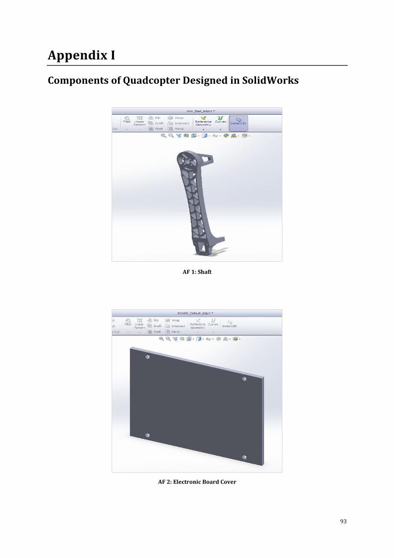
93
Appendix I
Components of Quadcopter Designed in SolidWorks
AF 1: Shaft
AF 2: Electronic Board Cover
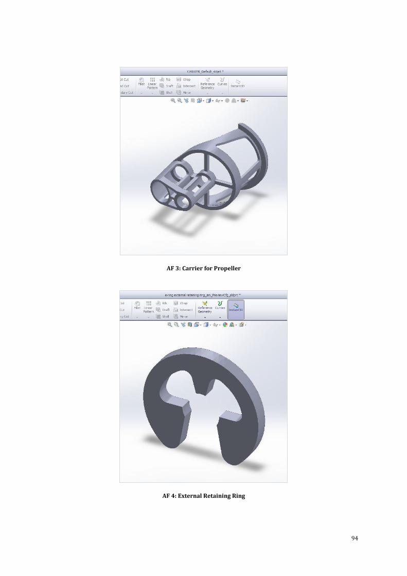
94
AF 3: Carrier for Propeller
AF 4: External Retaining Ring
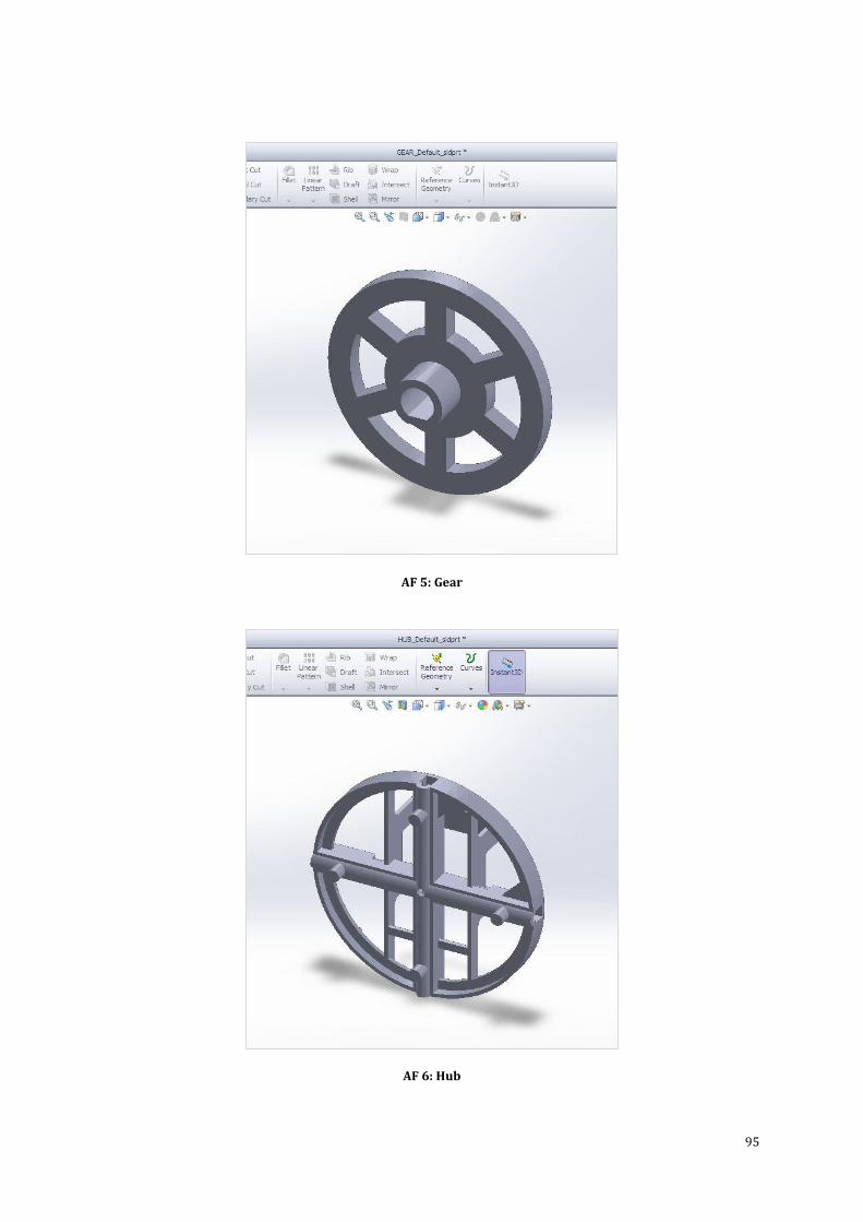
95
AF 5: Gear
AF 6: Hub
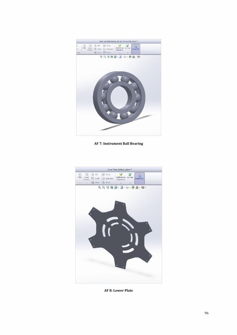
96
AF 7: Instrument Ball Bearing
AF 8: Lower Plate
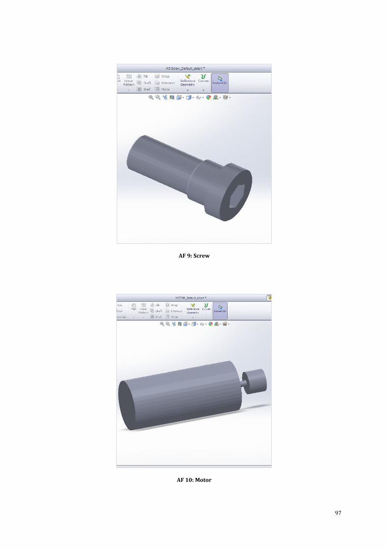
97
AF 9: Screw
AF 10: Motor
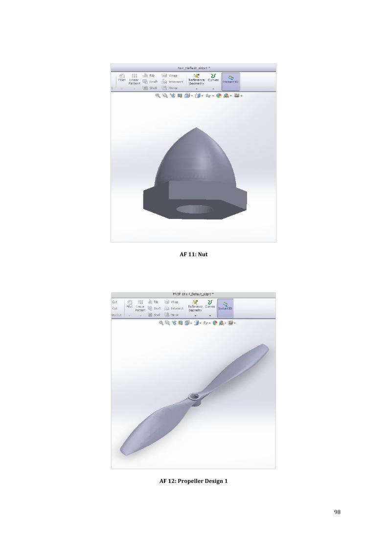
98
AF 11: Nut
AF 12: Propeller Design 1
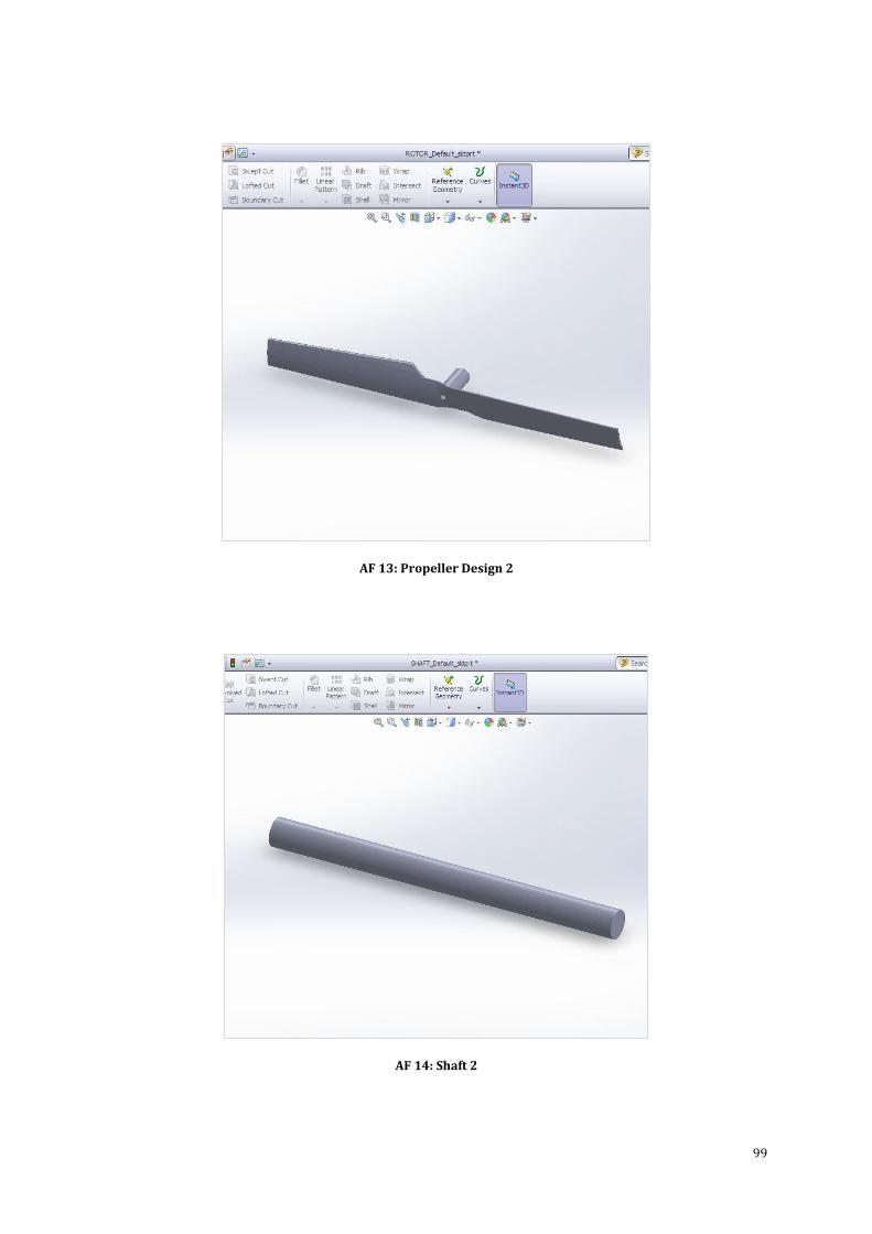
99
AF 13: Propeller Design 2
AF 14: Shaft 2
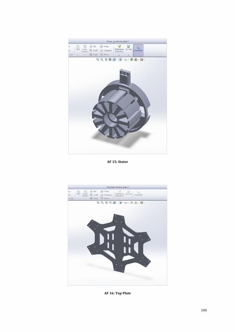
100
AF 15: Stator
AF 16: Top Plate
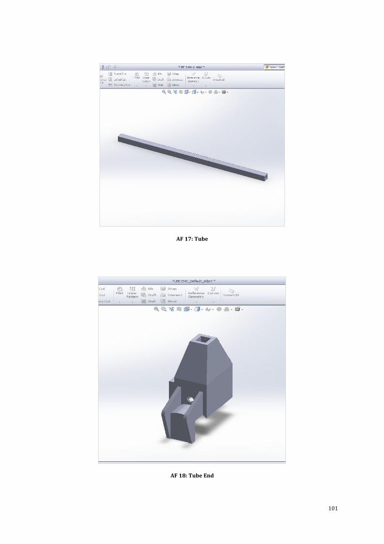
101
AF 17: Tube
AF 18: Tube End
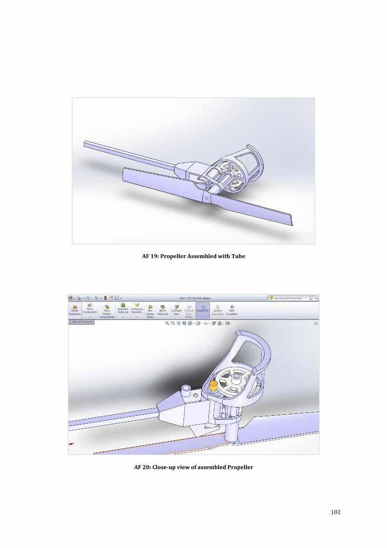
102
AF 19: Propeller Assembled with Tube
AF 20: Close-up view of assembled Propeller
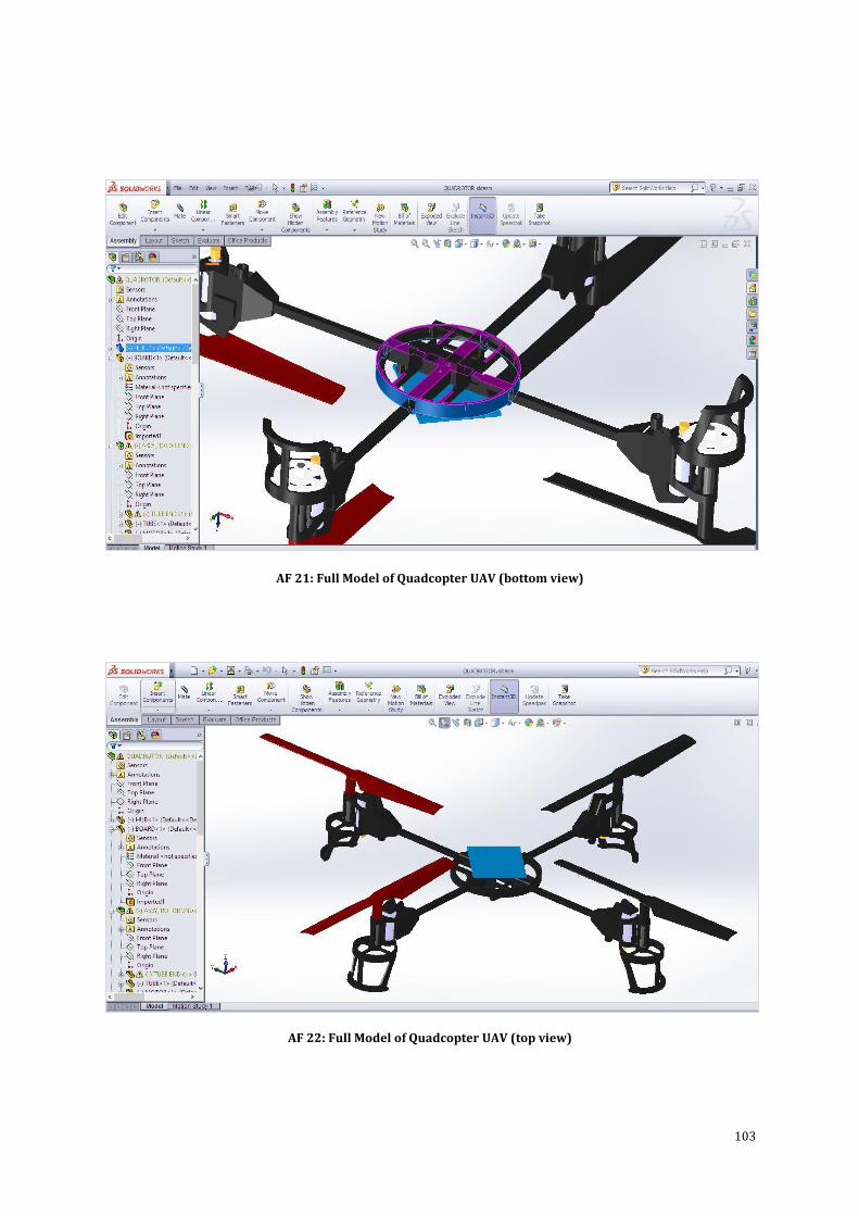
103
AF 21: Full Model of Quadcopter UAV (bottom view)
AF 22: Full Model of Quadcopter UAV (top view)
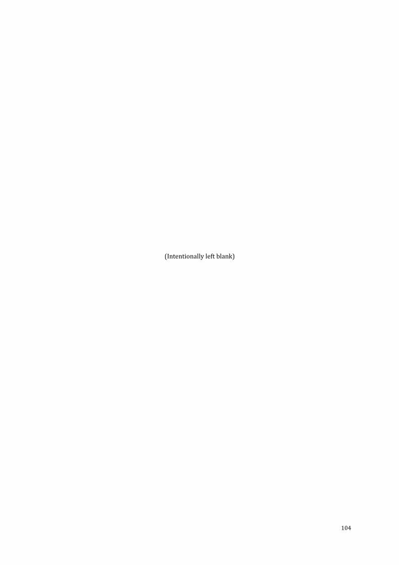
104
(Intentionally left blank)
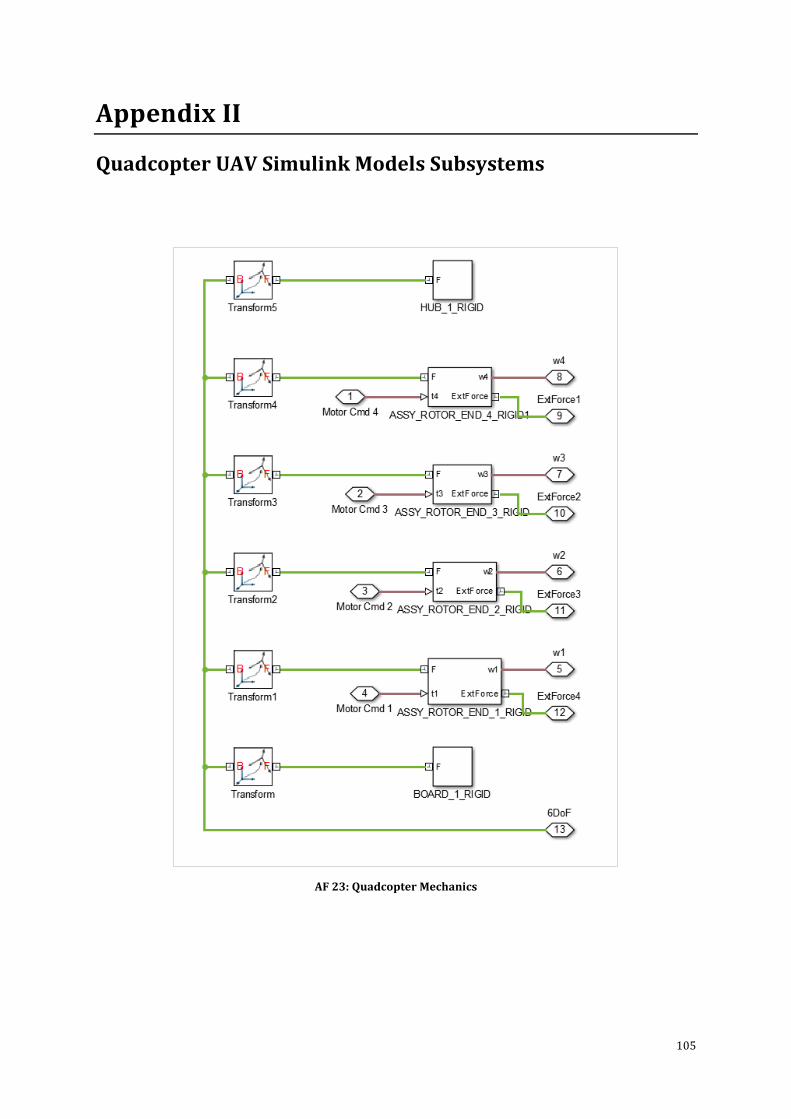
105
Appendix II
Quadcopter UAV Simulink Models Subsystems
AF 23: Quadcopter Mechanics
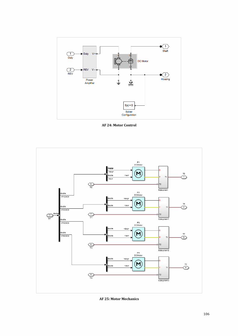
106
AF 24: Motor Control
AF 25: Motor Mechanics
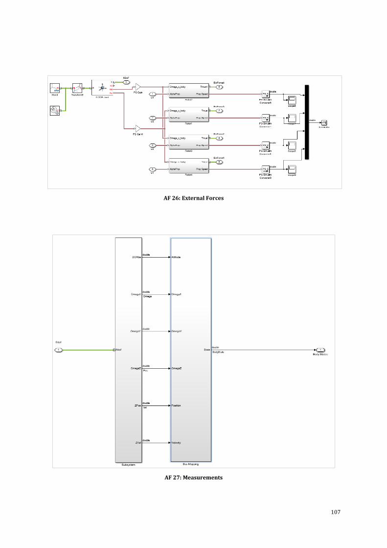
107
AF 26: External Forces
AF 27: Measurements
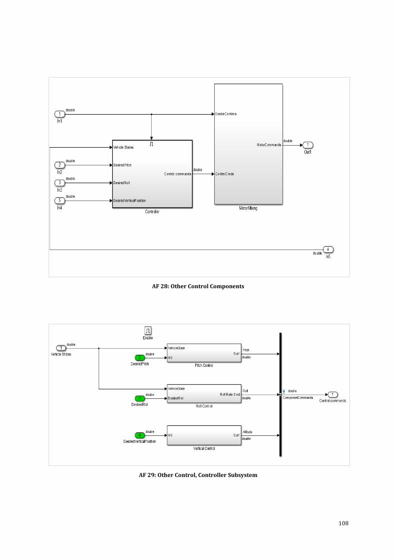
108
AF 28: Other Control Components
AF 29: Other Control, Controller Subsystem
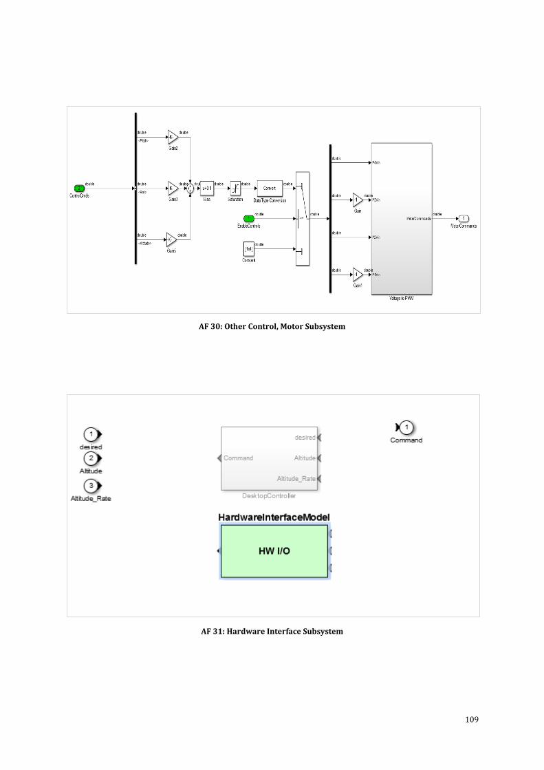
109
AF 30: Other Control, Motor Subsystem
AF 31: Hardware Interface Subsystem

110
(Intentionally left blank)
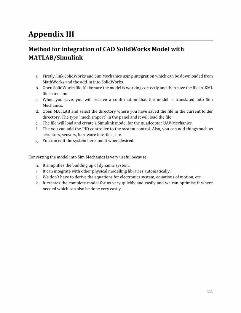
111
Appendix III
Method for integration of CAD SolidWorks Model with
MATLAB/Simulink
a. Firstly, link SolidWorks and Sim Mechanics using integration which can be downloaded from
MathWorks and the add-in into SolidWorks.
b. Open SolidWorks file. Make sure the model is working correctly and then save the file in .XML
file extension.
c. When you save, you will receive a confirmation that the model is translated into Sim
Mechanics.
d. Open MATLAB and select the directory where you have saved the file in the current folder
directory. The type “mech_import” in the panel and it will load the file
e. The file will load and create a Simulink model for the quadcopter UAV Mechanics.
f. The you can add the PID controller to the system control. Also, you can add things such as
actuators, sensors, hardware interface, etc.
g. You can edit the system here and it when desired.
Converting the model into Sim Mechanics is very useful because;
h. It simplifies the building up of dynamic system.
i. It can integrate with other physical modelling libraries automatically.
j. We don’t have to derive the equations for electronics system, equations of motion, etc.
k. It creates the complete model for us very quickly and easily and we can optimise it where
needed which can also be done very easily.
112
(Intentionally left blank)
113
Glossary
Actuation – to put into mechanical action or motion
Aerodynamics – is the study of how gases interact with moving bodies. Aerodynamics is primarily
concerned with the forces of drag and lift, which are caused by air passing over and around solid
bodies
Aerospace – is the human effort in science, engineering and business to fly in the atmosphere of Earth
(aeronautics) and surrounding space (astronautics)
Aluminium – is a chemical element in the boron group with symbol Al and atomic number 13
Angular speed – is the rate at which an object changes its angle (measured) in radians, in a given time
period.
Angular Displacement – is the angle that a rotating body goes through
Angular Velocity – is defined as the rate of change of angular displacement and is a vector quantity
(more precisely, a pseudo-vector) which specifies the angular speed (rotational speed) of an object
and the axis about which the object is rotating.
Artificial Intelligence – is the intelligence exhibited by machines or software. It is also the name of the
academic field of study which studies how to create computers and computer software that are
capable of intelligent behaviour
Barometer – is a scientific instrument used in meteorology to measure atmospheric pressure.
C language – C is a particularly popular language for personal computer programmers because it is
relatively small -- it requires less memory than other languages. Although it is a high-level language,
C is much closer to assembly language than are most other high-level languages
Carbon Fibre – is a material consisting of fibres about 5–10 micrometres in diameter and composed
mostly of carbon atoms.
Coaxial Rotors – are a pair of helicopter rotors mounted one above the other on concentric shafts,
with the same axis of rotation, but turning in opposite directions (contra-rotation).
Endeavour – A purposeful or industrious undertaking
Environment – the surroundings or conditions in which a person, animal, or plant lives or operates.
114
Fabrication – the action or process of manufacturing or inventing something.
Fixed Wing – A fixed-wing aircraft is a kind of aircraft. An aircraft is a machine that can fly, but is
heavier than air. Fixed-wing aircraft are sometimes called just planes. All fixed-wing aircraft have
wings.
Haptics – is Quite Literally The Science of Touch. The origin of the word haptics is the Greek haptikos,
meaning able to grasp or perceive. Haptic sensations are created in consumer devices by actuators,
or motors, which create a vibration.
JAVA – General purpose, high-level, object-oriented, cross-platform programming language
Manoeuvrability – a movement or series of moves requiring skill and care.
Miniaturization – is the trend to manufacture ever smaller mechanical, optical and electronic
products and devices. Examples include miniaturization of mobile phones, computers and vehicle
engine downsizing.
OOP – Object oriented programming
Open source – The codes are available online and can be used by anyone
Payload – he part of a vehicle's load, especially an aircraft's, from which revenue is derived;
passengers and cargo.
Pitch Movement – Rotation around the side to side axis
Platform independent – The software programs can be executed in my operating system
Plywood – is a sheet material manufactured from thin layers or "plies" of wood veneer that are glued
together with adjacent layers having their wood grain rotated up to 90 degrees to one another.
Proportional – n mathematics, two variables are proportional if a change in one is always
accompanied by a change in the other, and if the changes are always related by use of a constant
multiplier. The constant is called the coefficient of proportionality or proportionality constant.
Residual Torque – is the torque required to cause the threads of the fastener on which torque is
applied to move relative to the mating thread. That's a somewhat more specific definition than “the
torque required turning the fastener.”
Robotics – is the branch of mechanical engineering, electrical engineering, electronic engineering and
computer science that deals with the design, construction, operation, and application of robots, as
well as computer systems for their control, sensory feedback, and information processing.
115
Roll Movement – Rotation around the front to back axis
Rotary Wing – A wing of helicopter which rotates
Rotation Motion – Rotation around a fixed axis
Simulation – is the imitation of the operation of a real-world process or system over time
Survivability – is the quantified ability of a system, subsystem, equipment, process, or procedure to
continue to function during and after a natural or man-made disturbance;
Swash plate – is a device used in mechanical engineering to translate the motion of a rotating shaft
into reciprocating motion, or to translate a reciprocating motion into a rotating one to replace the
crankshaft in engine designs.
Teleoperation – indicates operation of a machine at a distance. It is similar in meaning to the phrase
"remote control" but is usually encountered in research, academic and technical environments.
Teleoperator – An operator which is accessing a machine remotely
Translation Motion – is the motion by which a body shifts from one point in space to another
Torque – is the tendency of a force to rotate an object about an axis, fulcrum, or pivot. Just as a force
is a push or a pull, a torque can be thought of as a twist to an object
Virtual Reality – which can be referred to as immersive multimedia or computer-simulated life,
replicates an environment that simulates physical presence in places in the real world or imagined
worlds and lets the user interact in that world. Virtual reality artificially creates sensory experiences,
which can include sight, hearing, touch, smell, taste, and more.
Yaw Movement – Rotation around the vertical axis

116
(Intentionally left blank)