Embed Size (px)
Citation preview
368 P a t e n t S u r v e y
inlet and also sweep the corners of the digester to prevent material accumulation.
A l i q u i d p u r i f i c a t i o n a p p a r a t u s i n v e n t e d b y W o r t h i n g t o n
( E u r o p e a n p a t e n t 4 7 7 8 3 1 , W o r t h i n g t o n , W o r c e s t e r s h i r e , U K )
Figure 2 shows a schematic view of a water purification apparatus which has been developed by Worthington, Worcestershire, UK. It aims at providing a cheap, light weight system that does not tend to clog. The system has been specifically designed for the purification of water bodies containing fish such as ponds, tanks or lakes. It comprises a housing (6) containing purification elements in the form of thin strips (12) of plastic material which provide a high surface area/density, upon which bacteria may grow to break down pollutants in the water. In a preferred embodiment, the plastics material consists of a filler of calcium carbonate, to react chemically with pollutants. Alternatively the invention may be utilised in the purification of other liquids, such as those derived from chemical processes or sewage treatment plants, in which bacteria may be grown on a large-surface area plastic body.
F i g . 2
~ 8
T h e w a t e r w a s t e t r e a t i n g p r o c e s s b y N i s h i g u c h i
( U S p a t e n t 5 0 9 8 5 6 7 , N i s h i h a r a E n v i r o n m e n t a l S a n i t a t i o n R e s e a r c h C o r p . , T o k y o , J a p a n )
Nishiguchi describes a water treatment process which, he says, is to be preferred over conventional processes in which it is difficult to feed a coagulant at a suitable
j.3
[ " . . . . . . . . . . . . . . . . . I
. - . . . . .
~ 6 7 B 4
F i g . 3
flow rate, whereby a large quantity of the coagulant is needed. Consequently, running costs are high, the production of sludge is increased, and dewaterability is worsened. Nishiguchi aims at providing a process such as an activated sludge process or a biofilter process, which combines the stability of an electrochemical dephosphorization process and the economics of a biochemical dephosphorization process.
In his treatment tank sulfate reducing bacteria are made to coexist with activated sludge or biofilters, wherein a velocity of flow of agitating stream on the outer surfaces of the iron contactor, or contactors, is set at 10 to 20 cm/s under an aerobic treatment. Iron ions are made to elute from the iron contactor, or contactors, by utilizing electrochemical iron corrosion through the agency of oxygen concentration cells on the outer surfaces of the iron contactor, or contactors, where the dissolved oxygen concentration in the treatment tank is 1 to 3-2 mg/l and the oxidation-reduction potential is - 2 0 0 to - 4 0 0 millivolts (mV). Under an anaerobic treatment, iron ions are made to elute by utilizing microorganism corrosion on the outer surfaces of the iron contactor, or contactors, where the dissolved oxygen concentration in the treatment tank is 0 mg/l.
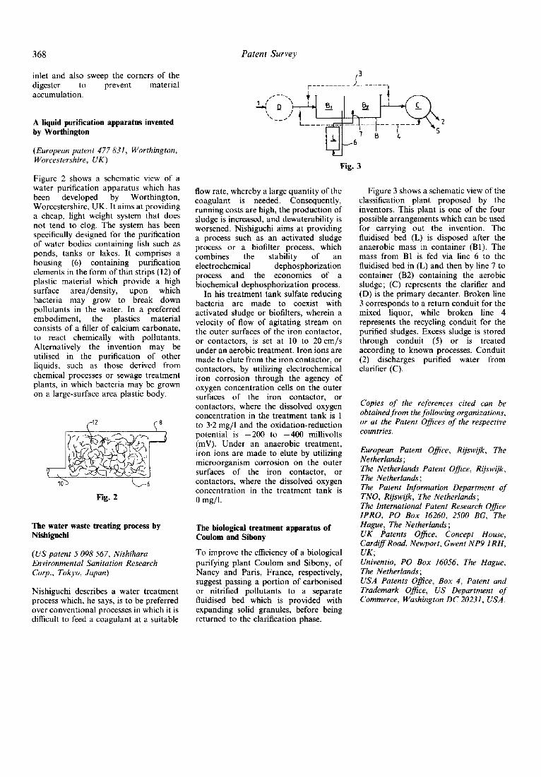
T h e b i o l o g i c a l t r e a t m e n t a p p a r a t u s o f C o u l o m a n d S i b o n y
To improve the efficiency of a biological purifying plant Coulom and Sibony, of Nancy and Paris, France, respectively, suggest passing a portion of carbonised or nitrified pollutants to a separate fluidised bed which is provided with expanding solid granules, before being returned to the clarification phase.
Figure 3 shows a schematic view of the classification plant proposed by the inventors. This plant is one of the four possible arrangements which can be used for carrying out the invention. The fluidised bed (L) is disposed after the anaerobic mass in container (B1). The mass from BI is fed via line 6 to the fluidised bed in (L) and then by line 7 to container (B2) containing the aerobic sludge; (C) represents the clarifier and (D) is the primary decanter. Broken line 3 corresponds to a return conduit for the mixed liquor, while broken line 4 represents the recycling conduit for the purified sludges. Excess sludge is stored through conduit (5) or is treated according to known processes. Conduit (2) discharges purified water from clarifier (C).
C o p i e s o f t h e r e f e r e n c e s c i t e d c a n b e o b t a i n e d f r o m t h e f o l l o w i n g o r g a n i z a t i o n s , o r a t t h e P a t e n t O f f i c e s o f t h e r e s p e c t i v e c o u n t r i e s .
E u r o p e a n P a t e n t O f f i c e , R i j s w i j k , T h e N e t h e r l a n d s ; T h e N e t h e r l a n d s P a t e n t O f f i c e , R i j s w i j k , T h e N e t h e r l a n d s ; T h e P a t e n t I n f o r m a t i o n D e p a r t m e n t o f T N O , R i j s w i j k , T h e N e t h e r l a n d s ; T h e I n t e r n a t i o n a l P a t e n t R e s e a r c h O f f i c e I P R O , P O B o x 1 6 2 6 0 , 2 5 0 0 B G , T h e H a g u e , T h e N e t h e r l a n d s ; U K P a t e n t s O f f i c e , C o n c e p t H o u s e , C a r d i f f R o a d , N e w p o r t , G w e n t N P 9 1 R H , U K ; U n i v e n t i o , P O B o x 1 6 0 5 6 , T h e H a g u e , T h e N e t h e r l a n d s ; U S A P a t e n t s O f f i c e , B o x 4 , P a t e n t a n d T r a d e m a r k O f f i c e , U S D e p a r t m e n t o f C o m m e r c e , W a s h i n g t o n D C 2 0 2 3 1 , U S A .


![[TRUNG TAM TIENG NHAT DEKIRU] Nishiguchi K. - Understanding Basic Japanese Grammar - 2000](https://img.pdfslide.net/doc/110x75/577cc1a71a28aba711939b35/trung-tam-tieng-nhat-dekiru-nishiguchi-k-understanding-basic-japanese.jpg)