Embed Size (px)
Citation preview
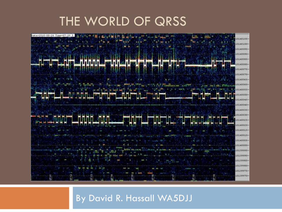
THE WORLD OF QRSS
By David R. Hassall WA5DJJ
What we are doing?
We are transmitting our Amateur Radio Calls using various modulation schemes at very low power to see how far it travels with the existing radio wave propagation.
Most QRSS transmitters are built from scratch or kits
The transmitter power rarely exceeds 1 watt and most run about 200 milliwatts.
Reception of the signals is done with a stable receiver connected to a computer running a spectrum analyzer program.
Who is doing it?
Radio Amateurs from all over the world who enjoy
seeing just how far their tiny signal will travel and
also enjoy studying Radio Wave Propagation.
They come from all walks of life and are innovative
experimenters.
We are loosely banded together through the
internet email reflector run by the KNIGHTS OF THE
QRSS.
How are we doing it?
Building little QRPp transmitters from plans or kits.
Putting them on the air with an available antenna.
Watching for the signal to appear on one of the established QRSS GRABBER stations or wait for an email from someone who copied our signal.
We modify our station’s transmitter or Antenna to see if we can make our signal go farther than we did the last time.
This is not an “instant gratification” form of Amateur Radio operation, In some ways it is like watching Grass grow.
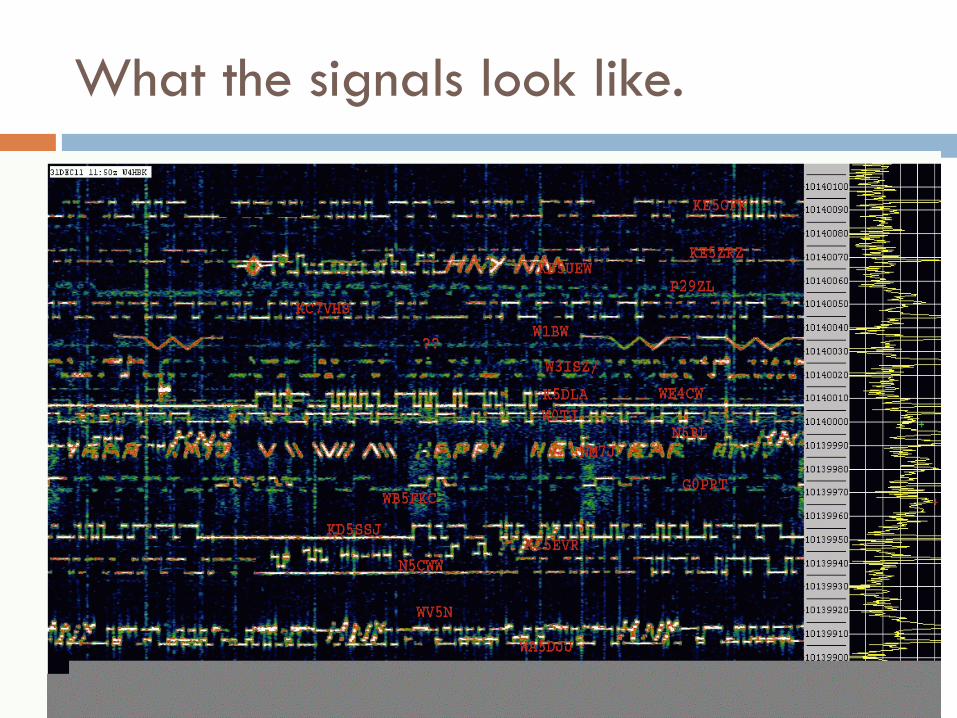
What the signals look like.

QRSS TRANSMITTERS – The model 1
This is a “Homebrewed” 140mW QRSS
transmitter. It was built from Junkbox
parts. It operates on 10,140,050 Hz
(30M Amateur Band). It is easy to
duplicate and was built using the
“Manhattan Style” of construction. The
Keyer IC was purchased from K1EL for
about $6. The Crystal Oscillator is
mounted in a foam box for temperature
stability. It usually maintains it’s
frequency +/- 3 Hz over a 24 hour
period. I call this transmitter my Model 1
and there were about 3 of them
constructed by me. This was my first
QRSS Transmitter.

QRSS Transmitters – The model 2
Taking what I had learned from
the model 1 transmitter… I
created the Model 2. It has a
300mW Power Amplifier stage,
Crystal heater for better
frequency control and a multiple
message K1EL keyer. It’s
frequency stability was +/- 2Hz
over a 24 hour period. It had a
fine frequency control knob so I
could move the frequency slightly
if I was colliding with someone.
The schematics were posted on
my website and there were many
copies of this transmitter built.
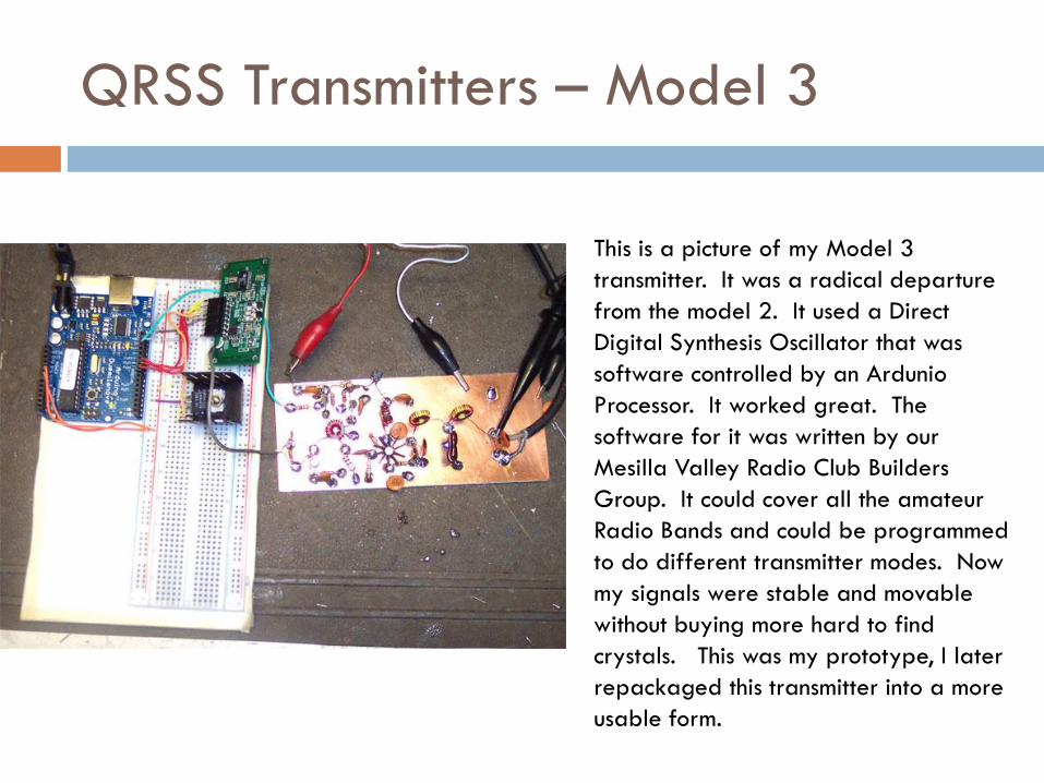
QRSS Transmitters – Model 3
This is a picture of my Model 3
transmitter. It was a radical departure
from the model 2. It used a Direct
Digital Synthesis Oscillator that was
software controlled by an Ardunio
Processor. It worked great. The
software for it was written by our
Mesilla Valley Radio Club Builders
Group. It could cover all the amateur
Radio Bands and could be programmed
to do different transmitter modes. Now
my signals were stable and movable
without buying more hard to find
crystals. This was my prototype, I later
repackaged this transmitter into a more
usable form.
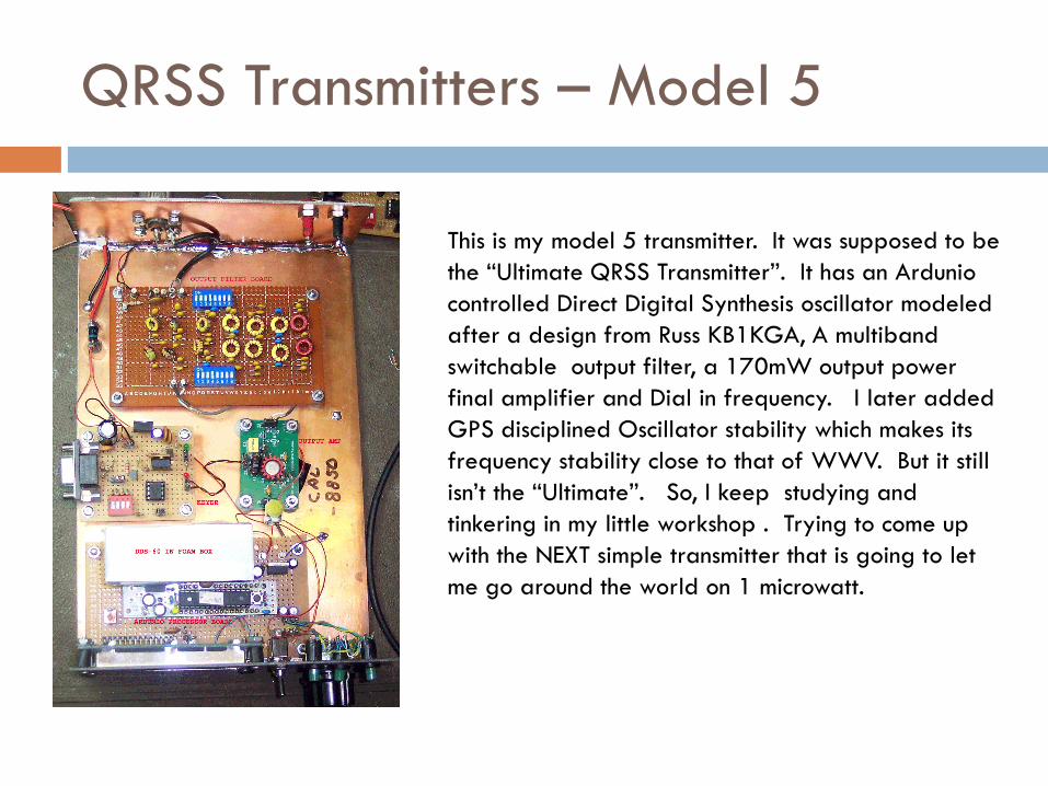
QRSS Transmitters – Model 5
This is my model 5 transmitter. It was supposed to be
the “Ultimate QRSS Transmitter”. It has an Ardunio
controlled Direct Digital Synthesis oscillator modeled
after a design from Russ KB1KGA, A multiband
switchable output filter, a 170mW output power
final amplifier and Dial in frequency. I later added
GPS disciplined Oscillator stability which makes its
frequency stability close to that of WWV. But it still
isn’t the “Ultimate”. So, I keep studying and
tinkering in my little workshop . Trying to come up
with the NEXT simple transmitter that is going to let
me go around the world on 1 microwatt.
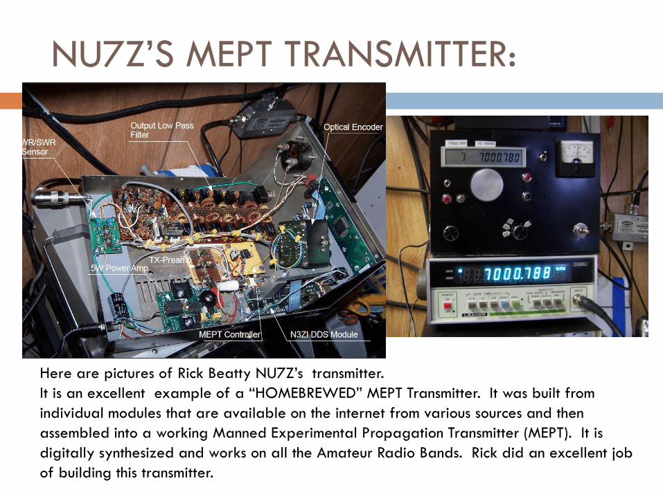
NU7Z’S MEPT TRANSMITTER:
Here are pictures of Rick Beatty NU7Z’s transmitter.
It is an excellent example of a “HOMEBREWED” MEPT Transmitter. It was built from
individual modules that are available on the internet from various sources and then
assembled into a working Manned Experimental Propagation Transmitter (MEPT). It is
digitally synthesized and works on all the Amateur Radio Bands. Rick did an excellent job
of building this transmitter.

QRP labs Transmitter Kit:
This QRPLabs MEPT Transmitter was
designed and produced by Hans Sommers
G0UPL and Steve Farthing G0XAR. This kit
has really increased the number of QRSS
signals on the air. There have been many
sold and a lot of them made it to the
airways. It costs about $17 including
postage from England.
These transmitters come in three models for
80M, 40M and 30M bands.
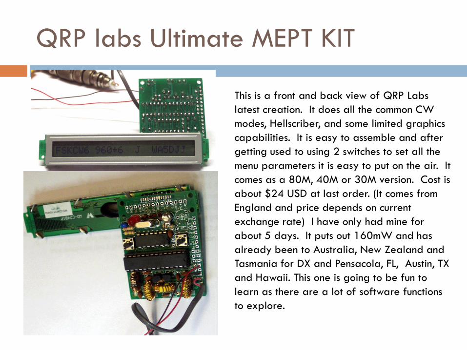
QRP labs Ultimate MEPT KIT
This is a front and back view of QRP Labs
latest creation. It does all the common CW
modes, Hellscriber, and some limited graphics
capabilities. It is easy to assemble and after
getting used to using 2 switches to set all the
menu parameters it is easy to put on the air. It
comes as a 80M, 40M or 30M version. Cost is
about $24 USD at last order. (It comes from
England and price depends on current
exchange rate) I have only had mine for
about 5 days. It puts out 160mW and has
already been to Australia, New Zealand and
Tasmania for DX and Pensacola, FL, Austin, TX
and Hawaii. This one is going to be fun to
learn as there are a lot of software functions
to explore.
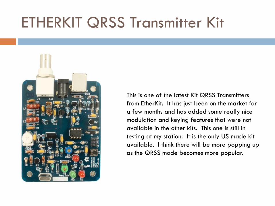
ETHERKIT QRSS Transmitter Kit
This is one of the latest Kit QRSS Transmitters
from EtherKit. It has just been on the market for
a few months and has added some really nice
modulation and keying features that were not
available in the other kits. This one is still in
testing at my station. It is the only US made kit
available. I think there will be more popping up
as the QRSS mode becomes more popular.
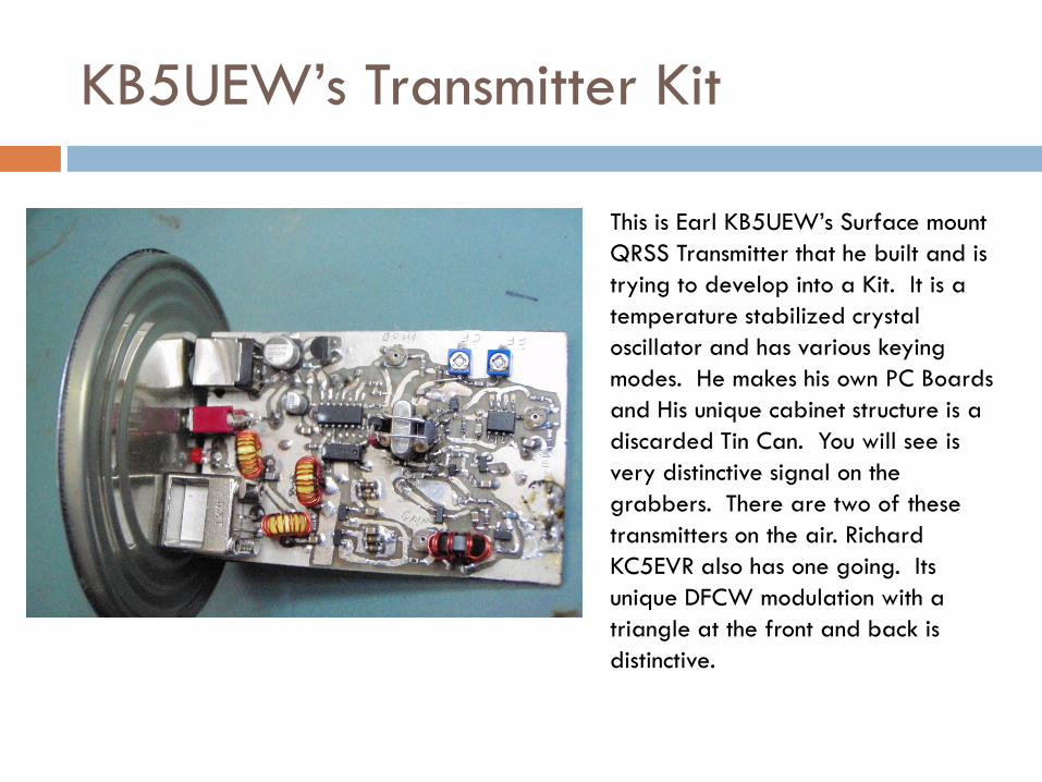
KB5UEW’s Transmitter Kit
This is Earl KB5UEW’s Surface mount
QRSS Transmitter that he built and is
trying to develop into a Kit. It is a
temperature stabilized crystal
oscillator and has various keying
modes. He makes his own PC Boards
and His unique cabinet structure is a
discarded Tin Can. You will see is
very distinctive signal on the
grabbers. There are two of these
transmitters on the air. Richard
KC5EVR also has one going. Its
unique DFCW modulation with a
triangle at the front and back is
distinctive.
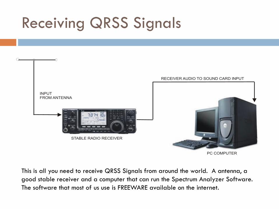
Receiving QRSS Signals
This is all you need to receive QRSS Signals from around the world. A antenna, a
good stable receiver and a computer that can run the Spectrum Analyzer Software.
The software that most of us use is FREEWARE available on the internet.
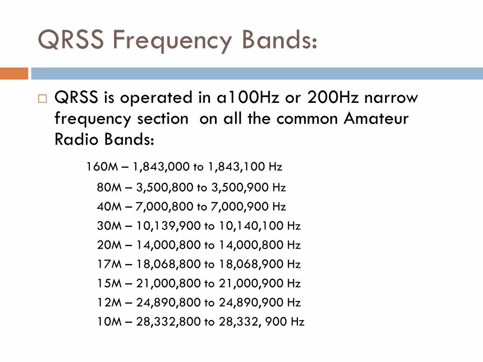
QRSS Frequency Bands:
QRSS is operated in a100Hz or 200Hz narrow frequency section on all the common Amateur Radio Bands:
160M – 1,843,000 to 1,843,100 Hz
80M – 3,500,800 to 3,500,900 Hz
40M – 7,000,800 to 7,000,900 Hz
30M – 10,139,900 to 10,140,100 Hz
20M – 14,000,800 to 14,000,800 Hz
17M – 18,068,800 to 18,068,900 Hz
15M – 21,000,800 to 21,000,900 Hz
12M – 24,890,800 to 24,890,900 Hz
10M – 28,332,800 to 28,332, 900 Hz
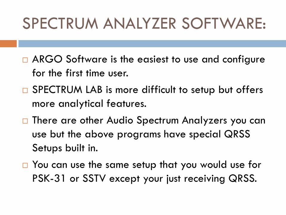
SPECTRUM ANALYZER SOFTWARE:
ARGO Software is the easiest to use and configure
for the first time user.
SPECTRUM LAB is more difficult to setup but offers
more analytical features.
There are other Audio Spectrum Analyzers you can
use but the above programs have special QRSS
Setups built in.
You can use the same setup that you would use for
PSK-31 or SSTV except your just receiving QRSS.

BECOMING A GRABBER:
The only thing you have to add to the basic QRSS
receiving system is a internet connection and a
website to be a Grabber.
We are in dire need of more 24/7 automated
Grabbers on all of the QRSS Frequency bands
around the world on the Internet. If radio wave
propagation could be studied on all of the Amateur
Radio frequencies at the same time, It may give us
valuable clues as to what is REALLY happening.
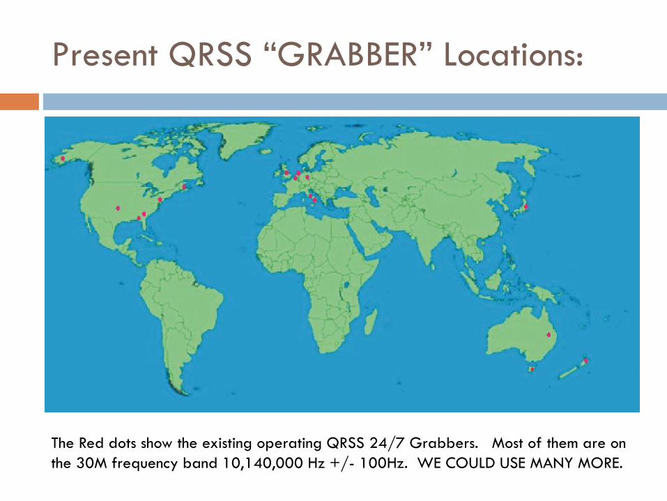
Present QRSS “GRABBER” Locations:
The Red dots show the existing operating QRSS 24/7 Grabbers. Most of them are on
the 30M frequency band 10,140,000 Hz +/- 100Hz. WE COULD USE MANY MORE.
QRSS is a Learning Experience:
Just getting a QRSS transmitter on the air is a real learning experience. Even if you’re an ”Expert”!
Then getting your QRSS transmitter to stay on Frequency is another Lesson.
Antenna building and installation is another learning experience.
Watching what the atmospheric conditions does to your transmitted signal is another learning experience.
There are many things you learned about propagation as an experienced Amateur Radio Operator that will, somehow, turn out to be DIFFERENT, when you start working with QRSS.

Propagation of my Signal:
In this grabber screen shot, My signal is at the bottom of the screen. It should be a clear line with
the up and down shifts. Instead the Ionosphere is modulating my signal so it appears as a broad
line at the top and bottom of the shifts. What is interesting is the two signals at the top of the
screen are hardly being modulated at all. One is coming from Mc Kinney, Texas and the W is from
Concord, MA. Why is this happening?
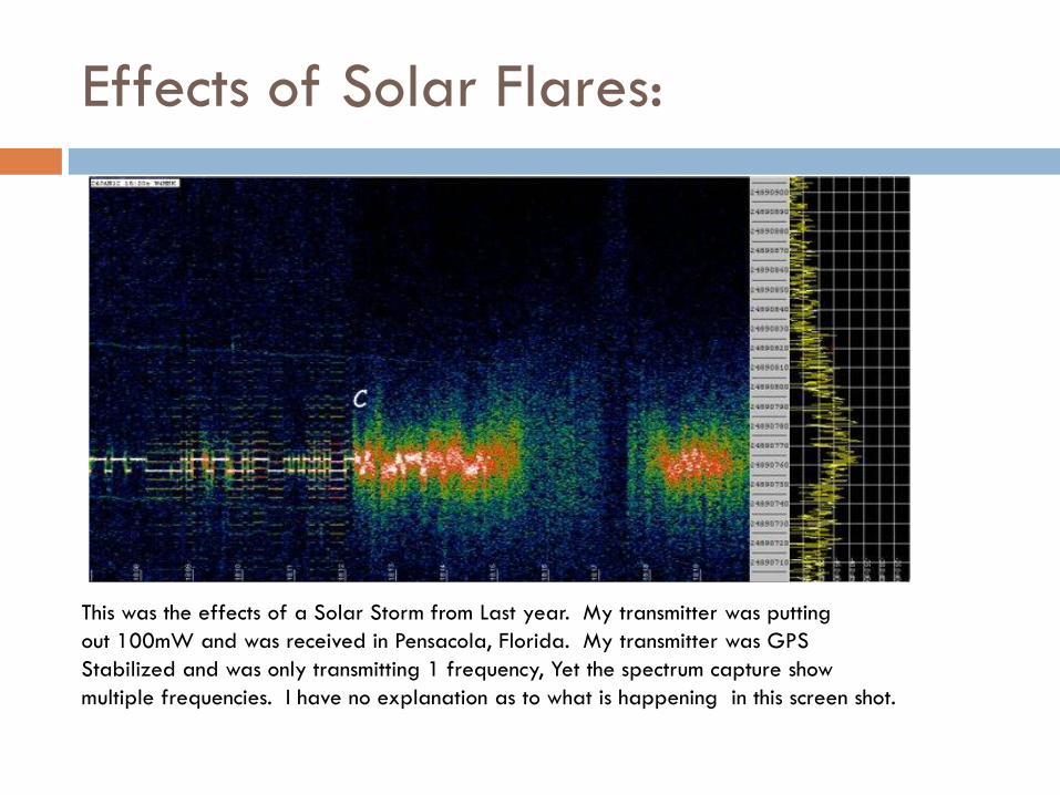
Effects of Solar Flares:
This was the effects of a Solar Storm from Last year. My transmitter was putting
out 100mW and was received in Pensacola, Florida. My transmitter was GPS
Stabilized and was only transmitting 1 frequency, Yet the spectrum capture show
multiple frequencies. I have no explanation as to what is happening in this screen shot.
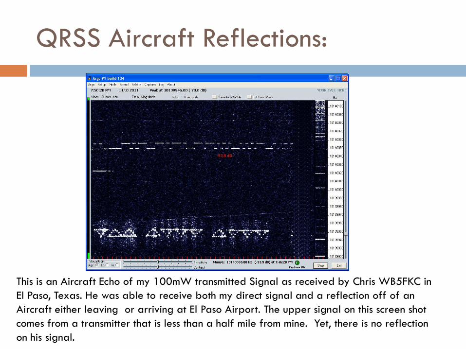
QRSS Aircraft Reflections:
This is an Aircraft Echo of my 100mW transmitted Signal as received by Chris WB5FKC in
El Paso, Texas. He was able to receive both my direct signal and a reflection off of an
Aircraft either leaving or arriving at El Paso Airport. The upper signal on this screen shot
comes from a transmitter that is less than a half mile from mine. Yet, there is no reflection
on his signal.
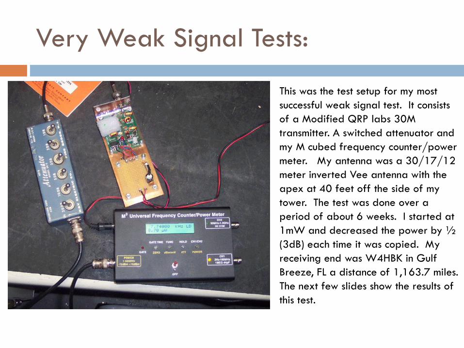
Very Weak Signal Tests:
This was the test setup for my most
successful weak signal test. It consists
of a Modified QRP labs 30M
transmitter. A switched attenuator and
my M cubed frequency counter/power
meter. My antenna was a 30/17/12
meter inverted Vee antenna with the
apex at 40 feet off the side of my
tower. The test was done over a
period of about 6 weeks. I started at
1mW and decreased the power by ½
(3dB) each time it was copied. My
receiving end was W4HBK in Gulf
Breeze, FL a distance of 1,163.7 miles.
The next few slides show the results of
this test.
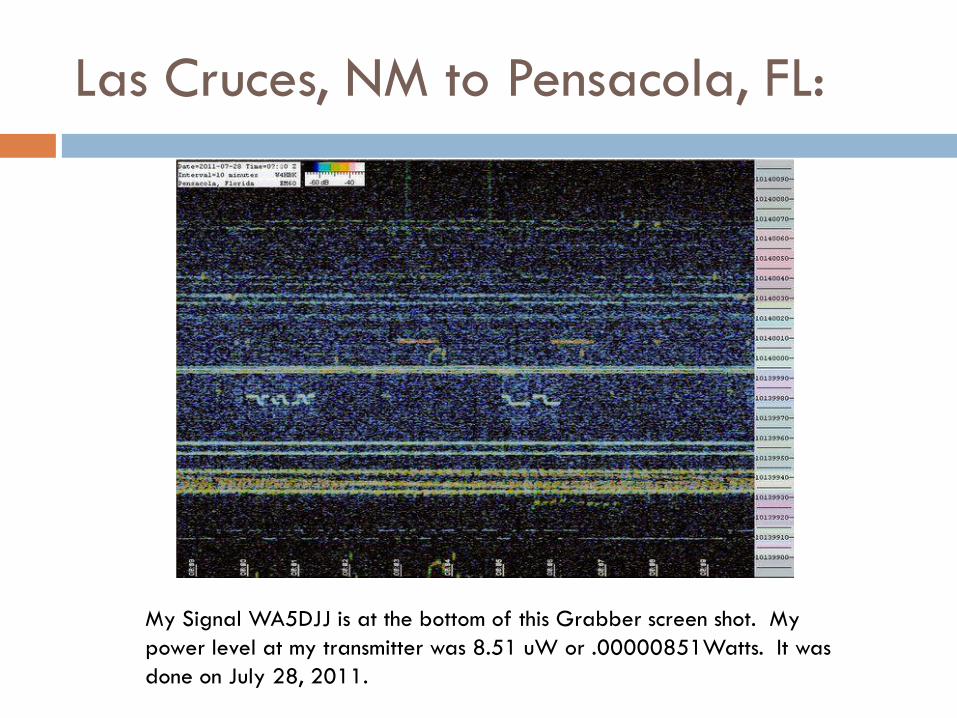
Las Cruces, NM to Pensacola, FL:
My Signal WA5DJJ is at the bottom of this Grabber screen shot. My
power level at my transmitter was 8.51 uW or .00000851Watts. It was
done on July 28, 2011.
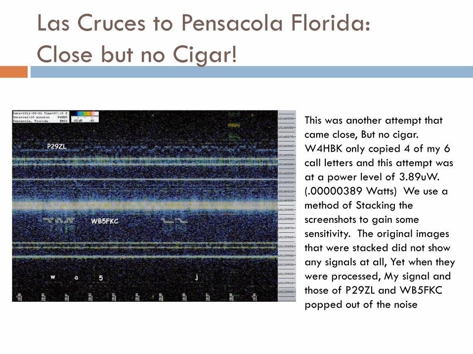
Las Cruces to Pensacola Florida:
Close but no Cigar!
This was another attempt that
came close, But no cigar.
W4HBK only copied 4 of my 6
call letters and this attempt was
at a power level of 3.89uW.
(.00000389 Watts) We use a
method of Stacking the
screenshots to gain some
sensitivity. The original images
that were stacked did not show
any signals at all, Yet when they
were processed, My signal and
those of P29ZL and WB5FKC
popped out of the noise
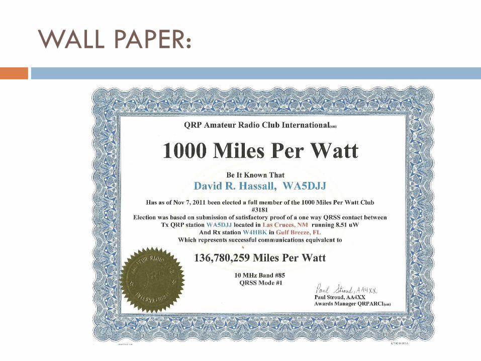
WALL PAPER:
I am always looking for new converts:
I am the “GODFATHER” of the Las Cruces QRSS Mafia.
There are more QRSS Operators within 100 miles of
Las Cruces, New Mexico than anywhere else in the
world. We total 20 at last count. Four years ago
there was only ONE. There is always room for MORE.
If you have grown tired of the YADAA, YADAA, YADAA
of Amateur Radio Operations, Come join us. It will grab
your soul and won’t let go.
To get started, Check out “MY QRSS ADVENTURE” on
the web at: http://www.zianet.com/dhassall/
Questions?
We have some time for Questions and answers.
My website’s “MY QRSS ADVENTURE”
Email me at my QRZ.COM address.
Join the KNIGHTS OF THE QRSS.
SEEK out OTHERS who would be interested in doing
QRSS Operation and learn together.
Blaze a new trail, There is always room for more
innovation.