Embed Size (px)
Citation preview
The Yagi Antenna: History and Design
Presented toSan Antonio Radio Club’s Ham Fiesta 2020
byTom O’Brien, AB5XZ
Which is it?
Yagi-Uda Antenna
A Dragonfly? A Fish bone?
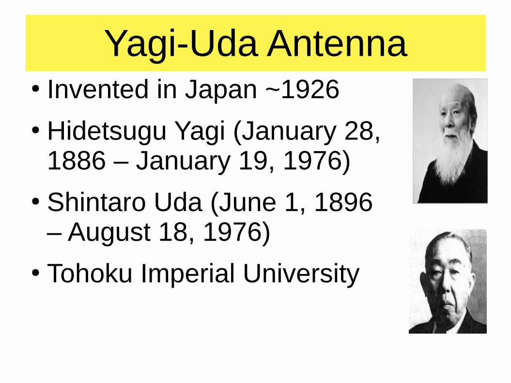
Yagi-Uda Antenna● Invented in Japan ~1926● Hidetsugu Yagi (January 28,
1886 – January 19, 1976)● Shintaro Uda (June 1, 1896
– August 18, 1976)● Tohoku Imperial University
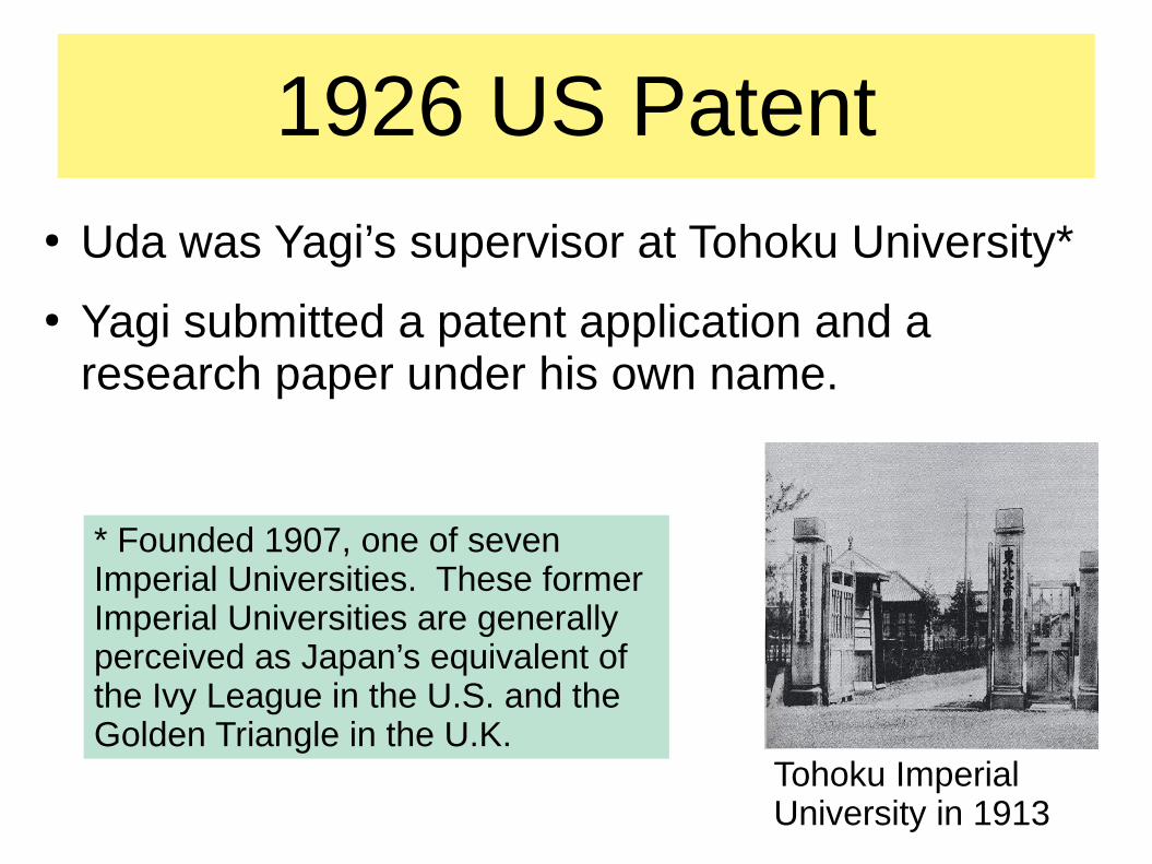
1926 US Patent● Uda was Yagi’s supervisor at Tohoku University*
● Yagi submitted a patent application and a research paper under his own name.
* Founded 1907, one of seven Imperial Universities. These former Imperial Universities are generally perceived as Japan’s equivalent of the Ivy League in the U.S. and the Golden Triangle in the U.K.
Tohoku Imperial University in 1913
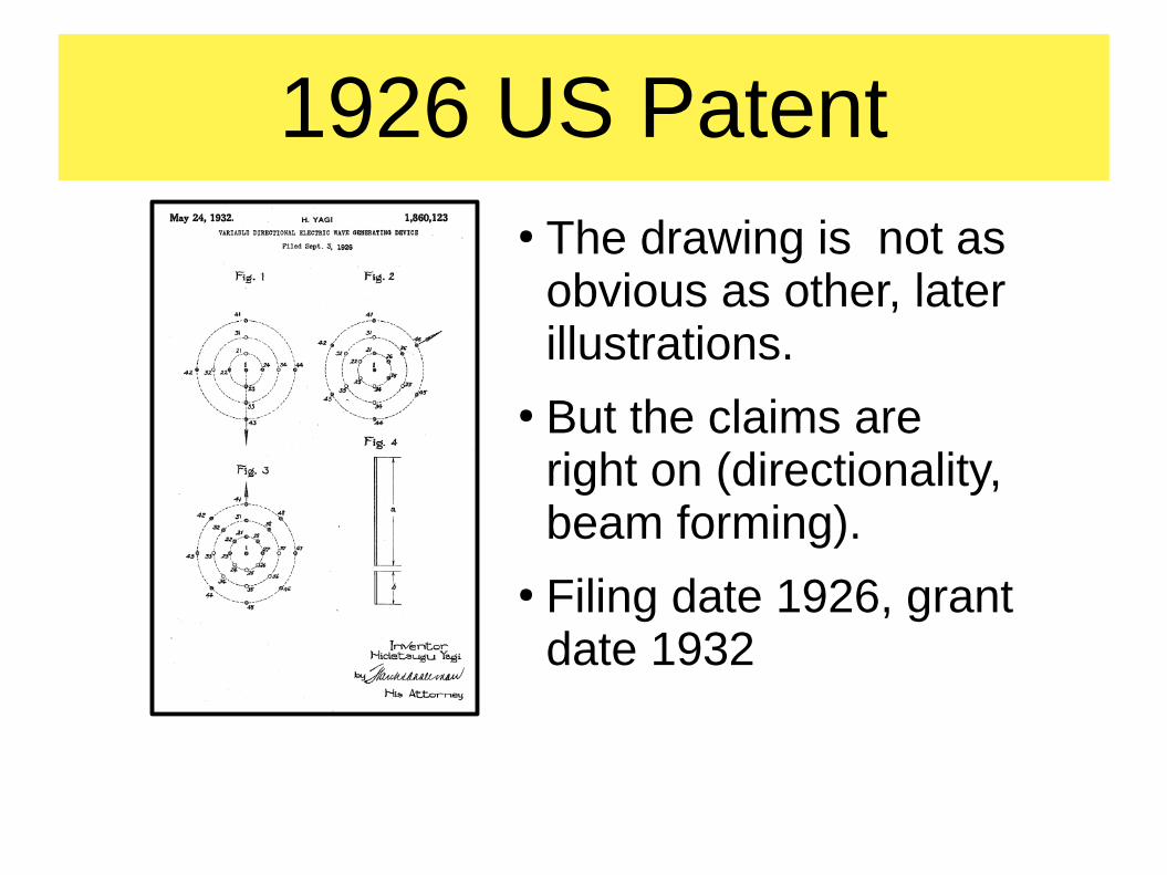
1926 US Patent● The drawing is not as
obvious as other, later illustrations.
● But the claims are right on (directionality, beam forming).
● Filing date 1926, grant date 1932
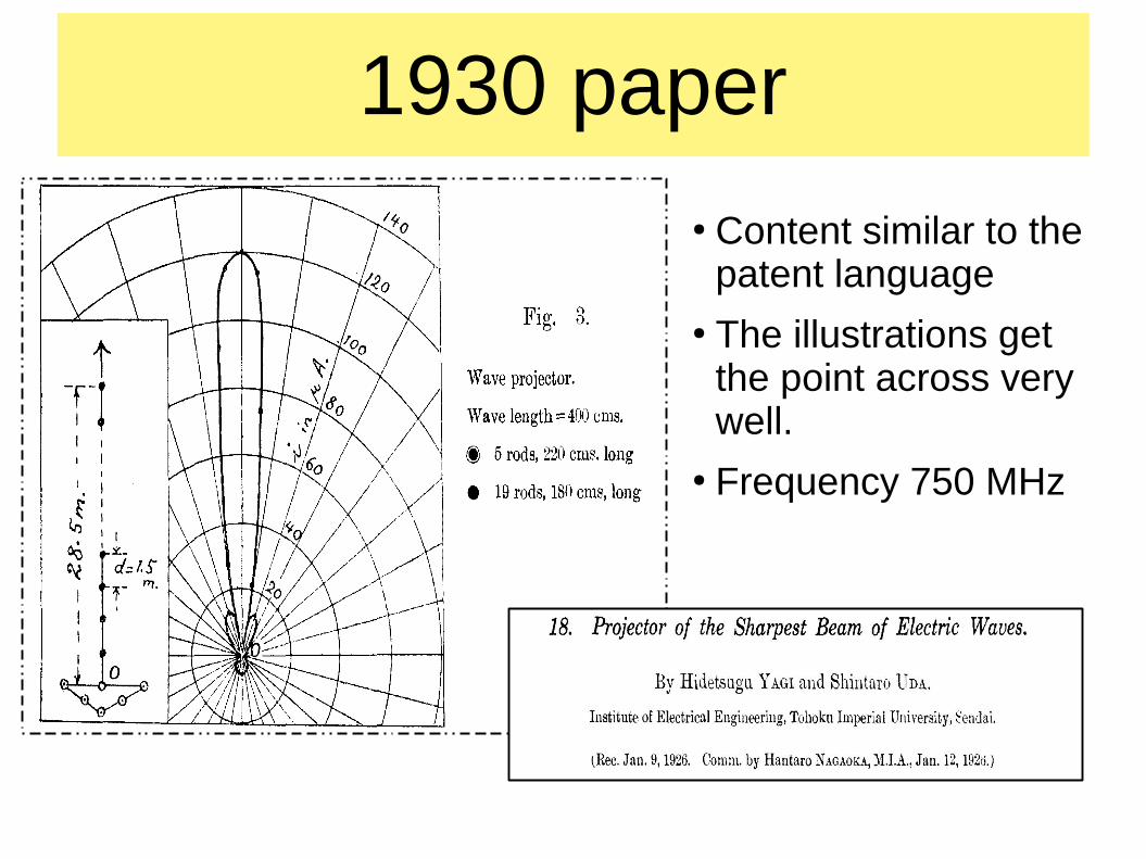
1930 paper
● Content similar to the patent language
● The illustrations get the point across very well.
● Frequency 750 MHz
Allies used the invention in radar
● Germany used the invention to lesser extent.
● Japan made some use of the Yagi antenna in airborne radar, late in World War II.
● One Japanese historian says that the Battle of Midway was an “ambush” partly due to the long-range radar enabled by the Yagi antenna.
● Japanese captured a tech manual on a British searchlight guidance system but didn’t understand the English idiom.
● Germany gave Japan a “Wurzburg” radar as used in Normandy.
● You can see a Wurzburg at National Electronics Museum in MD
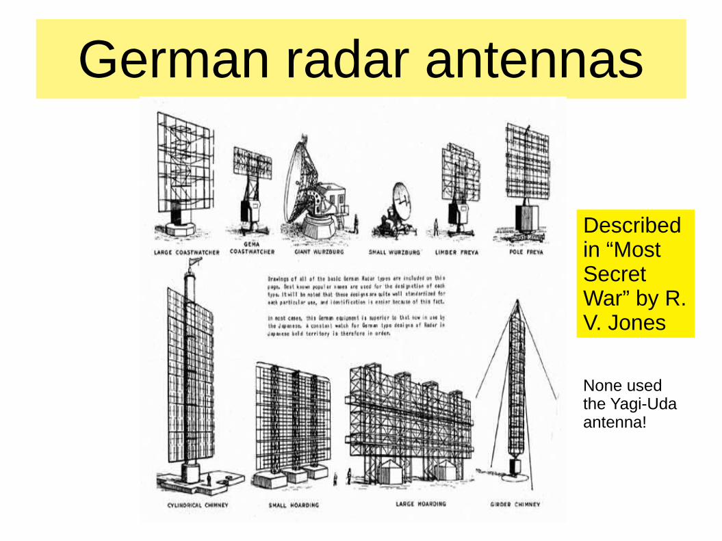
German radar antennas
Described in “Most Secret War” by R. V. Jones
None used the Yagi-Uda antenna!
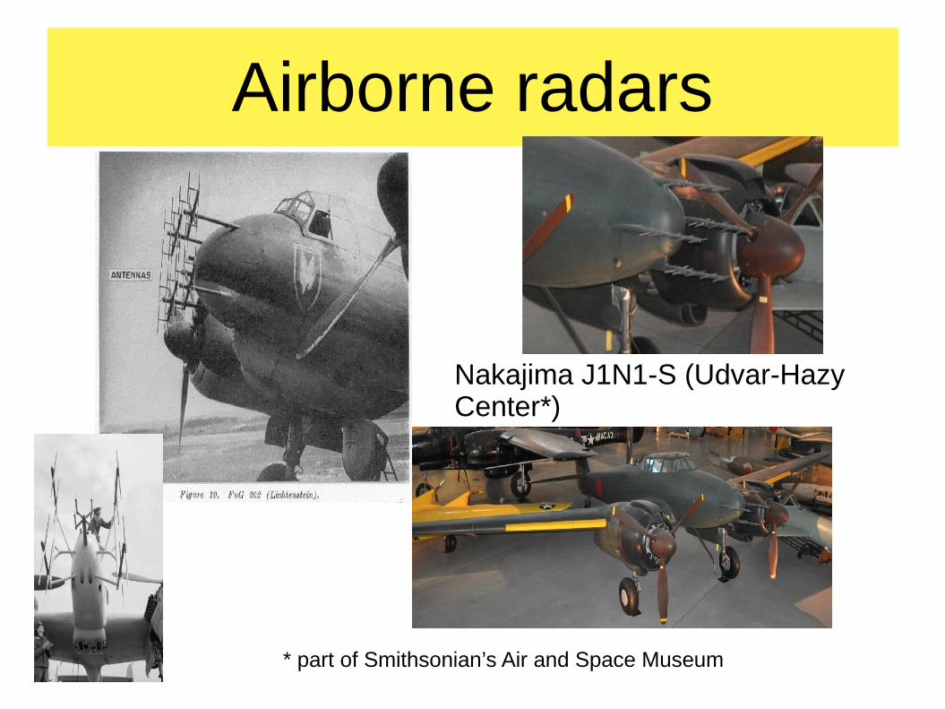
Airborne radars
Nakajima J1N1-S (Udvar-Hazy Center*)
* part of Smithsonian’s Air and Space Museum
Battle of Midway● “It is impossible to plunge into war without a device
which detects a target using electromagnetic waves … the plunge into war without a DENTAN is most thoughtless” – Rear Admiral Yanagimoto (who lost his life at Midway aboard his command, the carrier Soryu)
● “DENTAN” is an abbreviation for a radio locator, i.e., RADAR
● One Japanese author says that Midway was “an ambush” partly because of the longer-range radar of the Allies.
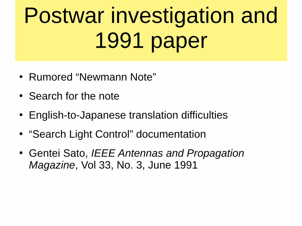
Postwar investigation and 1991 paper
● Rumored “Newmann Note”
● Search for the note
● English-to-Japanese translation difficulties
● “Search Light Control” documentation
● Gentei Sato, IEEE Antennas and Propagation Magazine, Vol 33, No. 3, June 1991
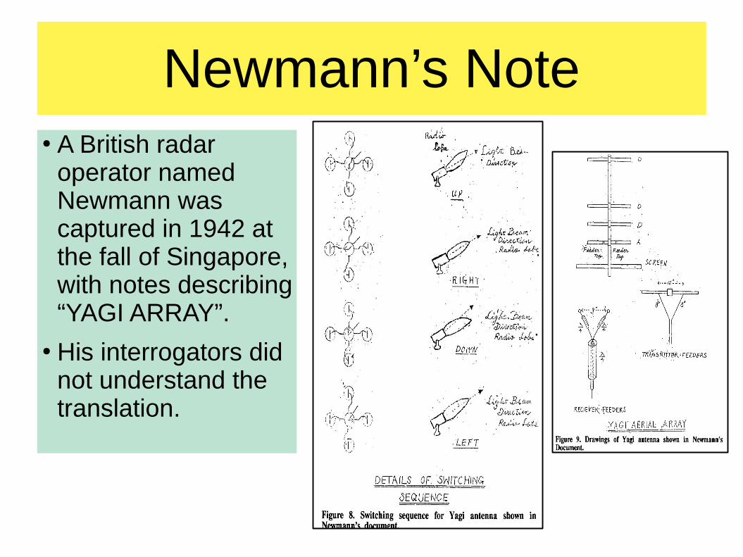
Newmann’s Note● A British radar
operator named Newmann was captured in 1942 at the fall of Singapore, with notes describing “YAGI ARRAY”.
● His interrogators did not understand the translation.
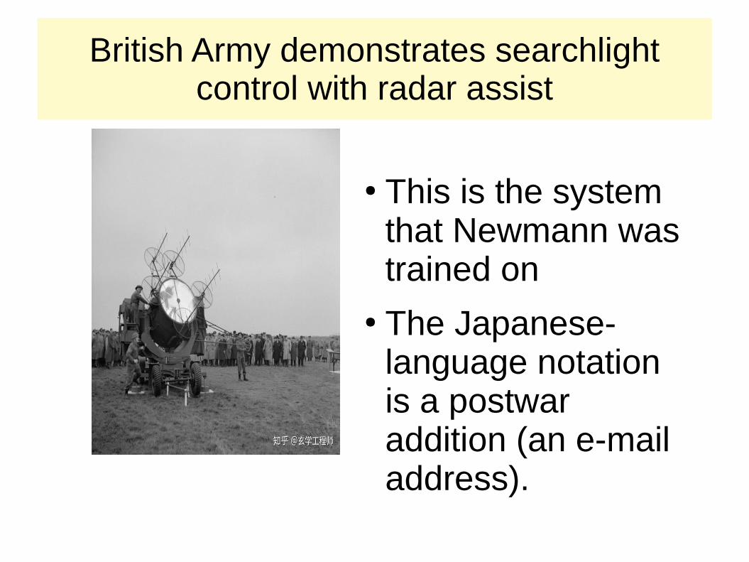
British Army demonstrates searchlight control with radar assist
● This is the system that Newmann was trained on
● The Japanese-language notation is a postwar addition (an e-mail address).
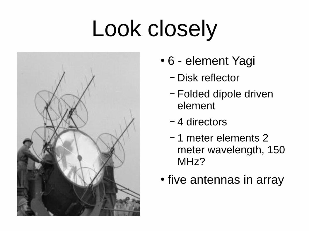
Look closely● 6 - element Yagi
– Disk reflector– Folded dipole driven
element– 4 directors– 1 meter elements 2
meter wavelength, 150 MHz?
● five antennas in array
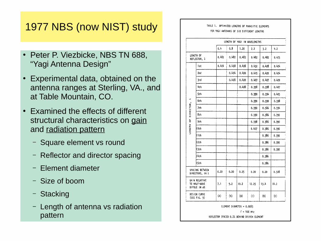
1977 NBS (now NIST) study
● Peter P. Viezbicke, NBS TN 688, “Yagi Antenna Design”
● Experimental data, obtained on the antenna ranges at Sterling, VA., and at Table Mountain, CO.
● Examined the effects of different structural characteristics on gain and radiation pattern
– Square element vs round
– Reflector and director spacing
– Element diameter
– Size of boom
– Stacking
– Length of antenna vs radiation pattern
How does it work?● It is an array antenna● The sizes and positions of the array elements
affect the shape of the radiation pattern
Yagi antenna is a “Parasitic Array”
● One driven element, usually a dipole or a folded dipole
● One or more parasitic elements, usually shaped like dipoles– Reflectors– Directors– Not electrically connected to the driven element– They manipulate the shape of the array’s radiation pattern,
as will any conductor inserted in the antenna’s near field.
Starting assumptions● The plots you will see are modeled
in free space. The real world (which can also be modeled) will always affect the shape of the plot.
● The plots are calculated with various spacing of directors.
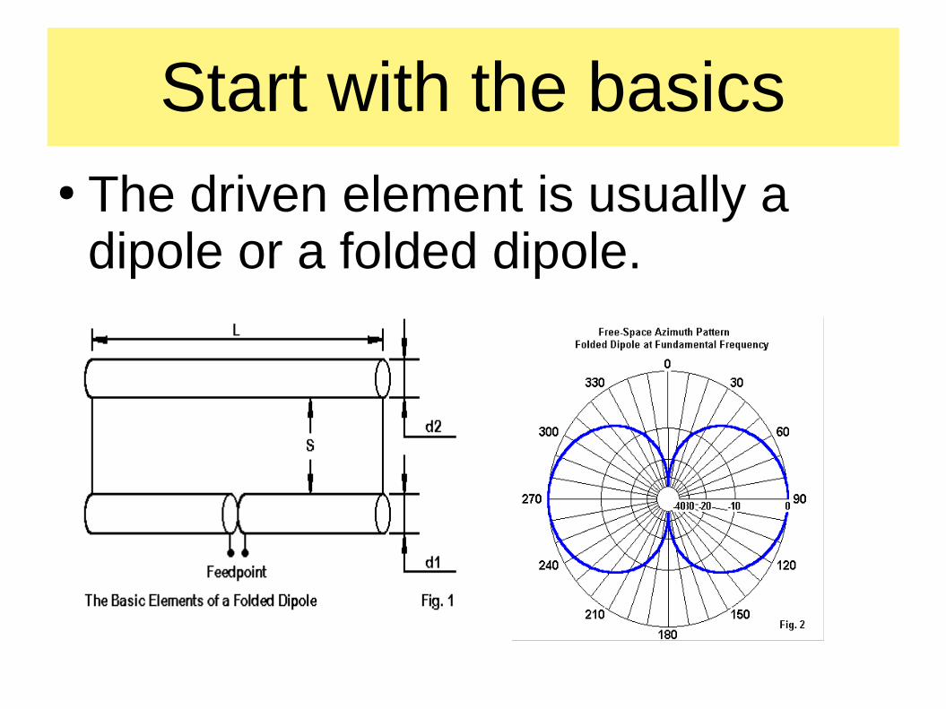
Start with the basics● The driven element is usually a
dipole or a folded dipole.
Reflection● Reflector is about 5% longer than
the driven element, spaced about 1/8 wavelength behind it
● More reflectors can be placed around the driven element, in a cylindrical arrangement
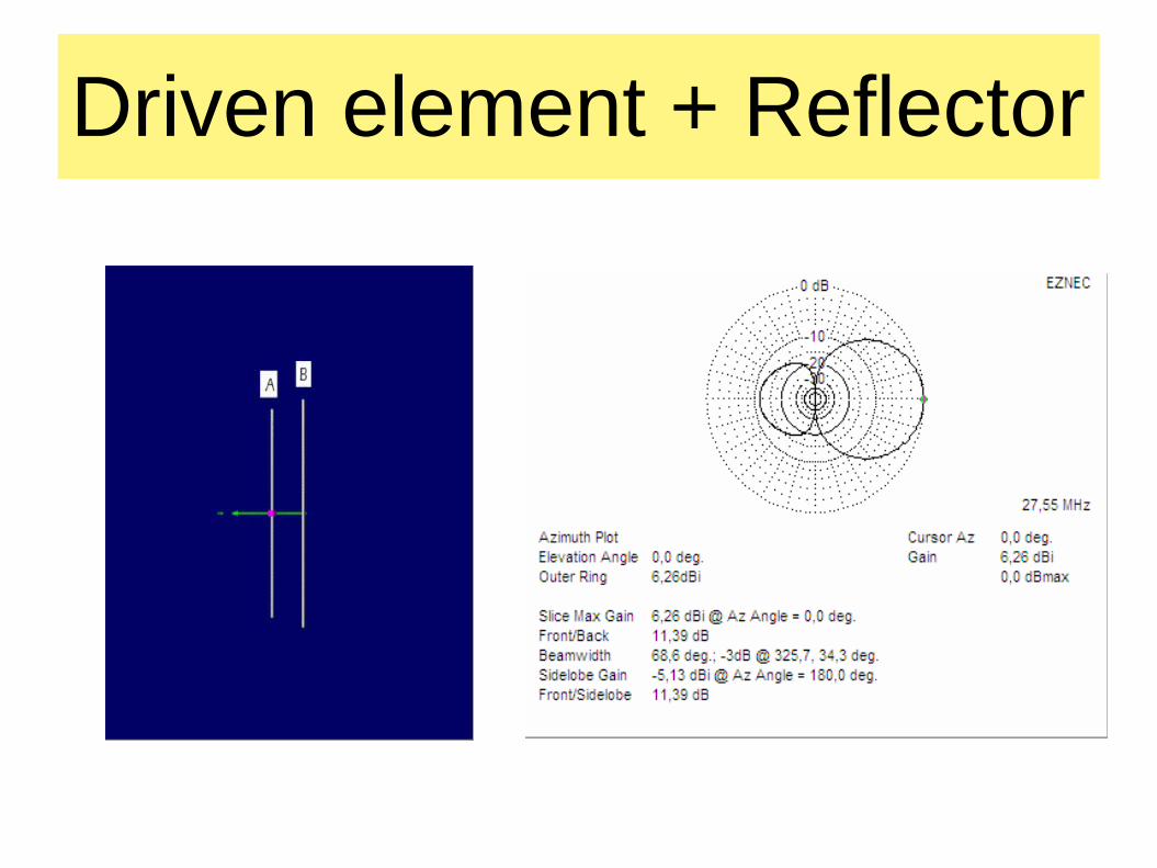
Driven element + Reflector
Directors● The first director is about 5% shorter
than the driven element, and is placed about 1/8 wavelength in front of the driven element.
● Each subsequent director is 5% shorter than the previous one, and is placed about 1/8 wavelength in front.
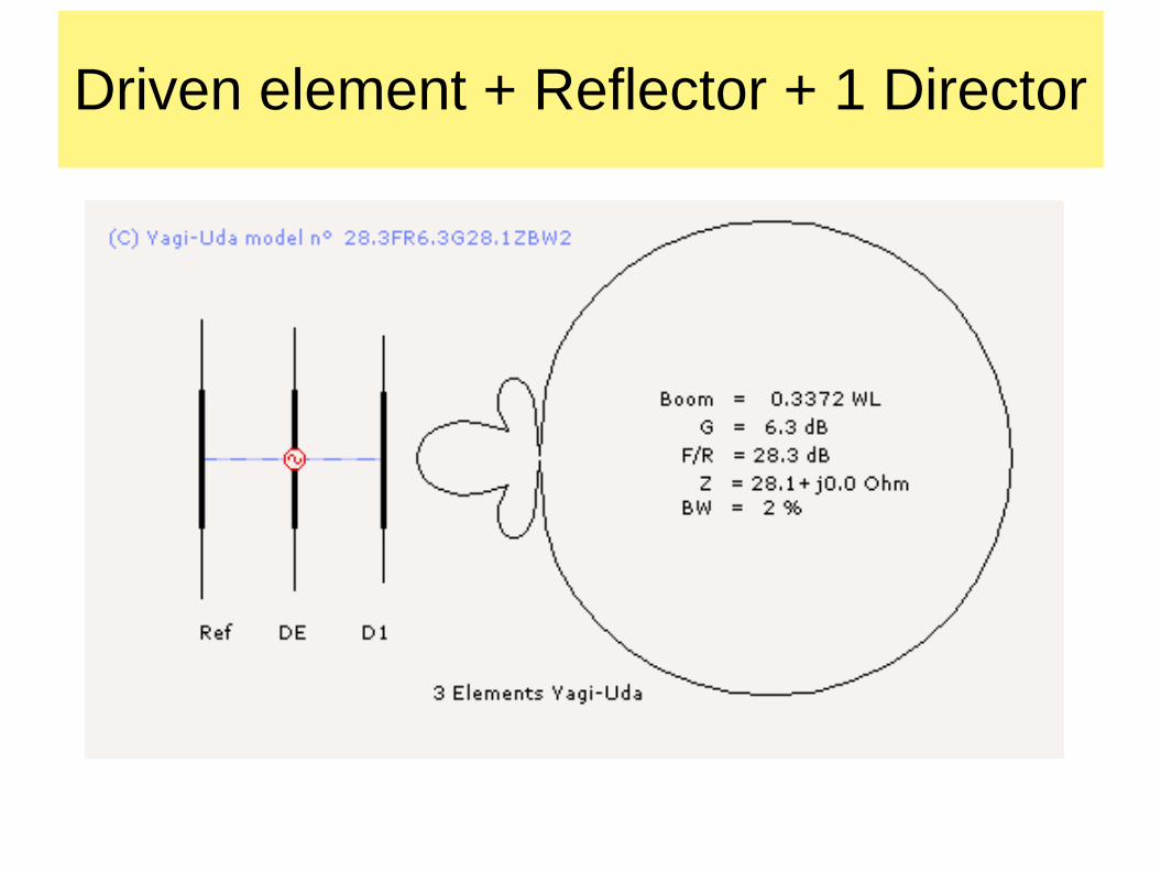
Driven element + Reflector + 1 Director
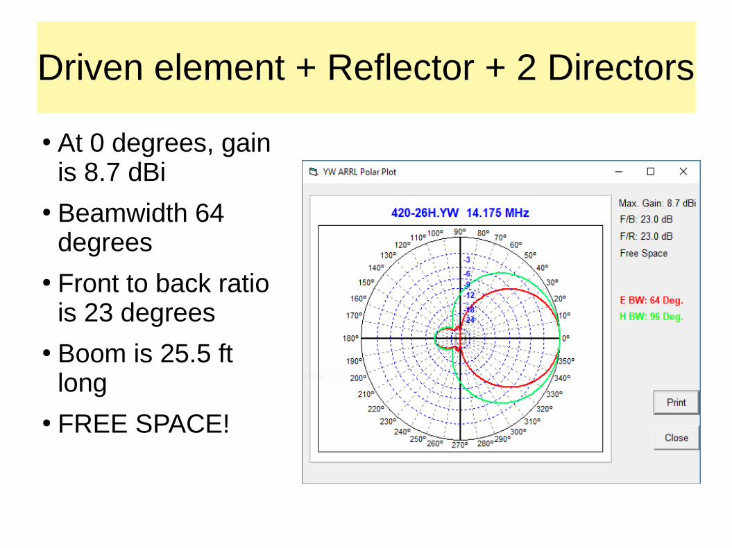
Driven element + Reflector + 2 Directors
● At 0 degrees, gain is 8.7 dBi
● Beamwidth 64 degrees
● Front to back ratio is 23 degrees
● Boom is 25.5 ft long
● FREE SPACE!
Variants
● “Quad” antennas are used at HF, with or without a director.● Elements may be flat metal plates● Most Yagi antennas are designed with impedance
matching devices such as a “gamma match”, a “delta match”, “hairpin”, or other type.
● The boom may be any practical material. Must be rigid.● A “shower curtain” Yagi has been designed and tested
(Leslie Eaton, K5LLE in Houston)
More variants● Stacked arrays of identical Yagi antennas● Dual-band and multi-band Yagi antennas are
available● Crossed Yagi antennas have been used to
generate circular polarization● Elements may be squares, rings, or triangles● Elements may be round or square tubing● Elements may be solid, but must be rigid.
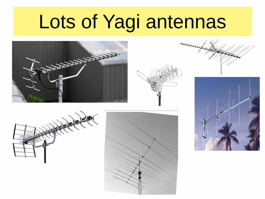
Lots of Yagi antennas
References● Wikipedia articles: “Yagi Antenna”, “Yagi”, “Uda”● ARRL Antenna Book 23rd Edition: “Chapter 11,
The Yagi Antenna”● National Bureau of Standards Tech Note 688:
“Yagi Antenna Design”● IEEE Transactions on Antennas and Propagation,
June 1991 story about the “Newmann Note”● “Yagi Antenna Design” by Dr. James L. Lawson
Comment from NBS● Discussing Yagi’s IRE paper. “Beam transmission of ultra
short waves”, Proc. IRE Vol 16, No. 6, June 1928, pp. 715-741.
● “Prof. Yagi’s remarkable work stimulates thought of a radical order. I venture to suggest that before many years radio operations will generally be considered divided into two classes, broadcasting and directive radio … I have never listened to a paper that I felt so sure was destined to be a classic.” – J. Howard Dellinger, Chief of the Central Radio Propagation Laboratory, in 1928.
● Quoted in NIST “Achievements in Radio” Oct 1986.
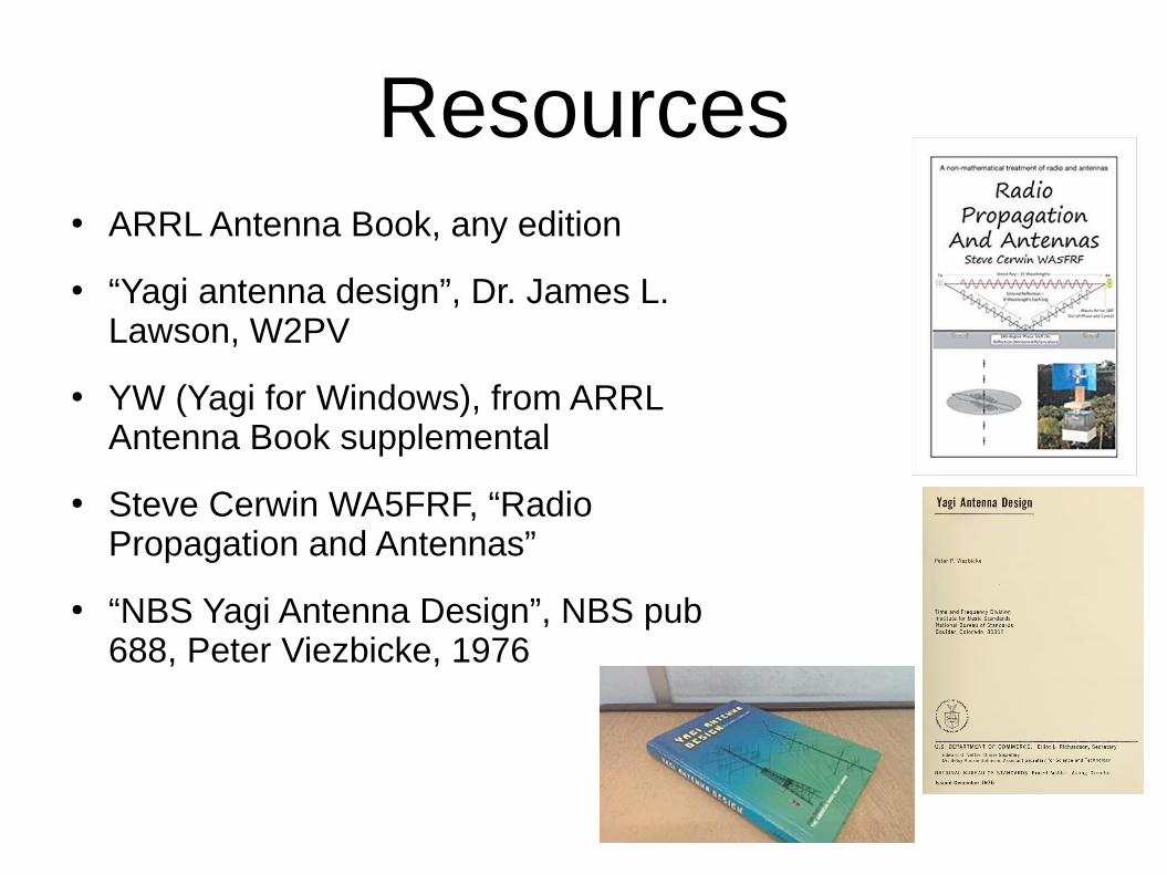
Resources● ARRL Antenna Book, any edition
● “Yagi antenna design”, Dr. James L. Lawson, W2PV
● YW (Yagi for Windows), from ARRL Antenna Book supplemental
● Steve Cerwin WA5FRF, “Radio Propagation and Antennas”
● “NBS Yagi Antenna Design”, NBS pub 688, Peter Viezbicke, 1976
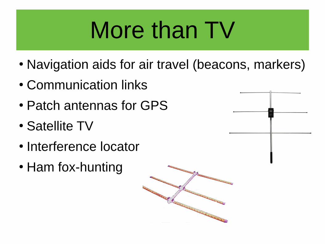
More than TV● Navigation aids for air travel (beacons, markers) ● Communication links● Patch antennas for GPS ● Satellite TV ● Interference locator ● Ham fox-hunting
Disclaimer● This is an informal paper.● I have attempted to give credit where it is
due.● Any errors are probably my fault.● Suggestions and corrections may be
sent to me at this e-mail address: [email protected]
Thank You!● IEEE Lone Star Section● IEEE Life Members Affinity
Group, San Antonio● IEEE Communications
Society● Wikipedia● YouTube● San Antonio Radio Club

Questions?
![Currents on Generalized Yagi StructuresAs recounted by Professor Uda 11,2], the Yagi-Uda antenna was invented in 1926. Further practical and theoretical studies were undertaken, but,](https://img.pdfslide.net/doc/110x75/5e94290536a67159ca4acd82/currents-on-generalized-yagi-structures-as-recounted-by-professor-uda-112-the.jpg)


![Multi-objective Gain-Impedance Optimization of Yagi-Uda ... · better optimization technique for Yagi-Uda antenna designs, in [30]. In this paper, use of BBO, Blended BBO and NSPSO](https://img.pdfslide.net/doc/110x75/60b31a32028c620c9e76b00e/multi-objective-gain-impedance-optimization-of-yagi-uda-better-optimization.jpg)