Embed Size (px)
Citation preview
The experimental determination of temperature andconcentration profiles for a fixed-bed catalytic reactor
Item Type text; Thesis-Reproduction (electronic)
Authors Smith, Edward William, 1942-
Publisher The University of Arizona.
Rights Copyright © is held by the author. Digital access to this materialis made possible by the University Libraries, University of Arizona.Further transmission, reproduction or presentation (such aspublic display or performance) of protected items is prohibitedexcept with permission of the author.
Download date 25/05/2018 01:46:00
Link to Item http://hdl.handle.net/10150/318137
.THE.EXPERIMENTAL DETERMINATION OF TEMPERATURE AND CONCENTRATION
PROFILES FOR A FIXED-BED CATALYTIC REACTOR
by
Edward W i I I I am Srni th
A Thesis Subm itted to th e F a c u lty o f th e
DEPARTMENT OF CHEMICAL ENG INEERING
In P a rt ia I Fu I f i I Iment o f th e Requ i rements For th e Degree o f
' MASTER OF SCIENCE
In th e Graduate GoI Iege
THE UN IVERSITY OF ARIZONA
1969
STATEMENT BY AUTHOR
This t h e s is has-been,submit ted in p a r t i a l f u l f i l l m e n t o f ments f o r an advanced degree a t The U n iv e r s i t y o f Ar izona and is i ted - in the U n iv e r s i t y L ib ra ry t o be made ava i la b Ie t o borrowers ru les o f the L i b r a r y .
B r i e f quo ta t io ns from t h i s t h e s i s are- a l low ab le w i th o u t spec ia l perm iss ion , prov ided t h a t accurate acknowledgment o f source is made. Requests f o r permiss ion f o r extended quo ta t io n from o r rep roduc t ion o f t h i s manuscr ip t in whole o r in p a r t may be granted by the head o f the major department o r the. Dean o f the Graduate Col lege when in h is judgment the proposed use o f the m a te r ia l is in the in te r e s t s o f s c h o la rs h ip . In a l l o th e r ins tances , however, permiss ion must be obta ined from the au tho r .
requ i r e -depos-under
Approval by Thesis D i r e c to r
Th is t h e s i s ' h a s been approved on the date shown be.low:
Edward J . F^efeh P ro fes s o r "o f Chemica iN lng i neer ing
Date
ACKNOWLEDGMENTS
The au thor is indebted t o the e n t i r e f a c u l t y o f the Department
o f Chemical Engineer ing f o r t h e i r encouragement and. a s s is ta n c e , no t on
in p repar ing t h i s t h e s i s but in o th e r academic work as w e l l . Special
a p p re c ia t io n is extended t o Dr. Edward J . Freeh who, as d i r e c t o r o f th
research , gave in v a lu ab le ass is tance in the comple t ion o f t h i s p r o je c t
TABLE OF CONTENTS'
Page
LIST OF ILLUSTRATIONS. . . . . . . . . . . . . . . . . . . . . . . . v
LIST OF. TABLES . . . . , . . . .. . . . . .' . .: .. . . . Vi
ABSTRACT . . . . . . . . . . . . . . . . . .. . . . . . . . . . . . . v i i
INTRODUCTION . .. . . . . . . . . . . . . . . . . . . . . . ... . . . . . I
DESCRIPTION OF EQUIPMENT V . . . . .. . . . . . . . . . 3
Genera I . . . . . . . . ........................... . . . . . . . . . 3
Research Reactor ...................... 5
Ins t rum en ta t ion and Samp I in g .......................... 7
FEED COMPOSITION AND TEMPERATURE FORCING . . . . . ....................... . . 13
Opera t ion , . . . . . . . . . . . . . . . . i . . . . . . . 13
C a l i b r a t i o n . . . . . . . . . . . . 13
EXPERIMENTAL PROCEDURES. . . . . . . . . . . . . . > . . . . . . . 15
ERROR ANALYSIS ....................... . . . . . . . . . . . . . . . . . . , 17
. EXPERIMENTAL RESULTS AND DISCUSSION................... . . . . . . . 19
CONCLUSIONS AMD RECOMMENDATIONS. . . ...................... 30
NOMENCLATURE . . . . . . . . . . . . . . . ... . . . . . . . . . . . 37
APPENDIX A - RAW TEMPERATURE DATA. . . . ’ . . . . . . . . . . 38
APPENDIX-B - TEMPERATURE SUMMARIES , . . . . . . . . . . . . . . . 52
REFERENCES.................. .... . . . . . . . . . . . . . . . . . . . . . . . . . 71
i v
LIST OF ILLUSTRATIONS
Figure
■ u ’
2.
3.
4.
5 . .
6 . -
7.
. 8 ,
9.
10.
I I .
12.
13.
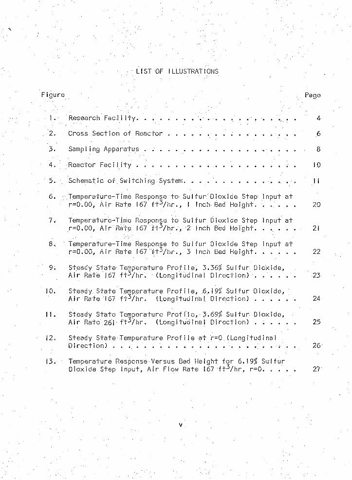
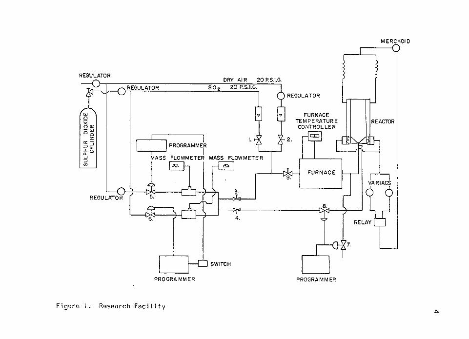
Research Fac i l I t y . . . . . . . . . .. . ., . , . . . ., . .
Cross Sec t ion o f Reactor . . . . . . . . . . . . . . . . .
Sampl ing Apparatus . ............................... .... . . . . . . . . .
•Reactor F a c i l i t y . . . . . . . .. . . . ....................... .
Schematic o f .S w i t c h in g System. ̂ . .
Temperature-Time Response t o Sul f u r D iox ide Step Input a t r = 0 . 00, A i r R a te . 167 f t ^ / h r . , I Inch Bed He igh t . . . . . .
Temperature-Time Response t o S u l f u r D iox ide Step Input a t r=0 .00 . A i r Rate 167 f t - V h r . , 2 Inch Bed He igh t . . . .
Temperature-Time Response t o S u l f u r D iox ide Step Input a t r = 0 . 00, A i r Rate 167 f t ^ / h r . , 3 Inch Bed H e ig h t . . . . . .
Steady State-Temperature Prof i le , 3.36% S u l f u r D iox ide ,A i r Rate 167 f t - V h r . (L o n g i tu d in a l D i r e c t i o n ) . . . . . .
Steady S ta te Temperature P r o f i l e , .6.19% Sul f u r . D i o x i d e ,A i r Rate 167 f t V h r . (Long i tud ina l . D i r e c t i o n ) .................. ....
Steady S ta te Temperature P r o f i l e , 3.69% S u l f u r D iox ide ,A i r Rate 261 • f t V h r . ( L o n g i tu d in a l D i r e c t i o n ) . . . . . .
Steady S ta te Temperature P r o f i l e a t r=0 (Lo n g i tu d in a l D i r e c t i o n ) . . . . . . . . . . . . . . . . . . . V i . . .
Temperature Response Versus Bed He ight f o r 6.19% S u l f u rD iox ide Step I nput, A i r Flow Rate 167 f t V h r , r=0. . . . .
Page
4
.6
8
10
II
20
21
22
23
24
25
26
27
v
LIST OF TABLES
Thermocouple C a l i b r a t i o n , . . . .
E r ro r A n a ly s is . . . . . . . . . . .
Mod i f ied Reynolds Number C a lc u l a t i o n
ABSTRACT
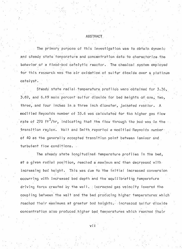
The pr imary purpose o f t h i s i n v e s t i g a t i o n was- t o ob+ain dynamic
and steady s ta te tempera ture and c o n c e n t ra t io n data t o c h a ra c te r i z e the
behav ior o f a f ixed -bed c a t a l y t i c r e a c t o r . The chemical, system employed
f o r t h i s research was the a i r o x i d a t i o n o f s u l f u r d io x id e over a p la t inum
c a t a l y s t .
Steady s t a te rad ia I tempera ture p ro f i I e s were obta ined f o r 3 .36 ,
3 .69 , and 6 .19 mole percent s u l f u r d io x id e f o r bed he igh ts o f one, two,
t h r e e , .and f o u r inches in .a th re e inch d iamete r , ja cke ted r e a c to r . A
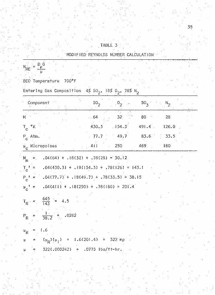
m od i f ied Reynolds number o f 33.6 was c a l c u la te d f o r the h igher gas f lo w
ra te o f 270 f t / h r , i n d i c a t i n g t h a t t h e f lo w through the bed was in th e
t r a n s i t i o n reg io n . Ha l l and Smith repor ted a. m od i f ied Reynolds number
o f 40 as the g e n e ra l l y accepted t r a n s i t i o n p o in t between laminar and
t u r b u le n t f lo w c o n d i t i o n s . .
The steady s t a te lo n g i tu d in a l temperature p r o f i l e s in the bed,
a t a g iven r a d ia l p o s i t i o n , reached a maximum and then decreased w i th
inc reas ing bed h e ig h t . Th is was due to the i n i t i a l increased convers ion
o c c u r r in g w i th increased bed depth and the equ i I i b r a t i n g temperature
d r i v i n g fo rc e c reated by the w a l l . ; increased gas v e l o c i t y lowered the
coup l ing between the wa l l and the bed producing h igher tem pera tu res . which
reached t h e i r maximums a t g re a te r bed h e ig h ts . Increased s u l f u r d io x id e
c o n c e n t ra t io n a lso produced h igher bed temperatures which reached t h e i r
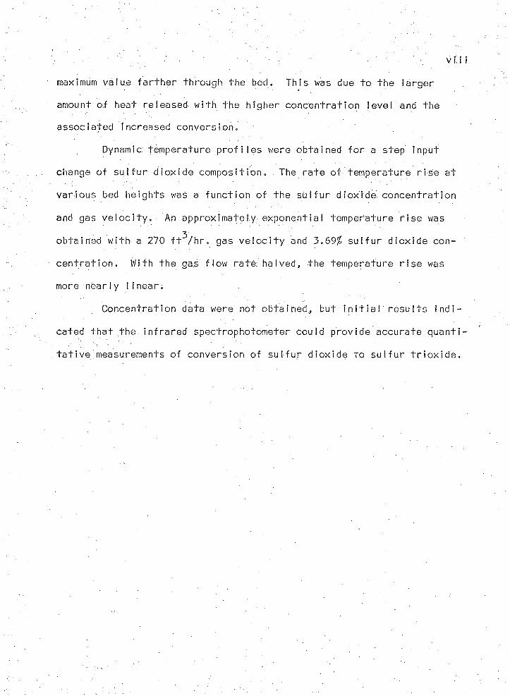
maximum va lue f a r t h e r through the bed. Th is was due t o the la rg e r
amount o f heat released w i th the h ighe r c o n c e n t ra t io n leve l and the
assoc ia ted increased conve rs ion .
Dynamic temperature p r o f i l e s were ob ta ined f o r a step input
change o f s u l f u r d i o x id e c o m p o s i t i o n . The r a te o f tempera ture r i s e a t
v a r iou s bed he igh ts was a fu n c t io n o f the s u l f u r d io x id e c o n c e n t ra t io n
and gas v e l o c i t y . An app rox im a te ly exponent ia l tempera tu re r i s e was"Z
obta ined w i th a 270 f t / h r . gas v e l o c i t y and 3 . 69% s u l f u r d io x id e con
c e n t r a t i o n . With the gas f low r a te ha lved, the tempera ture r i s e was
more nea r ly l i n e a r ;
Concen t ra t ion data were not ob ta ined , bu t i n i t i a l r e s u l t s i n d i
cated t h a t the in f r a r e d spect rophotometer cou ld p rov ide accura te q u a n t i
t a t i v e measurements o f convers ion o f s u l f u r d io x id e t o s u l f u r t r i o x i d e .
INTRODUCTION
This t h e s i s t r e a t s the second phase o f work being undertaken a t
The U n iv e r s i t y o f A r izona t o produce design data f o r the development o f
a mathematical model o f a f i x e d bed c a t a l y t i c , r e a c to r capable o f d e s c r ib
ing both a steady and uns teady -s ta te o p e ra t io n . The chemical system
p re v io u s ly picked f o r the study invo lved the a i r o x i d a t i o n o f s u l f u r
d io x id e over a p la t inum c a t a l y s t ( I ) . The k i n e t i c s o f t h i s exothermic
r e a c t io n are r a th e r we l l known; .however, p resent c o r r e l a t i o n s leave some
th in g t o be des i red from th e s tandpo in t o f t h e i r a p p l i c a b i l i t y over broad
ranges o f temperature and C oncen t ra t ion . Ha l f and Smith (2) have pub
l ished exper imenta l , steady s t a te , temperature and c o n c e n t ra t io n data f o r
the a i r o x i d a t i o n o f s u l f u r d io x id e over a p la t inum c a t a l y s t .
The f i r s t s tud ie s undertaken a t The U n iv e r s i t y o f Ar izona to
produce s u l f u r d i o x id e r e a c to r design data were made by D. A. Pyzel in
1966 as a p a r t o f h is M.S. research ( I ) . Th is work included the i n i t i a l
c o n s t r u c t i o n o f the s u l f u r d io x id e r e a c to r system. Pyzel tes te d two
c o n c e n t ra t io n a n a ly s i s methods, namely the thermal c o n d u c t i v i t y techn ique
and the Orsat a n a ly s i s . The thermal c o n d u c t i v i t y a n a ly s i s apparatus was
a mod if ied gas chromatograph ins trument made by Consol idated E le c t r o
dynamics Company and redesigned by Pyzel t o meet ,the requ irements o f th e
SO^-SO^-ai r system. These m o d i f i c a t i o n s cons is ted p r i m a r i l y o f s t r i c t
temperature c o n t ro l o f the gas sample. The gas sample was maintained
2
above 122°F in o rde r t o p revent p r e c i p i t a t i o n of . the SO^. Mr. P y z e l ' s
r e s u l t s showed t h a t t h i s apparatus d id no t g ive adequate dynamic response
nor cou ld i t d i s t i n g u i s h between SO^ and SO^. The Orsat a n a l y s i s t e c h
nique a l s o proved t o be inadequate due t o the i n a b i l i t y t o o b ta in re p ro
d u c ib le r e s u l t s .
The presen t study was undertaken t o o b ta in both steady and
uns teady -s ta te temperature arid concen t ra t ion , p r o f i l e s across the bed o f
a f ixed -bed c a t a l y t i c r e a c to r . These data we re t to be used f o r f u tu re
comparison w i fh t h a t p red ic te d by a computer s im u la t io n o f the same
re a c t io n system. The t e s t f a c i l i t y f o r t h i s study cons is ted o f a
jacke ted r e a c to r c o n ta in in g a b o i l i n g l i q u i d heated by th re e e l e c t r i c
immersion hea te rs . The c a t a l y s t f o r the o x i d a t io n re a c t io n Consisted
o f small spheres o f alumina w i th a sur face coa t ing o f p la t inum . Radial
temperature p r o f i l e s f o r both s te a d y - s ta te and dynamic c o n d i t i o n s were
determined a t v a r io u s a x ia l p o s i t i o n s in the bed. Concen t ra t ion p ro f i I e s
were t o have been obta ined also'; however, some d i f f i c u l t y was encountered
in p e r f e c t i n g the in f r a re d a n a ly s i s techn ique .
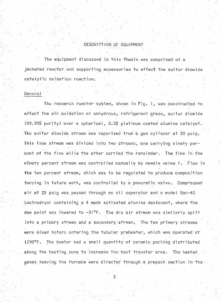
DESCRIPTION OF EQUIPMENT
The equipment discussed in t h i s t h e s i s was comprised o f a
jacke ted r e a c to r and suppor t ing accesso r ies t o e f f e c t the s u l f u r d io x id e
c a t a l y t i c o x id a t io n r e a c t io n .
Genera I " . ' .
The research r e a c to r system, shown in F ig . I , was cons t ruc ted t o
e f f e c t the a i r o x i d a t i o n o f anhyd rous , . r e f r i g e r a n t grade, s u l f u r d io x id e
(99.99% p u r i t y ) over a s p h e r i c a l , 0.5% p la t inum coated alumina c a t a l y s t .
The s u l f u r d io x id e stream was vapor ized from a gas c y l i n d e r a t 20 ps ig .
Th is f lo w stream was d i v id e d in to two streams, one c a r r y i n g n in e ty pe r
cen t o f the f low w h i le the o th e r c a r r i e d the remainder. The f low in the
n in e ty percent stream was c o n t r o l l e d manual ly by needle va lve I . Flow in
the ten percent stream, which was t o be regu la ted t o produce compos i t ion
f o r c i n g in f u t u r e work, was c o n t r o l l e d by a pneumatic Valve.. Compressed
a i r a t 25 ps ig was passed through an o i l separa to r and a model Bac-40:
Lec t rod rye r c o n ta in in g a 4 mesh a c t i v a t e d alumina d e s ic c a n t , where the
dew p o in t was lowered t o - 3 1°F. The dry a i r stream was s i m i l a r l y s p l i t
i n to a pr imary stream and a secondary stream. ■ The two pr imary streams
were mixed before e n te r in g the t u b u la r p rehea te r , which was operated a t
I290°F. The heater had a small q u a n t i t y o f ceramic pack ing d i s t r i b u t e d
along the heat ing zone t o increase th e heat t r a n s f e r a r e a . The heated
gases leav ing the fu rnace were d i re c te d through a prepack s ec t ion in the
3
MERCHOID
— O
REGULATOR
— O - j — ~r~ % — v / — O
DRY AIR 2 0 P.S.I.G.2 0 P.S.I.G.SOREGULATOR
REGULATOR
FURNACET E M P E R A T U R E
CONTROLLERREACTOR
PROGRAMMER
MASS FLOWMETER MASS FLOW METER
F U R N A C E
VAR I AC!
— oREGULATOR
RELAY
L J SWITCH
P R O G R A M M ER PROGRAMMER
igure I . Research F a c i l i t y

' . ■ • . . ' : - ' 5
re a c to r cons i s t i ng o f two i nches o f 3 / 16 i nch a I urni na sphe res .; Th i s r e
g ion served, t o es tab l ish the f low d i s t r i b u t i o n o f .the gas stream through
the packed re a c t io n zone.
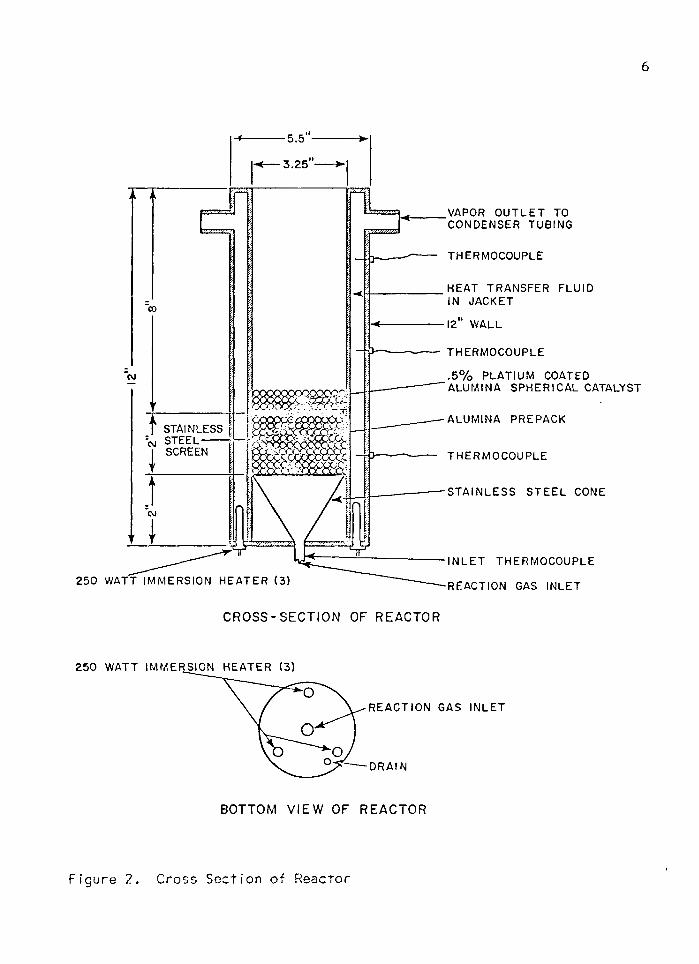
Research Reactor
The r e a c to r , shown in F ig . 2, was f a b r i c a te d from two twe lve inch
lengths o f s t a in l e s s s tee l t u b in g , the in s id e diamete r o f the inner tube
being 3.25 inches, w h i le th e o u ts id e d iamete r o f the o u te r tube was 5.5
inches; These tubes were then capped o f f w i th 1/4 inch p la te s o f s t a i n
less steel . , forming a jacke ted vessel w i th two e x i t p o r t s a t the top f o r
connect ion to condenser tub in g arid f i v e openings a t the bottom f o r the
d r a in , th re e immersion heaters and one f o r the e n te r in g re a c t io n gases.
The e n t i r e vessel was lagged w i th a high temperature i n s u la t i o n . A ven t
va lve , a pressure gauge and a Mercoid sw i tch Were i n s t a l l e d in the con
denser l i n e . A high tempera ture heat t r a n s f e r f l u i d was used in the
j a c k e t o f the r e a c to r . Constant wa l l temperatures were mainta ined by
b o i l i n g the heat t r a n s f e r f l u i d . The f l u i d used was Thermino I FR-0, a
c h l o r i n a te d b ip h e n y l . A t e s t sample o f t h i s f l u i d was bo i led f o r a
per iod o f t im e t o determine what changes might, occur in i t s c h a r a c t e r i s
t i c s . i t was noted t h a t the f l u i d in c o n ta c t w i th the heat ing element ,
where a high heat f l u x e x i s t e d / would begin t o decompose a f t e r being
heated a s ho r t length o f t im e . Even w i th the apparent c a rb o n iz a t io n o f
t h i s f l u i d the wa I I temperature rerna i ned essent i a I I y c o n s ta n t . The
s l i g h t temperature v a r i a t i o n from the top t o the bottom o f the j a c k e t •
was a t t r i b u t e d to the h y d r o s t a t i c head e x i s t i n g in the system. The
6
3 .2 5
VAPOR O U T L E T TO CO N D E N S E R TU B IN G
T H ER M O C O U PLE
HEA T T R A N S F E R F L U ID IN JACKET
12 W ALL
T H E R M O C O U P L E
. 5 % P L A T IU M COATED A L U M IN A S P H E R IC A L CATALYST
A L U M IN A P RE PACKSTAINLESSS TEE L-------SCREEN T H E R M O C O U P L E
S T A IN L E S S S T E E L CONE
N L E T T H E R M O C O U P L E
2 5 0 W ATT IM M E R S IO N H E A T E R (3 ) REACTION GAS IN L E T
C R O S S -S E C T IO N OF REACTOR
IM M E R S IO N H E A T E R (3 )
R E A C T IO N GAS IN L E T
D R A IN
BOTTOM V I E W OF REACTOR
F ig u re 2 . C ross S e c tio n o f R eac to r
■ • ■ ■ • ■ ■ ■ 7
pressure above the heat t r a n s f e r f l u i d was mainta ined by employing a
Mercoid sw i tch c o n t r o l l e r . Once the p rese t pressure was reached, the
c o n t r o l l e r would energ ize a r e la y which shut o f f the immersion hea te rs . .
The th re e 250 w a t t immersion heaters were se t a t the des i red level w i th
a v a r i a b l e t ra n s fo rm e r operated a t n in e ty percen t o f i t s maximum o u tp u t .
Th is amount o f heat al lowed the system t o reach i t s s t e a d y -s ta te va lue
in a minimum amount o f t im e w i th o u t app ly ing an excess ive heat f l u x t o
the heat t r a n s f e r f l u i d . I f the pressure in the system dropped below
the se t p o in t , the Merco id sw i tch would energ ize the heaters' . The m in i
mum d i f f e r e n t i a l on the Mercoid c o n t r o l l e r was two ounces o f pressure,
which provided the c a p a b i l i t y o f sw i tc h in g when the tempera ture changed
less than I°F.
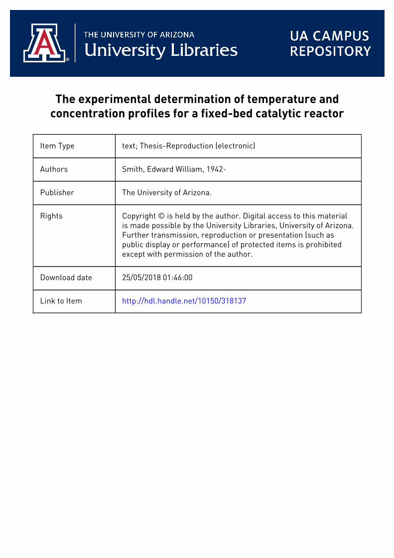
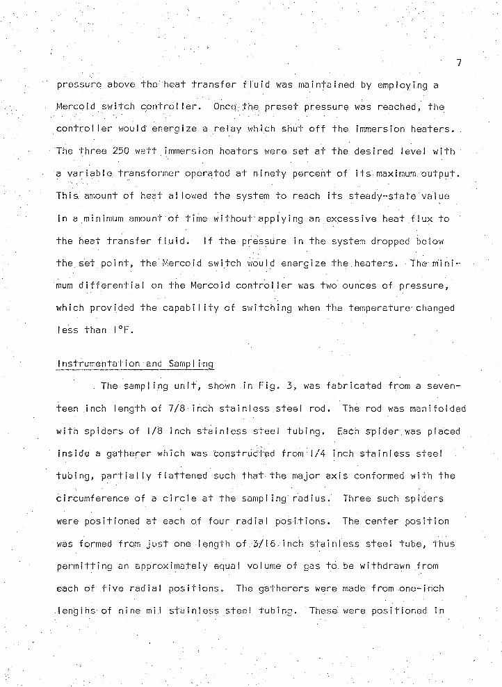
I ns t rumeh ta t ion and Samp I i ng
. The sampl ing u n i t , shown in F ig . 3, was f a b r i c a te d from a seven
teen inch length o f 7 /8 inch s t a i n l e s s s tee l rod. The rod was manifolded
w i th sp ide rs o f 1/8 inch s t a i n l e s s s tee l t u b in g . Each sp ider .was placed
in s ide a g a the re r which was cons t ruc ted from 1/4 'inch s t a i n l e s s s tee l
t u b in g , p a r t i a l l y f l a t t e n e d such t h a t the major ax is conformed w i th the
c i rcumference o f a c i r c l e a t the sampl ing ra d iu s . Three such sp ide rs
were pos i t ione d a t each o f f o u r r a d ia l p o s i t i o n s . The c en te r p o s i t i o n
was formed from j u s t one length o f 3/16 inch sta in I ess s tee l tube , thus
p e r m i t t i n g an approx im ate ly equal volume o f gas t o be wi thdrawn from
each o f f i v e ra d ia l p o s i t i o n s . The ga the re rs were made from one- inch
lengths o f n ine mi l s t a in l e s s s te e l t u b in g . These were pos i t ione d in
8
SAE 7 / 8 " T H R E A D E D ROD
T H E R M O C O U P L E
L E A D S
GASPORTE X IT
P O S IT IO N E R 1 / 8 " S T A IN L E S S S T E E L M A N IF O L D IN G TU B ES
POSITIONER AND R E T A IN E R
C R O S S - S E C T I O N OF SAMPL ING APPARATUS
X / - C E R A M I C F E R R U L E
‘ L- - : f— C E R A M IC C E M E N T
H E R M O C O U P L E
■P O S IT IO N E R AND R E TA IN ER
E E L G A T H E R E R
T H E R M O C O U P L E IN ST A L L A T IO N OF G A T H E R E R
B OTTOM V I E W OF GATHERERS, S M A L L DOTS I N D I C A T E
T H E R M O C O U P L E LOCATION
F ig u re 3 . Sam pling A ppa ra tus
the bed by a t h i n piece o f s t a in l e s s s tee l t u b in g . Three lengths o f 1/16
inch s tee l rod were f i x e d r a d i a l l y t o the m a n i fo ld in g rod t o p o s i t i o n the
u n i t in the bed. Each ga the re r was f i t t e d w i th a small ceramic f e r r u l e
in which a thermocouple was imbedded t o in s u la te i t f rom the ga th e re r .
The thermocouple was pos i t ione d 1/8 inch from the bottom o f the ga th e re r
and was held in t h e f e r r u l e w i th ceramic cement. The thermocouples were
made by he I i - a r c weld ing tw is te d p a i r s o f 30 gauge i ron -cons tan tan w i re .
The leads o f the thermocouples were p ro tec ted w i th a s h ie ld o f asbestos
and a n .o v e r a l l cover o f g lass bra i d. From the m a n i fo ld in g tube f i v e
s p i r a l . lengths o f t ub in g extended from each o f f i v e headers as i l l u s t r a t e d
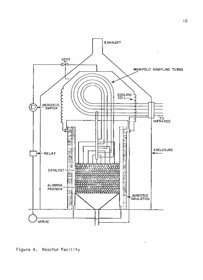
in F ig . 4. Th is a l lowed the u n i t t o be. moved in a v e r t i c a l manner w i th
l i t t l e d i f f i c u l t y . These f i v e lengths o f t u b in g were a t tached t o a
bulkhead where they could e a s i l y be removed. The opp os i te s ide o f the
bulkhead had a panel o f s i x so leno id va lues t h a t were programmed by a
D ig i t e c system to s e q u e n t i a l l y Sample r e a c t io n gases a t each o f the f i v e
r a d ia l p o s i t i o n s in a d d i t i o n t o the re a c to r i n l e t stream. The schematic
f o r t h i s system is shown in F ig . 5.
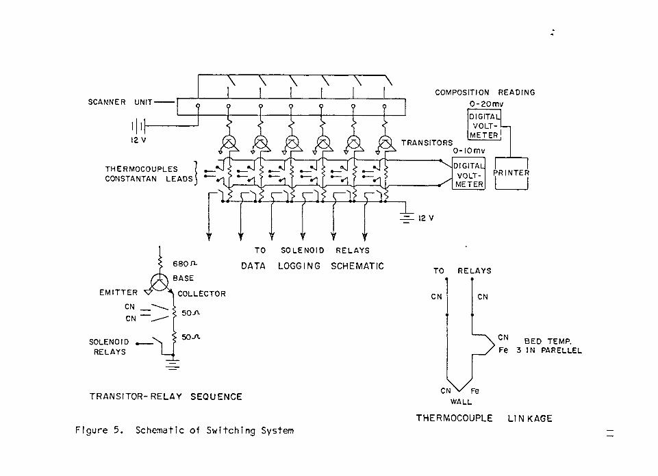
The thermocouple leads were connected t o the sw i tc h in g system
through a pheno l ic c i r c u i t board located beneath the sampl ing so leno id
va lues . The wa l l thermocouple was s e q u e n t i a l l y switched t o be in s e r ie s
w i th a p a r a l l e l hook-up o f the th re e thermocouples located a t each o f
the f i v e ra d ia l p o s i t i o n s as shewn in F ig . 5. Th is was done t o e f f e c t
d . c . suppress ion and a l l o w the m i l l i v o l t readings t o be recorded on the
(0 m i l l i v o l t v o l tm e te r in the data logging system. From the c i r c u i t .
10
E X H A U S T
MANIFOLD SAMPLING TUBES
TO INFRARED
VENT
▻R]
COOLING COIL
MERCHOIDSWITCH
R E L A Y
CATALYST
ALUMINAPREPACK
ASBESTOSINSULATION
ENCLOSURE
VARIAC
F ig u re 4 . R eac to r F a c i l i t y
COMPOSITION R E A D IN G
0 - 2 0 mvSCANNER UNIT
2 V T R A N S IT O R SO - I O m v
T H E R M O C O U P L E S CONSTANTAN L E A D S
P R IN T E R
12 V
DIGITALV O L T
M E T E R
DIGITALV O L T M E T E R
6 8 0 n.
E M I T T E R C O LLEC TO R
50-fV
TO
DATA
S O L E N O ID
LOGGING
R E L A Y S
SCHEMATIC TO R E L A Y S
CN
SOLENOIDR ELA YS
T R A N S IT O R -R E L A Y SEQUENCE
Figure 5. Schematic of Switching System
CN
CN B E D TEM P.Fe 3 IN PAR ELLEL3
Cn\ / - eWALL
THERMOCOUPLE L IN KAGE
- . ; . , ... 12
board two constantan leads f o r each thermocouple were fed t o the s w i t c h
ing u n i t . Th is was necessary t o p reven t a d d i t i o n a l thermocouples from
being placed in s e r ie s w i th the e x i s t i n g arrangement. In o th e r words,
s inee the two Ieads were s i m i l a r any a d d i t i o n a I couples t h a t might e x i s t
due t o d i s s i m i l a r meta ls a t the con tac ts would be cance l led because a l l
elements were e s s e n t i a l l y a t the same tempera tu re . A l l thermocouples
were c a l i b r a t e d a t the b o i l i n g p o in t o f Therrni no I FR-0. See Table I .
As the scanner (see F ig . 5) in the s w i tch ing u n i t se lec ted a
channel , the a p p ro p r ia te t r a n s i s t o r energ ized a l lo w in g a twe lve v o l t
power supp ly t o c lose two re la y s , one p e r m i t t i n g a tempera ture s igna l t o
be recorded, the o th e r a l lo w in g the cor respond ing compos i t ion reading t o
be recorded. In p a r a l l e l w i th t h i s o p e ra t io n the s w i tc h in g system
energ ized a p a r t i c u l a r so leno id va lve thus p e r m i t t i n g gas t o f low from
the selected, sampl ing l i n e t o the Perki n-Elmer model- 137 in f r a r e d s p e c - '
t ro p h o to m e te r . The sample stream t o be analyzed was switched one
sampl ing i n t e r v a l ahead o f the t im e the a n a ly s i s was t o be re a d . Th is
prov ided t ime f o r the t r a n s p o r t lag, sample c e l l f l u s h i n g and s e t t l i n g
o f the ins t rum en t .
FEED COMPOSITION AND TEMPERATURE FORCING
Feed compos i t ion and tempera ture f o r c i n g can be accompl ished
w i th the system shown in F ig . I .
Operat ion
Approx im ate ly n in e ty percen t o f the re a c ta n t feed w i l l be metered
by ro tameters , w h i le the remaining ten percen t w i l l be c o n t r o l l e d and
metered, by the a d d i t i o n a l u n i t s shown in F ig . 1. To e f f e c t feed composi
t i o n f o r c i n g o f the r e a c to r , the ten percen t stream w i l l be va r ied in
com pos i t ion . Dur ing t h i s process va lve 4 w i l l be c losed and va lves I and
2 w i f i determine the f lo w through the ro tamete rs . The movement o f pneu
m at ic va lves 5 and 6 w i l l be programmed f o r th re e fu rnace i n l e t pressures
using Hast i ngs-Rayd i s t mass f low meters . While f o r c i n g these two second
ary streams, a c ons tan t r e a c to r i n l e t pressure w i l l be maintained to a l l o w
cons tan t molar f low through the r e a c to r .
C a l i b r a t i o n
For a g iven r e a c to r i n l e t p ressure , the pressure on the pneumatic
va lves w i l l be va r ied and recorded along w i th the correspond ing mass
f lows.. With t h i s in fo rm a t ion and a graph o f c o n t ro l card rad ius versus
o u tp u t pressure f o r one programmer, a c o n t r o l card cou ld .be cu t t o g iv e
any des i red f o r c i n g f u n c t i o n f o r the ten percent stream o f s u l f u r d io x id e
a t a g iven down stream pressure. The c o n t r o l card r e g u la te s the output.
13
■. 14
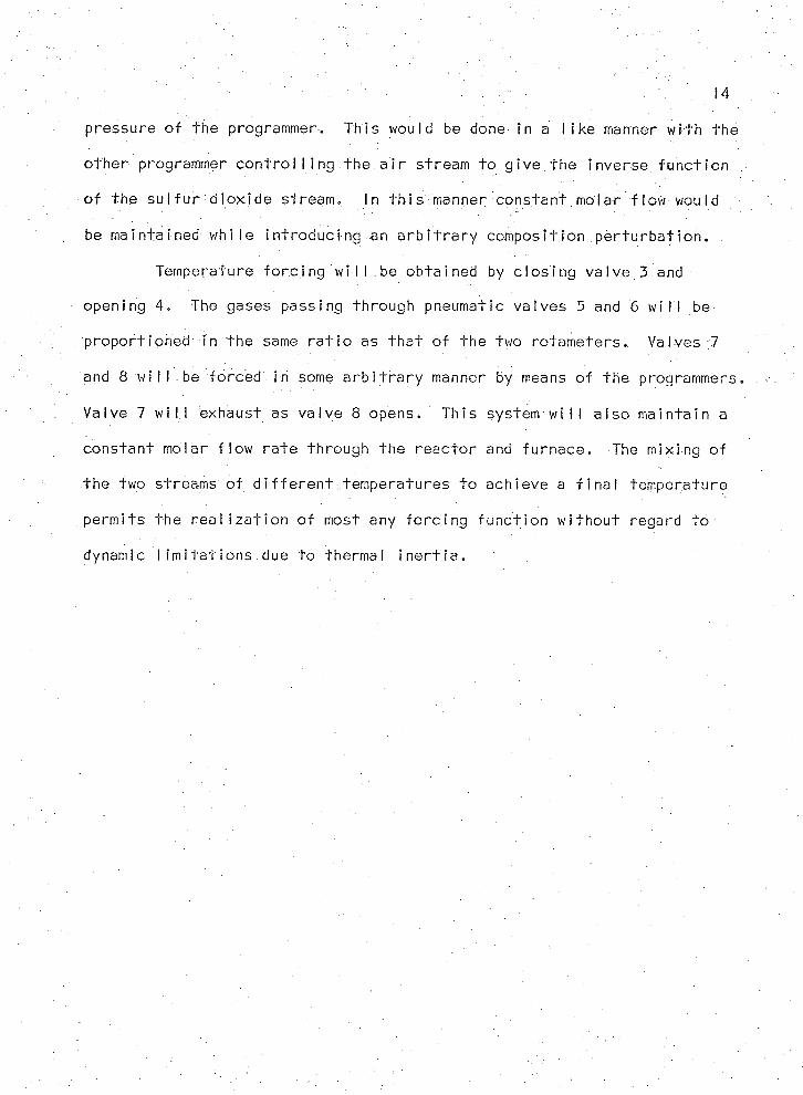
pressure o f the programmer. Th is would be done in a l i k e manner w i th the
o th e r programmer c o n t r o l l i n g the a i r stream t o g i v e the inverse f u n c t io n
o f the s u l f u r d io x id e stream. In t h i s manner cons tan t molar f low would
be maintained w h i le in t ro d u c in g an a r b i t r a r y compos i t ion p e r t u r b a t i o n .
Temperature f o r c i n g w i l l be obta ined by c lo s in g v a lve 3 and
opening 4. The gases passing through pneumatic va lves 5 and 6 w i I I be
p ropor t ioned in the same r a t i o as t h a t o f the two ro tam ete rs . Valves 7
and 8 w i l l be forced In some a r b i t r a r y manner by means o f the programmers,
Valve 7 w i l l exhaust as va lve 8 opens. Th is system w i l l a l s o m a in ta in a
cons tan t molar f lo w r a te through the r e a c to r and fu rnace . The mix ing o f
the two streams o f d i f f e r e n t temperatures t o achieve a f i n a l tempera ture
pe rm i ts the r e a l i z a t i o n o f most any f o r c i n g f u n c t io n w i th o u t regard t o
dynamic l i m i t a t i o n s due t o thermal i n e r t i a .
EXPERIMENTAL PROCEDURES
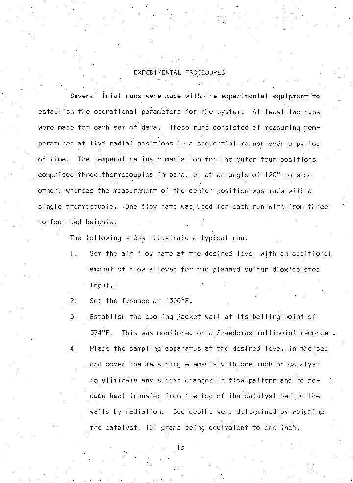
Several t r i a l runs were made w i th the exper imenta l equipment t o
e s t a b l i s h the o p e ra t io n a l parameters f o r the system. At le a s t two runs
were made f o r each se t o f d a t a . These runs cons is ted o f measuring tem
pera tu res a t f i v e r a d ia l p o s i t i o n s in a sequent ia l manner over a per iod
o f t im e . The temperature in s t ru m e n ta t io n f o r the o u te r f o u r p o s i t i o n s
comprised th re e thermocouples in p a r a l l e l a t an ang le o f 120° t o each
o th e r , whereas the measurement o f the c e n te r p o s i t i o n was made w i th a
s i n g le thermocouple. One f low r a te was used f o r each run w i th from th re e
t o f o u r bed he igh ts .
The f o l l o w in g steps i l l u s t r a t e a t y p i c a l run.
1. Set the a i r f low r a te a t the des i red level w i th an a d d i t i o n a l
amount o f f lo w a l lowed f o r the planned s u l f u r d io x id e s tep
i n p u t . .
2. Set the fu rnace a t I300°F .
3. E s ta b l i s h the c o o l in g j a c k e t wal l a t i t s b o i l i n g p o in t o f
574°F. Th is was monitored on a Speedomax m u l t i p o i n t r e c o r d e r .
■ 4. Place the sampl ing apparatus a t the des i red level in t h e ' bed
and cover the measuring elements w i th one inch o f c a t a l y s t
t o e l im in a te any sudden changes in f low p a t t e rn and t o r e
duce heat t r a n s f e r f rom the top o f the c a t a l y s t bed t o the
w a l l s by r a d i a t i o n . Bed depths were determined by weighing
the c a t a l y s t , 131 grams being e q u iv a le n t t o one inch.
15
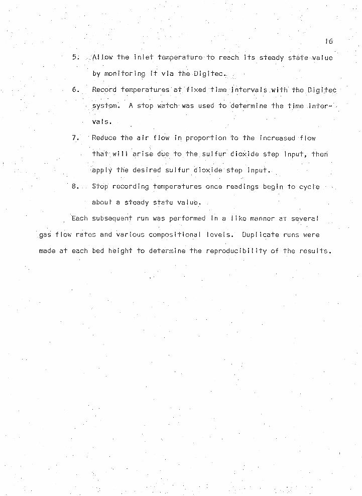
5. A l low the i n l e t tempera tu re t o reach i t s steady s t a te va lue
by m o n i to r in g i t v ia the D i g i t e c . .
6. Record temperatures a t f i x e d t im e i n t e r v a l s w i th the D i g i t e c
system. A stop watch was used t o determine the t ime i n t e r
v a l s .
7. Reduce the a i r f lo w in p r o p o r t io n to the increased f low
t h a t w i l l a r i s e due t o the s u l f u r d io x id e step in pu t , then
app ly the des i red s u l f u r d io x id e step in p u t .
8. Stop reco rd ing temperatures once readings begin t o c y c le
about a steady s ta te va lue .
Each subsequent run was performed in a l i k e manner a t several
gas f lo w ra te s and v a r iou s compos i t iona l le v e ls . D u p l i c a te runs were
made a t each bed he igh t t o determine the r e p r o d u c i b i l i t y o f the r e s u l t s .
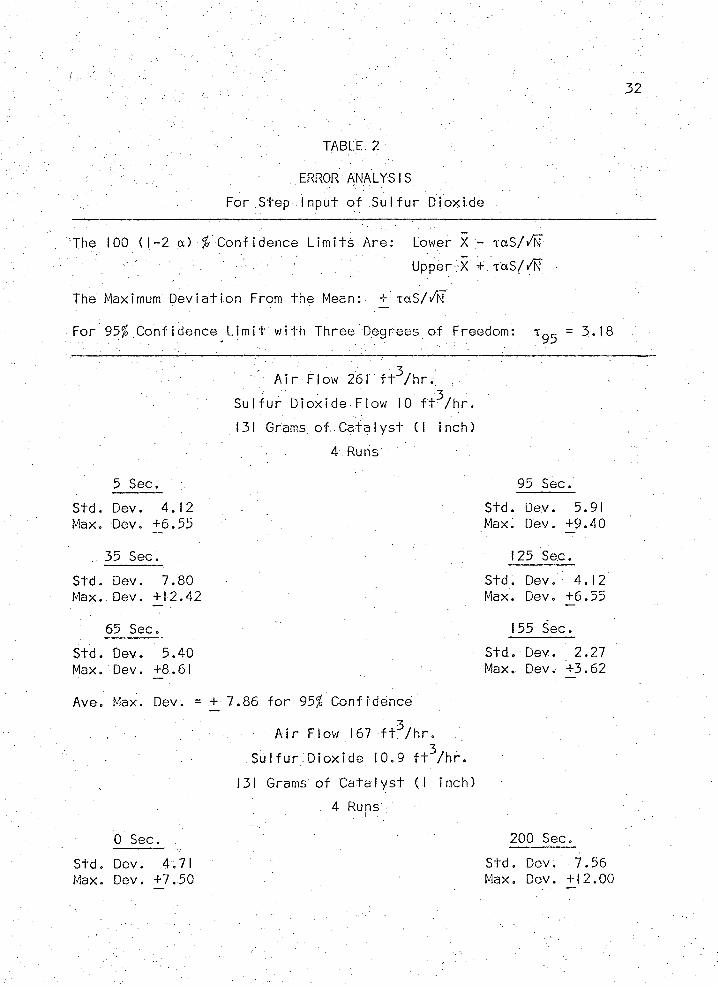
ERROR ANALYSIS
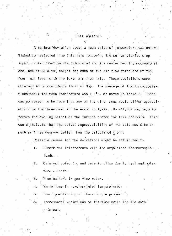
A maximum d e v ia t i o n about a mean va lue o f tempera ture was es tab
l i shed f o r se lec ted t im e i n t e r v a l s f o l l o w in g the s u l f u r d io x id e step
in pu t . Th is del v a t ion was c a lc u la te d f o r the c e n te r bed thermocouple a t
one inch o f c a t a l y s t h e igh t f o r each o f two a i r f low ra te s and a t the
fo u r inch level w i th the lower a i r f low r a te . These d e v ia t i o n s were
obta ined f o r a con f idence l i m i t o f 95%. The average o f the th re e d ev ia
t i o n s about: the mean.temperature was + 8°F, as noted }n Table 2. There
was no reason t o b e l ie v e t h a t any o f the o th e r runs would d i f f e r a p p re c i
ab ly f rom the th re e used in the e r r o r a n a l y s i s . No a t tempt was made t o
remove the c y c l i n g e f f e c t o f the furnace hea ter f o r t h i s a n a ly s i s . Th is
would i n d ic a te t h a t the ac tua l r e p r o d u c i b i l i t y o f the data could be as
much as th re e degrees b e t t e r than the c a lc u la te d j \ 8 ° F .
Poss ib le causes f o r the d e i v a t ions might be a t t r i b u t e d t o :
1. E le c t r i c a l , i n te r f e re n c e w i th the unsh ie lded thermocouple
Ieads .
2. C a ta l y s t po ison ing and d e t e r i o r a t i o n due t o heat and mois
t u r e e f f e c t s .
3. F lu c tu a t i o n s in gas f l o w . r a t e s .
4. V a r i a t i o n s in r e a c to r i n l e t temperature. .
5. Exact p o s i t i o n i n g o f thermocouple probes..
6. Incremental v a r i a t i o n s o f the t ime c y c le f o r the data
pr i n t o u t .

• 18
Q uan t iza t io n e r r o r due t o the inhe ren t round o f f e r r o r in
t h e d i g i t a l v o l tm e te r .
EXPERIMENTAL RESULTS AND DISCUSSION .
3A i r f lo w ra te s o f 167 a n d -261 f t / h r w i th t h re e impressed s tep i n
puts o f s u l f u r , d io x id e comprised the exper imenta l runs t o determine r a d ia l
tempera ture p r o f i l e s a t each o f t h re e c a t a l y s t bed h e ig h ts . For one run
fo u r bed h e i g h t s .were employed. Two inches o f 3/16 inch alumina prepack
were used f o r each run.; Bed he igh ts were, determined by we ighing the c a ta
l y s t on a beam balance. The i n l e t tempera ture was monitored along w i th
the bed temperature f o r each run on a 20 m i l l i v o l t d i g i t a l v o l tm e te r . Each
o f these temperatures were measured w i th respec t t o the wa l l tempera ture
as p re v io u s ly exp la ined . The v o l tm e te r read-ou t was quant ized t o .02 m i l l i
v o l t s , the reby i n c u r r i n g a q u a n t i z a t io n e r r o r o f nea r ly I°F f o r a l l data
obta in ed .
The i n l e t temperature was p l o t t e d as a fu n c t io n o f t im e . The ob
served saw-tooth v a r i a t i o n o f the i n l e t temperature was determined t o be
caused by the c y c l i n g o f the o n - o f f tempera ture c o n t ro l on the fu rnace .
Once s te a d y -s ta te is approached, the e f f e c t o f t h i s saw-tooth v a r i a t i o n on
each o f the r a d ia l p o s i t i o n s can be noted. The d e te c t io n o f t h i s pe r tuba -
t i o n e f f e c t p rov ides another i n d i c a t i o n on the s e n s i t i v i t y o f the tempera
t u r e measur ing equipment.
Several cross p l o t s o f the measured temperature data were made t o
i l l u s t r a t e and e x p la in the temperature response o f the bed both in the
dynamic and S tead y -s ta te s i t u a t i o n . These p l o t s are presented in F igs .
.6 t o 13. Figures 14 to 26 (Appendix A) g i v e the complete temperature
summary o f a i l runs made.
19
TE
MP
ER
AT
UR
E
CH
AN
GE
(A
T)
20
I 8 O-1
1 6 0 -
1 4 0 -
2 0 -
100-
8 0 -
6 0 —
6 . 1 9 % SO4 0 -
3 . 3 6 % SO
2 0 -
1 0 0 2 0 0 3 0 0 4 0 0 5 0 0 6 0 0 7 0 0 8 0 0 9 0 0 1 0 0 0T I M E ( S E C O N D S )
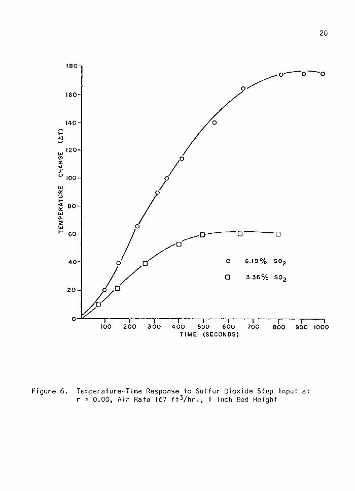
Figure 6. Temperature-Time Response to S u l f u r D iox ide Step Input a t r = 0 .00 , A i r Rate 167 f tVhr., • Inch Bed He igh t
TE
MP
ER
AT
UR
E
CH
AN
GE
(A
T)
21
200 —;
8 0 -
1 6 0 -
1 4 0 -
120
100-
8 0
6 0 —
4 0 -
20 -
6 . 1 9 % SO,
3 . 3 6 % SO,
1 0 0 2 0 0 3 0 0 4 0 0 5 0 0 6 0 0 7 0 0 8 0 0 9 0 0T I M E ( S E C O N D S )
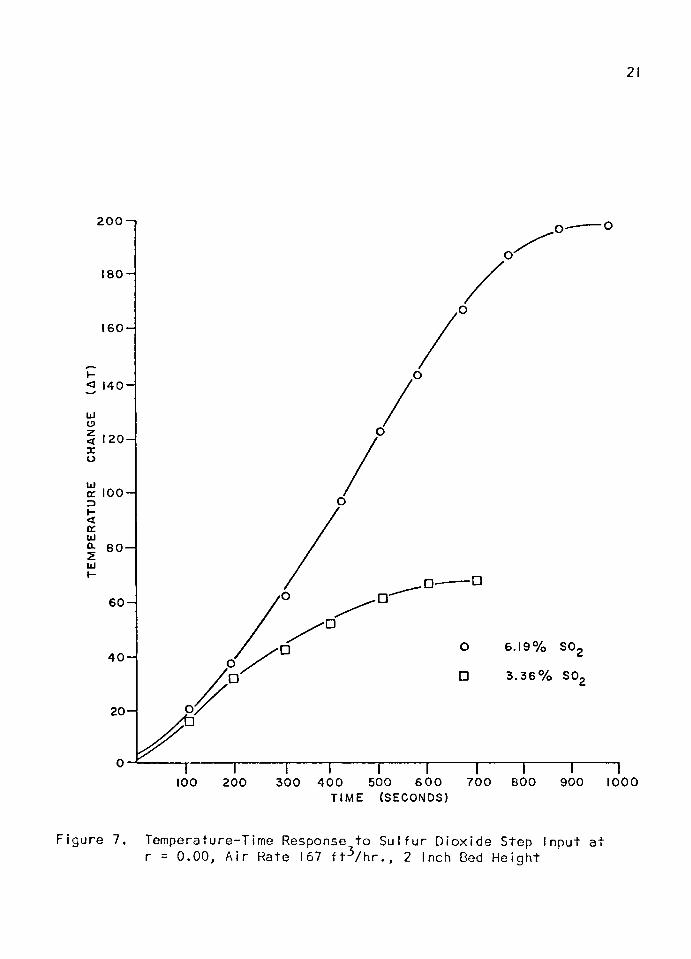
Figure 7. Temperature-Time Response t o S u l f u r D iox ide Step Input a t r = 0 .00, A i r Rate 167 f t ^ / h r . , 2 Inch Bed He ight
1000
TE
MP
ER
AT
UR
E
CH
AN
GE
(A
T)
22
2 2 0 —1
200 -
1 8 0
1 6 0 -
1 4 0 —
120-
100-
6 0 -
6 . 1 9 % SO,4 0 “
3 . 3 6 % SO
2 0 -
1 0 0 2 0 0 3 0 0 4 0 0 5 0 0 6 0 0 7 0 0 8 0 0 9 0 0 1 0 0 0 1100 120 0
T I M E ( S E C O N D S )
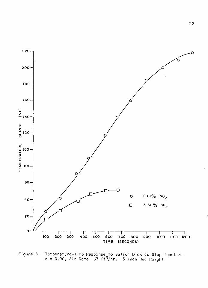
Figure 8. Temperature-Time Response to S u l f u r D iox ide Step Input a t r = 0 .00, A i r Rate 167 f t ^ / h r . , 3 Inch Bed He igh t
23
r
O 0 .0 0 0
o 0 . 2 12
0 . 4 2 37 3 0 —,
0 . 6 3 5
0 . 8 4 77 1 0 -
6 9 0 -
6 7 0 -
u j 6 5 0 -
6 3 0 -
6 1 0 -
5 9 0 -
5 7 0
2 3 4
B E D H E I G H T ( I N C H E S )
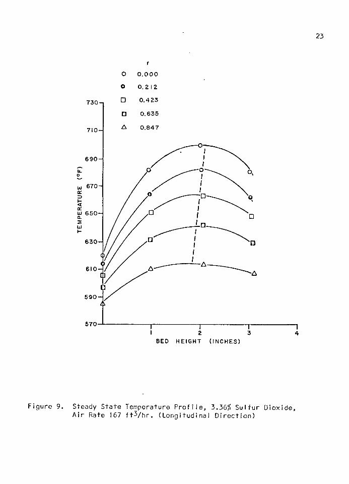
Figure 9. Steady S ta te Temperature P r o f i l e , 3.36% S u l f u r D iox ide , A i r Rate 167 f t ^ / h r . ( L ong i tud in a l D i r e c t i o n )

8 5 0
8 3 0
8 1 0
7 9 0
7 7 0
7 5 0
7 3 0
7 1 0
6 9 0
6 7 0
6 5 0
6 3 0
6 1 0
5 9 0
5 7 0
St c
24
O 0 .000
□ 0 . 4 2 3
0 . 6 3 5
A 0 . 8 4 7
B E D H E I G H T ( I N C H E S )
idy Sta te Temperature P r o f i l e , 6.19^ S u l f u r D iox ide , A i r ; 167 f t V h r . (Lo n g i tu d in a l D i r e c t i o n )
25
7 9 0 -1
7 7 0 -
7 5 0
7 3 0
=> 7 9 0 -
6 7 0 -
6 5 0 —
0.000
0.21 2
0 . 4 2 3
0 . 6 3 5
0 . 8 4 7
5 9 0 -
5 7 0
2 3 4
B E D H E I G H T ( I N C H E S )
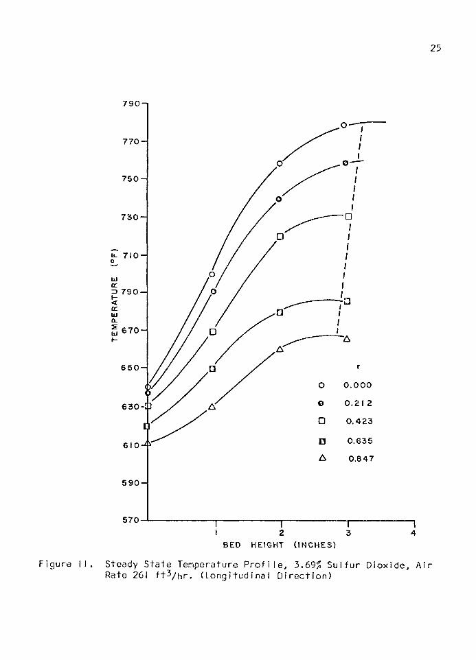
Figure I I . Steady Sta te Temperature P r o f i l e , 3.69% S u l f u r D iox ide , A i r Rate 261 f t ^ / h r . (Lon g i tu d in a l D i r e c t i o n )
26
7 9 0 -1
7 7 0 -
7 5 0 -
7 3 0 -
u. 7 1 0
3 690 —
LU
6 7 0 -
6 5 0 -
261 F T 3 / H R A I R R A T E
6 3 0 - 3 . 6 9 % SO
167 F T 3 / H R A I R R A T E
3 . 3 6 % SO6 10 -
5 9 0 -
5 7 0
2 3 4B E D H E I G H T ( I N C H E S )
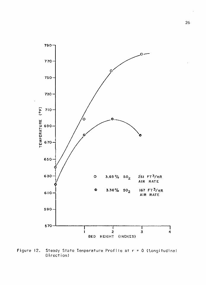
Figure 12. Steady Sta te Temperature P r o f i l e a t r = 0 (Lo n g i tu d in a l D i r e c t i o n )
27
1200-1
1100-
_ to X Q< z 1 0 0 0 - z o
9 0 0 -u
5 g 8 0 0 -
cc 5
H a 7 0 0 -
LU U1Z H
6 0 0 -
5 0 0
2 3 4
B E D H E I G H T ( I N C H E S )
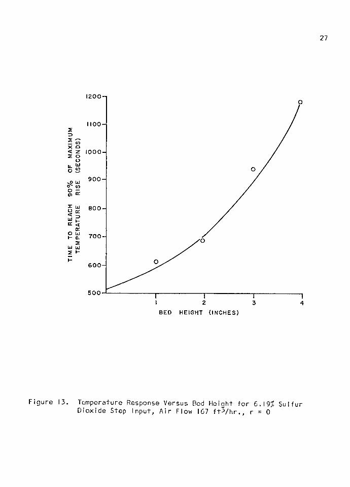
F igure 13. Temperature Response Versus Bed Height f o r 6.19% S u l fu r D iox ide Step Input , A i r Flow 167 f t V h r . , r = 0
■ 28
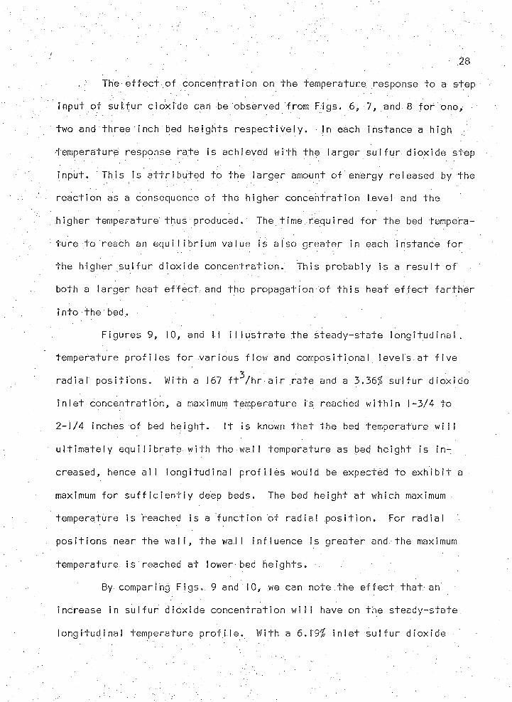
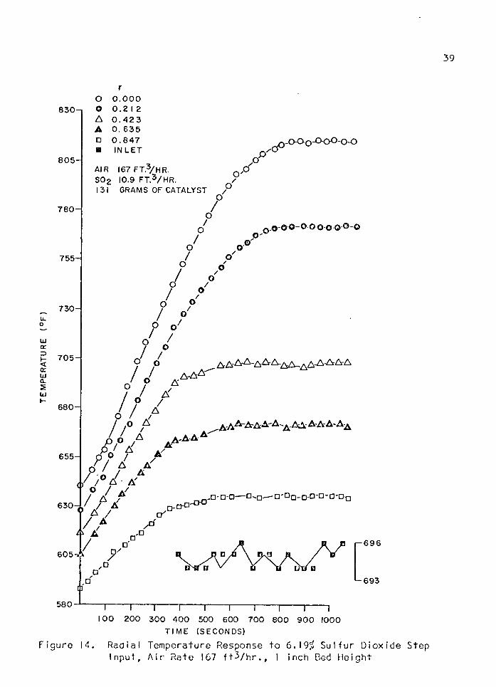
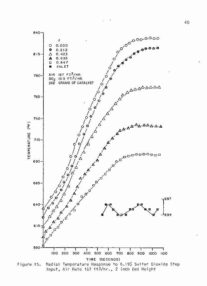
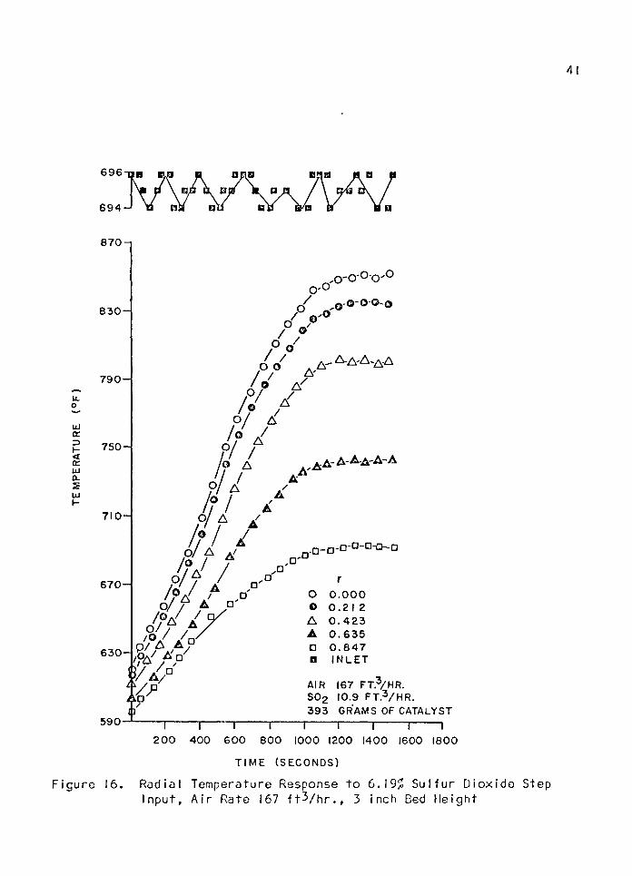
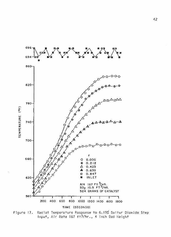
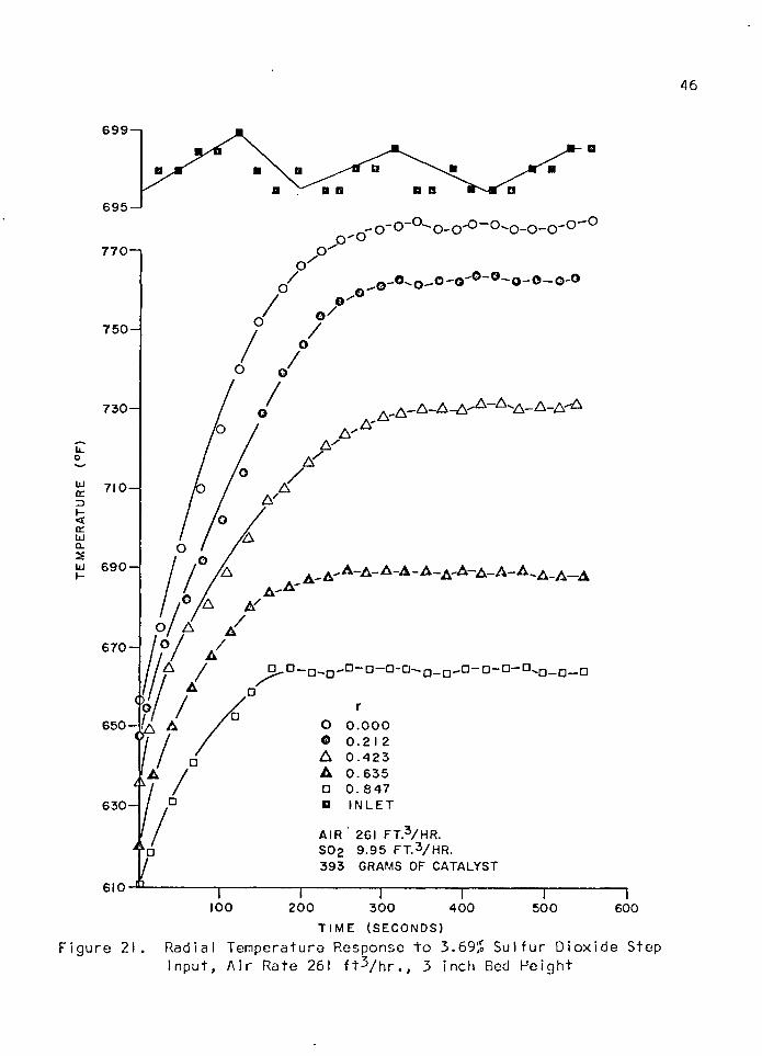
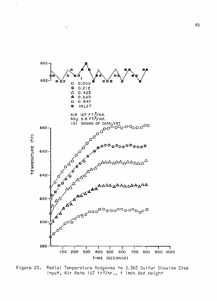
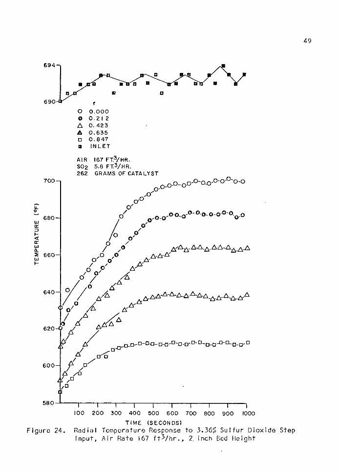
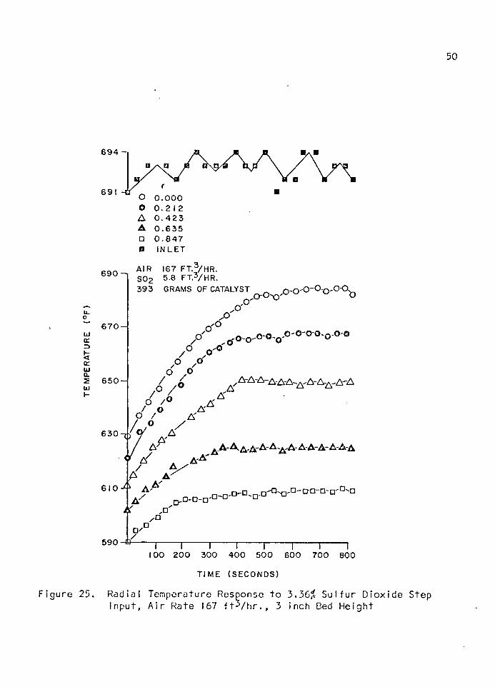
The e f f e c t o f c o n c e n t ra t io n on the temperature response t o a step
Input o f suI f u r c io x id e can be observed from F igs . 6, 7, and 8 f o r one,
two and th re e inch bed he igh ts r e s p e c t i v e l y . In each ins tance a high
temperature' response ra te is achieved w i th the la rg e r s u l f u r d io x id e s tep
in pu t . Th is is a t t r i b u t e d t o the la rg e r amount o f energy re leased by the
re a c t io n as a consequence o f the h igher c o n c e n t ra t io n level and the
h igher tempera ture thus produced. The t im e .required f o r the bed tempera
t u r e t o reach an equ i , l ib r ium va lue is a ls o g re a te r in each instance f o r
the h igher s u l f u r d io x id e c o n c e n t ra t io n . Th is probably is a r e s u l t o f
both a la rg e r heat e f f e c t and the propagat ion o f t h i s heat e f f e c t f a r t h e r
i n to the bed.
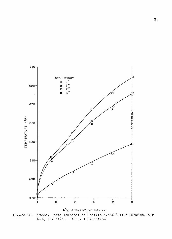
F igures 9, 10, and I I i l l u s t r a t e the s te a d y -s ta te l o n g i t u d i n a l ,
tempera ture p r o f i l e s f o r va r ious f lo w and compos i t iona l le v e ls a t f i v e
r a d ia l p o s i t i o n s . With a 167 f t ^ / h r a i r . rate and a 3.36$ s u l f u r d io x id e
i n l e t c o n c e n t ra t io n , a maximum tempera ture is reached w i t h i n 1-3/4 t o
2 -1 /4 inches o f bed h e ig h t . I t is known t h a t the bed temperature w i l l
u l t i m a t e l y e q u i l i b r a t e w i th the wa l l temperature as bed he igh t is i n
creased, hence a l l l o n g i tu d in a l p r o f i l e s would be expected t o e x h i b i t a
maximum f o r s u f f i c i e n t l y deep beds. The bed he igh t a t which maximum
temperature is reached is a f u n c t io n o f r a d ia l p o s i t i o n . For r a d ia l
p o s i t i o n s near the w a l l , the wal l in f l u e n c e is g re a te r and the maximum
temperature is reached a t lower bed h e ig h t s . •
By comparing F igs . 9 and 10, we can note the e f f e c t t h a t an
increase in s u l f u r d io x id e c o n c e n t ra t io n w i l l have on the s te a d y -s ta te
l o n g i tu d in a l tempera ture p r o f i l e . With a 6.19$ i n l e t s u l f u r d io x id e
■■■' : . ̂ . ■ =■■ ; 29
c o n c e n t ra t io n , the maximum tempera ture reached occurred between 2-3 /4
and 3 -1 /4 inches o f bed he igh t depending.upon the r a d ia l p o s i t i o n . Th is
temperature is g re a te r than t h a t o c c u r r in g w i th the 3 .36^ c o n c e n t ra t io n
. l e v e l , due t o the increased amount o f heat released a t the h igher con*
C e n t ra t io n .
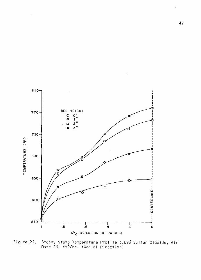
The e f f e c t o f increased gas v e l o c i t y on the s te a d y -s ta te l o n g i
t u d in a l temperature p r o f i l e can be seen by comparing F igs . 9 and I I .
Here, w i th a p p r o x i m a t e l y the same i n l e t s u l f u r d io x id e c o n c e n t ra t io n and
nea r ly tw ic e the a i r r a te , the l o n g i tu d in a l tempera ture p r o f i l e does not
reach a maximum a t two inches o f bed h e igh t as was the case, w i th the
3.36$ le v e l , but r a th e r con t inues to. increase, reaching a maximum a t
th re e inches. Th is is a t t r i b u t a b l e t o the sm a l le r q u a n t i t y o f heat r e
moved per u n i t volume o f r e a c t io n m ix tu re as a consequence o f the lower
residence t im e and hence reduced t im e f o r wal l c o o l i n g . F igure 12
d i r e c t l y i l l u s t r a t e s the above phenomena f o r the bed c e n te r thermocouple
o f F igs . 9 and I I .
F igure 13 i l l u s t r a t e s the in f lu e n c e o f bed h e ig h t on the t ime
requ i red f o r the thermocouple in the c e n te r o f the bed t o reach 90$.o f
i t s f i n a l e q u i l i b r i u m va lue . By e x t r a p o la t i n g the curve back to zero bed
h e igh t we note t h a t a f i n i t e t ime is requ i red f o r the zero bed he igh t t o
reach 90$ o f i t s e q u i l i b r i u m va lue . Th is is a t t r i b u t e d t o backmixing and
l a t e r a l heat conduct ion in the i n l e t r e g io n . I t is i n t e r e s t i n g to note
t h a t the curve is n o n l inea r and t h a t i f extended, a bounded bed he igh t
w i l l r e q u i re i n f i n i t e t im e to reach e q u i l i b r i u m .
A l l raw data temperature p r o f i l e s and temperature summaries can
be found in the appendices.
CONCLUSIONS AND RECOMMENDATIONS
Data on the in f lu e n c e o f gas f l o w ra te and magnitude o f a step
change in feed compos i t ion on the dynamic temperature response o f a f . ixed-
bed c a t a l y t i c r e a c to r were ob ta ined . A d e ta i l e d a n a ly s i s o f these data
is requ i red t o descr ibe the ac tua l heat t r a n s f e r mechanism invo lved; how
ever , a s a t i s f a c t o r y q u a l i t a t i v e exp lana t ion -has been advanced.
Al though some q u a n t i z a t io n e r r o r was exper ienced w i th the D ig ! te c
data logging system, i t proved a r e l i a b l e and accura te means o f reco rd ing
tempera ture data . I t shou ld prove equal Iy p r o f i c i e n t in handl ing concen
t r a t i o n and tempera ture data s im u l taneous ly in f u t u r e work. The remainder
o f the t e s t f a c i l i t y proved adequate f o r the present i n v e s t i g a t i o n ; how
ever , the o n - o f f c o n t ro l o f the fu rnace in troduced unwanted p e r t u rb a t i o n s
and s teps should be taken t o reduce o r e l im in a te these v a r i a t i o n s . A
s l i g h t amount o f decomposi t ion o f the heat t r a n s f e r f l u i d was noted, bu t .
t h i s caused no measurable change in the temperature o f the j a c k e t .
A more complete s tudy needs to be made t o determine what e f f e c t s
v a r i a t i o n s in c a t a l y s t s i z e and wa l l temperature w i l l have on the dynamic
and steady s t a te temperature responses.. A wider v a r i e t y o f f low ra te s
must be employed t o supplement the data obta ined in t h i s i n v e s t i g a t i o n .
30
31
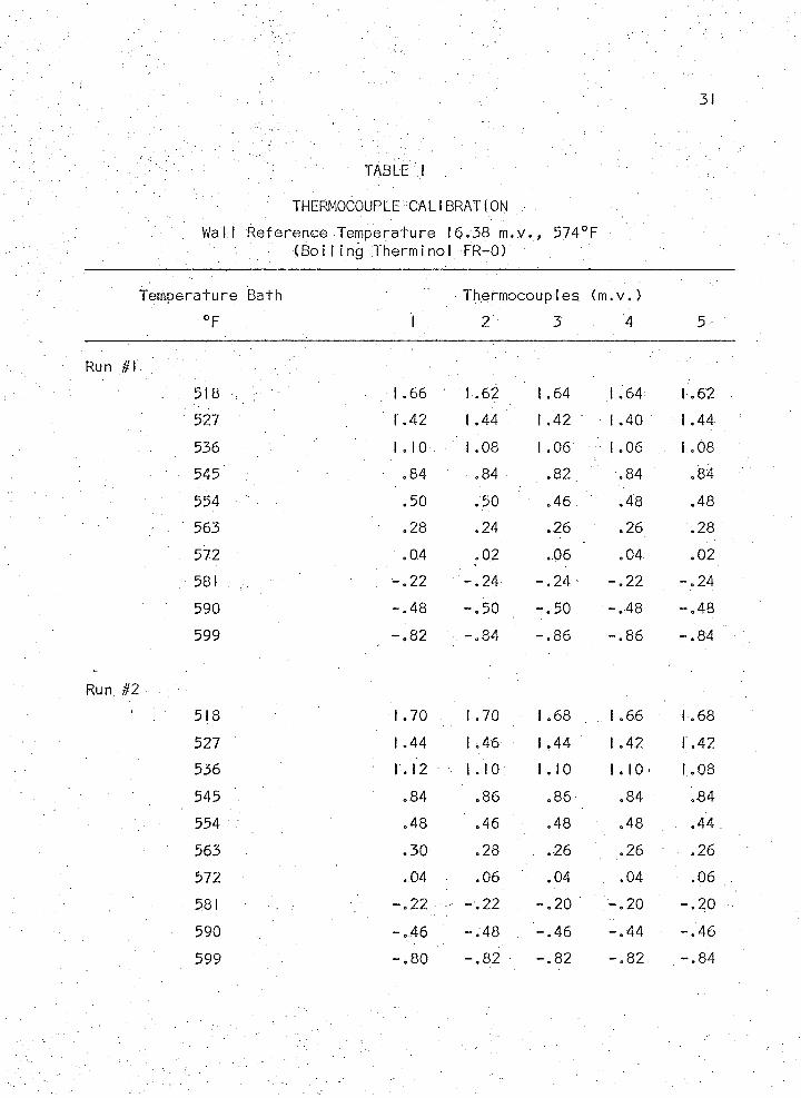
. ‘ TABLE I
THERMOCOUPLE CALIBRATION
Wal l Reference Temperature 16.38 m . v . , 574°F - (B o i l i n g Thermi no I FR-0)
Temperature Bath Thermocouples (m . v . )
°F 1 2 3 4 5
518 1.66 1 .62 1.64 1.64 1.62
527 1.42 1.44 1 .42 1.40 1 .44
536 1 .10 1.08 1.06 I .06 . 1.08
545 .84 .84 , -82 .84 .84
554 - .50 .50 .46 .48 .48
563 .28 .24 .26 .26 .28
572 .04 .02 .06 .04 .02
581 . - . 2 2 - .2 4 - .2 4 - .2 2 - .2 4
590 —. 48 - . 5 0 - .5 0 - .4 8
00<d-1
599 - .8 2 ' . - . 8 4 - .8 6 - .8 6 - .8 4
Run #2
518 1.70 . 1 .70 1.68 1.66 1.68
527 1.44 1.46 1 .44 1 .42 1.42
536 1.12 1 .10 1 .10 1.10' 1.08
545
'3-00 .86 .86 .84 .84
554 .48 .46 .. .48 .48 .44
563 .30 .28 . .26 .26 .26
572 .04 .06 ; .04 .04 .06
581 - .2 2 —. 22 - . 2 0 - .2 0 - . 2 0
590 - .4 6 - .4 8 - . 4 6 - .4 4 - .4 6
599 - . 8 0 - .8 2 - .8 2 - . 8 2 . - . 8 4
.32
TABLE 2
ERROR ANALYSIS
For Step Input o f S u l f u r D iox ide
The 100 (1 -2 a) % Conf idence L im i t s Are : Lower X - tocS//N
Upper X + TctS/
The Maximum D e v ia t io n From the Mean: + TaS//N
For 95% Conf idence L im i t w i th Three Degrees o f Freedom: = 3.18
A i r Flow 261 f t 3/ h r .3
S u l f u r D iox ide Flow 10 f t / h r .
131 Grams o f Cata I y s t ( I in c h )
4 Runs
95 Sec.
Std . Dev. 5.91 Max. Dev. +9.40
125 Sec.
Std . Dev. 4.12 Max. Dev. +6.55
155 Sec.
S td . Dev. 2.27 Max. Dev. +3.62
Ave. Max. Dev. = > 7.86 f o r 95% Conf idence' 3
A i r Flow 167 f t / h r .
< S u l f u r D iox ide 10.9 f t ^ / h r .
131 Grams o f C a ta l y s t (I inch)
4 Runs. I . '
0 Sec. 200 Sec.
Std . Dev. 4.71 Std . Dev. 7.56Max. Dev. +7.50 Max. Dev. +12.00
5 Sec.
S t d . Dev. 4.12Max. Dev. +6.55
35 Sec.
Std. Dev. 7.80 Max. Dev. j j . 2 .4 2
65 Sec.
Std . Dev. 5.40 Max. Dev. +8.61
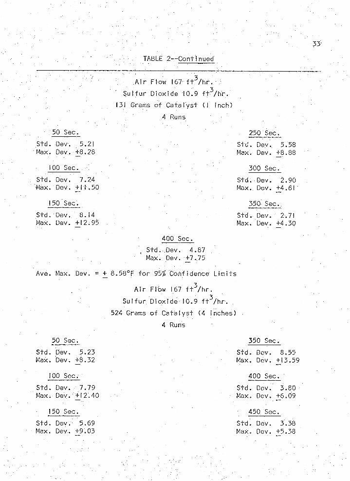
TABLE 2— C on tinued
:: ' ■ ■ : ■ 3 ■ ' ' Air Flow 167 f t /h r . J
S u l f u r D iox ide 10.9 f t ^ / h r .
131 Grams o f C a ta l y s t (I inch)
, S td . Dev. 4.87 Max. Dev. +7 <75
=.+_ 8 . 5 8 ° F - f o r 95^ Conf idence L im i t s
A i r Flow 167 f t ^ / h r .
Sul f u r D iox ide 10 .9 f t ^ / h r .
524 Grams o f C a ta l y s t (4 inches)
4 Runs
250 Sec.
Std. Dev. 5.58 Max. Dev. +8.88
300 Sec.
Std. Dev. 2.90 Max.. Dev. +4.61
350 Sec . .
S td . Dev. 2.71 Max. Dev. +4.30
400 Sec.
50 Sec.
Std. Dev. 5.21 Max. Dev. +8.28
100 Sec.
Std. Dev. 7.24 Max. Dev. + J I .50
150 Sec.
Std. Dev. 8.14 Max. Dev. +12.95
Ave. Max. Dev.
50 Sec.
S td . Dev. 5.23Max. Dev. +8.32
100 Sec.
Std . Dev. 7.79 Max; Dev. +12.40
150 Sec.
4 Runs
350 Sec.
S td . Dev. 8.55 Max. Dev. +J3.59
400 Sec.
Std . Dev. 3.80 . Max. Dev. +6.09
450 Sec.
S td . Dev. 5.69 Max. Dev. +9.03
Std. Dev. 3.38 Max. Dev. +5.38
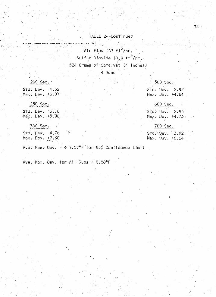
TABLE 2— C on tinued
34
- v. ■ ' ••••■ - - ; % ■- 3 .A i r Flow 167 f t / h r .
' ' ■ ' ■ ' 3S u l f u r D iox ide 10.9 f t / h r .
. .524 Grams o f C a ta l y s t (4 inches)
4 Runs
200 Sec. : 500 Sec,
S td . Dev. 4.32 Std. Dev. 2.92Max. Dev. +6.87 Max. Dev. +4.64
250 Sec. 600 Sec.
Std. Dev. 3.76 Std. Dev. 2.96Max. Dev. +5.98 Max. Dev. +4.73
300 Sec. 700 Sec.
Std. Dev. 4.78 Std. Dev. 3.92Max. Dev. +7.60 Max. Dev. +6.24
Ave. Max.- Dev. = + 7 .570F f o r 95% Conf idence L im i t
Ave. Max. Dev. f o r A l l Runs + 8.00°F
35
TABLE 3
MOD IFI ED REYNOLDS NUMBER CALCULATI ON
% = DPG V
BEO Temperature 700°F
E n te rin g Gas C om position 4% S02 , 18% 02 , 78% N,
Component: ;SP2 . °2 " S03
M 64 ; . 32 ' 80 28
T °K 430.3 154.3 491.4 126.0c
P Atm. 77.7 49.7 83.6 33.5c
Pc M ic ropo ises ... 411 250 469 180
M = .04(64) + .18(32) + .78(28) = 3 0 . 1 2m
I r = .04(430.3) + .18(154 .3 ) + .78(126) = 143.1c
Pc ' = .04 (77 .7 ) + .18 (49 .7 ) + .78 (33 .5 ) = 3 8 . 1 5
Pc ' = .04(41 I ) + .18(250) + .78(180) = 201.4 .
: TR = f S = 4 ,5
PR " 3 8 .2 ■°262
“ r = ' • 6
V = (yR) ( y . ) = 1 .6(201.4) = 322 mp
u = 322(.000242) = .0775 I b s / f t - h r .
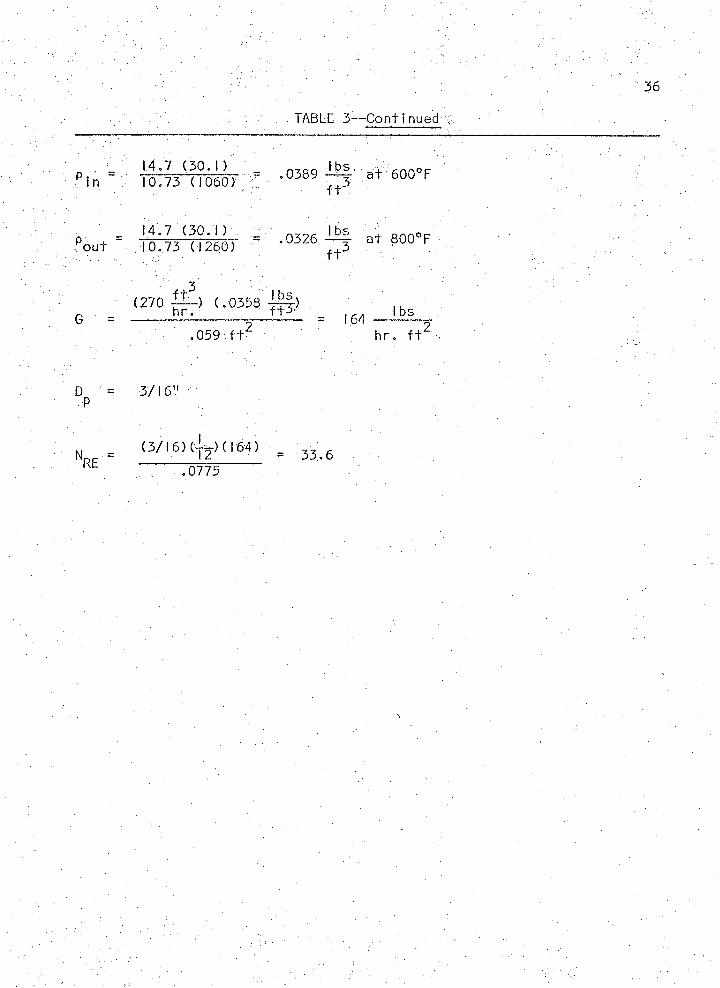
TABLE 3— C on tinued
p i n T o r f r m r = •0389
14.7 (3° . 1) V _0326Tout 10.73 (1260)
3 . ■ v ;y -(270 ^ - ) ( .0358 j g - )
' .059 f t 2 :
D = 3 /16"P
Nor- = (3/1 6) ( , 2 ) ( I 64) = 33<
— ~ o m ~ :
a t 600° F f t :
- ^ 1 a t 800° F f t 3
164 - l b s _h r . f t
6

NOMENCLATURE:
t . t d i s t r i b u t i o n , the r a t i o , w i th o u t s ig n , o r a v a r i a t e normal ly .
d i s t r i b u t e d about zero, t o an independent es t im a te o f i t s
standard d e v ia t i o n
x A r i t h m e t i c mean va lues o f x
s Est imate o f standard d e v ia t i o n
N Number o f obse rva t ions o f i n d iv i d u a l samples:
a P r o b a b i I i t y
p V i s c o s i t y I b / f t - h r .
G V e lo c i t y l b / f t - h r .
x D is tance f t
D P a r t i c l e d iamete rP
p Dens i t y l b / f t ^
M Mo lecu la r we igh t \
N ^ Reynolds number
T Temperature
P Pressure -
Su bsc r ip ts
c C r i t i c a l
R Reduced
37
APPENDIX A
RAW TEMPERATURE DATA
8 3 0
8 0 5
7 8 0
7 5 5
7 3 0
7 0 5
6 8 0 -
6 5 5 -
6 3 0 -
6 0 5 -
5 8 0 -
ure
39
^ p - a o o - o o o - o - o
o
o o.oooO 0.2 12 A 0 . 4 2 3 A 0 . 6 3 5 □ 0 . 8 4 7B I N L E T
AI R 167 FT. 3/ H R . QjcfS O 2 10.9 F T . 3 / H R . /131 GRAMS OF CATALYST //
Q Q.O-O O-O G O o o 0 ' 0
J /
/// //
/ / °9 P A A ^ * ^ - A ^ ^ - A A ~ a A A -A A A
/ / ^ ̂ / a// /Az A-A-A-^
f :z
z
,D-D-D— D^Q—- D 'D q- q .D-D-D-D^d-cK H ^
u^a 3 u V a
- 6 9 6
- 6 9 3
I I I I I 1------- 1------- 1------- 1-------110 0 2 0 0 3 0 0 4 0 0 5 0 0 6 0 0 7 0 0 8 0 0 9 0 0 1 0 0 0
T I M E ( S E C O N D S )
4. Radial Temperature Response t o 6.19$ S u l f u r D iox ide Step Inpu t , A i r Rate 167 f t V h r . , I inch Bed He igh t
8 4 0
815
7 9 0
7 6 5
7 4 0
7 1 5
6 9 0
6 6 5
6 4 0
6 1 5
5 9 0
15.
40
o 0 . 0 0 0e 0 . 2 1 2A 0 . 4 2 3A 0 . 6 3 5□ 0. 8 4 7■ I N L E T
AIR 167 F
r O'
O'/
O-O-O'0 '0 '0 0
q-OO-O'O
S 0 2 10.9 FT.3 / H R .2 6 2 GRAMS OF CATALYST
P
O
If/ / °// A'
a .A-AA"^"A "A 'A
o V//. » ? Llit
/A
A
A/A A 'A A -A-A-A
A
o o /A
^O-D'D'D-D-D-D-D-a
/ z
y6 9 7
6 9 4
f°/l £.v // /
/ □ o'/
I I I I I I I I I I 11 0 0 2 0 0 3 0 0 4 0 0 5 0 0 6 0 0 7 0 0 8 0 0 9 0 0 1000 1100
T I M E ( S E C O N D S )
Radial Temperature Response t o 6.19% S u l f u r D iox ide Step Inpu t , A i r Rate 167 f t 3 / h r . , 2 inch Bed Height
TE
MP
ER
AT
UR
E
(°F
)41
F ig u re
696-nB
6 9 4 —1
nnn BHO
8 7 0 —1
8 3 0 -
7 9 0 -
7 5 0 -
7 1 0
6 7 0 -
6 3 0 -
5 9 0 -
0 ' ° A.0 '0 '0 *0 '°
.O'O'OO^Q
/ /A zA °
/0/ /
#f/Z
/
,& A - A-A-a-A-A
/▲Z
,o A
„D-n-D-D-D-CKD
/ _/Dcr
o / y / /
i? £ ?Z o z
o 0 . 0 0 0o 0 . 2 12A 0 . 4 2 3A 0 . 6 3 5□ 0 . 8 4 7n I N L E T
2 00
AI R 167 FT. 3/ H R .S 0 2 10 .9 F T . 3 / H R .3 9 3 G R A M S OF CATALYST
— 1-1 1 1 1 1------------------------------------------ 1 14 0 0 6 0 0 8 0 0 1 0 0 0 1 20 0 1 4 0 0 1 60 0 1 8 0 0
T I M E ( S E C O N D S )
16. Radial Temperature Response to 6.19% S u l f u r D iox ide Step Inpu t , A i r Rate 167 f t V h r . > 3 inch Bed Height
TE
MP
ER
AT
UR
E
(°F
)
860-1
8 2 0 -
7 8 0 -
7 4 0 -
7 0 0 -
6 6 0 —
6 2 0 -
5 8 0 - ®
//
,0 -0 -0 -0 -o
.0-0—©-O
A"^ ^ -A - aA A
O £ Az
#
/ / a ' a - A - A - A - n̂ —An/si.D -0'a'o /DNa^D' n' D' ' D'"D
$>>
o 0 . 0 0 0o 0 . 2 1 2A 0 . 4 2 3A 0 . 6 3 5□ 0 . 8 4 7n I N L E T
/ D// AIR 1 6 7 F T . 3/ H R .S 0 2 1 0 .9 F T 3/ H R .5 2 4 G R AM S OF CATALYST
_1 , |--------- 1-------- 1 1 1---------1 12 0 0 4 0 0 6 0 0 8 0 0 1 0 0 0 1 2 0 0 1 4 0 0 1 60 0 1 80 0
T I M E ( S E C O N D S )
Figure 17. Rad i a I Temperature Response t o 6.19/= S u l f u r D iox ide Step Input , A i r Rate 167 f t 3 / h r . , 4 inch Bed Height

TE
MP
ER
AT
UR
E
(°F
)43
8 9 0 - 1
BED H E I G H T
8 5 0 -
8 1 0 -
7 7 0 -
LU
7 3 0 -
UJ
6 9 0 -
6 5 0 -
6 1 0 -
5 7 0
8 .6 .4 .2 0r /r 0 ( FR AC T IO N OF RADI US)
Figure 18. Steady S ta te Temperature P r o f i l e , 6 . I9 £ S u l f u r D iox ide , A i r Rate 167 f t V h r . (Radial D i r e c t i o n )
TEM
PER
ATU
RE
(°F
)
44
696-1
6 9 4 -
O 0.000
A 0 .4 2 3 A 0 .6 3 5 □ 0 .8 4 7D INLET
AIR 261 FT.3/HR.S02 10.0 FT.5/HR.131 GRAMS OF CATALYST7 IO - i
o —o - o - o6 9 0 -
A-.A _ A ,A 'n \A, A A -A 'A _
6 7 0 -
650-v A
0-0—O—□6 3 0 -
610100 200 3 00 4 0 0 5 0 0
TIM E (SECONDS)
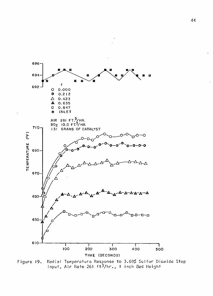
F i g u r e 19. R a d i a l T e m p e r a tu r e Response t o 3.69^ S u l f u r D i o x i d e Step I n p u t , A i r R a t e 261 f t 3 / h r . , I inch Bed H e i g h t
TEM
PERA
TUR
E (°
F)
45
6 9 9 - ,
•O—o- O " ° O" °~-o-o750-i
0— 0.
7 3 0 -
A -A _ a - AxA~"A ' A -A -a ' A7 1 0 -
6 9 0 -
A A-A -A -xA - A -A 'A
6 7 0 -
A 0 .4 2 3 A 0 .6 3 5
6 3 0 - INLET
AIR 261 FT. /HR.SOg 9.95 FT.3/HR.262 GRAMS OF CATALYST
610
100 200 300 400 500
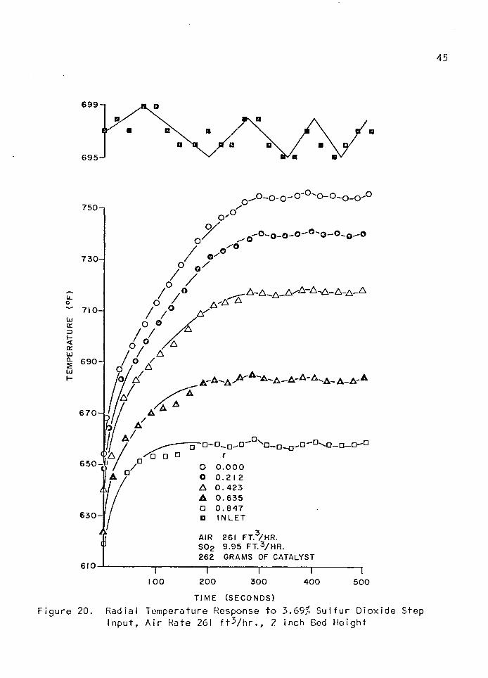
TIME (SECONDS)F igu re 20. Radia l Temperature Response to 3.69% S u lfu r D iox ide Step
In p u t, A ir Rate 261 f t V h r .» inch Bed H e igh t
TEM
PERA
TUR
E (°
F)
46
6 9 9 - i
B BB a6 9 5 —*
0 ~ 0 0 ' ^ 0 - 0 ' ° 0 ' ' 0- 0 - 0''0" 0
7 7 0 -1
o-0-© -0'® '0"0"® -0' 0'0
7 5 0 -
A „ A _ A - A A - A - ^7 3 0 -
7 1 0 -
690 — A ~A- A -A - A - A 'A -A -A - A ̂ A -A —AA '
6 7 0 -
a"D'~D-D-0-D ~D"_D'-D-D—□
O 0.0006 5 0 -
A 0 .4 2 3 A 0 .6 3 5
IN L E T6 3 0 -
AIR ‘ 261 FT.3/HR.SOg 9.95 FT.3/HR.393 GRAMS OF CATALYST
100 200 300 400 500 600T IM E (SECONDS)
F igu re 21. Radia l Temperature Response to 3.69% S u lfu r D io x id e Step In p u t, A ir Rate 261 f t V h r . , 3 inch Bed H e igh t
TEM
PERA
TUR
E (°
F)
47
8 10-1
BED HEIGHT7 7 0 -
7 3 0 -
6 9 0 -
6 5 0 -
Lul
6 1 0 -
UJo
5 7 0
.8 .6 4 02
r/r0 (FRACTION OF RADIUS)
F igu re 22. Steady S ta te Temperature P r o f i le 3.69# S u lfu r D io x id e , A ir Rate 261 f t ^ / h r . (R adia l D ire c t io n )
TEM
PER
ATU
RE
(°F
)
48
6 95 —i
BB692-"
O 0.000 O 0 . 2 1 2A 0 .4 2 3 A 0 . 6 3 5 □ 0 . 8 4 7Q INLET
680 —i
6 6 0 4
6 0 0 -J
AIR 167 FT.3/HR.SO2 5.8 FT.3/H R .131 GRAMS OF CATALYST
^ 0<).OOo.O"Oo_o.O^
<jo
o 0 , o 0 0 - o 0 o o o 0 o o o °
0 ° ,0^ a AA-A.aA-Aa A A a a .a a
6 4 0 —1 o ' / 6 X ' A q/ ,© zA
kz o 0 / A A-AAA-AA-AA a A-AaA A
a / ,a a / A . o - o - o 'D ' D ' d -d - D ' d ' c:]' 0 - d d ' c l q d ' d
□
580 1 --------- 1--------- 1----------1---------1----------1----------1--------- 1--------- r—100 200 300 4 00 500 600 700 800 9 00
TIME (SECONDS)
—I1000
F igu re 23. Radia l Temperature Response to 3.36$ S u lfu r D io x id e Step In p u t, A ir Rate 167 f t V h r . , I inch Bed H e igh t
TE
MP
ER
AT
UR
E
(°F
)49
6 9 4 - i
6 9 0
O 0.000O 0.2 12 A 0 . 4 2 3 A 0 . 6 3 5 □ 0 . 8 4 7O IN L E T
A IR 167 FT.3/ H R .SOg 5 .8 F T .3 /H R .2 6 2 G R A M S OF C A T A L Y S T
7 0 0
6 8 0 -
6 6 0 -
6 4 0 -
Q . O - O - O 0 ' 0 ' 0 '0 '0 ° 0 ' 0 ' 0
vOo z
/o-o'O O'0' 0 - ° 0 ' 0 "0 0 "0'0 '0
A ^ A ' ̂ "^-A- A A -A ^ ^ _ AO'
0 .0 0,0 A-A-A'
t / & / y A A - A - A - A - A A 'A -A .A A - A . ^ A A
° / ../Y Ao/ A
Q /A /v
6 2 0 - v V
6 0 0 —
5 8 0
A -A A
/y
A /DO
A / / o A '/D
□
□
I I l I I I I I I I 1 0 0 2 0 0 3 0 0 4 0 0 5 0 0 6 0 0 7 0 0 8 0 0 9 0 0 1000
T I M E ( S E C O N D S )F igu re 24. Radia l Temperature Response to 3.36$ S u lfu r D io x id e Step
In p u t, A ir Rate 167 f t V h r . , 2. inch Bed H e igh t
Figure
50
6 9 4 - i
69 O 0.000 O 0 . 2 1 2A 0 . 4 2 3 A 0 . 6 3 5 D 0 . 8 4 7 D I NLET
CQn AIR 167 FT.^/HR.6 9 0 -1 S02 5.8 FT.3/HR.
393 GRAMS OF CATALYST
u.o~ 670UJd:3
ccU Ja5 650 —|UJ I-
610
5 9 0 -B
,CrOx),o-0 ' 0 -o-0 ' 0 -ob
'O
p ' o-o-o-o-o '0 ' 0"0 0 ' 0 0 '0//*O / ° Az ^
o / ° o7 / 0
.A'
/r,° .zA'
630 ' O / A . A/ Ay a .A- A . A '/v^A- A A A - A -A -^f / a/ * 1
A ^ A ^
^o-a-a-o-o-0- 0^ - ^ ' 0' " 0-0-0' 0' 0
Dz/
I I I 1 I I I I 100 200 300 400 500 600 700 800
TIME (SECONDS)
25. Radia l Temperature Response to 3.36% S u lfu r D iox ide Step In p u t, A ir Rate 167 f t - V h r . , 3 inch Bed H e igh t
TE
MP
ER
AT
UR
E
(°F
)
51
7 I O —»
BED H E IG H T
6 9 0 -
6 7 0 -
6 5 0 -
6 3 0 -
6 1 0 -
5 9 0 -
5 7 0
.6.8 .2.4 0
r / r Q (FR A C T IO N OF R ADIUS )
F igu re 26. Steady S ta te Temperature P r o f i le 3.36$ S u lfu r D io x id e , A ir Rate 167 f t V h r . (R adia l D ire c t io n )
-CE
NT
ER
LIN
E

APPENDIX B .
TEMPERATURE SUMMARIES
52
53
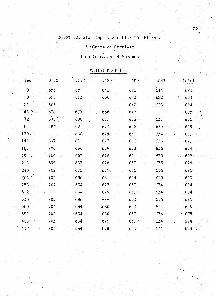
3 .690 SOg Step In p u t , A i r Flow 2 6 1 F t ^ / H r .
131 Grams o f C a ta I y s t
Time Increm ent 4 Seconds
Radia l P o s it io n
Time 0.00 .212 .423 . 685 .847 In 1 e
0 655 651 64.2 628 614 693
0 . 657 653 650 633 620 693
24 . 666 — — — . 640 629 694
' m % 676 677. 666 647 —--- 695
72 687 686 ,■ / 673 652 637 695
96 694 691 677 652 . 635 - 695
120 ----- 690 675 650 634 693
144 697 691 677 652 635 693
168 700 694 679 653 636 . 694
192 700 : 693 678 651 633 693
218 699 693 678 653 635 694
240 702 695 ' 679 655 6.36 695
264 704 696 681 654 636 695
288 v , 702 694 677 652 634 694
312 694 679 653 634 694
336 703 696 653 636 695
360 704 694 680 653 634 695
384 702 694 680 653 634 . 695
408 703 694 679 653 634 694
432 703 694 678 653 634 694
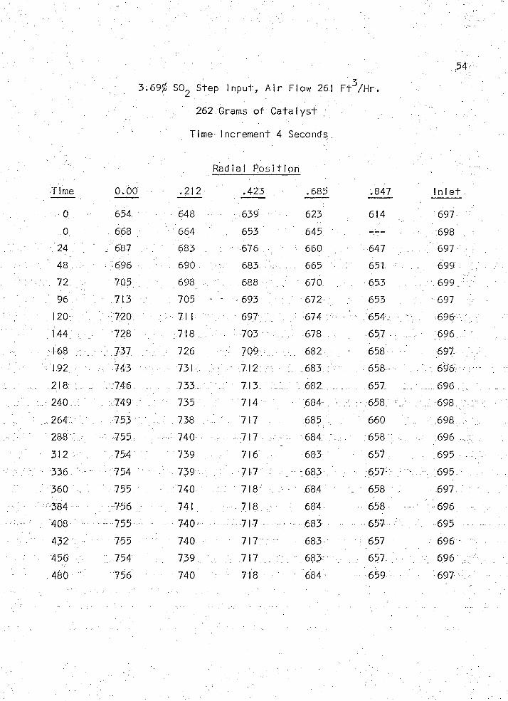
54
262 Grams o f C a ta ly s t
Time Increm ent 4 Seconds.
> . Radia l Pos i t io n
Time 0 ,00 .212 .423 . .685 .847 I n le t
0 654. 648 ,639 623 614 697
0 668 664 .. 653 645 698
24 ' . 687 683 676 ' 660 647 697
48 696 690 683 665 65 1 . 699
72 705 698 688 670 . 653 . 699.
96 . ' 713 , 705 693 672 653 697
, 120 71 I ' ' 697 674 ' - - 654 : 696
144 . 728 718 703 678 . 657 - 696
168 . 737 . . 726 \ 709 ., 682 , ; • 658 ... 697
192 . , -743 /- / , v \73 l-.: ' i ,.r 712 ' 683 : . 658 . t : 696- ̂ -
... - ... 218 : . . . : 746 ..................733.. 713 . 682 657 . . 696.
... 240 749 735 714 684 Z 658. . 698 .
264 753 738 717 685 , 660 698
, . • . " 288 - : 755 •• ' 740 717 "... 684 . ... .. 658 ■ . .. , 696 .,Z
312 754 ;; 739 716 V 683 657 695 .z
336 - 754 ' 739 '' ' . y 71 7 6 8 3 .■■ 657 695
Z . 3 6 0 755 740 ; : 718 684 \ 658 . 697 .
384 756 741 718 - 684 658 • 696
..... Q6 . ..........— "'755 — .~. —...~ 740 "' ■ —--... — ’I*7 : —■.■ . * - 683 ■ ■ ■■■ 657 — — —695 . —
432 : 755 740 717 683 657 696
■ 456 754 739 717 683 .. 657 696 ;
480 756 - 740 718 684 659 697
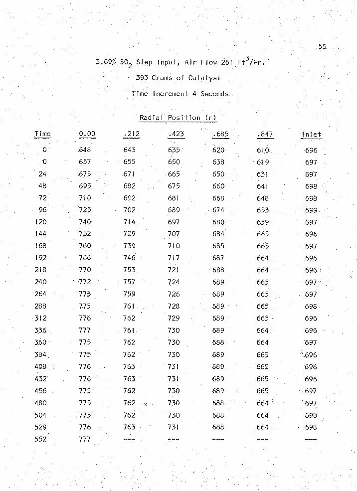
55
3.69% SO^ Step In p u t , A i r Flow 261 F t ^ / H r .
393 Grams o f C a t a l y s t
Time Increm ent 4 Seconds
Radi a 1 P o s it io n ( r )
I i me 0.00 .212 .423 . 685 . .847 In le t
0 648 643 635 620 610 696
0 657 655 650 . 638 619 697
24 . 675 671 665 650 631 697
48 . 695 682 : 675 : 660 641 698
72 710 692 681 668 648 . 698
96 725 702 689 674 . 653 699
120 740 714 697 680 659 697
144 752 729 707 684 665 696
168 760 739 710 685 665 697
192 : 766 746 717 - 687 664 696
218 770 753 721 688 664 696
240 772 757 724 689 665 697
264 . 773 759 726 689 665 697
288 , 775 761 728 . . 689 665 698
312 776 762 729 689 665 696
336 . 777 . 761 730 689 664 696
360 775 762 730 688 664 697
384' 775 762 730 689 665 696
408 776 763 731 689 665 696
432 776 763 731 689 665 696
456 • 775 762 730 689 665 . 697
480 775 762 730 688 664 697
504 775 ' 762 730 688 664 698
528 776 > 763 . 731 688 664 698
552 777 — • — — m+mm — — —- — — —
56
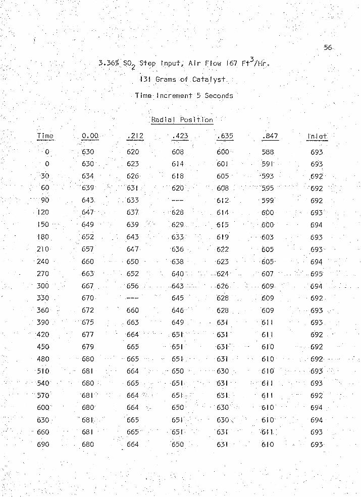
3 .3 6 ^ SO^ Step In p u t , A i r Flow 167 F t ^ / H r .
131 Grams o f C a t a l y s t
Time Increm ent 5 Seconds
R adia l P o s it io n
Time 0.00 .212 • .423 .635 .847 in 1 ei
0 630 620 608 600 588 693
0 ' 630 . ■ 623 614 601 - 591 693
30 v ' 634 . 626' 618 605 593 69260 . . 639 -A 631 620 608 : 595 " 692
90 . 643 633 ' — - . 612 599 692
120 647 . 637 ■ 628 614 . 600 ; - 693
150 649 639 629 615 ' ' . - 600 694
180 652 ' 643 • 633 " " 619 603 693
210 •; 657 647 636 , 622 605 693
240 . 660 650 • 638 623 605- 694
270 663 652 640 • -624 - 607 - v 695
300 , 667 656 • -643... 626 . . 609 694
330 670 ----- . 645 628 . 609 692
360 672 660 ' 646 628 . 609 693
390 , 675 663 649 ' - 631 61 1 693
420 . 677 - 664 - 651 631 61 1 692
450 679 665 651 631 - 610 ....- 692
480 680 - 665 - 651 631 - - 610 -. 692
510 " 681 664 - 650 1 ; • 630 610 - . 693
540 680 665 ■ 651 631 61 1 v 693
570 681 ■ 664 651 631 61 1 - 692
600 680 664 650 630 610 694
630 681; 665 651 630 ; 610 694
660 681 : 665 ■ 651 631 61 1 693
690 680 -• 664 650 631 610 693

57
3 .36$ SC> 2 Step In p u t , A i r Flow 167 F t ^ / H r .
131 Grams o f C a t a l y s t
Time Increm ent 5 Seconds
. Ra d i a I Posi f i o n
Continued
Time 0.00 .212 .423 .635 .847 I n l e t
720 680 664. 650 630 , 609 692
750 , 680 . 664 , 650 631 610 694
780 682 665 652 631 611 694
58
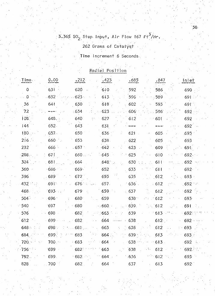
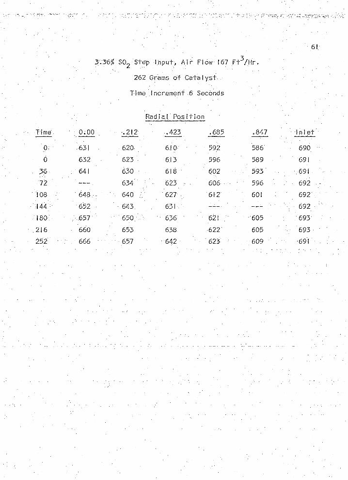
3.36% SOg Step In p u t , A i r Flow 167 F t ^ / H r .
262 Grams o f C a ta l y s t
Time Increm ent 6 Seconds;
Radia l P o s it io n
T i me 0.00 .212 .423 .685 .847 In 1 e"
0 631 620 610 592 V 586 690
■ ; 0 632 623 613 . 596 ■ 589 691
36 641 - 630 618 , , 602 . 593 691
72 — T— " 634 '.r. 623 . 606 : 596 V t ; ; : 692
108 . . 648 640 627 : 612 601 , y 692
144 652 643 631 . -------- — — — 692180 657 650 636 621 605 693216, 660 653 638 622 605 693
232 666 .. 657 642 ■ 623 - 609 , • 691
288 : 671 660 645 625 610 - 692
324 . - 681 .. - 664 . 648 , 630 ; : 611 : 692
360 686 669 652 633 61 1 692
396 : . 689 ' 672 655 635 612 693
432 691 676 657 . 636 612 . 692
468 6 9 3 - , 679 659 ■ 637 612 ; - 692
504 696 680 . . 659 638 612 693
540 697 680 ■ 660 ■■■.. 639 612 691
576 - 698 - 682 ' 663 639 613 : 692
612 - - 699 - — ■, 682 - - 664 '"' — - 638 612 692
648 698 - 681 663 638 612 ■ 693
684 - 699 f ' ' 683 ■; 664 . - 639 , 613 693
720 700 - 683 664 638 613 692
756 v 699 682 663 ■ 638 ' 612 692
792 ' 699 682 664 636 612 693
828 .. 700 682 664 ’ 637 613 692

59
3 .36# SO^ Step I n p u t , . A i r Flow 167 F t ^ / H r .
262 Grams o f C a ta ly s t
Time Increm ent 6 Seconds
Radia I P o s it io n
:C onti nued
Time 0.00 .212 .423 . .685 .847 V in 1e t
864 , 700 .683 .663 .. 638 . 613 694
900 701 683 663 637 612 693
936 . 700 681 v , . 662 637 612 692
972 700 682 664; . 639 613 693
60
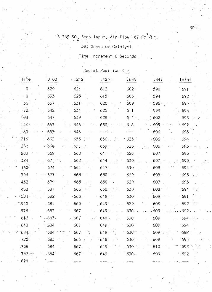
- 3;.36% S02 Step
393
In p u t, A i r Flow 167
Grams o f C a ta ly s t
F t3/H r .
Time 1ncrement 6 Seconds
Radial. P o s it io n ( r )
- :
Time 0.00 .212 .423 .685 .847 1 n 1 e"
0 629 621 612 602 590 691
o . 633 625 615 605 ' . 594 692
36 : 637 631 620 • :. 609 596 . 693
72 . 642 . 634 625 61 1 599 693
108 647 639 628 614 : 602 693
144 , 653 643 630 618 • 605 692
TOO. 657 = 648 . . . ---- ; 606 693
216 662 653 636 625 606 . 694
252 666 . . : .657 ' ' 639 . 626 ■ 606 ■ 693
288. 669 , 660 641 . 628 ■ 607 693
324 671 . 6.62 . 644. 630 ... . . .. 607 . 693
360 ;■ 674 664 647 630 ’ 608 ' 694
396 • 677 ' 665 " 650 629 608 693
432 679 . 665 650 629 607 . , 693
468 681 666 650 :: . 630 608 694
504 682 666 649 630 - 609 691
540 : . 681 . 665 . . ...... 649 • • 629 608 692
576 - 683 . - " 667 '... . 649 • - - 630 • 609 692
612 • 683 667 • 648 - 630 • 609 • 694
648 684 ■ 667 649 : 630 609 694
684 684 " 667 649 630 609 ' r, 692
720;: 683 666 " 648• ■ 630 609 693
756 684 ' 667 649 630 ' 610 ■ 693
792 ' 684 : 667 ' 649 630 609 692
828 .■ . . . . .
61
3.36% S02 Step In p u t , A i r Flow 167 F t 3/ H r .
262 Grams o f C a ta l y s t
Time Increm erit 6 Seconds
R adia l P o s it io n
tim e 0.00 , .212 .423 .685 .847 : In le t
0 631 620 610 592 586 690
0 632 623 613 596 589 691
36 ' „ 641 630 • 618 Y 602 593 • 691
72 . . — - . 634 V 623 606 - 596 ■ 692 '
108 648 ' • 640 / / 627 612 601 ' 692
144 652 643 631 ' : 692
180 657 " 650 " 636 621 605 693
21 6 660 653 638 622 605 •: 693
252 ■ 666 657 . ■■642 ■ ' 623 ' 609 691
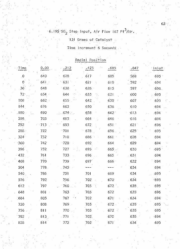
6.19% SC^ Step In p u t, A i r Flow 167 F t^ /H r .
131 Grams o f Cata Iy s t •
Time Increm ent 6 Seconds
R adia l P o s it io n
T i me 0.00 .212 .423 .685 .847 1 n 1 e t
0 640 . 628 . . 617 605 588 695
0 . 641 631 621 ’ 610 592 694
36 648 638 626 615 597 696
n 654 644 v. 633 : 621 600 695
108 662 • 655 : 642 630 607 695
144 676 663 650 636 610 694
180 690 . : • 674 . 658 642 613 . 694
216; 703 683 664 ' 646 616 694
252 • 713 693 672 651 621 696
288 722 701 678 656 : 625 695
324 732 710 686 661 628 694
360 742 720 692 664 629 694
396 752 727 ; 695 665 630 695
432 761 733 . 696 665 631 694
468 770 739 697 666 632 694
504 778 745 ----- 634 694
540 786 751 701 669 634 . 695
576 . 792 756 702 670 634 695
612 797 .. 760 : 703 V 672 635 695
648 801 763 703 672 635 696
684 805 767 702 671 " . 634 694
720 808 769 703 672 635 . 695
756 . ' 81 1 770 703 : 672 635 695
792 8 ,3 771 702 670 635 694
828 814 772 702 671 634 695
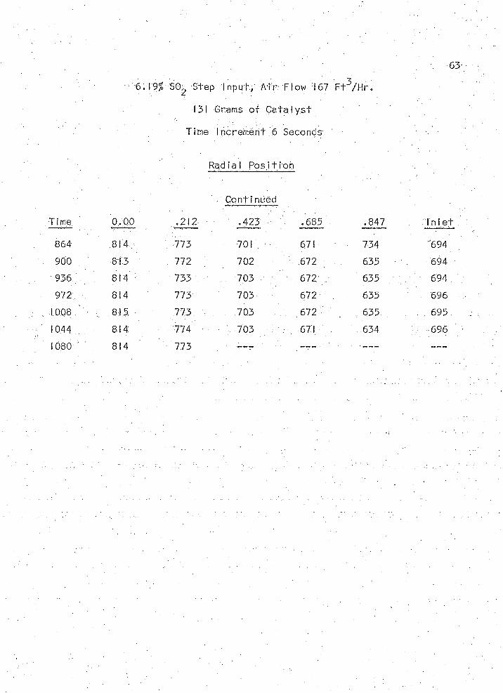
63
6.19/! 50^ Step I n p u t . A i r Flow i 67 F t ^ / H r .
131 Grams o f C a ta l y s t
Time Increm ent 6 Seconds
Rad la I P o s it io n
,' Cont i nued
Tima 0,00 .212 ,423 .685 .847 ; In le i
864 814, 773 . 701 671 734 "694
900 , 813 , 772 702 672 635 694
936/: 814 733 V .... 703 672 635 ' ; 694
972; 814 773 703 672 635 696
1008 / , 815 ' 773 : 703 672 . , 635 : . 695
1044 814 774 703 . 671 634 696
1080 814 773 — ~ > ■ — ---
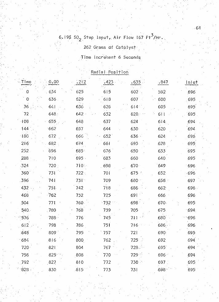
64
6 .19$ SC> 2 Step In p u t , . A i r Flow 167 F t ^ / H r . ..
262 Grams o f C a ta l y s t
Time Increm ent 6 Seconds
Radia l P o s it io n
Time .0.00 .212 .423 .635 .847 In le t
.0 : ■ 634 - . 625 615 602 592 .696.
0 636. . 629 . 618 607 600 695
-36;,:,.:-. :. 64.1 636 626 614 605 695
72 648 642 632 620 61 1 . 695
108 655 648 637 624 614 . 694
144 662 657 . 644 630 620 694
ISO • 672 666 652 636 - 624 696
216 682 674 661 693 628 695
252 • 696 685 676 650 V 633 695
288 . 710 695 683 660 640 695
324 720 710 698 670 649 696
360 - 731 722 701 675 \ 652 696
396 . 741 731 709 680 656 697
.432. 751 742 718 686 662 696
468 762 752 725 691 666 696
504 771 . 760 732 698 670 695
540. 780 - 768 739 705 675 694
576 788 776 745 711 680 696
612 ... 798 786 751 716 686 696
648 809 795 . 757 721 690 695
684 816 800 762 .. : 725 c 692 694
720 821 804 767 728 695 694
756 825 808 770 729 696 , 694
792 827 810 . 772 730 697 695
828 - 830 815 773 731 698 695
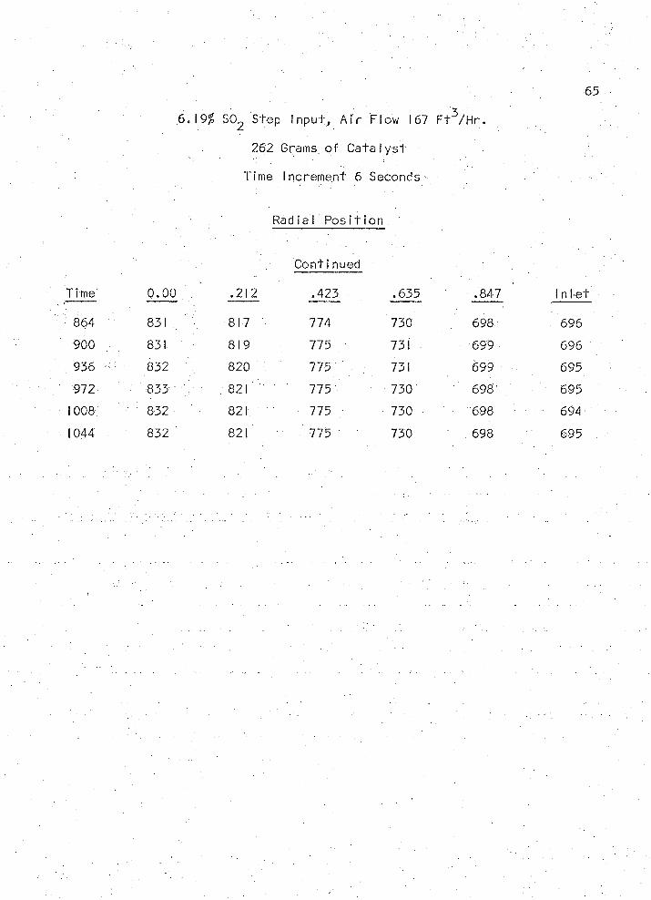
65
6.19% S02 Step In p u t , A i r .Flow 167 F t ^ /H r .
262 Grams, o f C a ta l y s t
Time Increm ent 6 Seconds
Rad la I P o s it io n
C onti nued
Time 0.00 .212 .423 .635 : .847 1 n 1 e t
'8 6 4 831 817 774 730 698 696
900 ... 831 819 775 731 • 699 696
. 936 — 832 820 775 731 699 695
972 833 .821 775 730 698- . 695
1008 832 821 775 730 698 694' :
1044 832 821 775 730 698 695
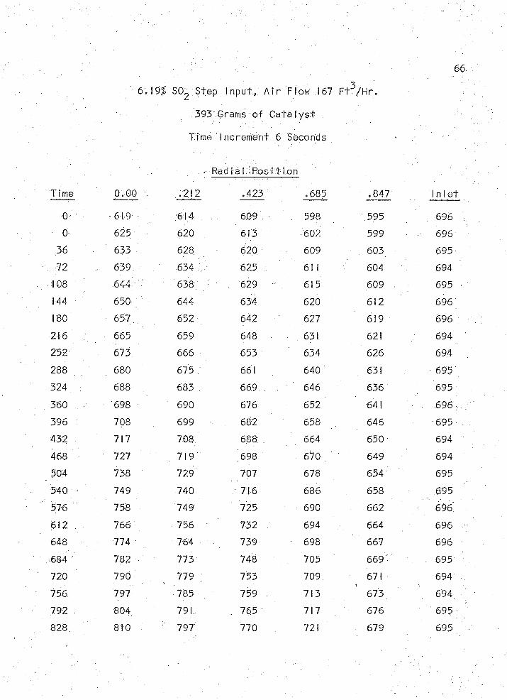
6.19$ SOg Step I n p u t , . A i r Flow .167 F t ^ / H r .
393 Grams o f C a ta ly s t
Time Increm ent 6 Seconds
■ Radia l P o s it io n
T i me 0.00 . . .212 .423 .685 .847 In 1 e t
0 - 61.9 614 . 609 598 .595 696
0 625 620 613 602 599 696
36 633 628 620. 609 603 695
72 639 634 ' 625 61 1 604 694
'108 644 ' 638 629 615 609 . 695
144 650 644 634 620 612 696
180 657. 652 642 627 619 696
216 665 659 648 ■ 631 621 694
252 673. 666 653 634 626 .694
288 680 675 661 640 631 695
324 688 683 . 669. . 646 636 695
360 ... • 69.8 690 676 652 641 ' .696 ,
396 ; 708 699 . 682 658 646 695
432 717 708 688 664 650 694
468 727 719 '698 670 649 694
504 738 729 707 678 654 695
540 749 740 . 7:16 686 658 695
576 758 749 725 690 662 696
612 . 766 756 732 . 694 664 696
648 774 764 739 698 667 696
.684 782 773 748 705 669 695
720 790 779 753 709 671 694 '
756. 797 785 759 . 713 673 694.
792 804 791: . . 7 6 5 717 676 695
828 810 ' 797 770 721 679 695
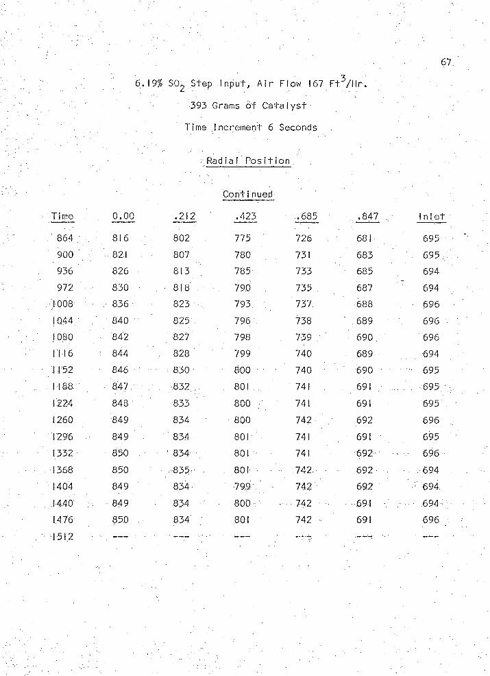
67
6.19% SC> 2 Step In p u t , A i r Flow 167 F t ^ / H r .
393 Grams o f C a ta l y s t
. Time Increm ent 6 Seconds
RadiaI P o s it io n . .
Continued
Time 0.00 .212 .423 .685 . .847 . 1 n le t
864 . 816 802 775 726 681 695
900 821 807 780 731 683 . 695
936 826 8 i3 ; 785 733 685 694
972 830 • 818 790 735 687 \ 694
1008 , 836 823 . 793 . 737 688 696
1044 840 825 796 738 689 696
1080 ■ 842 ' 827 ' 798 . 739 . ■ 690 696 .
1116. ■ 844 . 828 799 740 689 694
1152 846 : 830 800 740 690 695
I 188 847 832 . 801 741 691 695
1224 848 833 800 . 741 691 695
1260 8:49 834 800 742 ' 692 696
1296 849 834 801 741 691 695
1332 850 ■ 834 801 741 692 696
1368 850 • 835 - 801 742 - 692 . 694
1404 849 834 799 742 692 694
1440 ; 849 • 834 800 - 742 691 V , 694
1476 850 834 801 742 691 696
1512 1 ■ ■ ‘
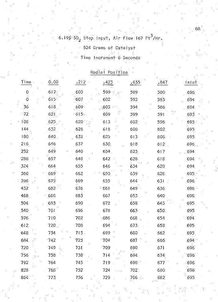
68,
6 . 19^: SQ^ S tep .. 1 n p u t . A i r f l o w 167 F t ^ / H r .
524 Grams o f C a t a l y s t
Time Increm ent 6 Seconds
Rad ia I P o s it io n
Time 0.00 .212 .423 .635 .847 In i e t
0 612 605 - - 599 . 589 580 696.
6 615 607 602 592 583 694
.36 618 609 605 594 586 694
72 621 615 609 ■ 599 591 ; 693
108 625 620 613 602 596 695
144 632 626 618 608 602. 695
180 640 ■ 632 625 613 606 695
216 646 637 630. 618 612 696
252 649 640 634 . 623 617 . 694
288 657 648 . 642 628 618 694
324 ' 664 655 646 634 620 694
360 ' 669 662 650 639 , 626 695
396 675 669 655 644 631 " 696
432 682 676 661 649 636 696
468 ■ 688 683 667 653 640 : 696
504 • 693 690 672 658 645 695
540 701 696 678 663 650 695.
576 710 702 686 668 654 . 694
612 720 \ 708 694 673 658 695
648 ; 734 715 699 680 662 695
684 742 723 704 687 666 694
720 749 v 731 709 690 671 696
756 : 758 738 714 694 674 696
792 . 764 745 719 698 677 696
828 768 752 724 702 680 696
864 773 756 729 . 706 682 695
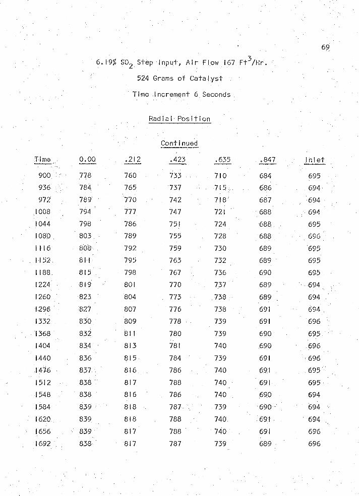
' / 69
6.19% SO2 Step In p u t, A i r Flow 167 F t^ /H r .
524 Grams o f C a ta ly s t
Time Increm ent 6 Seconds
RadlaI P o s it io n
C onti nued
Time 0.00 . .212 .423 .635 .847 Ih le -
900 778 760 . 733 • ; 710 . 684 695
936 784 765 737 715 , . 686 .694
972 . . 789 770 . . 742 718 687 . 694
100.8 794 777 747 721 688 694
1044 798 786 . 751 724 688 695
1080 803 789 755 728 688 696
1116 ■ 808 792 759 730 689 695
1152 811 795 763 732 689 695
1 188 815 798 767 736 690 695
1224 819 801 770 . 737 689 ' 694
1260 823 804 773 738 689 . 694
1296 827 807 : 776 738 691 694
1332 . 830 . 809 778 739 691 696
1368 832 811 780 739 690 695
1404 834 813 781 740 690 . .696
1440 836 815 784 739 691 696
.1476 837 816 . 786 . 740 691 695
1512 838 817 788 740 691 695
1548 / 838 / 816 786 740 690 694
1584 839 818 . 787 739 690 694
1620 839 818 788 740. 691 694
1656 839 817 788 740 691 696
1692 838 817 787 739 689 - 696
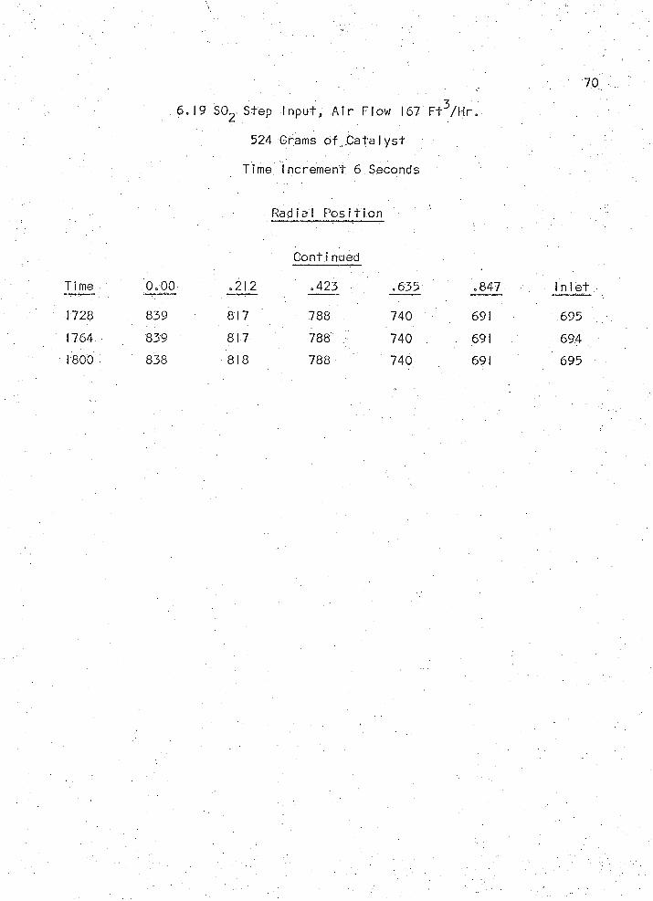
70
6 .1 9 SC> 2 Step In p u t , A i r Flow 167 F t ^ / H r .
524 Grams o f .C a ta ly s t
Time Increm en t 6 Seconds
Radia l P o s it ion
Time 0.00
1728 839
1764 839
1800 838
Continued
.212 .423 •
817 788
817 788
818 788
.635 .847
740 691
740 691
740 691
In le t
695
694
695
REFERENCES
1. P y z e !D a n ie l , M. S. Thesis , U n iv e rs ity o f A rizo n a , Tucson, A rizona(1968).
2. H a ll , R. E. and Sm ith, J . M ., Design o f G as-S o lid C a ta ly t ic R eacto rs ,Chem. Eng. P rb g r . , 4 5 / 7 : 459-470. (1949).
3. D avies, 0. L . , S ta t is t ic a l Methods in Research and P ro d u c tio n , T h irdE d it io n R evised, Hafner P u b lis h in g Company (1961 ).
4. Hougen and .Watson, Chemical Process P ri n c ip ie s , P a rt Three., K in e t ic s :and 'C a ta r ly s t:s> VJohh V/’iriey ■ahd Sons -1 ( I 964).
5. P e rry , J . H.,'-.'Chem ica I Eng in e e rs ’ Handbook", 4 th E d ., M cGraw-H illBook Company, New Y ork: 5 -5 1 (1963 ).
71