Embed Size (px)
Citation preview

Theory and Practice of Geographic Routing
Stefan Ruhrup
Department of Computer ScienceUniversity of Freiburg, Germany
February 2009
Abstract Geographic routing algorithms use position information for makingpacket forwarding decisions. Unlike topological routing algorithms, they do notneed to exchange and maintain routing information and work nearly stateless. Thismakes geographic routing attractive for wireless ad hoc and sensor networks. Mostgeographic routing algorithms use a greedy strategy that tries to approach the des-tination in each step, e.g. by selecting the neighbor closest to the destination as anext hop. However, greedy forwarding fails in local minimum situations, i.e. whenreaching a node that is closer to the destination than all its neighbors. A widelyadopted approach to solve this situations is planar graph routing, which guides thepacket around the local minimum and guarantees delivery, required that a planarsubgraph of the network graph can be constructed. This chapter gives an overviewof the fundamentals of geographic routing, reviews theoretical results and presentsnew developments towards practical applicability.
1 Introduction
Geographic routing (also known as position-based routing or geometric routing) is atechnique to deliver a message to a node in a network over multiple hops by meansof position information. Routing decisions are not based on network addresses androuting tables; instead, messages are routed towards a destination location. Withknowledge of the neighbors’ location, each node can select the next hop neighborthat is closer to the destination, and thus advance towards the destination in eachstep. The fact that neither routing tables nor route discovery activities are necessarymakes geographic routing attractive for dynamic networks such as wireless ad hocand sensor networks. In such networks, acquiring and maintaining routing informa-tion is costly as it involves additional message transmissions that require energy andbandwidth and frequent updates in mobile and dynamic scenarios. In contrast, there
are geographic routing algorithms that work nearly stateless and can provide highmessage delivery rates under mobility. All this applies under the following assump-tions:
1. A node can determine its own position.2. A node is aware of its neighbors’ positions.3. The position of the destination is known.
With GPS or other satellite based navigation systems, position information can bemade available to even small mobile devices. Further location systems for indoorapplications are described in [37]. The second assumption requires broadcasting theposition information locally to other participants in the network. With this infor-mation a node is able to determine the next hop that is closer to the destination. InSection 4 we will see that there are even algorithms that do not need neighborhoodinformation in advance. The third assumption can be met by means of a location ser-vice that maps network addresses to geographic locations. Section 7 reviews someof these approaches. In some cases, the destination is inherently known to the nodes,e.g. in some sensor network applications where a single sink node collects all thedata measurement information.
The main prerequisite to meet the three assumptions is a positioning system.If this is available, geographic routing provides an efficient and scalable solutionfor routing in wireless and mobile networks. However, a simple greedy forwardingby minimizing the distance to the destination location in each step cannot guar-antee message delivery. Nodes usually have a limited transmission range and thusthere are situations where no neighbor is closer to the destination than the nodecurrently holding the message. Greedy algorithms cannot resolve such dead-end orlocal minimum situation. Therefore, recovery methods have been developed, themost prominent of which are based on planar graph routing, where the messageis guided around the local minimum by traversing the edges of a planar subgraphof the network communication graph. Planar graph routing techniques can providedelivery guarantees under certain assumptions, which are explained in Section 3,and complement the efficient greedy forwarding. Altogether, greedy forwarding incombination with a recovery can be considered as state-of-the-art technique in geo-graphic routing.
This chapter gives an overview of geographic routing starting with greedy algo-rithms and recovery strategies in Section 2 and Section 3, covering also theoreticalresults on their efficiency. Section 4 describes contention-based routing, a fully re-active variant of geographic routing, which does not require the neighborhood tobe known in advance. In Section 5 algorithms and methods for geographic routingunder realistic network models are reviewed. Further variants for multicasting andgeocasting are described in Section 6. Section 7 describes methods for providinga location service that allows to look up the destination location. Section 8 givesexamples for the application of geographic routing. Finally, Section 9 concludes thechapter.
2
1.1 Preliminaries
As the basic ideas of geographic routing use geometric criteria, we use the follow-ing concepts to describe wireless networks. An often-used and basic model for suchnetworks is the so-called unit disk graph (UDG) which contains an edge e = (u,v)between two nodes u and v, if |uv| ≤ 1. In other words, assuming a restricted trans-mission range normalized to 1, the links between the nodes of a given node setform a unit disk graph. Unit disk graphs rely on the assumption that transmissionranges are uniform and imply that all links are bidirectional. We will see in Sec-tion 5 how this assumption can be weakened. Nodes within the transmission rangeare connected to the sender and called neighbors.
The network graph will be the basis to describe the routing problem. Routingstarts at the source node s and aims at forwarding a packet to the target node t. Thenode currently holding the packet is called forwarder, possible next hop neighborswithin its transmission range are called candidates.
2 Geographic Greedy Forwarding
The first approaches for geographic routing were developed in the 1980s for packetradio networks [84, 38] and wired networks [19]. These approaches describe localrules used by the forwarding node to select a neighbor as a next hop. As routingdecisions are locally optimal, these approaches are termed greedy forwarding.
2.1 Greedy and Compass Routing
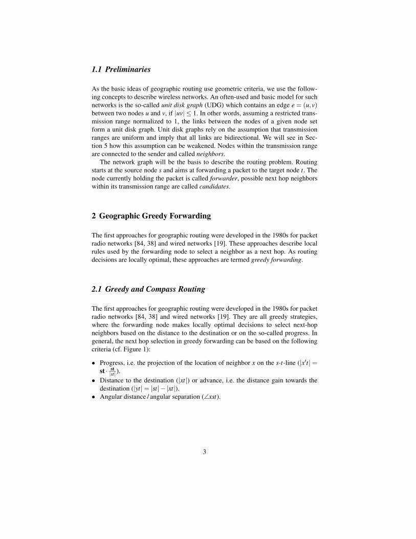
The first approaches for geographic routing were developed in the 1980s for packetradio networks [84, 38] and wired networks [19]. They are all greedy strategies,where the forwarding node makes locally optimal decisions to select next-hopneighbors based on the distance to the destination or on the so-called progress. Ingeneral, the next hop selection in greedy forwarding can be based on the followingcriteria (cf. Figure 1):
• Progress, i.e. the projection of the location of neighbor x on the s-t-line (|x′t| =st · st|st| ).
• Distance to the destination (|xt|) or advance, i.e. the distance gain towards thedestination (|yt|= |st|− |xt|).
• Angular distance / angular separation (∠xst).
3
s t
x
r
x’y
Figure 1: Progress and advance.
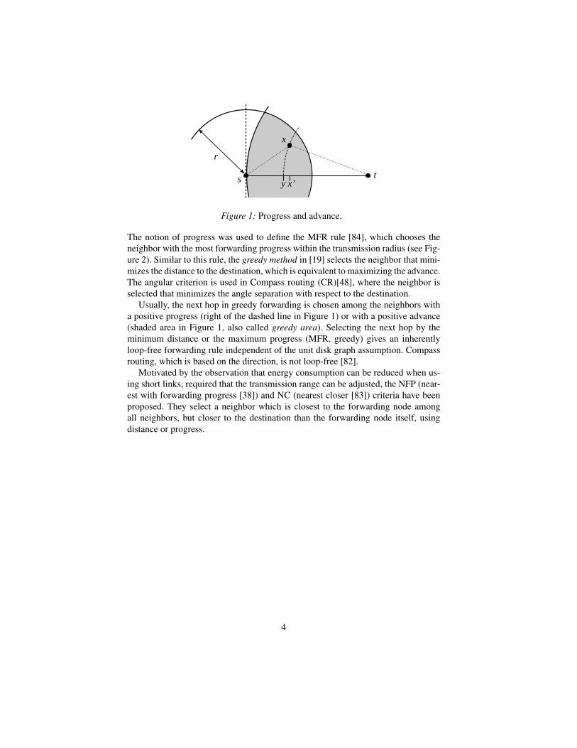
The notion of progress was used to define the MFR rule [84], which chooses theneighbor with the most forwarding progress within the transmission radius (see Fig-ure 2). Similar to this rule, the greedy method in [19] selects the neighbor that mini-mizes the distance to the destination, which is equivalent to maximizing the advance.The angular criterion is used in Compass routing (CR)[48], where the neighbor isselected that minimizes the angle separation with respect to the destination.
Usually, the next hop in greedy forwarding is chosen among the neighbors witha positive progress (right of the dashed line in Figure 1) or with a positive advance(shaded area in Figure 1, also called greedy area). Selecting the next hop by theminimum distance or the maximum progress (MFR, greedy) gives an inherentlyloop-free forwarding rule independent of the unit disk graph assumption. Compassrouting, which is based on the direction, is not loop-free [82].
Motivated by the observation that energy consumption can be reduced when us-ing short links, required that the transmission range can be adjusted, the NFP (near-est with forwarding progress [38]) and NC (nearest closer [83]) criteria have beenproposed. They select a neighbor which is closest to the forwarding node amongall neighbors, but closer to the destination than the forwarding node itself, usingdistance or progress.
4

s t
NFP
MFR
CR
greedyNC
r
Figure 2: Variants of greedy forwarding.
2.2 Advanced Strategies
Greedy forwarding has one important drawback: it fails in local minimum situationswhere the forwarding node has no other neighbors closer to the destination. In somecases, a sophisticated strategy is necessary to recover from this situation; in othercases, a simple backward step is sufficient to be able to resume the greedy strategysuccessfully.
The GEDIR [82] method is such a greedy strategy with backward steps. When-ever a message has reached a local minimum, the packet is sent back to the previoushop, which applies the greedy rule again while excluding previously visited deadend nodes from the selection. This strategy is also loop-free.
Further improvements of the basic strategies Greedy, MFR and CR can beachieved if 2-hop information is available [82]. In this case, the forwarder selectsa suitable neighbor out of the 2-hop neighborhood and forwards the packet to thedirect neighbor that is connected to the selected node. Note, that 2-hop informationhas to be distributed, which requires a higher message overhead.
A greedy-based algorithm that goes beyond using 2-hop information is SPEED[34], which is designed to increase the relay speed. It uses an additional “backpres-sure” heuristic to avoid congested areas and void regions. The protocol relies onbeaconing, extended by on-demand beacons for delay estimation and backpressureinformation. The forwarding works as follows: Nodes from the greedy area, whoserelay speed is above a certain threshold, are selected probabilistically. The higherthe relay speed the higher the probability to be selected. If no neighbor meets therelay speed requirement, the node drops the packet with a certain probability thatdepends on the failure ratio of packet forwarding to the neighbors. The necessaryinformation to derive the failure ratio is gained from the neighbors by backpressure
5
beacons, which are sent in case of congestion or in a local minimum situation. Thismethod can alleviate local minima problems in case of small void regions, but itcannot guarantee delivery in general.
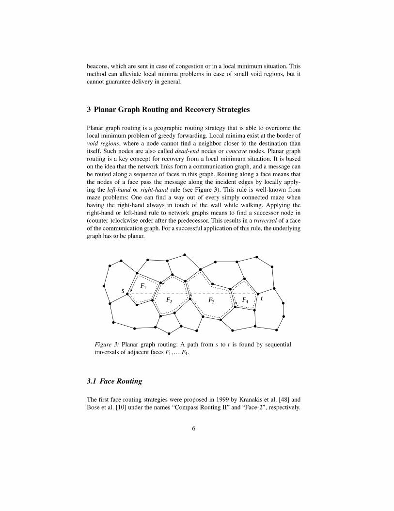
3 Planar Graph Routing and Recovery Strategies
Planar graph routing is a geographic routing strategy that is able to overcome thelocal minimum problem of greedy forwarding. Local minima exist at the border ofvoid regions, where a node cannot find a neighbor closer to the destination thanitself. Such nodes are also called dead-end nodes or concave nodes. Planar graphrouting is a key concept for recovery from a local minimum situation. It is basedon the idea that the network links form a communication graph, and a message canbe routed along a sequence of faces in this graph. Routing along a face means thatthe nodes of a face pass the message along the incident edges by locally apply-ing the left-hand or right-hand rule (see Figure 3). This rule is well-known frommaze problems: One can find a way out of every simply connected maze whenhaving the right-hand always in touch of the wall while walking. Applying theright-hand or left-hand rule to network graphs means to find a successor node in(counter-)clockwise order after the predecessor. This results in a traversal of a faceof the communication graph. For a successful application of this rule, the underlyinggraph has to be planar.
st
F1
F2 F3 F4
Figure 3: Planar graph routing: A path from s to t is found by sequentialtraversals of adjacent faces F1, ...,F4.
3.1 Face Routing
The first face routing strategies were proposed in 1999 by Kranakis et al. [48] andBose et al. [10] under the names “Compass Routing II” and “Face-2”, respectively.
6
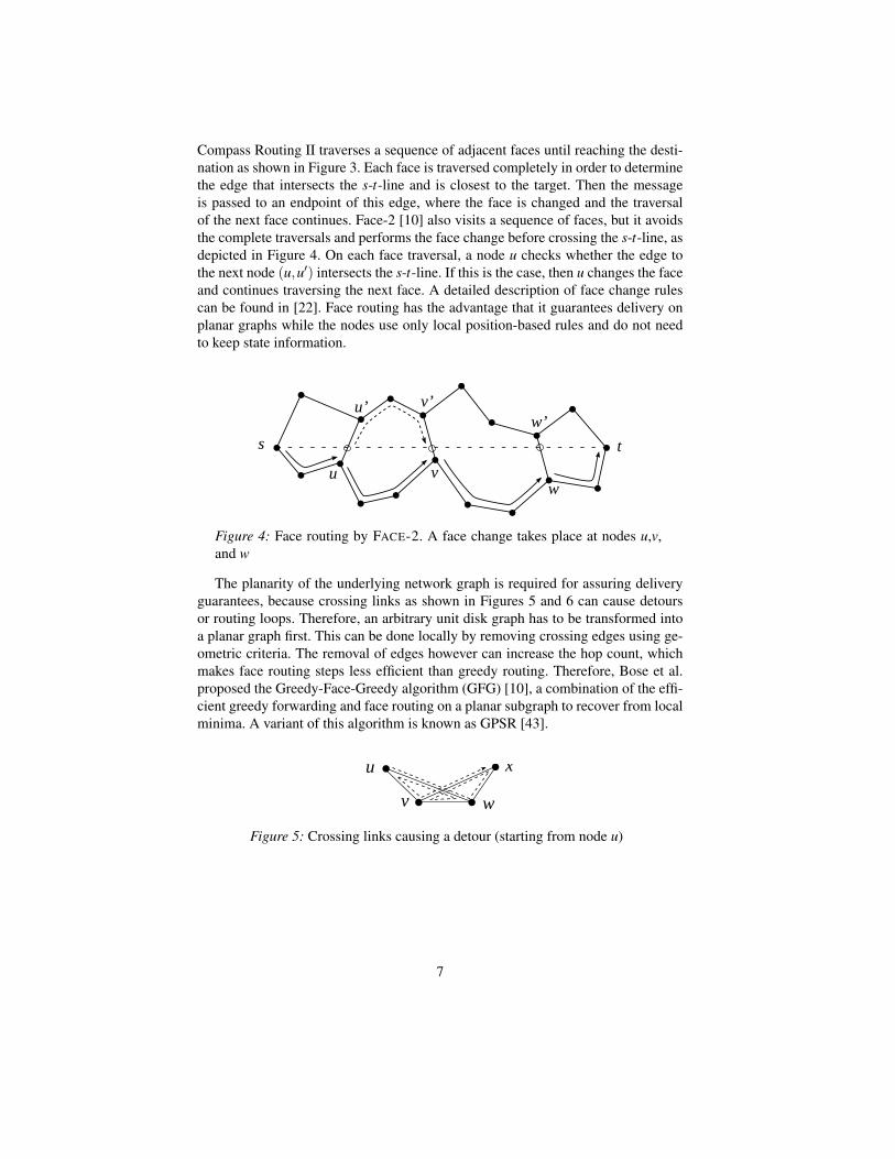
Compass Routing II traverses a sequence of adjacent faces until reaching the desti-nation as shown in Figure 3. Each face is traversed completely in order to determinethe edge that intersects the s-t-line and is closest to the target. Then the messageis passed to an endpoint of this edge, where the face is changed and the traversalof the next face continues. Face-2 [10] also visits a sequence of faces, but it avoidsthe complete traversals and performs the face change before crossing the s-t-line, asdepicted in Figure 4. On each face traversal, a node u checks whether the edge tothe next node (u,u′) intersects the s-t-line. If this is the case, then u changes the faceand continues traversing the next face. A detailed description of face change rulescan be found in [22]. Face routing has the advantage that it guarantees delivery onplanar graphs while the nodes use only local position-based rules and do not needto keep state information.
s t
vuw
v’u’w’
Figure 4: Face routing by FACE-2. A face change takes place at nodes u,v,and w
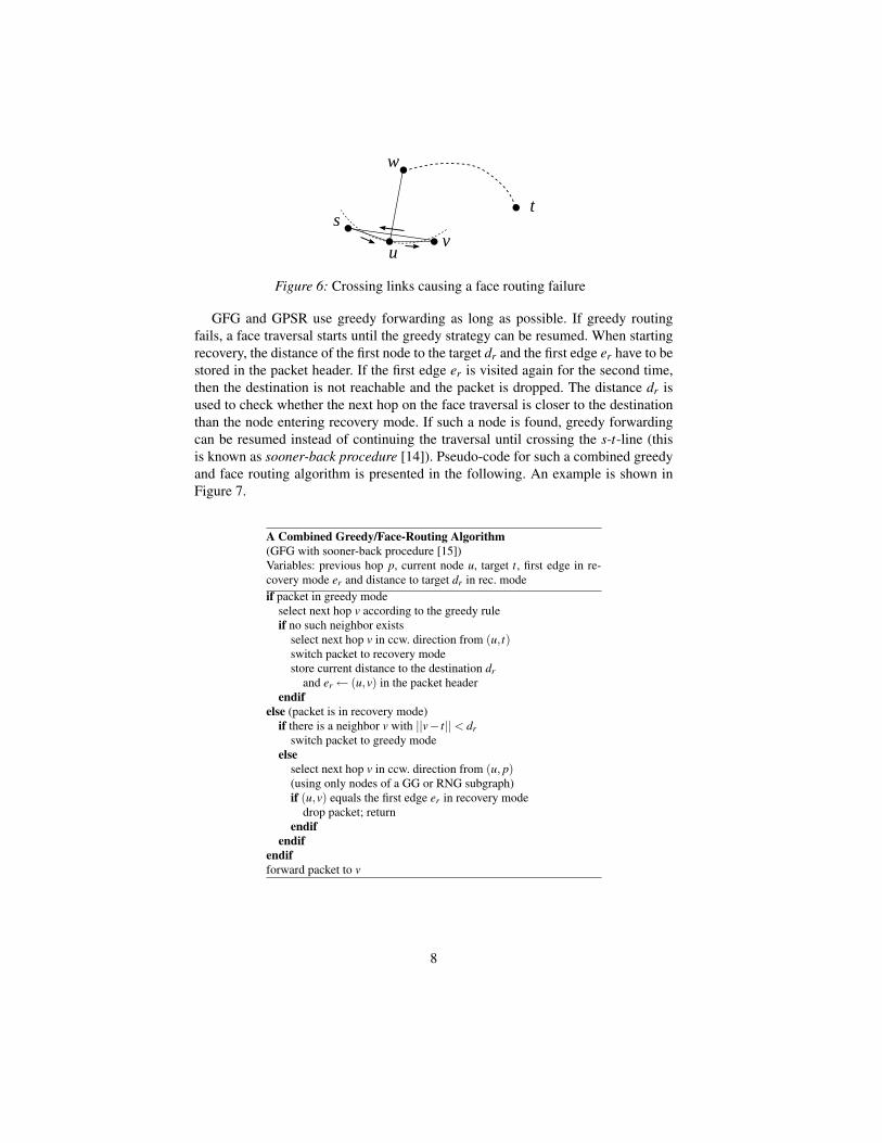
The planarity of the underlying network graph is required for assuring deliveryguarantees, because crossing links as shown in Figures 5 and 6 can cause detoursor routing loops. Therefore, an arbitrary unit disk graph has to be transformed intoa planar graph first. This can be done locally by removing crossing edges using ge-ometric criteria. The removal of edges however can increase the hop count, whichmakes face routing steps less efficient than greedy routing. Therefore, Bose et al.proposed the Greedy-Face-Greedy algorithm (GFG) [10], a combination of the effi-cient greedy forwarding and face routing on a planar subgraph to recover from localminima. A variant of this algorithm is known as GPSR [43].
xu
v w
Figure 5: Crossing links causing a detour (starting from node u)
7
s
uv
w
t
Figure 6: Crossing links causing a face routing failure
GFG and GPSR use greedy forwarding as long as possible. If greedy routingfails, a face traversal starts until the greedy strategy can be resumed. When startingrecovery, the distance of the first node to the target dr and the first edge er have to bestored in the packet header. If the first edge er is visited again for the second time,then the destination is not reachable and the packet is dropped. The distance dr isused to check whether the next hop on the face traversal is closer to the destinationthan the node entering recovery mode. If such a node is found, greedy forwardingcan be resumed instead of continuing the traversal until crossing the s-t-line (thisis known as sooner-back procedure [14]). Pseudo-code for such a combined greedyand face routing algorithm is presented in the following. An example is shown inFigure 7.
A Combined Greedy/Face-Routing Algorithm(GFG with sooner-back procedure [15])Variables: previous hop p, current node u, target t, first edge in re-covery mode er and distance to target dr in rec. modeif packet in greedy mode
select next hop v according to the greedy ruleif no such neighbor exists
select next hop v in ccw. direction from (u, t)switch packet to recovery modestore current distance to the destination dr
and er ← (u,v) in the packet headerendif
else (packet is in recovery mode)if there is a neighbor v with ||v− t||< dr
switch packet to greedy modeelse
select next hop v in ccw. direction from (u, p)(using only nodes of a GG or RNG subgraph)if (u,v) equals the first edge er in recovery mode
drop packet; returnendif
endifendifforward packet to v
8
s tu
w
xv
Figure 7: Combined greedy/face routing: After reaching local minimum u ingreedy mode (dashed arrow), a face traversal is started (solid arrow) until anode v is found that is closer to the target than u.
When using such combined algorithms, the greedy part can be performed using alllinks of the unit disk graph, while face routing needs a local planar subgraph. Wewill see in the next section how a planar subgraph can be constructed.
3.2 Planarization
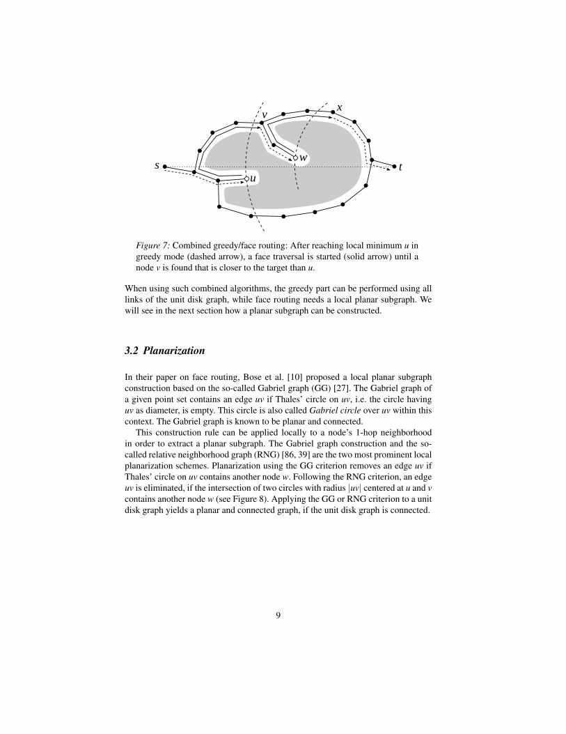
In their paper on face routing, Bose et al. [10] proposed a local planar subgraphconstruction based on the so-called Gabriel graph (GG) [27]. The Gabriel graph ofa given point set contains an edge uv if Thales’ circle on uv, i.e. the circle havinguv as diameter, is empty. This circle is also called Gabriel circle over uv within thiscontext. The Gabriel graph is known to be planar and connected.
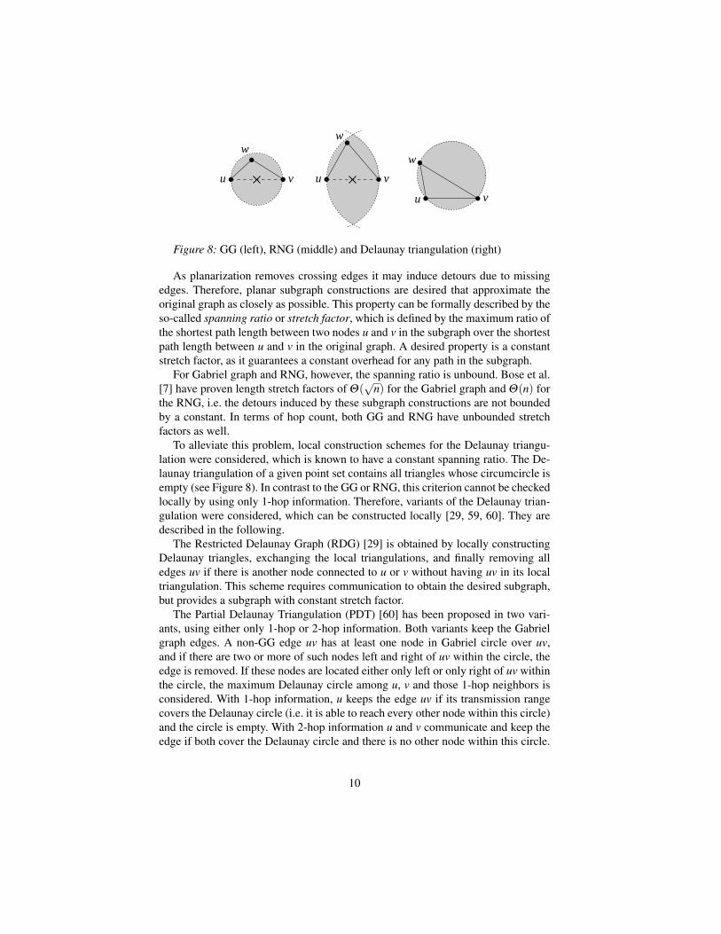
This construction rule can be applied locally to a node’s 1-hop neighborhoodin order to extract a planar subgraph. The Gabriel graph construction and the so-called relative neighborhood graph (RNG) [86, 39] are the two most prominent localplanarization schemes. Planarization using the GG criterion removes an edge uv ifThales’ circle on uv contains another node w. Following the RNG criterion, an edgeuv is eliminated, if the intersection of two circles with radius |uv| centered at u and vcontains another node w (see Figure 8). Applying the GG or RNG criterion to a unitdisk graph yields a planar and connected graph, if the unit disk graph is connected.
9
u v
w
u v
w
u v
w
Figure 8: GG (left), RNG (middle) and Delaunay triangulation (right)
As planarization removes crossing edges it may induce detours due to missingedges. Therefore, planar subgraph constructions are desired that approximate theoriginal graph as closely as possible. This property can be formally described by theso-called spanning ratio or stretch factor, which is defined by the maximum ratio ofthe shortest path length between two nodes u and v in the subgraph over the shortestpath length between u and v in the original graph. A desired property is a constantstretch factor, as it guarantees a constant overhead for any path in the subgraph.
For Gabriel graph and RNG, however, the spanning ratio is unbound. Bose et al.[7] have proven length stretch factors of Θ(
√n) for the Gabriel graph and Θ(n) for
the RNG, i.e. the detours induced by these subgraph constructions are not boundedby a constant. In terms of hop count, both GG and RNG have unbounded stretchfactors as well.
To alleviate this problem, local construction schemes for the Delaunay triangu-lation were considered, which is known to have a constant spanning ratio. The De-launay triangulation of a given point set contains all triangles whose circumcircle isempty (see Figure 8). In contrast to the GG or RNG, this criterion cannot be checkedlocally by using only 1-hop information. Therefore, variants of the Delaunay trian-gulation were considered, which can be constructed locally [29, 59, 60]. They aredescribed in the following.
The Restricted Delaunay Graph (RDG) [29] is obtained by locally constructingDelaunay triangles, exchanging the local triangulations, and finally removing alledges uv if there is another node connected to u or v without having uv in its localtriangulation. This scheme requires communication to obtain the desired subgraph,but provides a subgraph with constant stretch factor.
The Partial Delaunay Triangulation (PDT) [60] has been proposed in two vari-ants, using either only 1-hop or 2-hop information. Both variants keep the Gabrielgraph edges. A non-GG edge uv has at least one node in Gabriel circle over uv,and if there are two or more of such nodes left and right of uv within the circle, theedge is removed. If these nodes are located either only left or only right of uv withinthe circle, the maximum Delaunay circle among u, v and those 1-hop neighbors isconsidered. With 1-hop information, u keeps the edge uv if its transmission rangecovers the Delaunay circle (i.e. it is able to reach every other node within this circle)and the circle is empty. With 2-hop information u and v communicate and keep theedge if both cover the Delaunay circle and there is no other node within this circle.
10

The PDT scheme reduces the communication cost compared to the RDG, but it isunknown whether it can provide a constant factor spanner.
A localized reactive approach to planar subgraph construction has been presentedin [21], which is called Direct Planarization. Direct planarization checks edges ex-plicitly for possible edge intersections before they are used by the routing algorithmand decides in case of an intersection, which edge has to be removed. Two criteriawere proposed, based on angle and Delaunay circles. Using the angle-based directplanarization (ADP), an edge uv is preferred over an intersecting edge wx, if either∠xuw or ∠wvx is the maximum angle in the quadrilateral uwvx (see Figure 9). TheDelaunay-based direct planarization (DDP) favors an edge uv over wx, if x is notcontained in the circumcircle of uvw.
Figure 9: Angle-based and Delaunay-based direct planarization
Note that all the planarization criteria presented in this section rely on the unitdisk graph assumption and bidirectional links. Problems of planar graph routing innon-unit disk graphs and possible solutions are described in Section 5.3.
3.3 Improved Planar Graph Routing
Though planar graph routing works stateless and uses local information only, it hastwo disadvantages: first, the construction of a planar subgraph removes edges andmay increase the hop count. Second, a wrong choice of the traversal direction canlead to a long detour in the network.
The first problem is due to the planar subgraph construction. Planarizationschemes such as the Gabriel subgraph construction remove long edges in favorof short ones, which results in an increased hop count when traversing a face ofthe resulting subgraph. This problem can be alleviated, if more information of theneighborhood is available. With 2-hop information, the forwarder can determine thelocal planar subgraph of its neighbors. Thus, instead of following the face traversalhop by hop, one can determine more next hops in advance and use shortcuts to thelast predicted hop [14].
The Greedy Path Vector Face Routing (GPVFR) [57] is also based on the ideato exploit multi-hop information in order to broaden the horizon for forwardingdecisions. GPVFR distributes information among the nodes of the same face. If
11
greedy forwarding fails, a node might know another node on the same face beingcloser to the destination. Then this node is chosen as an intermediate target, whichcan be reached by face routing, even if the complete information about the currentface is not given.
Another technique to reduce the detour on a planar subgraph is to use the nodesof a connected dominating set [14, 1]. In a dominating set, each node is either partof the set, or adjacent to such node. A connected dominating set can be constructedlocally using only position information of the 1-hop neighborhood. Then, the planarsubgraph construction and the face traversal is performed on the internal nodes ofthe dominating set only, which usually leads to a better subgraph than obtained byplanarization of the original network graph. It was shown by Datta et al. [14] thatusing shortcuts and internal nodes of the dominating set can effectively reduce thehop count of face routing or GFG. Especially the use of internal nodes contributessignificantly to a hop count reduction while requiring only 1-hop information fordetermining the internal node status.
Geographic clustering can also reduce the complexity of the underlying topology.Nodes can be grouped into clusters that are defined by geographic areas. In [70] thenodes are mapped onto a grid of quadratic cluster areas. This grid structure providesthe planarity property implicitly and can be used for a virtual routing along gridcells. In [20] the unit disk graph is first planarized using the Gabriel graph criterion.Afterwards a clustering into hexagonal areas is applied. These clusters are the basisfor a cluster graph, which contains an edge between two clusters, if nodes within therespective hexagonal cells are connected. The cluster graph is planar and providesthe basis for face routing. The advantage of geographic clustering is that a facerouting algorithm has the freedom of choice among the nodes within a cluster. It isalso more robust in mobile scenarios, because the resulting graph does not changeuntil a cluster cell changes is entered by a first node or left by the last node, i.e. itchanges its status.
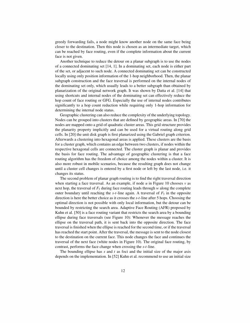
The second problem of planar graph routing is to find the right traversal directionwhen starting a face traversal. As an example, if node u in Figure 10 chooses v asnext hop, the traversal of F3 during face routing leads through w along the completeouter boundary until reaching the s-t-line again. A traversal of F3 in the oppositedirection is here the better choice as it crosses the s-t-line after 5 hops. Choosing theoptimal direction is not possible with only local information, but the detour can bebounded by restricting the search area. Adaptive Face Routing (AFR) proposed byKuhn et al. [50] is a face routing variant that restricts the search area by a boundingellipse during face traversals (see Figure 10): Whenever the message reaches theellipse on the traversal path, it is sent back into the opposite direction. The facetraversal is finished when the ellipse is reached for the second time, or if the traversalhas reached the start point. After the traversal, the message is sent to the node closestto the destination on the current face. This node changes the face and continues thetraversal of the next face (white nodes in Figure 10). The original face routing, bycontrast, performs the face change when crossing the s-t-line.
The bounding ellipse has s and t as foci and the initial size of the major axisdepends on the implementation. In [52] Kuhn et al. recommend to use an initial size
12
of the major axis of 1.2 |st| and an enlargement factor of√
2. If there is no pathto the target within the bounding ellipse, the size of the ellipse is doubled and thesource starts face routing again.
AFR can be used on its own or as as a recovery strategy in combination withgreedy forwarding. This combination is called Greedy Other Adaptive Face Rout-ing (GOAFR) [52]. A further improvement of this algorithm, called GOAFR+ ispresented in [49]. It employs method other than the bounding ellipse to restrict thesearch area, namely a circle centered at the destination, which initially containsthe source node and is gradually reduced when the packet approaches the target.Furthermore, GOAFR+ uses an early fallback strategy to leave the recovery modesooner to resume greedy forwarding. In contrast to the sooner back procedure, whichleaves greedy mode as soon as the distance to the destination is decreased since en-tering face routing mode, GOAFR+ uses the following criterion: It maintains twocounters for the nodes on the traversal that are closer and for those that are not closerto the destination than the start node of the traversal. If the number of nodes closerto the destination exceeds the rest of the nodes on the traversal by a certain factor,the traversal is stopped and the message is passed to the node that is closest to thedestination among the visited nodes and greedy forwarding is resumed. The use ofthe two counters avoids multiple traversals of nodes that were already participat-ing in a traversal before. Through this strategy the algorithm retains its asymptoticefficiency. An overview of AFR and its variants is given in [52].
st
F1
F2F3
F4
u
v
w
xy
Figure 10: Adaptive Face Routing (AFR) [52]. Faces are traversed com-pletely while the search area is restricted by a bounding ellipse.
3.4 Recovery beyond Planarization
Recovery from local minima does not necessarily require creating a planar subgraphprior to routing. One approach is to identify possible local minima beforehand, suchthat a path around a void region is already established when a packet in greedy modearrives at a dead-end node. For this purpose Fang et al. [16] propose the Bound-
13

Hole algorithm, that identifies so-called stuck nodes by applying geometric ruleslocally. Stuck nodes are located on the border of a void region. They are not dead-end nodes in general, but for some specific target locations they are local minima.The void region can be identified then by communication among the stuck nodes.The BoundHole algorithm can be used in conjunction with a combined greedy andface routing algorithm. When reaching a local minimum, the face routing part canuse the pre-computed information about the border of a void region and immediatelyselect the shorter path around this region. This yields shorter paths at the expense ofan additional communication overhead for the communication among stuck nodes.
A similar idea led to the NEAR algorithm [2] that assigns virtual coordinates tonodes in a dead-end region. These coordinates are called elevation values and basedon the angle between a node and its neighbors. Elevated nodes are avoided by therouting algorithm. A typical situation where high elevation values are assigned is a“peninsula” of nodes which extends into a void region. The nodes in this dead-endregion are elevated successively such that the dead-end region is predictable beforeentering it. This mechanism is complemented by a void identification algorithm thatis started by the nodes at the border of a void region. Thus the perimeter informationis available beforehand and can be used to find shorter routes around void region.
Another approach for identifying the boundary of void regions is presented in[63] as part of the Greedy Anti-void Routing (GAR) routing algorithm. Here, theidea for the boundary traversal is to roll a ball whose diameter is the transmissionrange along the nodes on the boundary of a void region. The next node v that ishit by the ball satisfies that the edge from the previous node u is not intersected byanother edge having one endpoint neither connected to u nor v. Thus, it is ensuredthat no important edge on the traversal is missed. The algorithm establishes pointersalong the traversal direction which are used to circumvent void regions.
The described techniques are based on geometric criteria to identify possibledead-end nodes. There are further recovery techniques that do not require a unitdisk graph. One of the underlying concept is an identification of crossing links orpaths around void regions by graph traversals. These approaches are described inSection 5.3 on recovery in non-unit disk graphs.
3.5 Delivery Guarantees and Asymptotic Efficiency
The prominent geographic routing algorithms GFG, GPSR and GOAFR+ have beensubject to simulative studies as well as to theoretical considerations. All three al-gorithms guarantee delivery on GG or RNG subgraphs, which can be constructedlocally under the unit disk graph assumption. GFG provides this delivery guaranteeeven on any planar graph. Frey and Stojmenovic showed that the delivery guaran-tees on GG and RNG are due to a structural graph property of these graphs [22]. InGG and RNG there is always an edge intersecting the s-t-line having one endpointcloser to the target t than the source s, and this implies that a face traversal alwaysfinds a node closer to the target.
14
The performance of the aforementioned geographic routing algorithms dependsmainly on the face routing part. Like in all combined greedy/face routing algorithms,the face routing part is needed to find paths around void regions and the resultingdetours significantly influence the performance. Consider a face traversal starting atnode u in Figure 10 as an example: Turning left at this point is obviously the shorterpath to the target, while turning right leads along the boundary of the network whichcan result in an arbitrarily long detour. An efficient algorithm finds a path whoselength is close to the optimal path length. Therefore, the efficiency is described withrespect to the shortest path length or, more generally, to the optimal cost. This isalso termed a competitive measure.
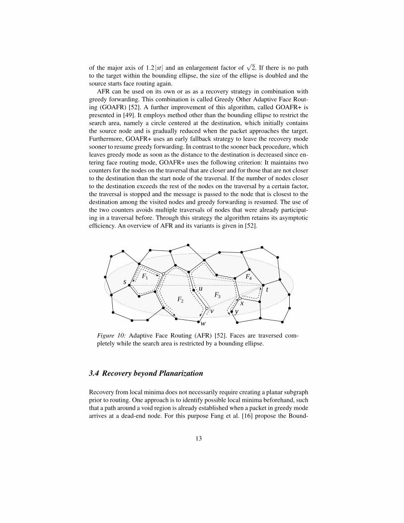
In situations as shown in Figure 10, where a traversal can lead along the networkboundary, GFG and GPSR produce worst-case paths that cannot be bounded by afunction of the shortest path length. A bounded detour can be achieved by the bound-ing ellipse technique, which was introduced in Adaptive Face Routing [50] and usedfor GOAFR and its variants. Kuhn et al. showed that AFR finds a path of cost O(c2)in the worst case, where c is the cost of the optimal path. The quadratic boundis obtained because the detour is limited by the area of the bounding ellipse anddoubling the ellipse does not affect the asymptotic complexity. For this cost boundit is required that the minimum distance between any two nodes is bounded by aconstant, which is called Ω(1)-model. The GOAFR+ algorithm, which in additionperforms greedy routing, has the same asymptotic efficiency. Kuhn et al. also provethat there is a quadratic lower bound on the cost. Therefore, AFR and GOAFR+ areasymptotically optimal.
The lower bound construction from [50] is depicted in Figure 11. It consists of2k nodes on a ring that are just able to reach each other. Every second node onthis ring is attached to a chain of Θ(k) nodes pointing towards the center. Only oneof these chains leads to the target. In this graph any deterministic or randomizedgeographic routing algorithm needs to explore at least half of the dead-end chainsin the (expected) worst case, before finding the target. This results in a path cost ofO(k2) while the shortest path cost is O(k).
s t
Figure 11: Lower bound construction for geographic routing algorithms [50]
15
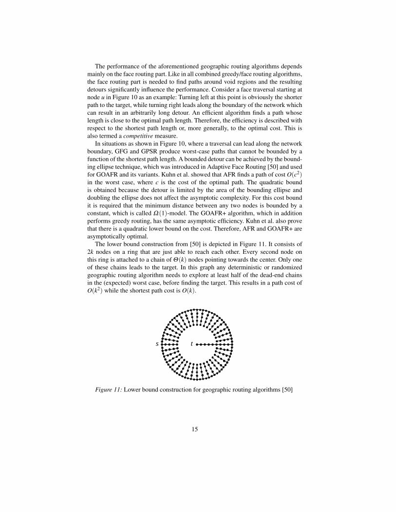
This lower bound holds for any randomized or deterministic geographic routingalgorithm. A similar lower bound holds for greedy algorithms only. Greedy algo-rithms cannot guarantee delivery in the worst case, but if there is a greedy path, itis not even close to the optimal path in the worst case. Considering the graph inFigure 12, a greedy choice based on distance minimization leads from s to node vthat is closer to the target. The path from v to t brings the message closer to the tar-get in each step, but its length is quadratic in the length of the optimal path, whichleads from s through u to t. Thus, for distance-based greedy forwarding, there is aquadratic lower bound with respect to the shortest path length [29].
Figure 12: Lower bound for greedy forwarding [29]
Considering the hop count metric, the quadratic lower bound for geographic rout-ing implies that a quadratic number of messages is needed. This bound on the mes-sage complexity can be reached by a flooding algorithm. Actually, flooding visitsall nodes in the network, but it can be limited by a doubling technique that repeatsrestricted flooding while doubling the hop limit. This technique is also known asexpanding ring search [41] and has a quadratic message complexity. The quadraticlower bound, which is defined in terms of the shortest path, suggests that geographicrouting strategies have the same worst case message complexity than flooding algo-rithms, while flooding algorithms are obviously faster.
In fact, geographic routing is not as inefficient in the worst case as it seems.We have seen that the difficulty of the geographic routing problem depends on thevoid regions which are local minima to a greedy strategy and require a traversal.Following the rationale in [5], one can show that in the worst case the traversal ofvoid regions is unavoidable. Thus, there is a lower bound on hop count and messagecomplexity of Ω(d+ p) for geographic single-path strategies, where d is the shortestpath length and p the perimeter of void regions. This analysis uses an abstractionfrom the geometric issues connected with the problem of void identification andgraph planarization: By a geographic clustering technique [70], a unit disk graph canbe represented by a grid with usable and defective regions. This way the geographicrouting problem on unit disk graphs can be transformed to the problem of routingon a defective grid with only local information. It inherently provides a minimumdistance property as defined in the Ω(1)-model.
16
The lower bound graph in Figure 11 states a special case of the generalized lowerbound of Ω(d + p) with p = Θ(d2), i.e. having a total perimeter length that isquadratic in the shortest path length. The fact that any single-message strategy hasto examine the complete perimeter in the worst case leads to the quadratic bound forhop count and message complexity in this case. The question whether geographicsingle-path strategies are as inefficient as flooding in terms of messages can also beanswered by considering the perimeter length. While geographic single-path strate-gies can find paths of length O(d + p) using the same number of messages, expand-ing ring search (as a flooding or multi-path strategy) can route a packet in O(d)steps, but uses always O(d2) messages, regardless of the perimeter length. As a re-sult, geographic routing is efficient, if void regions are small in comparison to theshortest path length. It also raises the question whether there is an algorithm that isas fast as flooding, but uses less messages. This is answered in [71] by a multi-pathstrategy that approaches the lower bound of Ω(d + p) on the message complexityup to a poly-logarithmic factor, while preserving the asymptotic optimal time boundof O(d).
Other competitive algorithms in this context have been presented by Bose andMorin [9, 8] for routing in triangulations and planar graphs with certain properties.However, the considered graphs have no local minima, which does not comply withthe unit disk graph model.
4 Contention-based Routing
The geographic routing algorithms described so far require the locations of 1-hopneighbors to be known as stated by the second assumption for geographic routingin the Introduction. This knowledge can be acquired by a regular exchange of bea-con messages containing the own position information. However, the knowledge ofthe neighbors’ positions is not required for forwarding a message greedily. Indeed,without knowing the neighborhood, the forwarding node cannot select the next hopexplicitly, but the next hop can select itself in a contention with other neighbors.This kind of routing is called contention-based or beaconless routing, as a beaconexchange is not required.
4.1 Contention-based Greedy Forwarding
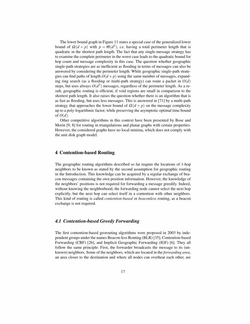
The first contention-based georouting algorithms were proposed in 2003 by inde-pendent groups under the names Beacon-less Routing (BLR) [35], Contention-basedForwarding (CBF) [26], and Implicit Geographic Forwarding (IGF) [6]. They allfollow the same principle: First, the forwarder broadcasts the message to its (un-known) neighbors. Some of the neighbors, which are located in the forwarding area,an area closer to the destination and where all nodes can overhear each other, are
17
the candidates for the next hop and contend for the message (see Figure 13). Theyset a set a timer in accordance to their distance to the destination. More specifically,the timer is determined by a delay function depending on the advance, such that thecandidate closest to the destination has the shortest timeout. Such a delay functionis defined as follows, where a is the advance of the candidate, r the transmissionrange, and tmax the maximum timeout, which defines the length of the contentionperiod.
t(a) = ar · tmax
Once the first timer expires, the respective candidate re-transmits the message. Theother candidates overhear the re-transmission and cancel their scheduled transmis-sions. The re-transmission also serves as a passive acknowledgement to the for-warder.
f t
r
c3c1
c2
c4
Figure 13: Contention-based routing. Only the candidates in the forward-ing area (shaded) participate in the contention. Candidate c1 has the shortesttimeout and takes over the message.
The choice of the forwarding area is implementation-dependent, and there area few possibilities (see [35, 87] such as a 60-sector directed towards the target, acircular region, or the Reuleaux triangle, which is shown in Figure 13. The onlyprerequisite is that all nodes within this area have to be able to overhear each other.Otherwise, two candidates could re-transmit the packet without knowing each other,which leads to an undesired packet duplication. Another problem pointed out in[87] occurs, if two candidates c1 and c2 start their re-transmission almost simulta-neously. Then, these two nodes initiate two contention-rounds in parallel. The newcandidates in the intersection of the transmission range of c1 and c2 receive the firsttransmission by c1 and also overhear the second transmission by c2, which leadsto the misinterpretation that c2 won the contention and became the next hop. If inthis situation there is no other candidate that could hear only one transmission, theforwarding stops and the packet is dropped. This can be solved by storing a hop
18
counter in each packet, so that a candidate cancels its scheduled transmission onlyif another node re-transmitted the packet before and the hop counters are different.
This timer-based or contention-based selection of the candidate enables a com-pletely reactive greedy forwarding without any message overhead. However, thecontention costs a certain delay and the candidates are selected from a rather re-stricted area. It is possible to use the complete greedy area, i.e. all neighbors closerto the destination than the forwarder participate in the contention process. This hasa positive effect on the performance [12], but it requires that the forwarder activelyselects the candidate, which needs additional control messages. This scheme worksas follows: The forwarder broadcasts a request to send (RTS) to its neighbors. Theneighbors being closer to the destination set a timer in accordance to their distanceto the destination. The first candidate whose timer expires replies with a clear tosend (CTS). Then the forwarder sends the data packet immediately. The other can-didates overhear the CTS by the candidate or the data transmission by the forwarderand cancel their schedules replies. Finally, the forwarder sends the packet to theselected candidate by unicast.
The previously described scheme implicitly assumes a continuous time model.Practically, one cannot require a fine-grained time resolution such that no nodes an-swer simultaneously and cause a packet collision. Geographic Random Forwarding(GeRaF) [89] is an approach that solves the problem of colliding control packets.GeRaF uses the RTS/CTS scheme and a forwarding area that includes all neigh-bors closer to the destination than the forwarder. The forwarding area is divided intozones and the candidates within these zones contend for being the forwarder in thenext round. If two candidates from the same zone cause a collision while sendingtheir CTS, they will retransmit it with probability 1/2 in the next round. This prob-abilistic drop out reduces the probability of collisions step by step because collidingnodes from the last round survive with probability 1/2.
In networks where the nodes can adjust their their transmission power, energy canbe saved by adapting the transmission range to a suitable relay node. In beaconlessprotocols, however, the problem is that the relay nodes are not known in advanceand suitable candidates have to be found by broadcasting requests at increasingtransmission ranges. As this probing itself consumes energy, the question is howthe transmission range should be increased. Moreover, if a candidate is found, is itworth to increase the transmission range in order to search for a better candidate?Galluccio et al. [28] address this problem and propose a beaconless routing protocolthat discovers candidates by such probing strategy. In the first round of the proposedalgorithm, candidates are discovered by sending an RTS at an initial transmissionrange, and the best neighbor replies. Then the transmission range is increased, butre-transmitting an RTS at a higher transmission power is connected with some cost.The optimal point for stopping a further range increase is found when the benefit offinding a better neighbor is smaller than the cost of the range increase. The benefithere is a progress factor which is essentially the same as the ratio of the transmissioncost over the progress achieved. The concept of cost-over-progress will be explainedin Section 5.1 in the context of realistic transmission models.
19
4.2 Reactive Recovery Strategies
Contention-based greedy forwarding suffers from the same local minimum prob-lem as described for conventional greedy algorithms. In a contention-based or bea-conless routing algorithm, the recovery cannot rely on known neighborhood infor-mation. A straightforward solution to reactive recovery is the request-response ap-proach of BLR [36]. Whenever the forwarder finds no candidate, it request all neigh-bors to send their position. With this 1-hop knowledge, a local planar subgraph con-struction and face routing as described in Section 3 is applied. This strategy can beseen as reactive beaconing as it involves the complete neighborhood in exchangingposition information.
A reactive scheme for face routing, which guarantees delivery and does not re-quire communication with all neighboring nodes, is described in [42]. The mainproblem is that face routing requires an underlying planar subgraph and planariza-tion requires some knowledge of the neighborhood. According to the two tasks ofplanarization and selecting the next hop edge, two strategies have been proposed:Beaconless Forwarder Planarization (BFP) performs the reactive planarization first,such that face routing can continue; Angular Relaying selects the next edge on aface traversal first and checks then, whether the selected node is part of a planarsubgraph.
BFP is a generalization of the earlier proposed GDBF protocol [11] and canbe used with the Gabriel graph and the relative neighborhood criterion. BFP is pro-posed together with a modified subgraph construction which is similar to the Gabrielgraph but allows to bound the number of messages, which is not possible when us-ing the Gabriel graph criterion. In contrast, the request-response approach of BLRcannot provide this bound on the number of messages as it involves communicationwith all neighbors. BFP uses a delay function of the distance to the forwarder, i.e.the neighbor closest to the forwarder may reply first:
t(d) =dr· tmax
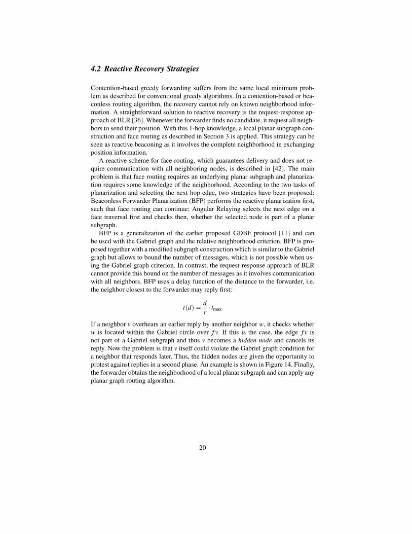
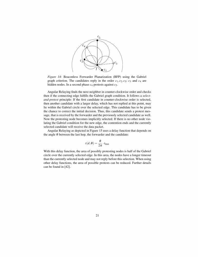
If a neighbor v overhears an earlier reply by another neighbor w, it checks whetherw is located within the Gabriel circle over f v. If this is the case, the edge f v isnot part of a Gabriel subgraph and thus v becomes a hidden node and cancels itsreply. Now the problem is that v itself could violate the Gabriel graph condition fora neighbor that responds later. Thus, the hidden nodes are given the opportunity toprotest against replies in a second phase. An example is shown in Figure 14. Finally,the forwarder obtains the neighborhood of a local planar subgraph and can apply anyplanar graph routing algorithm.
20
f
c
c1
4
c3c2
c5
Figure 14: Beaconless Forwarder Planarization (BFP) using the Gabrielgraph criterion. The candidates reply in the order c1,c2,c5; c3 and c4 arehidden nodes. In a second phase c4 protests against c5.
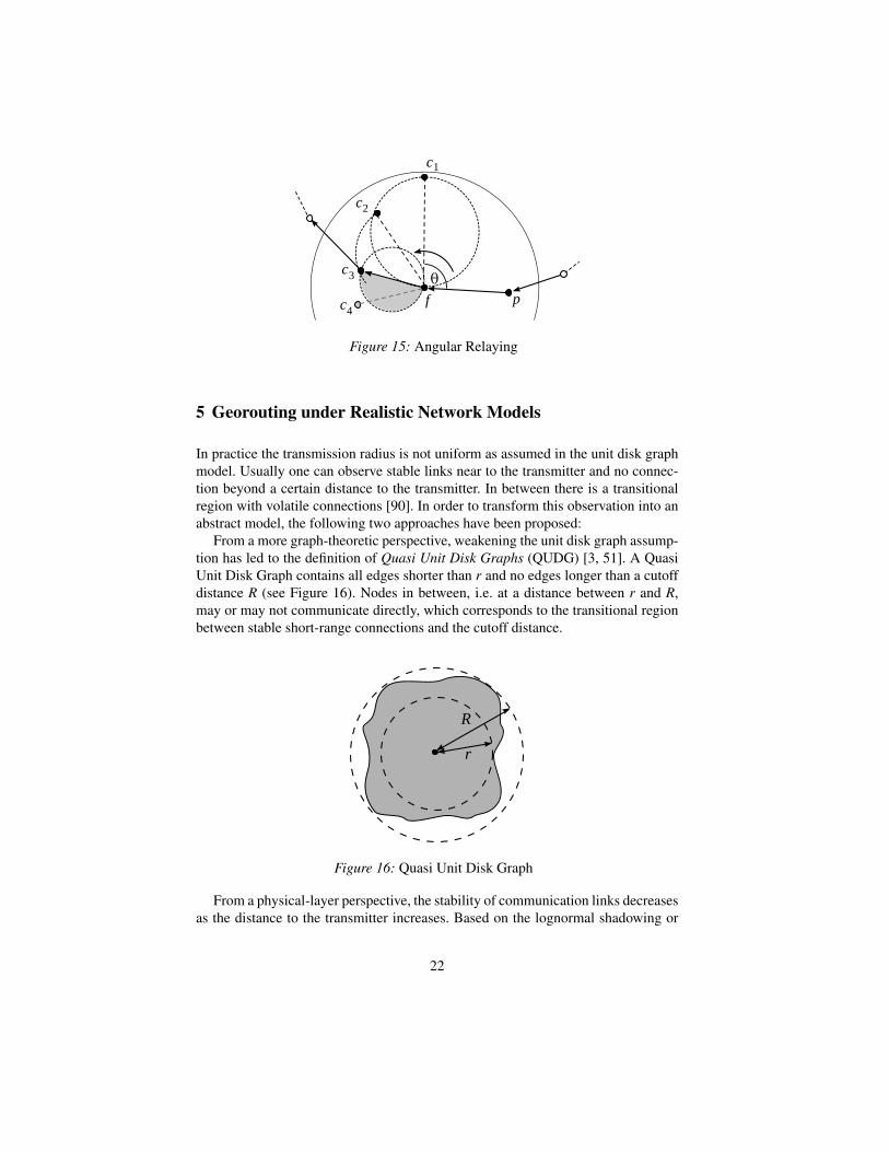
Angular Relaying finds the next neighbor in counter-clockwise order and checksthen if the connecting edge fulfills the Gabriel graph condition. It follows a select-and-protest principle: If the first candidate in counter-clockwise order is selected,then another candidate with a larger delay, which has not replied at this point, maylie within the Gabriel circle over the selected edge. This candidate has to be giventhe chance to correct the initial decision. Thus, this candidate sends a protest mes-sage, that is received by the forwarder and the previously selected candidate as well.Now the protesting node becomes implicitly selected. If there is no other node vio-lating the Gabriel condition for the new edge, the contention ends and the currentlyselected candidate will receive the data packet.
Angular Relaying as depicted in Figure 15 uses a delay function that depends onthe angle θ between the last hop, the forwarder and the candidate:
t(d,θ) =θ
2π· tmax
With this delay function, the area of possibly protesting nodes is half of the Gabrielcircle over the currently selected edge. In this area, the nodes have a longer timeoutthan the currently selected node and may not reply before this selection. When usingother delay functions, the area of possible protests can be reduced. Further detailscan be found in [42].
21
f
c
c
c
p
1
2
3
c4
Figure 15: Angular Relaying
5 Georouting under Realistic Network Models
In practice the transmission radius is not uniform as assumed in the unit disk graphmodel. Usually one can observe stable links near to the transmitter and no connec-tion beyond a certain distance to the transmitter. In between there is a transitionalregion with volatile connections [90]. In order to transform this observation into anabstract model, the following two approaches have been proposed:
From a more graph-theoretic perspective, weakening the unit disk graph assump-tion has led to the definition of Quasi Unit Disk Graphs (QUDG) [3, 51]. A QuasiUnit Disk Graph contains all edges shorter than r and no edges longer than a cutoffdistance R (see Figure 16). Nodes in between, i.e. at a distance between r and R,may or may not communicate directly, which corresponds to the transitional regionbetween stable short-range connections and the cutoff distance.
R
r
Figure 16: Quasi Unit Disk Graph
From a physical-layer perspective, the stability of communication links decreasesas the distance to the transmitter increases. Based on the lognormal shadowing or
22
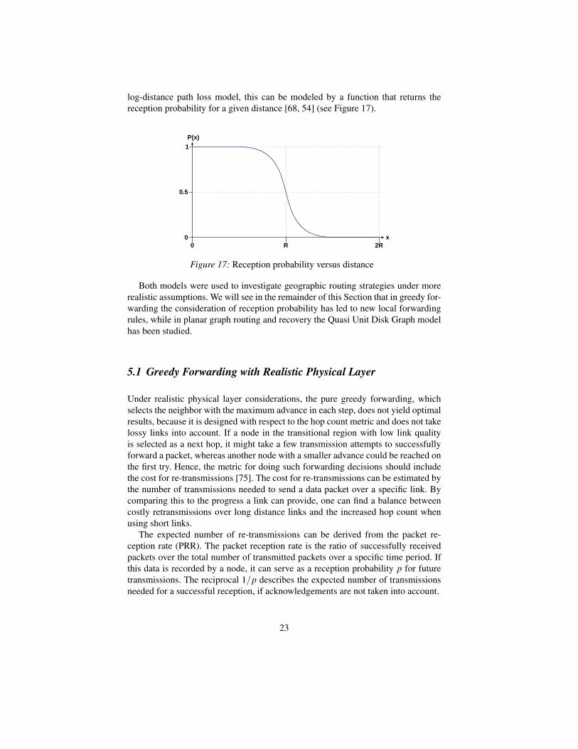
log-distance path loss model, this can be modeled by a function that returns thereception probability for a given distance [68, 54] (see Figure 17).
P(x)
x
1
0.5
00 R 2R
Figure 17: Reception probability versus distance
Both models were used to investigate geographic routing strategies under morerealistic assumptions. We will see in the remainder of this Section that in greedy for-warding the consideration of reception probability has led to new local forwardingrules, while in planar graph routing and recovery the Quasi Unit Disk Graph modelhas been studied.
5.1 Greedy Forwarding with Realistic Physical Layer
Under realistic physical layer considerations, the pure greedy forwarding, whichselects the neighbor with the maximum advance in each step, does not yield optimalresults, because it is designed with respect to the hop count metric and does not takelossy links into account. If a node in the transitional region with low link qualityis selected as a next hop, it might take a few transmission attempts to successfullyforward a packet, whereas another node with a smaller advance could be reached onthe first try. Hence, the metric for doing such forwarding decisions should includethe cost for re-transmissions [75]. The cost for re-transmissions can be estimated bythe number of transmissions needed to send a data packet over a specific link. Bycomparing this to the progress a link can provide, one can find a balance betweencostly retransmissions over long distance links and the increased hop count whenusing short links.
The expected number of re-transmissions can be derived from the packet re-ception rate (PRR). The packet reception rate is the ratio of successfully receivedpackets over the total number of transmitted packets over a specific time period. Ifthis data is recorded by a node, it can serve as a reception probability p for futuretransmissions. The reciprocal 1/p describes the expected number of transmissionsneeded for a successful reception, if acknowledgements are not taken into account.
23
Seada et al. [73] propose to use the product of the packet reception rate andthe advance towards the destination as a metric for forwarding decisions. As a lowPRR causes a high number of re-transmission attempts, this metric penalizes lossylinks. Assumed that the packet reception rate for communicating with the neighborsis known, the forwarder chooses a neighbor based on this metric. In addition theauthors propose different blacklisting strategies to filter out the farthest neighborsor the neighbors with the worst reception rate.
A general metric for dealing with a realistic physical layer model is the cost-over-progress ratio presented by Kuruvila et al. [54, 55]. Minimizing the cost-over-progress ratio means to find a next hop neighbor that requires the minimal costfor transmission per progress towards the destination. The PRR × distance metricin [73] also follows this concept, as it is essentially a ratio of the advance overthe expected number of transmissions, and maximizing this ratio is equivalent tominimizing the cost over progress. Note, that cost can be an arbitrary measure andinclude the number of re-transmission attempts or energy-related metrics. Likewise,progress can be defined in terms of distance, by which the packet advances, or bythe projected distance as in the MFR rule for greedy routing.
Kuruvila et al. use the cost-over-progress concept in their expected progress rout-ing (EPR) [54] algorithm. Progress is here defined as the advance towards the des-tination. As a cost metric they use an expected hop count (EHC), which is based onthe reception probability p and defined as the expected number of transmissions in-cluding data and acknowledgements. It is calculated by 1/p2 +1/p, which includesthe retransmissions due to lost acknowledgements. EPR selects the neighbor thatminimizes EHC over advance.
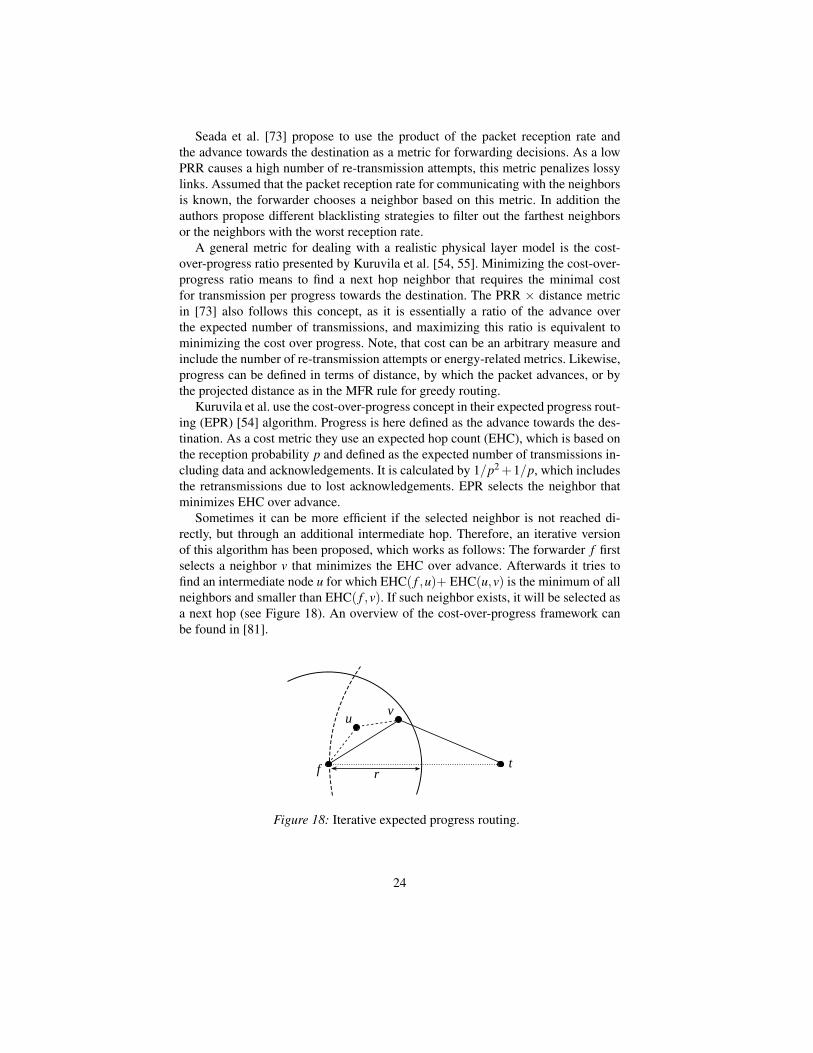
Sometimes it can be more efficient if the selected neighbor is not reached di-rectly, but through an additional intermediate hop. Therefore, an iterative versionof this algorithm has been proposed, which works as follows: The forwarder f firstselects a neighbor v that minimizes the EHC over advance. Afterwards it tries tofind an intermediate node u for which EHC( f ,u)+ EHC(u,v) is the minimum of allneighbors and smaller than EHC( f ,v). If such neighbor exists, it will be selected asa next hop (see Figure 18). An overview of the cost-over-progress framework canbe found in [81].
f t
v
r
u
Figure 18: Iterative expected progress routing.
24
5.2 Localization errors and mobility
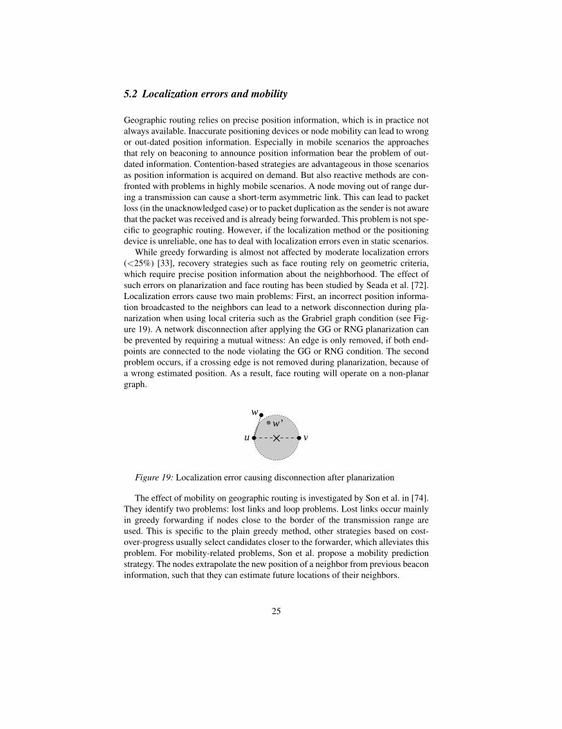
Geographic routing relies on precise position information, which is in practice notalways available. Inaccurate positioning devices or node mobility can lead to wrongor out-dated position information. Especially in mobile scenarios the approachesthat rely on beaconing to announce position information bear the problem of out-dated information. Contention-based strategies are advantageous in those scenariosas position information is acquired on demand. But also reactive methods are con-fronted with problems in highly mobile scenarios. A node moving out of range dur-ing a transmission can cause a short-term asymmetric link. This can lead to packetloss (in the unacknowledged case) or to packet duplication as the sender is not awarethat the packet was received and is already being forwarded. This problem is not spe-cific to geographic routing. However, if the localization method or the positioningdevice is unreliable, one has to deal with localization errors even in static scenarios.
While greedy forwarding is almost not affected by moderate localization errors(<25%) [33], recovery strategies such as face routing rely on geometric criteria,which require precise position information about the neighborhood. The effect ofsuch errors on planarization and face routing has been studied by Seada et al. [72].Localization errors cause two main problems: First, an incorrect position informa-tion broadcasted to the neighbors can lead to a network disconnection during pla-narization when using local criteria such as the Grabriel graph condition (see Fig-ure 19). A network disconnection after applying the GG or RNG planarization canbe prevented by requiring a mutual witness: An edge is only removed, if both end-points are connected to the node violating the GG or RNG condition. The secondproblem occurs, if a crossing edge is not removed during planarization, because ofa wrong estimated position. As a result, face routing will operate on a non-planargraph.
u v
ww’
Figure 19: Localization error causing disconnection after planarization
The effect of mobility on geographic routing is investigated by Son et al. in [74].They identify two problems: lost links and loop problems. Lost links occur mainlyin greedy forwarding if nodes close to the border of the transmission range areused. This is specific to the plain greedy method, other strategies based on cost-over-progress usually select candidates closer to the forwarder, which alleviates thisproblem. For mobility-related problems, Son et al. propose a mobility predictionstrategy. The nodes extrapolate the new position of a neighbor from previous beaconinformation, such that they can estimate future locations of their neighbors.
25
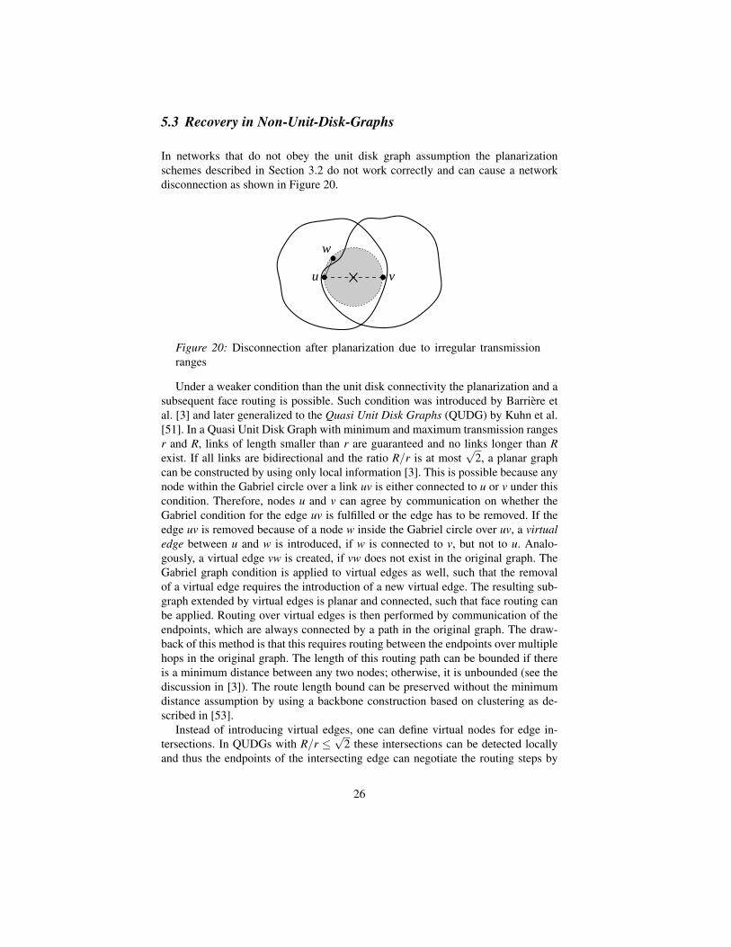
5.3 Recovery in Non-Unit-Disk-Graphs
In networks that do not obey the unit disk graph assumption the planarizationschemes described in Section 3.2 do not work correctly and can cause a networkdisconnection as shown in Figure 20.
u v
w
Figure 20: Disconnection after planarization due to irregular transmissionranges
Under a weaker condition than the unit disk connectivity the planarization and asubsequent face routing is possible. Such condition was introduced by Barriere etal. [3] and later generalized to the Quasi Unit Disk Graphs (QUDG) by Kuhn et al.[51]. In a Quasi Unit Disk Graph with minimum and maximum transmission rangesr and R, links of length smaller than r are guaranteed and no links longer than Rexist. If all links are bidirectional and the ratio R/r is at most
√2, a planar graph
can be constructed by using only local information [3]. This is possible because anynode within the Gabriel circle over a link uv is either connected to u or v under thiscondition. Therefore, nodes u and v can agree by communication on whether theGabriel condition for the edge uv is fulfilled or the edge has to be removed. If theedge uv is removed because of a node w inside the Gabriel circle over uv, a virtualedge between u and w is introduced, if w is connected to v, but not to u. Analo-gously, a virtual edge vw is created, if vw does not exist in the original graph. TheGabriel graph condition is applied to virtual edges as well, such that the removalof a virtual edge requires the introduction of a new virtual edge. The resulting sub-graph extended by virtual edges is planar and connected, such that face routing canbe applied. Routing over virtual edges is then performed by communication of theendpoints, which are always connected by a path in the original graph. The draw-back of this method is that this requires routing between the endpoints over multiplehops in the original graph. The length of this routing path can be bounded if thereis a minimum distance between any two nodes; otherwise, it is unbounded (see thediscussion in [3]). The route length bound can be preserved without the minimumdistance assumption by using a backbone construction based on clustering as de-scribed in [53].
Instead of introducing virtual edges, one can define virtual nodes for edge in-tersections. In QUDGs with R/r ≤
√2 these intersections can be detected locally
and thus the endpoints of the intersecting edge can negotiate the routing steps by
26
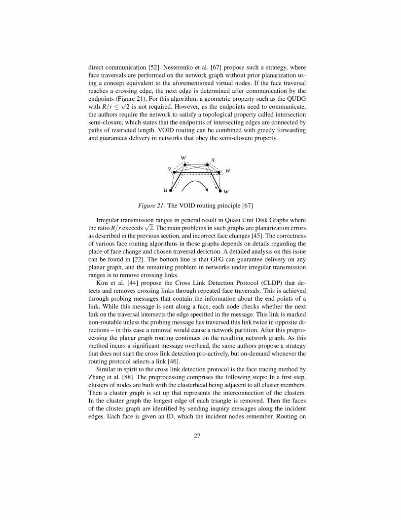
direct communication [52]. Nesterenko et al. [67] propose such a strategy, whereface traversals are performed on the network graph without prior planarization us-ing a concept equivalent to the aforementioned virtual nodes. If the face traversalreaches a crossing edge, the next edge is determined after communication by theendpoints (Figure 21). For this algorithm, a geometric property such as the QUDGwith R/r ≤
√2 is not required. However, as the endpoints need to communicate,
the authors require the network to satisfy a topological property called intersectionsemi-closure, which states that the endpoints of intersecting edges are connected bypaths of restricted length. VOID routing can be combined with greedy forwardingand guarantees delivery in networks that obey the semi-closure property.
u
v
w x
w
w
Figure 21: The VOID routing principle [67]
Irregular transmission ranges in general result in Quasi Unit Disk Graphs wherethe ratio R/r exceeds
√2. The main problems in such graphs are planarization errors
as described in the previous section, and incorrect face changes [45]. The correctnessof various face routing algorithms in those graphs depends on details regarding theplace of face change and chosen traversal deriction. A detailed analysis on this issuecan be found in [22]. The bottom line is that GFG can guarantee delivery on anyplanar graph, and the remaining problem in networks under irregular transmissionranges is to remove crossing links.
Kim et al. [44] propose the Cross Link Detection Protocol (CLDP) that de-tects and removes crossing links through repeated face traversals. This is achievedthrough probing messages that contain the information about the end points of alink. While this message is sent along a face, each node checks whether the nextlink on the traversal intersects the edge specified in the message. This link is markednon-routable unless the probing message has traversed this link twice in opposite di-rections – in this case a removal would cause a network partition. After this prepro-cessing the planar graph routing continues on the resulting network graph. As thismethod incurs a significant message overhead, the same authors propose a strategythat does not start the cross link detection pro-actively, but on-demand whenever therouting protocol selects a link [46].
Similar in spirit to the cross link detection protocol is the face tracing method byZhang et al. [88]. The preprocessing comprises the following steps: In a first step,clusters of nodes are built with the clusterhead being adjacent to all cluster members.Then a cluster graph is set up that represents the interconnection of the clusters.In the cluster graph the longest edge of each triangle is removed. Then the facesof the cluster graph are identified by sending inquiry messages along the incidentedges. Each face is given an ID, which the incident nodes remember. Routing on
27
this graph is done by traversing the faces of the cluster graph (face tracing). TheIDs of traversed faces are stored in the message, and the order of the traversed facesis selected by a depth-first search. This guarantees that all parts of the network canbe reached.
A further strategy for routing in non-unit disk graphs is GDSTR [56], a protocolthat is based on a distributed spanning tree construction. This spanning tree containsin each node the information about the area that is covered by the subtree. More pre-cisely, a node stores the convex hull of all node locations in the subtree and also theconvex hull information of its descendants. For a recovery from a local minimum,a message is routed upwards in the tree until a node is found, whose convex hullcontains the destination. From this point, the message is routed downwards in thetree until the destination is found.
Recovery strategies for arbitrary non-unit disk graphs such as CLDP and GDSTRneed multi-hop communication to identify crossing links or to gather the necessaryinformation for successful recovery, i.e. these protocols are not localized. On theother hand, localized protocols such as GFG, GPSR and GOAFR cannot guaranteedelivery in arbitrary non-unit disk graphs.
6 Geocasting and Multipath Strategies
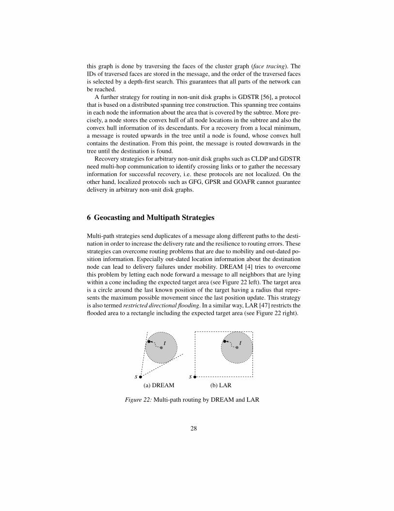
Multi-path strategies send duplicates of a message along different paths to the desti-nation in order to increase the delivery rate and the resilience to routing errors. Thesestrategies can overcome routing problems that are due to mobility and out-dated po-sition information. Especially out-dated location information about the destinationnode can lead to delivery failures under mobility. DREAM [4] tries to overcomethis problem by letting each node forward a message to all neighbors that are lyingwithin a cone including the expected target area (see Figure 22 left). The target areais a circle around the last known position of the target having a radius that repre-sents the maximum possible movement since the last position update. This strategyis also termed restricted directional flooding. In a similar way, LAR [47] restricts theflooded area to a rectangle including the expected target area (see Figure 22 right).
Figure 22: Multi-path routing by DREAM and LAR
28

Apart from the flooding algorithms of DREAM and LAR, multi-path algorithmscan be based directly on greedy forwarding or planar graph routing. Greedy forward-ing can be generalized by selecting the c best neighbors according to the forwardingcriterion in each step, instead of considering only one candidate [61]. A multi-pathstrategy based on face traversals is the concurrent face routing (CFR) [13] algo-rithm. CFR follows the idea of face routing and duplicates a message whenever aface is encountered that is closer to the destination. Then the duplicate traverses thenew face, while the original continues the traversal of the old face.
While multi-path strategies try to increase the chance of reaching a single target,geocasting algorithms deliver a message to multiple targets within a specific geo-graphic area. Flooding-based strategies such as LAR allow to perform geocasting.However, sending a message by unicast into the target area and subsequent floodingwith geographic restrictions is not sufficient to guarantee delivery to all target nodes.If the target area is intersected by a void region, i.e. there are two nodes within thetarget area that are only connected by a path that leaves the target area, then therestricted flooding reaches the first node, but stops at the border of the target areaand does not reach the second node. In this case, additional messages have to besent around the target area to reach the second node. Here, face routing can serveas strategy to traverse the void region and find further nodes within the target area.[79].
A comprehensive overview on geocasting techniqes can be found in the surveysby Jiang and Camp [40], Maihofer [65] and Stojmenovic [80].
7 Location Service
The third assumption for position-based routing is that the position of the destinationnode is known. Providing each requesting node with this information is the task ofa location services.
There are similarities between the problem of locating the destination node andthe route discovery problem in ad hoc routing protocols. Proactive schemes dis-seminate routing information before it is needed, whereas reactive schemes start theroute discovery on demand. Similarly, in the case of a location service the questioncan be asked, whether location information should be spread proactively or whethera requesting node should look up this information on demand.
Location services can be roughly divided into the following categories:
• Flooding-based location dissemination• Quorum-based and home-zone-based strategies• Movement-based location dissemination
Flooding-based location dissemination is fastest way to spread information in thenetwork. It is used in DREAM [4] and LAR [47]. In DREAM each node main-tains a location database and distributes its own position proactively throughout thenetwork at regular intervals. In contrast, LAR works reactively: If the destination’s
29
position is unknown, the network is flooded with a route request, while the floodedarea is restricted to a geographic region where the destination is expected. Flooding-based approaches distribute location information effectively, but at the expense of ahigh communication overhead.
Quorum-based and home-zone-based strategies try to reduce the high commu-nication overhead of flooding. In quorum-based approaches, the location informa-tion is held by a group of nodes, which have to be contacted to obtain the targetlocation, whereas in home-zone-based approaches the location is stored by a sin-gle node, which is determined by a geographic location. Early approaches for thiskind of strategies were proposed by Stojmenovic in [76, 77]. A good example fora quorum-based location service, which uses a geographic criterion for selectingthe quorum, is described in [62]. In this scheme the position information is storedalong “rows and columns”, i.e. a row of nodes having almost the same latitude anda column of nodes with similar longitude store the location information for a spe-cific node. In order to distribute the information, messages are sent along longitudesand latitudes in the network, using geographic routing. A location query can be sentsimply in longitudinal or in latitudinal direction in order to find a node of the quo-rum. For a location service, the nodes of a quorum do not have to be geographicallyco-located. In the Grid Location Service (GLS) by Li et al. [58] the location serversare distributed according to a hierarchical subdivision of the plane, which is used toassign location information to specific nodes.
In home-zone-based approaches each node has a home-zone with another nodethat can answer location queries. This is similar to the concept of the home agent inMobile IP. In order to determine a home zone in a distributed way, a hash functioncan be used that maps addresses to geographic locations. This is the idea of Geo-graphic Hash Tables (GHT) by Ratnasamy et al. [69]. Given a node and its locationas a key-value pair, a hash function maps the key to a geographic location. The nodeclosest to this location then stores the key-value pair. Location queries are routed tothe hash location using geographic routing. As the hash location usually does notmatch exactly a node’s location, a face traversal along the nodes surrounding thehash location finally returns the closest node that answers the query.
A movement-based dissemination strategy is presented in [30]. Here, the nodesdo not spread information over multiple hops. Location information is exchangedonly locally, but by the nodes’ movement the information is disseminated in the net-work. Node exchange location information whenever they encounter other nodes.Thus, the information dissemination is provided by mobility. Each node holds a ta-ble of locations and timestamps of the last encounter with other nodes. Required thatthe mobility pattern allows an encounter of all nodes, this information is sufficientto route messages by following the newest information about the target node.
An overview of location services can be found in [78] and [23].
30
8 Applications
Due to its stateless nature, geographic routing is considered to be superior to topo-logical routing in dynamic and mobile networks. However, without topological in-formation, the routing success depends on the likelihood of encountering local min-ima and the robustness of the recovery strategy. Many known recovery strategiesare limited under practical considerations because they rely on unrealistic assump-tions or work inefficiently because of a high communication overhead by traversalsor local flooding. Greedy forwarding, especially the contention-based variants, canprovide efficient and reactive routing, also in mobile networks. Consequently, thesestrategies are attractive for vehicular networks and have been used in projects oncar-to-car communication. Vehicular networks aim at providing a fast and secureexchange of safety information such as obstacle warnings or lane change warningsor the communication with road side units for the purpose of traffic informationand infotainment applications. As cars can easily be equipped with positioning ca-pabilities and wireless transceivers, they provide a suitable platform for geographicrouting protocols.
A real-world implementation of a geographic routing protocol was used for inter-vehicle communication in the FleetNet project [31]: Cars were equipped with GPS,a WLAN transceiver and a Linux router. GPSR was used as a routing protocol andtarget locations were obtained reactively by flooding a request. Experimental resultswith a small number of cars in a static and mobile setting are described in [32] and[66]. At the same time, the idea of contention-based forwarding [25] was developedwithin the same project and adopted for vehicular networks [24]. As contention-based forwarding is a pure greedy strategy, which is prone to the local minimumproblem, a specific recovery strategy for street scenarios was developed [64]: TheGreedy Perimeter Coordinator Routing (GPCR) is based on the idea that the streets,where network nodes reside, form a natural planar graph. Nodes on junctions canserve as coordinators and decide to which junction a packet will be forwarded, whilebetween the junctions a plain greedy scheme can be used. Based on the assumptionthat street and junctions form a planar graph, a recovery strategy using the right-hand rule can be applied. Whether nodes are on junctions and obtain the role of acoordinator can be determined by using beaconing with 2-hop information or froma evaluating the linear relationship between the neighbors positions statistically.
The work on communication in vehicular networks is continued in the Network-on-Wheels (NOW) project [18], which targets at developing reliable and secure pro-tocols for car-to-car and car-to-infrastructure communication. Within this project,various protocols were developed such as a greedy forwarding with transmit powercontrol [17] to reduce interference, or a protocol to reduce the beaconing load bypower control [85].
31
9 Conclusion
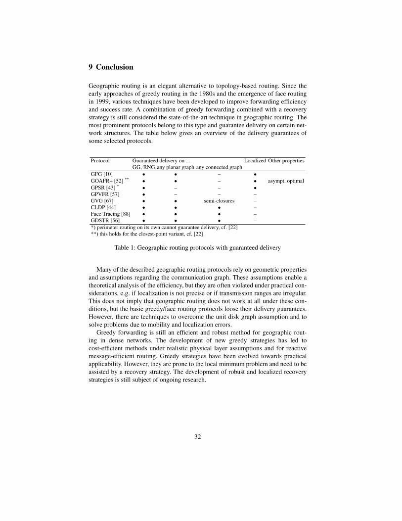
Geographic routing is an elegant alternative to topology-based routing. Since theearly approaches of greedy routing in the 1980s and the emergence of face routingin 1999, various techniques have been developed to improve forwarding efficiencyand success rate. A combination of greedy forwarding combined with a recoverystrategy is still considered the state-of-the-art technique in geographic routing. Themost prominent protocols belong to this type and guarantee delivery on certain net-work structures. The table below gives an overview of the delivery guarantees ofsome selected protocols.
Protocol Guaranteed delivery on ... Localized Other propertiesGG, RNG any planar graph any connected graph
GFG [10] • • – •GOAFR+ [52] ** • • – • asympt. optimalGPSR [43] * • – – •GPVFR [57] • – – –GVG [67] • • semi-closures –CLDP [44] • • • –Face Tracing [88] • • • –GDSTR [56] • • • –*) perimeter routing on its own cannot guarantee delivery, cf. [22]**) this holds for the closest-point variant, cf. [22]
Table 1: Geographic routing protocols with guaranteed delivery
Many of the described geographic routing protocols rely on geometric propertiesand assumptions regarding the communication graph. These assumptions enable atheoretical analysis of the efficiency, but they are often violated under practical con-siderations, e.g. if localization is not precise or if transmission ranges are irregular.This does not imply that geographic routing does not work at all under these con-ditions, but the basic greedy/face routing protocols loose their delivery guarantees.However, there are techniques to overcome the unit disk graph assumption and tosolve problems due to mobility and localization errors.
Greedy forwarding is still an efficient and robust method for geographic rout-ing in dense networks. The development of new greedy strategies has led tocost-efficient methods under realistic physical layer assumptions and for reactivemessage-efficient routing. Greedy strategies have been evolved towards practicalapplicability. However, they are prone to the local minimum problem and need to beassisted by a recovery strategy. The development of robust and localized recoverystrategies is still subject of ongoing research.
32

Acknowledgements
The author would like to thank Hannes Frey for many helpful suggestions and dis-cussions.
References
1. K. Alzoubi, X.-Y. Li, Y. Wang, P.-J. Wan, and O. Frieder, “Geometric spanners for wirelessad hoc networks,” IEEE Trans. on Parallel and Distributed Systems, vol. 14 (4), pp. 408–421,2003.
2. N. Arad and Y. Shavitt, “Minimizing recovery state in geographic ad-hoc routing,” in 7th ACMInt. Symposium on Mobile Ad hoc Networking and Computing (MobiHoc), 2006, pp. 13–24.
3. L. Barriere, P. Fraigniaud, L. Narayanan, and J. Opatrny, “Robust position-based routing inwireless ad hoc networks with irregular transmission ranges,” Wireless Communications andMobile Computing, vol. 3 (1), pp. 141–153, Mar. 2003.
4. S. Basagni, I. Chlamtac, V. R. Syrotiuk, and B. A. Woodward, “A distance routing effect algo-rithm for mobility (DREAM),” in 4th Annual Int. Conf. on Mobile Computing and Networking(MobiCom), 1998, pp. 76–84.
5. A. Blum, P. Raghavan, and B. Schieber, “Navigating in unfamiliar geometric terrain,” SIAMJournal on Computing, vol. 26 (1), pp. 110–137, Feb. 1997.
6. B. Blum, T. He, S. Son, and J. Stankovic, “IGF: A state-free robust communication protocolfor wireless sensor networks,” University of Virginia, USA, Tech. Rep. CS-2003-11, Apr.2003.
7. P. Bose, L. Devroye, W. Evans, and D. Kirkpatrick, “On the spanning ratio of gabriel graphsand beta-skeletons,” SIAM Journal on Discrete Mathematics, vol. 20 (2), pp. 412–427, 2006.
8. P. Bose and P. Morin, “Competitive online routing in geometric graphs,” Theoretical ComputerScience, vol. 324 (2-3), pp. 273–288, Sep. 2004.
9. ——, “Online routing in triangulations,” SIAM Journal on Computing, vol. 33 (4), pp. 937–951, May 2004.
10. P. Bose, P. Morin, I. Stojmenovic, and J. Urrutia, “Routing with guaranteed delivery in adhoc wireless networks,” in 3rd Int. Workshop on Discrete Algorithms and Methods for MobileComputing and Communications (DIAL-M ’99), 1999, pp. 48–55.
11. M. Chawla, N. Goel, K. Kalaichelvan, A. Nayak, and I. Stojmenovic, “Beaconless position-based routing with guaranteed delivery for wireless ad hoc and sensor networks,” ACTA AU-TOMATICA SINICA, vol. 32 (6), pp. 846–855, Nov. 2006.
12. D. Chen, J. Deng, and P. K. Varshney, “Selection of a forwarding area for contention-basedgeographic forwarding in wireless multi-hop networks,” IEEE Trans. on Vehicular Technol-ogy, vol. 56 (5), pp. 3111–3122, Sep. 2007.
13. T. Clouser, M. Miyashita, and M. Nesterenko, “Fast geometric routing with concurrent facetraversal,” in 12th Int. Conference on Principles of Distributed Systems (OPODIS’08), 2008,pp. 346–362.
14. S. Datta, I. Stojmenovic, and J. Wu, “Internal node and shortcut based routing with guaranteeddelivery in wireless networks,” in IEEE Int. Conference on Distributed Computing and Sys-tems (Wireless Networks and Mobile Computing Workshop WNMC), Apr. 2001, pp. 461–466.
15. ——, “Internal node and shortcut based routing with guaranteed delivery in wireless net-works,” Cluster Computing, vol. 5 (2), pp. 169–178, 2002.
16. Q. Fang, J. Gao, and L. J. Guibas, “Locating and bypassing routing holes in sensor networks,”in 23rd Conference of the IEEE Communications Society (INFOCOM), Mar. 2004.
17. A. Festag, R. Baldessari, and H. Wang, “On power-aware greedy forwarding in highway sce-narios,” in 4th Int. Workshop on Intelligent Transportation (WIT), 2007.
33
18. A. Festag, G. Noecker, M. Strassberger, A. Lubke, B. Bochow, M. Torrent-Moreno,S. Schnaufer, R. Eigner, C. Catrinescu, and J. Kunisch, “NoW - network on wheels: Projectobjectives, technology and achievements,” in 6th Int. Workshop on Intelligent Transportation(WIT), Mar. 2008.
19. G. G. Finn, “Routing and addressing problems in large metropolitan-scale internetworks,”University of Southern California, Tech. Rep. ISI/RR-87-180, Mar. 1987.
20. H. Frey, “Geographical cluster based routing with guaranteed delivery,” in 2nd IEEE Int. Con-ference on Mobile Ad-hoc and Sensor Systems (MASS 2005), 2005.
21. H. Frey and S. Ruhrup, “Paving the way towards reactive planar spanner construction in wire-less networks,” in GI/ITG Fachtagung Kommunikation in Verteilten Systemen (KiVS 2009),Mar. 2009.
22. H. Frey and I. Stojmenovic, “On delivery guarantees of face and combined greedy-face routingin ad hoc and sensor networks,” in 12th Annual Int. Conference on Mobile Computing andNetworking (MobiCom), 2006, pp. 390–401.
23. R. Friedman and G. Kliot, “Location services in wireless ad hoc and hybrid networks: Asurvey,” Israel Institute of Technology, Haifa, Israel, Tech. Rep. CS-2006-10, 2006.
24. H. Fußler, H. Hartenstein, J. Widmer, M. Mauve, and W. Effelsberg, “Contention-based for-warding for street scenarios,” in 1st Int. Workshop in Intelligent Transportation (WIT 2004),Mar. 2004, pp. 155–160.
25. H. Fußler, J. Widmer, M. Kasemann, M. Mauve, and H. Hartenstein, “Beaconless Position-Based Routing for Mobile Ad-Hoc Networks,” Department of Computer Science, Universityof Mannheim, Germany, Tech. Rep. TR-03-001, Feb. 2003.
26. H. Fußler, J. Widmer, M. Mauve, and H. Hartenstein, “A novel forwarding paradigm forposition-based routing (with implicit addressing),” in IEEE 18th Annual Workshop on Com-puter Communications (CCW 2003), Oct. 2003, pp. 194–200.
27. K. R. Gabriel and R. R. Sokal, “A new statistical approach to geographic variation analysis,”Systematic Zoology, vol. 18 (3), pp. 259–278, 1969.
28. L. Galluccio, A. Leonardi, G. Morabito, and S. Palazzo, “A mac/routing cross-layer approachto geographic forwarding in wireless sensor networks,” Ad Hoc Networks, vol. 5 (6), pp. 872–884, Aug. 2007.
29. J. Gao, L. J. Guibas, J. E. Hershberger, L. Zhang, and A. Zhu, “Geometric spanner for routingin mobile networks,” in 2nd ACM Int. Symposium on Mobile Ad Hoc Networking & Computing(MobiHoc), 2001, pp. 45–55.
30. M. Grossglauser and M. Vetterli, “Locating mobile nodes with ease: learning efficient routesfrom encounter histories alone,” IEEE/ACM Trans. on Networking, vol. 14 (3), pp. 457–469,2006.
31. H. Hartenstein, B. Bochow, A. Ebner, M. Lott, M. Radimirsch, and D. Vollmer, “Position-aware ad hoc wireless networks for inter-vehicle communications: the fleetnet project,” in2nd ACM Int. Symposium on Mobile Ad Hoc Networking & Computing (MobiHoc), 2001, pp.259–262.
32. H. Hartenstein, H. Fußler, M. Mauve, and W. J. Franz, “Simulation results and a proof-of-concept implementation of the fleetnet position-based router,” in 8th International Conferenceon Personal Wireless Communications (PWC), 2003, pp. 192–197.
33. T. He, C. Huang, B. M. Blum, J. A. Stankovic, and T. F. Abdelzaher, “Range-free localizationand its impact on large scale sensor networks,” Trans. on Embedded Computing Sys., vol. 4(4), pp. 877–906, 2005.
34. T. He, J. A. Stankovic, C. Lu, and T. Abdelzaher, “Speed: A stateless protocol for real-timecommunication in sensor networks,” in International Conference on Distributed ComputingSystems (ICDCS), 2003, p. 46.
35. M. Heissenbuttel and T. Braun, “A novel position-based and beacon-less routing algorithmfor mobile ad-hoc networks,” in 3rd IEEE Workshop on Applications and Services in WirelessNetworks, 2003, pp. 197–209.
36. M. Heissenbuttel, T. Braun, T. Bernoulli, and M. Walchli, “BLR: Beacon-less routing algo-rithm for mobile ad-hoc networks,” Computer Communications, vol. 27 (11), pp. 1076–1086,Jul. 2004.
34
37. J. Hightower and G. Borriello, “Location systems for ubiquitous computing,” IEEE Computer,vol. 34 (8), pp. 57–66, Aug. 2001.
38. T.-C. Hou and V. Li, “Transmission range control in multihop packet radio networks,” IEEETrans. on Communications, vol. 34 (1), pp. 38–44, Jan. 1986.
39. J. W. Jaromczyk and G. T. Toussaint, “Relative neighborhood graphs and their relatives,” Proc.of the IEEE, vol. 80 (9), pp. 1502–1517, 1992.
40. X. Jiang and T. Camp, “Review of geocasting protocols for a mobile ad hoc network,” inProceedings of the Grace Hopper Celebration (GHC), 2002.
41. D. B. Johnson and D. A. Maltz, “Dynamic Source Routing in Ad Hoc Wireless Networks,” inMobile Computing, T. Imielinski and H. Korth, Eds. Kluwer Academic Publishers, 1996, pp.152–181.
42. H. Kalosha, A. Nayak, S. Ruhrup, and I. Stojmenovic, “Select-and-protest-based beaconlessgeorouting with guaranteed delivery in wireless sensor networks,” in 27th Annual IEEE Con-ference on Computer Communications (INFOCOM), Apr. 2008, pp. 346–350.
43. B. Karp and H. T. Kung, “GPSR: greedy perimeter stateless routing for wireless networks,”in 6th Annual ACM/IEEE Int. Conference on Mobile Computing and Networking (MobiCom),2000, pp. 243–254.
44. Y.-J. Kim, R. Govindan, B. Karp, and S. Shenker, “Geographic routing made practical,” in2nd USENIX/ACM Symposium on Networked System Design and Implementation (NSDI’05),May 2005, pp. 217–230.
45. ——, “On the pitfalls of geographic routing,” in 3rd Int. Workshop on Discrete Algorithmsand Methods for Mobile Computing and Communications – Principles of Mobile Computing(DIALM-POMC), 2005, pp. 34–43.
46. ——, “Lazy cross-link removal for geographic routing,” in 4th Int. Conference on EmbeddedNetworked Sensor Systems (SenSys’06), 2006, pp. 112–124.
47. Y.-B. Ko and N. H. Vaidya, “Location-aided routing (LAR) in mobile ad hoc networks,” in 4thAnnual ACM/IEEE Int. Conference on Mobile Computing and Networking (MobiCom), Oct.1998, pp. 66–75.
48. E. Kranakis, H. Singh, and J. Urrutia, “Compass routing on geometric networks,” in 11thCanadian Conference on Computational Geometry (CCCG’99), Aug. 1999, pp. 51–54.
49. F. Kuhn, R. Wattenhofer, Y. Zhang, and A. Zollinger, “Geometric ad-hoc routing: Of theoryand practice,” in 22th ACM Symposium on Principles of Distributed Computing (PODC’03),2003, pp. 63–72.
50. F. Kuhn, R. Wattenhofer, and A. Zollinger, “Asymptotically optimal geometric mobile ad-hocrouting,” in 6th Int. Workshop on Discrete Algorithms and Methods for Mobile Computing andCommunications (DIALM). ACM Press, 2002, pp. 24–33.
51. ——, “Ad-hoc networks beyond unit disk graphs,” in 2003 Joint Workshop on Foundations ofMobile Computing (DIALM-POMC), 2003, pp. 69–78.
52. ——, “Worst-case optimal and average-case efficient geometric ad-hoc routing,” in 4th ACMInt. Symposium on Mobile Ad Hoc Networking and Computing (MobiHoc), 2003, pp. 267–278.
53. ——, “Ad hoc networks beyond unit disk graphs,” Wireless Networks, vol. 14 (5), pp. 715–729, 2008.
54. J. Kuruvila, A. Nayak, and I. Stojmenovic, “Hop count optimal position-based packet routingalgorithms for ad hoc wireless networks with a realistic physical layer,” IEEE Journal onSelected Areas in Communications, vol. 23 (6), pp. 1267–1275, 2005.
55. ——, “Greedy localized routing for maximizing probability of delivery in wireless ad hocnetworks with a realistic physical layer,” J. Parallel Distrib. Comput., vol. 66 (4), pp. 499–506, 2006.
56. B. Leong, B. Liskov, and R. Morris, “Geographic routing without planarization,” in 3rdUSENIX/ACM Symposium on Networked Systems Design and Implementation (NSDI ’06),2006, pp. 339–352.
57. B. Leong, S. Mitra, and B. Liskov, “Path vector face routing: Geographic routing with localface information,” in 13th IEEE Int. Conference on Network Protocols (ICNP’05), 2005, pp.147–158.
35
58. J. Li, J. Jannotti, D. S. J. De Couto, D. R. Karger, and R. Morris, “A scalable location servicefor geographic ad hoc routing,” in 6th Annual Int. Conference on Mobile Computing andNetworking (MobiCom), 2000, pp. 120–130.
59. X.-Y. Li, G. Calinescu, and P.-J. Wan, “Distributed construction of planar spanner and routingfor ad hoc wireless networks,” in 21st Annual IEEE Conference on Computer Communications(INFOCOM), 2002, pp. 1268–1277.
60. X.-Y. Li, I. Stojmenovic, and Y. Wang, “Partial delaunay triangulation and degree limitedlocalized bluetooth scatternet formation,” IEEE Trans. on Parallel and Distributed Systems,vol. 15 (4), pp. 350–361, 2004.
61. X. Lin, M. Lakshdisi, and I. Stojmenovic, “Location based localized alternate, disjoint, multi-path and component routing schemes for wireless networks,” in 2nd ACM Int. Symposium onMobile Ad Hoc Networking & Computing (MobiHoc), Oct. 2001, pp. 287–290.
62. D. Liu, X. Jia, and I. Stojmenovic, “Quorum and connected dominating sets based locationservice in wireless ad hoc, sensor and actuator networks,” Computer Communications, vol. 30(18), pp. 3627–3643, 2007.
63. W.-J. Liu and K.-T. Feng, “Greedy anti-void routing protocol for wireless sensor networks,”IEEE Communications Letters, vol. 11 (7), pp. 562–564, Jul. 2007.
64. C. Lochert, M. Mauve, H. Fußler, and H. Hartenstein, “Geographic routing in city scenarios,”SIGMOBILE Mobile Computing and Communication Reviews, vol. 9 (1), pp. 69–72, 2005.
65. C. Maihofer, “A survey of geocast routing protocols,” IEEE Communications Surveys andTutorials, vol. 6 (2), pp. 32–42, 2004.
66. M. Moske, H. Fußler, H. Hartenstein, and W. Franz, “Performance measurements of a vehicu-lar ad hoc network,” in 59th IEEE Vehicular Technology Conference (VTC 2004-Spring), May2004, pp. 2116–2120.
67. M. Nesterenko and A. Vora, “Void traversal for guaranteed delivery in geometric routing,”in IEEE Int. Conference on Mobile Adhoc and Sensor Systems (MASS’05), Nov. 2005, pp. 6pp.–715.
68. L. Qin and T. Kunz, “On-demand routing in manets: The impact of a realistic physical layermodel,” in 2nd Int. Conference on Ad-hoc, Mobile, and Wireless Networks (ADHOC-NOW),2003, pp. 37–48.
69. S. Ratnasamy, B. Karp, L. Yin, F. Yu, D. Estrin, R. Govindan, and S. Shenker, “Ght: A geo-graphic hash table for data-centric storage in sensornets,” in 1st ACM Int. Workshop on Wire-less Sensor Networks and Applications (WSNA’02), Sep. 2002.
70. S. Ruhrup and C. Schindelhauer, “Competitive time and traffic analysis of position-based rout-ing using a cell structure,” in 5th IEEE Int. Workshop on Algorithms for Wireless, Mobile, AdHoc and Sensor Networks (WMAN’05), 2005, p. 248.
71. ——, “Online multi-path routing in a maze,” in 17th Int. Symposium on Algorithms and Com-putation (ISAAC), LNCS 4288. Springer-Verlag, Dec. 2006, pp. 650–659.
72. K. Seada, A. Helmy, and R. Govindan, “Modeling and analyzing the correctness of geographicface routing under realistic conditions,” Ad Hoc Networks, vol. 5 (6), pp. 855–871, 2007.
73. K. Seada, M. Zuniga, A. Helmy, and B. Krishnamachari, “Energy-efficient forwarding strate-gies for geographic routing in lossy wireless sensor networks,” in 2nd Int. Conference onEmbedded Networked Sensor Systems (SenSys’04), 2004, pp. 108–121.
74. D. Son, A. Helmy, and B. Krishnamachari, “The effect of mobility-induced location errors ongeographic routing in mobile ad hoc and sensor networks: Analysis and improvement usingmobility prediction,” IEEE Trans. on Mobile Computing, vol. 3 (3), pp. 233–245, 2004.
75. I. Stojmenovic, A. Nayak, and J. Kuruvila, “Design guidelines for routing protocols in ad hocand sensor networks with a realistic physical layer,” IEEE Communications Magazine, vol. 43(3), pp. 101–106, Mar. 2005.
76. I. Stojmenovic, “Home agent based location update and destination search schemes in ad hocwireless networks,” University of Ottawa, Tech. Rep. TR-99-10, Sep. 1999.
77. ——, “A routing strategy and quorum based location update scheme for ad hoc wireless net-works,” University of Ottawa, Tech. Rep. TR-99-09, Sep. 1999.
78. ——, “Location updates for efficient routing in ad hoc networks,” in Handbook of WirelessNetworks and Mobile Computing. Wiley, 2002.
36
79. ——, “Geocasting with guaranteed delivery in sensor networks,” Wireless Communications,vol. 11 (6), pp. 29–37, Dec. 2004.
80. ——, “Geocasting in ad hoc and sensor networks,” in Theoretical and Algorithmic Aspectsof Sensor, Ad Hoc Wireless and Peer-to-Peer Networks, J. Wu, Ed. Auerbach Publications,2006, pp. 79–97.
81. ——, “Localized network layer protocols in wireless sensor networks based on optimizingcost over progress ratio,” IEEE Network, vol. 20 (1), pp. 21–27, 2006.
82. I. Stojmenovic and X. Lin, “Loop-free hybrid single-path/flooding routing algorithms withguaranteed delivery for wireless networks,” IEEE Trans. on Parallel and Distributed Systems,vol. 12 (10), pp. 1023–1032, 2001.
83. ——, “Power-aware localized routing in wireless networks,” IEEE Trans. on Parallel andDistributed Systems, vol. 12 (11), pp. 1122–1133, 2001.
84. H. Takagi and L. Kleinrock, “Optimal transmission ranges for randomly distributed packetradio terminals,” IEEE Trans. on Communications, vol. 32 (3), pp. 246–257, Mar. 1984.
85. M. Torrent-Moreno, “Inter-vehicle communications: Assessing information dissemination un-der safety constraints,” in 4th Annual IEEE/IFIP Conference on Wireless On demand NetworkSystems and Services (WONS), Jan. 2007.
86. G. T. Toussaint, “The relative neighborhood graph of a finite planar set,” Pattern recognition,vol. 12 (4), pp. 261–268, 1980.
87. M. Witt and V. Turau, “BGR: Blind geographic routing for sensor networks,” in 3rd Workshopon Intelligent Solutions in Embedded Systems (WISES), 2005, pp. 51–61.
88. F. Zhang, H. Li, A. Jiang, J. Chen, and P. Luo, “Face tracing based geographic routing innonplanar wireless networks,” in 26th IEEE Int. Conference on Computer Communications(INFOCOM), 2007, pp. 2243–2251.
89. M. Zorzi, “A new contention-based mac protocol for geographic forwarding in ad hoc andsensor networks,” in IEEE Int. Conference on Communications (ICC), 2004, pp. 3481–3485.
90. M. Zuniga and B. Krishnamachari, “Analyzing the transitional region in low power wire-less links,” in 1st IEEE Conference on Sensor and Ad Hoc Communications and Networks(SECON’04), Oct. 2004, pp. 517–526.
37