Embed Size (px)
Citation preview
Theory of cutting – Tool wear
Technology II – Jan Tomíček

Tool wear
Cutting tools undergone wear during the cutting. The wear means that the tool loses its volume and geometrical properties.
There are different mechanisms of tool wear
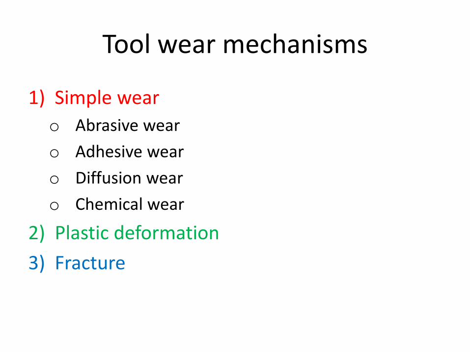
Tool wear mechanisms
1) Simple wear
o Abrasive wear
o Adhesive wear
o Diffusion wear
o Chemical wear
2) Plastic deformation
3) Fracture
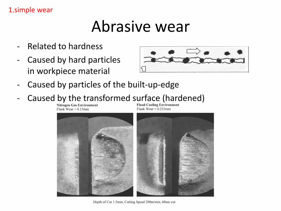
Abrasive wear- Related to hardness
- Caused by hard particles in workpiece material
- Caused by particles of the built-up-edge
- Caused by the transformed surface (hardened)
1.simple wear
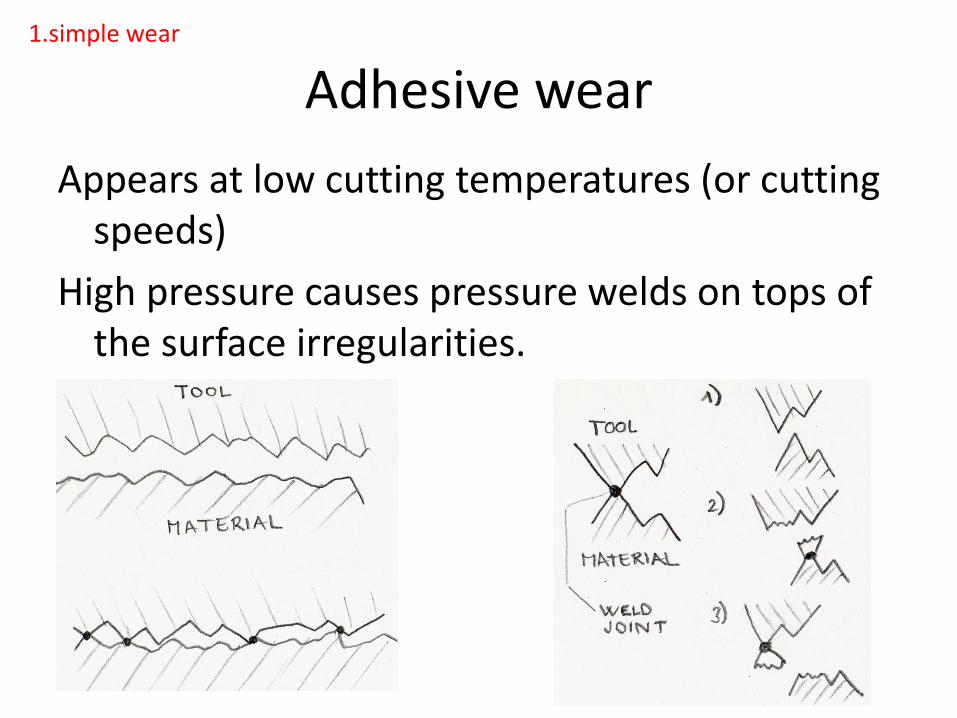
Adhesive wear
Appears at low cutting temperatures (or cutting speeds)
High pressure causes pressure welds on tops of the surface irregularities.
1.simple wear

Diffusion wear
•For diffusion is necessary certain temperature approx. 600°C
•NO Diffusion using carbon steels and HSS steel (low temperature)
•Diffusion using SC, ceramics, PCD and CBN.
•Diffusion is exchange of chemical elements between tool and material
1.simple wear
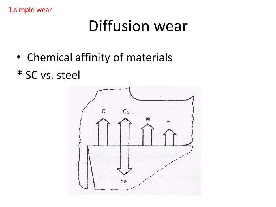
Diffusion wear
• Chemical affinity of materials
* SC vs. steel
1.simple wear
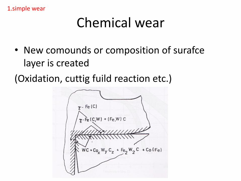
Chemical wear
• New comounds or composition of surafce layer is created
(Oxidation, cuttig fuild reaction etc.)
1.simple wear
Plastic deformation
All cutting tools, all materials – after some amountof tool wear the contact surface is too large
- Massive heat generation leeds to rapid temperature increase
- The hardness of material decreases (limitingtemperature)
- The high cutting force load leeds to loss ofgeometry and appearance of plasticdeformation(usually together with rapid wear ofcombined thermo-mechanical load)
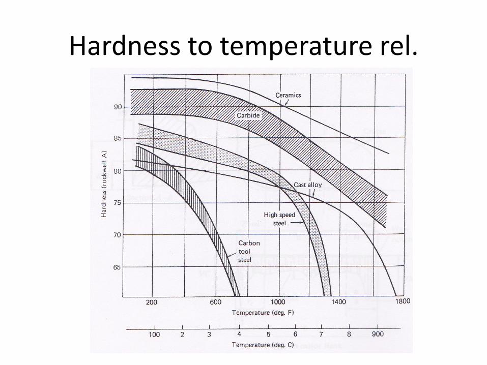
Hardness to temperature rel.
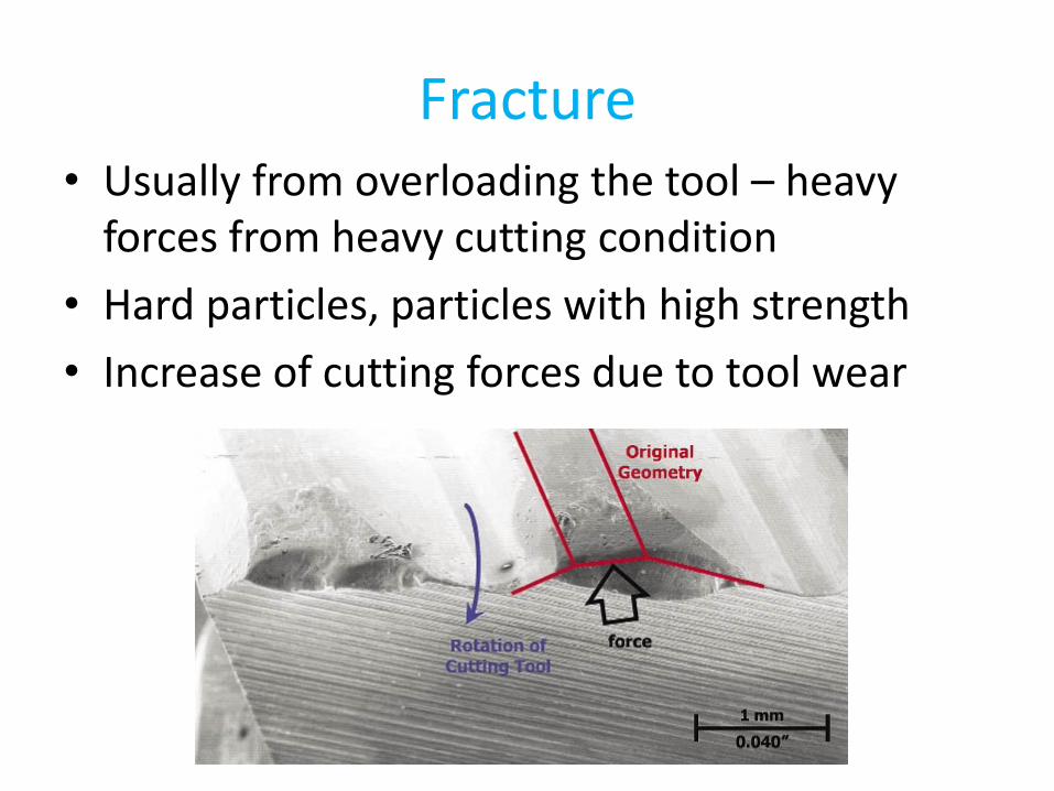
Fracture• Usually from overloading the tool – heavy
forces from heavy cutting condition
• Hard particles, particles with high strength
• Increase of cutting forces due to tool wear
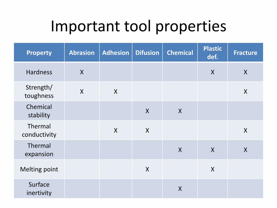
Important tool properties
Property Abrasion Adhesion Difusion ChemicalPlasticdef.
Fracture
Hardness X X X
Strength/toughness
X X X
Chemicalstability
X X
Thermalconductivity
X X X
Thermalexpansion
X X X
Melting point X X
Surfaceinertivity
X
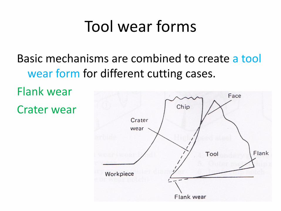
Tool wear forms
Basic mechanisms are combined to create a tool wear form for different cutting cases.
Flank wear
Crater wear
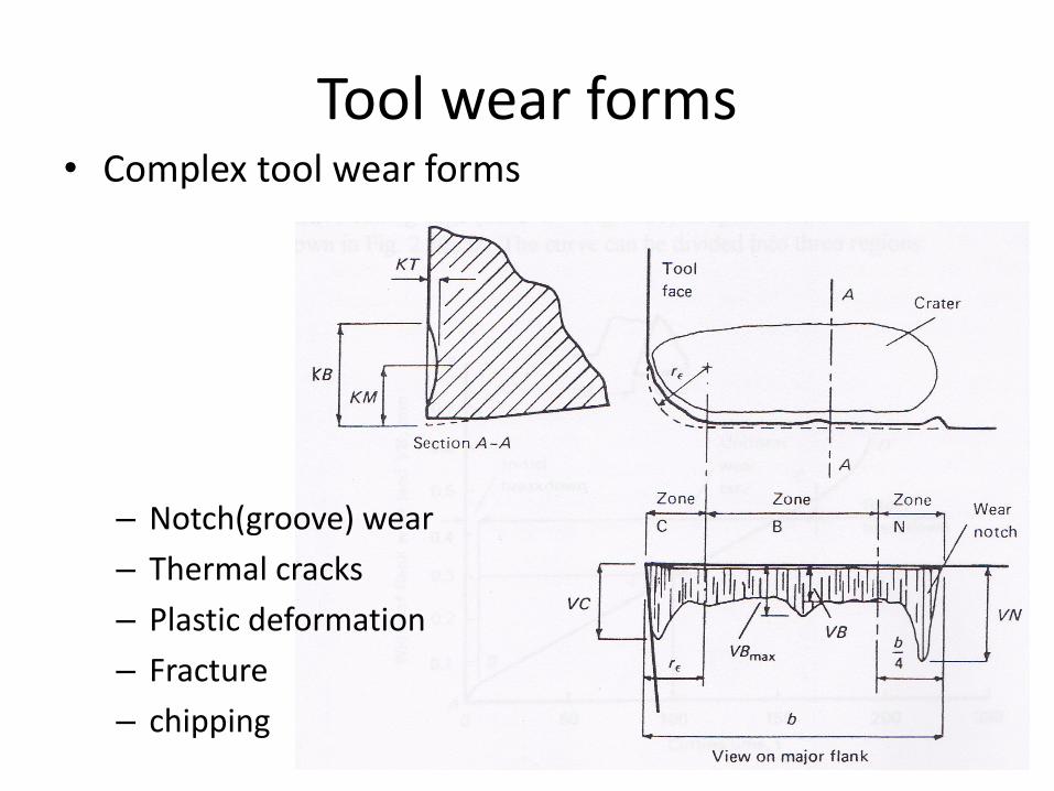
Tool wear forms• Complex tool wear forms
– Notch(groove) wear
– Thermal cracks
– Plastic deformation
– Fracture
– chipping
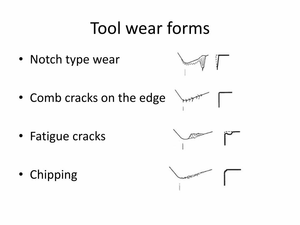
Tool wear forms
• Notch type wear
• Comb cracks on the edge
• Fatigue cracks
• Chipping

Tool wear types
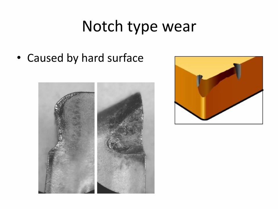
Notch type wear
• Caused by hard surface
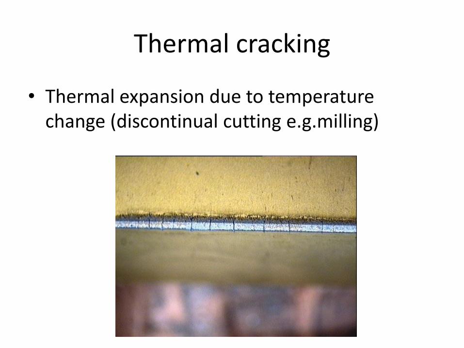
Thermal cracking
• Thermal expansion due to temperature change (discontinual cutting e.g.milling)
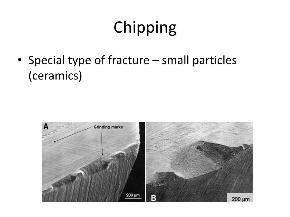
Chipping
• Special type of fracture – small particles (ceramics)
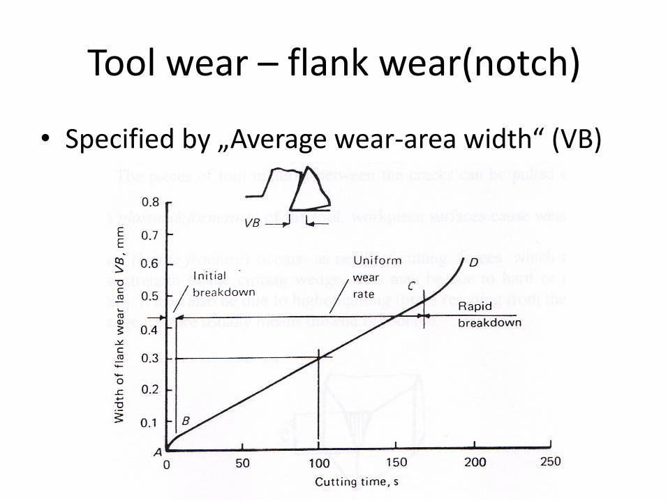
Tool wear – flank wear(notch)
• Specified by „Average wear-area width“ (VB)

Tool wear – flank wear(notch)
• Three regions
– AB – initial tool wear(rapid but decreasing)
– BC – uniform wear(uniform, slower)
– CD – rapid wear (fast and increasing)
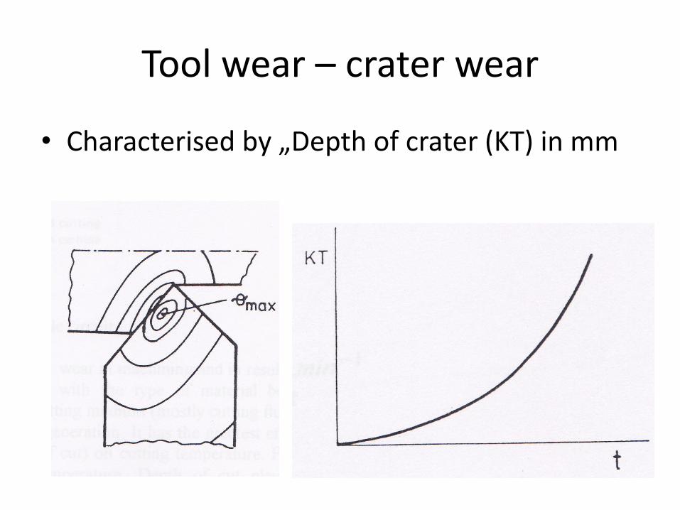
Tool wear – crater wear
• Characterised by „Depth of crater (KT) in mm
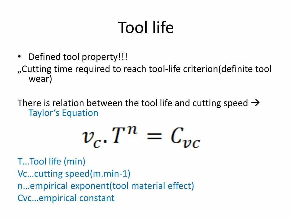
Tool life
• Defined tool property!!!„Cutting time required to reach tool-life criterion(definite tool
wear)
There is relation between the tool life and cutting speed Taylor‘s Equation
T…Tool life (min)Vc…cutting speed(m.min-1)n…empirical exponent(tool material effect)Cvc…empirical constant
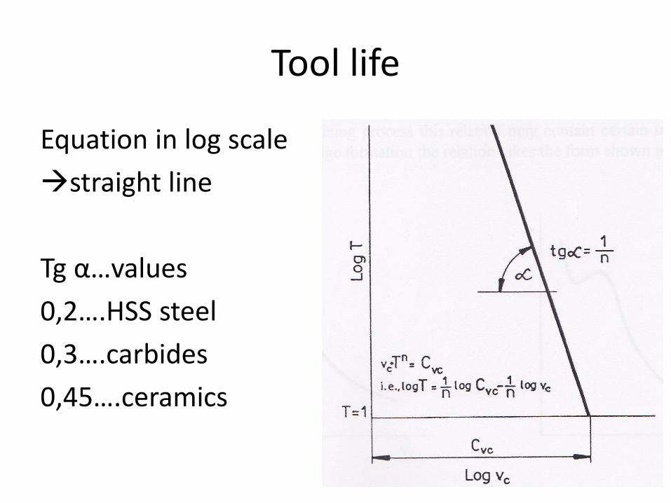
Tool life
Equation in log scale
straight line
Tg α…values
0,2….HSS steel
0,3….carbides
0,45….ceramics

Tool life
Experimental measurement
Changing cutting speed – VB measurement
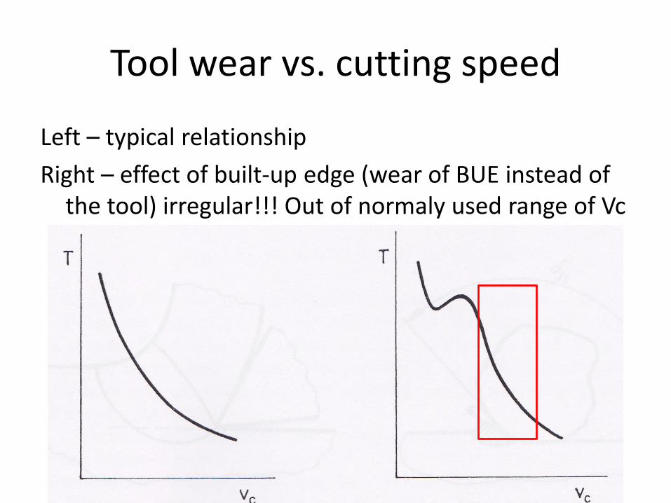
Tool wear vs. cutting speed
Left – typical relationship
Right – effect of built-up edge (wear of BUE instead ofthe tool) irregular!!! Out of normaly used range of Vc
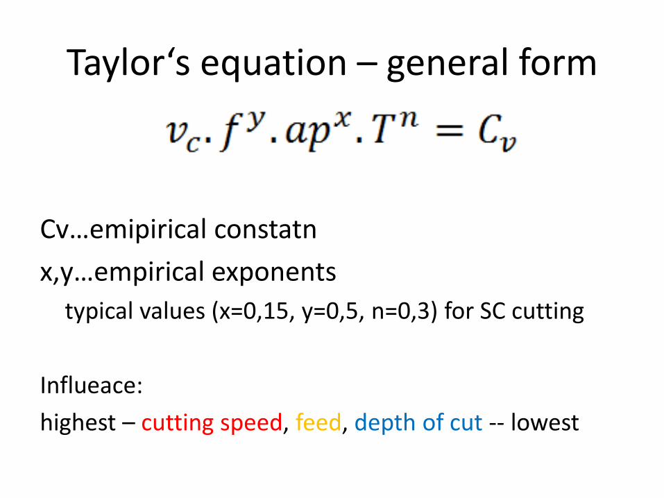
Taylor‘s equation – general form
Cv…emipirical constatn
x,y…empirical exponents
typical values (x=0,15, y=0,5, n=0,3) for SC cutting
Influeace:
highest – cutting speed, feed, depth of cut -- lowest
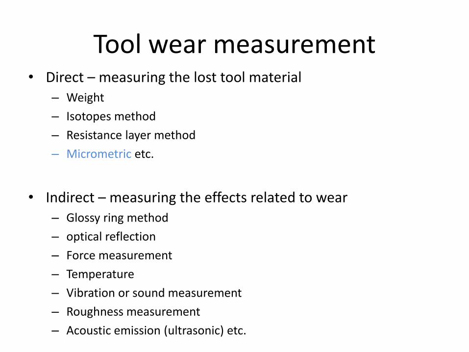
Tool wear measurement• Direct – measuring the lost tool material
– Weight
– Isotopes method
– Resistance layer method
– Micrometric etc.
• Indirect – measuring the effects related to wear– Glossy ring method
– optical reflection
– Force measurement
– Temperature
– Vibration or sound measurement
– Roughness measurement
– Acoustic emission (ultrasonic) etc.
Literature:
• BRINKSMEIER, E. : Monitoring of grinding wheel wear , Ananals of the CIRP, vol,1/1992, pp. 373
• GIUSTI, F. - SANTOCHI , M. – TANTUSSI, G.: On line sensing of flank and crater wear of cutting tools, CIRP, 1/1987, pp. 41
• GOMES DE OLIVEIRA , J.F. – DORNFELD, D.A. - WINTER , B.:Dimensionalcharacterization of grinding wheel surface through acoustic emission, Ananals of the CIRP, vol, 1/1994, p. 291
• ISO 3685 : 1990. Tool Life Testing With Single Point Turning Tools. 1990


![Influence of Cutting Factors on the Cutting Tool …metal cutting processes affected material properties and the tool wear. Sana [8] analyzed the 3-D transient temperature distributions](https://img.pdfslide.net/doc/110x75/5e715811c454d11ecf54717b/influence-of-cutting-factors-on-the-cutting-tool-metal-cutting-processes-affected.jpg)