Embed Size (px)
DESCRIPTION
Facts
Citation preview
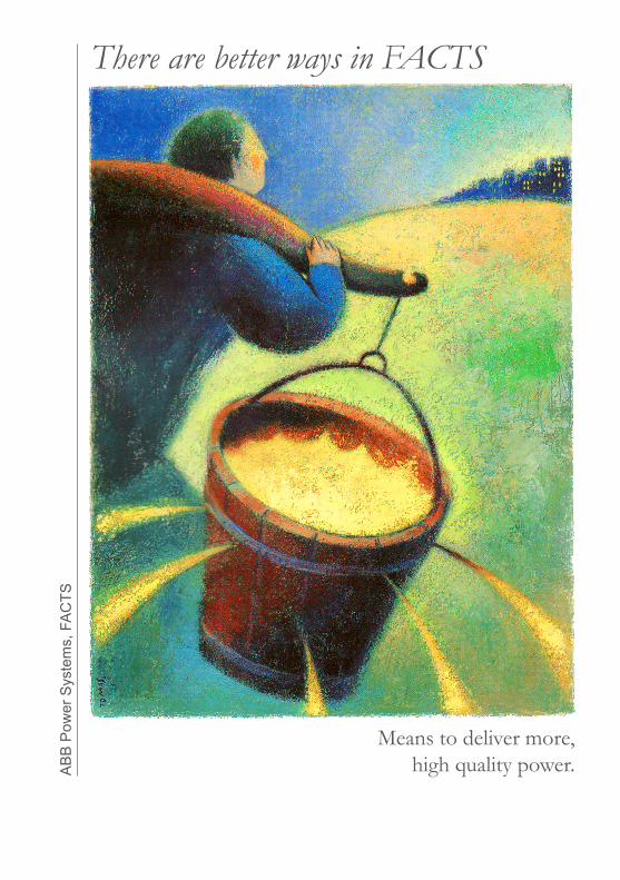
There are better ways in FACTS
Means to deliver more, high quality power.A
BB
Pow
er S
yste
ms,
FA
CTS

1. Reliable Power Supply for Everyone
2. Keeping the Network Stable
3. Voltage Stability
4. Reliable Power Transmission to Every Corner of the Network
5. Metal Industry: The Invisible EAF
6. Traction: A Demanding Load on The Grid
1.1 How Our Dependency on Electricity Arose1.2 Efficient Transportation of Electricity1.3 A Modern Power Supply Network
Contents
2.1 A Fragile Distribution Network2.2 Reactive Power2.3 Reactive Power Compensated in Different Ways
3.1 A Main Junction3.2 Old Synchronous Condensers Became Silent3.3 Near Downtown Generation Could Shut Down 3.4 Kanpur SVCs Save the Grid
5.1 Reactive Power Compensation in the Industry5.2 Increased Productivity for the Electric Arc Furnace5.3 Flicker Mitigation5.4 the Invisible Arc Furnace
6.1 Trains Take Power Between Phases6.2The Channel Tunnel Rail Link6.3 London Underground6.4 Svc Light for Active Filtering
4.1 Introduction4.2 Long Lines Get Shorter4.3 Parallel Lines4.4 Damping of Power Oscillations4.5 Undrground cable transmission
7. Grid Integration of Wind Farms7.1 Wind Farms7.2 Grid Integration of Windfarms7.3 Wind Power in Texas
9. STATCOM and SVC Light®
8. Static Var Compensation, SVC
10. Series Compensation SC, and TCSC
Contents
8.1 Introduction8.2 A Boiling Ocean Becomes a Mere Ripple8.3 Thyristor-Switched Capacitors TSC8.4 Thyristor-Controlled Reactor TCR8.5 Reactors and Capacitors Working Together
9.1 General9.2 Technology and Principle9.3 Statcom in Back-To-Back Configuration
10.1 Introduction10.2 Increased Capacity and Improved Voltage Stability 10.3 Increased Capacity and Maintained Angular Stability 10.4 Increased Capacity and Optimized Power Sharing Between Parallel
Circuits10.5 Over Voltage Protection of SC Banks10.6 Controllable Series Compensation, TCSC
There’s a better way 5
Reliable Power Supply for Everyone1.
1.1 How Our Dependency on Electricity Arose1.2 Efficient Transportation1.3 A Modern Power Supply Network
1.1 How Our Depen-dency on Electricity Arose
When we press a button or turn a switch we expect the lamp to light up, the motor to start or the heat to come on. If this does not happen we get irritated. Our accustomed behaviour pattern has been disrupted.
Just 150 years ago we would have been petrified if pressing a button had such results. We have become so dependent on electric power that we cannot even imagine a life without it.
But, someone may object, we have oil and petrol, after all. Our cars will continue to run and oil would still heat our houses.
Without electricity we would not be able to manufac-ture the cars of today and the oil-fired boiler would not work. In this manner electric power and control are wo-ven into every aspect of our present-day existence. Why electricity in particular; why not water, oil or gas? There are several reasons for this, but one of the most important is that electricity is easy to distribute. However, this has not always been the case.
Electric power - an expensive, roundabout way?When electric power was introduced in the latter half of the nineteenth century, there were certainly a great many who had doubts about its future. Why should a simple
Reliable Power Supply for Everyone1.
6 There’s a better way
Reliable Power Supply for Everyone1.steam engine giving direct drive be replaced by a steam engine with a generator, highly dangerous copper conduc-tors and an electric motor? Installation of such equipment presupposed that electric power was to be generated in the immediate vicinity of the user. The direct current that was generated had such a low voltage that long convey-ance distances were out of the question. The number of electricity subscribers a power station had were naturally limited by this.
For example, the electric power for the arc lighting at important cities’ railway stations was generated in a steam power station located just a few blocks away. Electricity was an exclusive and mostly inaccessible form of energy.
Modern Electric PowerHow could this exclusive form of energy become the most important building block in our modern society?
Around 1880 modern electric power was born. At several places around the world “three-phase alternating current” was introduced. Alternating current made it pos-sible to step up voltage to a high level and down again to a low voltage that could be easily handled. The high voltage made it possible to send electric power several kilometers without excessive losses and the toy railway at home on the kitchen floor no longer needed to have 110 volts be-tween its rails. Suddenly it was obvious how superior the principle of electrical distribution was.
It was no longer necessary to produce electricity in the neighbourhood. Electric power could be produced where the source of energy was to be found. Hydro-electric pow-er could be utilized by other consumers than saw mills and paper mills, and coal-fired power stations could be placed alongside harbours and coal pits. Electricity was available for everyone.
Available and Thus in DemandThe ready availability of electric power is not merely due to the fact that it can be distributed in a simple manner; it is also easy and convenient to use. Insert a plug in the wall and the motor will turn, the lamp will light up or the electric heater will glow. If oil is to be converted to corre-sponding forms of energy, unwieldy and evil-smelling ma-chinery and arrangements are necessary. It is true that the
1.1 How Our Depen-dency on Electric-ity Arose (Cont.)
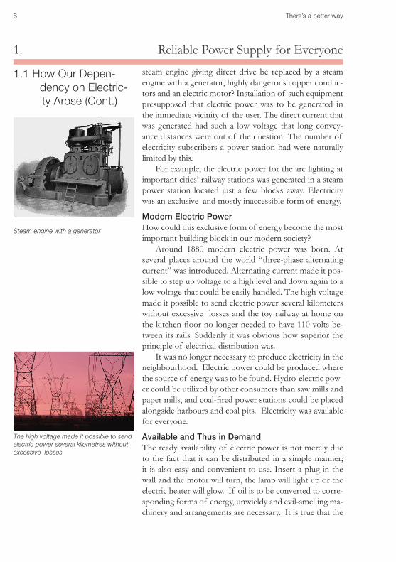
Steam engine with a generator
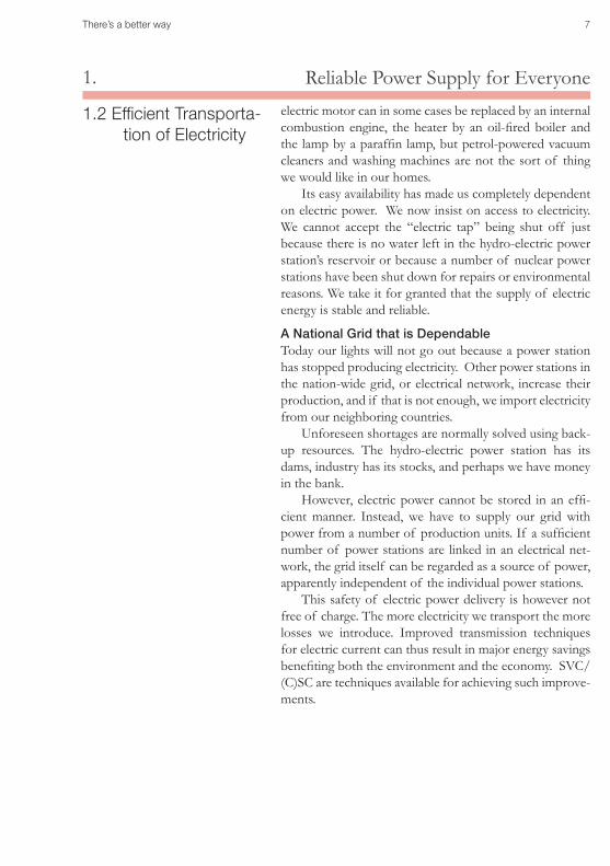
The high voltage made it possible to send electric power several kilometres without excessive losses
There’s a better way 7
Reliable Power Supply for Everyone1.electric motor can in some cases be replaced by an internal combustion engine, the heater by an oil-fired boiler and the lamp by a paraffin lamp, but petrol-powered vacuum cleaners and washing machines are not the sort of thing we would like in our homes.
Its easy availability has made us completely dependent on electric power. We now insist on access to electricity. We cannot accept the “electric tap” being shut off just because there is no water left in the hydro-electric power station’s reservoir or because a number of nuclear power stations have been shut down for repairs or environmental reasons. We take it for granted that the supply of electric energy is stable and reliable.
A National Grid that is DependableToday our lights will not go out because a power station has stopped producing electricity. Other power stations in the nation-wide grid, or electrical network, increase their production, and if that is not enough, we import electricity from our neighboring countries.
Unforeseen shortages are normally solved using back-up resources. The hydro-electric power station has its dams, industry has its stocks, and perhaps we have money in the bank.
However, electric power cannot be stored in an effi-cient manner. Instead, we have to supply our grid with power from a number of production units. If a sufficient number of power stations are linked in an electrical net-work, the grid itself can be regarded as a source of power, apparently independent of the individual power stations.
This safety of electric power delivery is however not free of charge. The more electricity we transport the more losses we introduce. Improved transmission techniques for electric current can thus result in major energy savings benefiting both the environment and the economy. SVC/(C)SC are techniques available for achieving such improve-ments.
1.2 Efficient Transporta-tion of Electricity
8 There’s a better way
Reliable Power Supply for Everyone1.
1.3 A Modern Power Supply Network
Sweden is a relatively cold, highly industrialized country. Both these factors make it very dependent on energy. Translating Sweden’s energy consumption into oil, every Swede would need 5.6 tonnes of crude oil per year. That is nearly 3 tonnes less than what is consumed in the U.S.A., but it is over 10 times as much as Africa uses.
Our imports of fossils fuels, however, are only 2.3 tonnes per person and year. The rest of our energy needs we cover through hydro power, nuclear power and burn-ing wood.
Oil Or ElectricityIf we had neither nuclear power nor hydro-electric power, we would have to replace these by burning gas, oil or coal. We would need to bring in another medium-sized super-tanker a day to our harbours, and in order to distribute this quantity of oil to industries and households, road tankers would have to trundle up and down our far-flung country with an extra two million loads a year.
All this energy is today transmitted in the form of electricity in high-voltage lines and cables. Electric power transmission is thus a real boon, especially to the environ-ment.
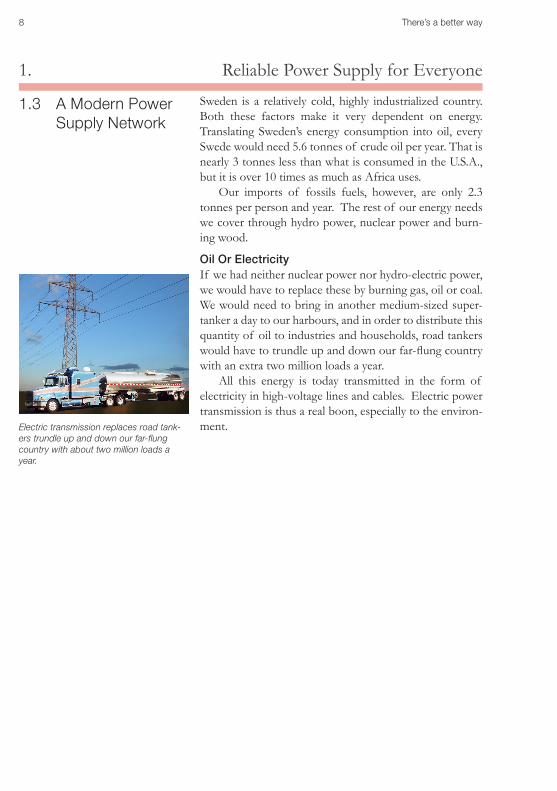
Electric transmission replaces road tank-ers trundle up and down our far-flung country with about two million loads a year.
There’s a better way 9
Reliable Power Supply for Everyone1.
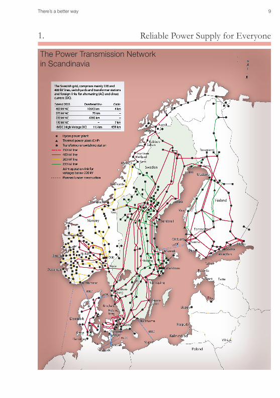
The Power Transmission Networkin Scandinavia
10 There’s a better way
2. Keeping the Network Stable
2.1 A Fragile Distribution Network2.2 Reactive Power2.3 Reactive Power Compensated in Different Ways
Keeping the Network Stable2.
Adam B. Brown enjoyed his new life without doubts and worries about electrical blackouts and with the posi-tive atmosphere that nowadays characterized his town. Even the approaching storm did not make him worry. He knew that nothing would interrupt the supply to his com-puter and with a steady office lighting there was nothing reminding him of the days of insecurity a year ago.
2.1 A Fragile Distribu-tion Network
Yes, it was a dreadful time for the town. They all suffered from the weak electricity supply.
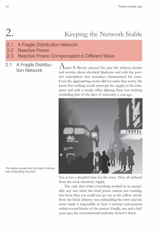
The only days when everything worked in an accept-able way was when the local power station was running, but those days you could not go out as the yellow smoke from the black chimney was embedding the town and the noise made it impossible to have a normal conversation within several blocks of the station. Finally, one and a half years ago, the environmental authority closed it down.
The yellow smoke from the black chimney was embedding the town.
There’s a better way 11
Keeping the Network Stable2.After that, the town’s energy supplier introduced measures that would “definitely” solve the problems.
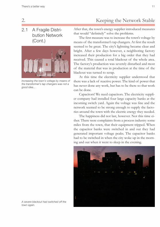
The first measure was to increase the town’s voltage by means of the transformer’s tap changers. At first the result seemed to be great. The city’s lightning became clear and bright. After a few days however, a neighboring factory increased their production for a big order that they had received. This caused a total blackout of the whole area. The factory’s production was severely disturbed and most of the material that was in production at the time of the blackout was turned to scrap.
At this time the electricity supplier understood that there was a lack of reactive power. The kind of power that has never done any work, but has to be there so that work can be done.
Capacitors! We need capacitors. The electricity suppli-er company had installed four large capacity banks at the incoming switch yard. Again the voltage was fine and the network seemed to be strong enough to supply the facto-ries around the town with the electric energy they needed.
The happiness did not last, however. Not this time ei-ther. There were complaints from a process industry some miles from the town, that their equipment tripped. When the capacitor banks were switched in and out they had generated important voltage peaks. The capacitor banks had to be switched in when the city woke up in the morn-ing and out when it went to sleep in the evening.
2.1 A Fragile Distri-bution Network (Cont.)
Increasing the town’s voltage by means of the transformer’s tap changers was not a good idea...
A severe blackout had switched off the town again.
12 There’s a better way
2. Keeping the Network StableAnother and the most important disappointment came with the storm over the neighbour mountains. At the time for the storm, the town’s network was heavily loaded by factories and air conditions and one of the external lines had reached it’s limit. A severe blackout had switched off the town again.
Now the Town Council had met and a stormy discus-sion on whose responsibility and how to find a definite solution on the problem occurred. The Town’s future was actually dependent on this, as there would not be any new industries settling down in an area where the electric net-work wasn’t reliable.
After some hours the discussions had calmed down and he, Adam B Brown, had got the responsibility to lead an investigation of the town’s alternative.
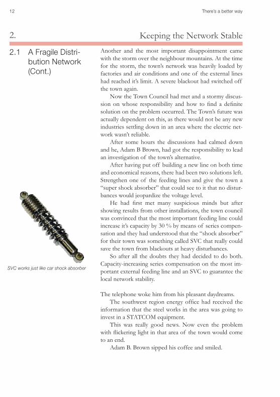
After having put off building a new line on both time and economical reasons, there had been two solutions left. Strengthen one of the feeding lines and give the town a “super shock absorber” that could see to it that no distur-bances would jeopardize the voltage level.
He had first met many suspicious minds but after showing results from other installations, the town council was convinced that the most important feeding line could increase it’s capacity by 30 % by means of series compen-sation and they had understood that the “shock absorber” for their town was something called SVC that really could save the town from blackouts at heavy disturbances.
So after all the doubts they had decided to do both. Capacity-increasing series compensation on the most im-portant external feeding line and an SVC to guarantee the local network stability.
The telephone woke him from his pleasant daydreams. The southwest region energy office had received the
information that the steel works in the area was going to invest in a STATCOM equipment.
This was really good news. Now even the problem with flickering light in that area of the town would come to an end.
Adam B. Brown sipped his coffee and smiled.
2.1 A Fragile Distri-bution Network (Cont.)
SVC works just like car shock absorber
There’s a better way 13
Keeping the Network Stable2.
Reactive Power Has Never Done Any Work Adam B. Brown’s town in last chapter was suffering from lack of reactive power and control of reactive power.
Reactive power has never done any work but without reactive power very little work will be done. Attempts to describe what reactive power is can make the reader more confused than enlightened.
This is not because Reactive Power is a badly defined quantity, it is rather because it is a quantity that does not exist in our real world.
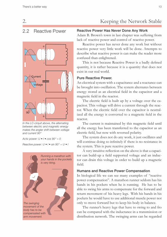
Pure Reactive Power. An electrical system with a capacitance and a reactance can be brought into oscillation. The system alternates between energy stored as an electrical field in the capacitor and a magnetic field in the reactor.
The electric field is built up by a voltage over the ca-pacitor. This voltage will drive a current through the reac-tor. When the electric field over the capacitor is neutral-ized all the energy is converted to a magnetic field in the reactor.
The current is maintained by this magnetic field until all the energy has been transferred to the capacitor as an electric field, but now with reversed polarity.
The system does not do any work, it just oscillates and will continue doing so infinitely if there is no resistance in the system. This is pure reactive power.
A very intuitive reflection on the above is that a capaci-tor can build-up a field supported voltage and an induc-tor can drain this voltage in order to build up a magnetic field.
Humans and Reactive Power CompensationIn biological life we can see many examples of “reactive power compensation”. A marathon runner seldom has his hands in his pockets when he is running. He has to be able to swing his arms to compensate for the forward and return movement of his heavy legs. With his hands in his pockets he would have to use additional muscle power not only to move forward but to keep his body in balance.
The runner’s heavy legs that have to swing to and fro can be compared with the inductance in a transmission or distribution network. The swinging arms can be regarded
The swinging movement of the body has to be compensated with arm movement.
Running a marathon with your hands in the pockets is very tiring.
In the LC-cirquit above, the alternating between electric and magnetic energy makes the anglar shift between voltage and current 90°
Activ power: U • I • cos 90° = 0
Reactive power: U • I • sin 90° = U • I
2.2 Reactive Power
+
+
-
-
Current
Voltage
90°
14 There’s a better way
2. Keeping the Network Stable
2.3 Reactive Power Compensated in Different Ways
A transmission line’s voltage level, stability and phase bal-ance can nearly always be maintained by designing the net-work with an ample margin. However, a network like this would be poorly utilized in normal service and costs would be unnecessarily high.
In reactive power compensation we have a means of control with which we can deal with certain eventuali-ties in a better manner. By adding and removing reactive power, we can get an intensively utilized network to cope with both load variations and other disturbances without any deterioration in the quality of the electric power pro-vided.
When alternating current has to be transmitted and converted into mechanical work, reactive power is con-sumed. If there is a shortage of reactive power, the volt-age will drop. The network voltage can thus be very effec-tively controlled by adding and removing reactive power.
Dynamic Shunt CompensationThe voltage drop over long lines can be kept down to a •reasonable level and voltage variations due to the load on the line varying during the day and during the year can be kept within reasonable limits.
Sudden over-voltages can be damped.•
Voltage collapses can be prevented.•
Lack of symmetry between the phases can be compen-•sated.
Distribution networks can cope with their local disturbanc-•es resulting from industries and network faults.
Series Compensation A transmission line has an inductive reactance, which can be reduced if a capacitor is connected in series to the line.With Series compensation we can achieve:
Improved transmission capability •
Reduced need to add reactive power.•
Reduced risk that generators and other synchronous ma-•chines loose synchronism in the event of a serious short circuit. (Angular stability)
The route of electric power into a transmission network is •controlled.
Improved voltage stability•
There’s a better way 15
Voltage Stability3.
Voltage stability
Norway is known for its hydro power resources. Im-portant resources at the location of some large hydro power stations does not mean that Norway’s power net-work doesn’t suffer from stability problems far out in its distant, radial branches.
In such locations as well as in meshed systems a distur-bance like a loss of an important power line or a short-cir-cuit can easily cause a blackout. The SVC is continuously supervising the voltage level and if there is a disturbance it quickly restores it.
A main junction of several 300 kV and 420 lines is situated at Sylling not far from Norway’s capital Oslo. In 1993 in the Sylling substation, an SVC was installed and connected to the 420 kV line in order to assure a reliable power supply.
The SVC replaced a large synchronous condenser, thereby upgrading the dynamic compensation to a lower
3.1 A Main Junction
3.3.1 A Main Junction3.2 Old Synchronous Condensers became Silent3.3 Near Downtown Generation could Shut Down 3.4 Kanpur SVCs Save the Grid
16 There’s a better way
Voltage Stability3.
3.1 A Main Junction(Cont.)
cost than for a new condensor. The task of the SVC is to assure dynamic voltage control on the heavily loaded south-eastern part of the grid close to Oslo and thereby:
preventing voltage collapses in the grid at operational •disturbances, such as loss of line or loss of generation.
preventing overvoltages at loss of load•
detecting and damping of active power oscillation •
There’s a better way 17
Voltage Stability3.
X
X
X
SVC
SVC115 kV69 kV
3.2 Old Synchronous Condensers be-came Silent
The power supply for San Francisco is a typical exam-ple of a network that has been built out in many steps comprising generation units within the area and various transmission lines and cables connecting to and from the Greater Bay Area.
Recent years San Francisco has suffered from severe pow-er supply disturbances and studies have shown that the area’s current transmission infrastructure is insufficient to accommodate anticipated load growth over the near fu-ture. As a result of the studies, a number of alternative solutions have been considered:
1. Doing nothing and live with the disturbances.•
2. Add means to stabilize and optimize the network at all •different kinds of load and supply situations.
3. Build an HVDC submarine link to support the area.•
4. Build new AC lines•
As the area needed a solution quickly alternative 2. was the solution to go for.
A key component in the work to stabilize and optimize the network was SVC.
Potrero
San Francisco
Newark
18 There’s a better way
Voltage Stability3.
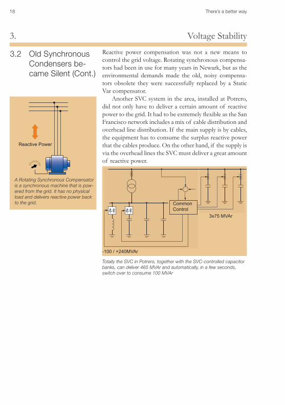
A Rotating Synchronous Compensator is a synchronous machine that is pow-ered from the grid. It has no physical load and delivers reactive power back to the grid.
Reactive Power
Reactive power compensation was not a new means to control the grid voltage. Rotating synchronous compensa-tors had been in use for many years in Newark, but as the environmental demands made the old, noisy compensa-tors obsolete they were successfully replaced by a Static Var compensator.
Another SVC system in the area, installed at Potrero, did not only have to deliver a certain amount of reactive power to the grid. It had to be extremely flexible as the San Francisco network includes a mix of cable distribution and overhead line distribution. If the main supply is by cables, the equipment has to consume the surplus reactive power that the cables produce. On the other hand, if the supply is via the overhead lines the SVC must deliver a great amount of reactive power.
-100 / +240MVAr
3x75 MVAr
Totally the SVC in Potrero, together with the SVC-controlled capacitor banks, can deliver 465 MVAr and automatically, in a few seconds, switch over to consume 100 MVAr
3.2 Old Synchronous Condensers be-came Silent (Cont.)
Common Control
There’s a better way 19
Voltage Stability3.
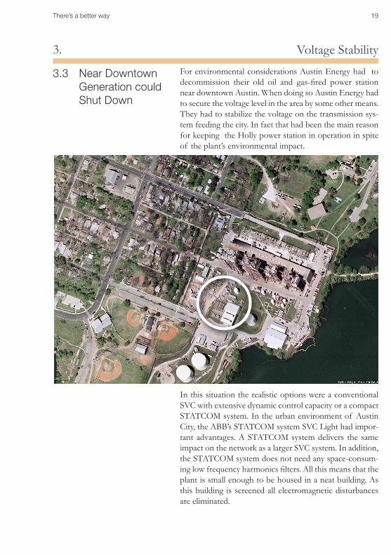
For environmental considerations Austin Energy had to decommission their old oil and gas-fired power station near downtown Austin. When doing so Austin Energy had to secure the voltage level in the area by some other means. They had to stabilize the voltage on the transmission sys-tem feeding the city. In fact that had been the main reason for keeping the Holly power station in operation in spite of the plant’s environmental impact.
In this situation the realistic options were a conventional SVC with extensive dynamic control capacity or a compact STATCOM system. In the urban environment of Austin City, the ABB’s STATCOM system SVC Light had impor-tant advantages. A STATCOM system delivers the same impact on the network as a larger SVC system. In addition, the STATCOM system does not need any space-consum-ing low frequency harmonics filters. All this means that the plant is small enough to be housed in a neat building. As this building is screened all electromagnetic disturbances are eliminated.
3.3 Near Downtown Generation could Shut Down
20 There’s a better way
Voltage Stability3.
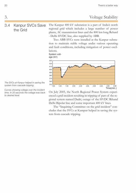
3.4 Kanpur SVCs Save the Grid
The Kanpur 400 kV substation is a part of India’s north regional grid which includes a large number of power plants, AC-transmission lines and the 800 km long Rehard - Delhi HVDC line, also supplied by ABB.
Two ABB SVCs were installed at the Kanpur substa-tion to maintain stable voltage under various operating and fault conditions, including mitigation of power oscil-lations.
1:00 1:20 1:40 2:00 2:20 2:40 3:00 3:20 3:40 4:00
430
420
410
400
490
380
370
360
350
On July 2005, the North Regional Power System experi-enced a grid incident resulting in tripping of part of the re-gional system named Dadri, outage of the HVDC Rihand Delhi Bipolar line and some important 400 kV lines.
The “Inquiring Committee on the grid incident” con-cludes that the SVCs at Kampur helped in saving the sys-tem from cascade tripping.
System volt-age (kV)
Time(min.)
The SVCs at Kanpur helped in saving the system from cascade tripping.
Curves showing voltage over the incident time. In 20 seconds the voltage was back to desired level.
There’s a better way 21
Reliable Power Transmission to Every Corner of the Network4.
Reliable Power Transmission to Every Cor-ner of the Network
4.1 Introduction A line that is to transmit electric power over long dis-tances cannot do this without suffering losses.
Resistance losses always occur when we transmit cur-rent. Transmitting alternating current, a lack of reactive power can gives rise to important voltage drops .
A small deviation from nominal voltage is often ac-ceptable, but even that can cause long-term consequences for the service life of electric motors for instance. If the deviation increases too much, there could be a potential risk for voltage collapse.
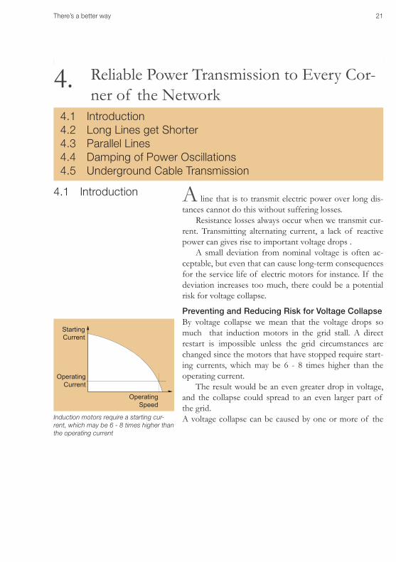
Preventing and Reducing Risk for Voltage CollapseBy voltage collapse we mean that the voltage drops so much that induction motors in the grid stall. A direct restart is impossible unless the grid circumstances are changed since the motors that have stopped require start-ing currents, which may be 6 - 8 times higher than the operating current.
The result would be an even greater drop in voltage, and the collapse could spread to an even larger part of the grid. A voltage collapse can be caused by one or more of the
4.1 Introduction4.2 Long Lines get Shorter4.3 Parallel Lines4.4 Damping of Power Oscillations4.5 Underground Cable Transmission
4.
Starting Current
Operating Current
Operating Speed
Induction motors require a starting cur-rent, which may be 6 - 8 times higher than the operating current
22 There’s a better way
Reliable Power Transmission to Every Corner of the Network4.following circumstances:
High transmission reactance•
A supply line drops out•
Insufficient capacity to add reactive power•
The load consists of too many asynchronous motors•
Automatic tap-changers on distribution transformers•
Excitation limiters on synchronous machines•
When a voltage collapse occurs, depending on the causes, it can take from fractions of a second up to half an hour before the normal value of the voltage is reached.
The voltage drop can be compensated by adding reac-tive power. The reactive power can be added at various spots and using different kinds of apparatus.
If there is risk of a collapse, but one which develops slowly, circuit-breaker-switched shunt capacitors are gen-erally sufficient.
If the anticipated collapse is estimated to take place at a faster rate, thyristor-controlled SVCs are the obvious choice.
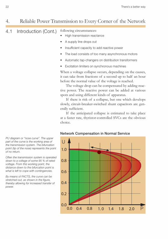
Network Compensation in Normal Service
4.1 Introduction (Cont.)
1.0
1.8 2.0
0.8
1.4
0.6
1. 0
0.4
0.8
0.2
0.40.0
0.0 P
UPU diagram or “nose curve”. The upper part of the curve is the working area of the transmission system. The bifurcation point (tip of the nose) represents the point of no return.
Often the transmission system is operated down to a voltage of some 95 % of rated voltage. From this working point, the distance down to the bifurcation point is what is left to cope with contingencies.
By means of FACTS, the curve can be stretched out, as shown in the figure, thereby allowing for increased transfer of power.
There’s a better way 23
Reliable Power Transmission to Every Corner of the Network4.
G
G
U1
U2
UN
DistanceUncompensated voltage
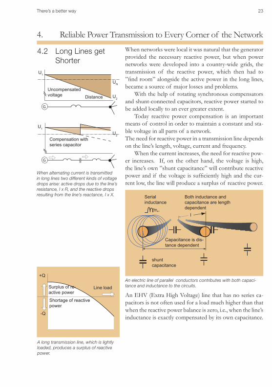
When networks were local it was natural that the generator provided the necessary reactive power, but when power networks were developed into a country-wide grids, the transmission of the reactive power, which then had to ”find room” alongside the active power in the long lines, became a source of major losses and problems.
With the help of rotating synchronous compensators and shunt-connected capacitors, reactive power started to be added locally to an ever greater extent.
Today reactive power compensation is an important means of control in order to maintain a constant and sta-ble voltage in all parts of a network. The need for reactive power in a transmission line depends on the line’s length, voltage, current and frequency.
When the current increases, the need for reactive pow-er increases. If, on the other hand, the voltage is high, the line’s own ”shunt capacitance” will contribute reactive power and if the voltage is sufficiently high and the cur-rent low, the line will produce a surplus of reactive power.
4.2 Long Lines get Shorter
shunt capacitance
Serial inductance
An electric line of parallel conductors contributes with both capaci-tance and inductance to the circuits.
Capacitance is dis-tance dependent
Both inductance and capacitance are length dependent
l
Compensation with series capacitor
U1
U2
When alternating current is transmitted in long lines two different kinds of voltage drops arise: active drops due to the line’s resistance, I x R, and the reactive drops resulting from the line’s reactance, I x X.
An EHV (Extra High Voltage) line that has no series ca-pacitors is not often used for a load much higher than that when the reactive power balance is zero, i.e., when the line’s inductance is exactly compensated by its own capacitance.
Line load
A long transmission line, which is lightly loaded, produces a surplus of reactive power.
+Q
-Q
Shortage of reactive power
Surplus of re-active power
24 There’s a better way
Reliable Power Transmission to Every Corner of the Network4.
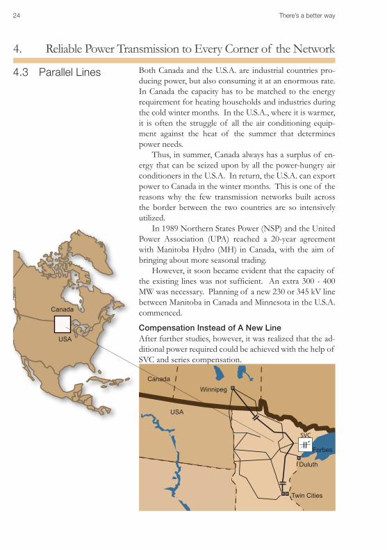
4.3 Parallel Lines Both Canada and the U.S.A. are industrial countries pro-ducing power, but also consuming it at an enormous rate. In Canada the capacity has to be matched to the energy requirement for heating households and industries during the cold winter months. In the U.S.A., where it is warmer, it is often the struggle of all the air conditioning equip-ment against the heat of the summer that determines power needs.
Thus, in summer, Canada always has a surplus of en-ergy that can be seized upon by all the power-hungry air conditioners in the U.S.A. In return, the U.S.A. can export power to Canada in the winter months. This is one of the reasons why the few transmission networks built across the border between the two countries are so intensively utilized.
In 1989 Northern States Power (NSP) and the United Power Association (UPA) reached a 20-year agreement with Manitoba Hydro (MH) in Canada, with the aim of bringing about more seasonal trading.
However, it soon became evident that the capacity of the existing lines was not sufficient. An extra 300 - 400 MW was necessary. Planning of a new 230 or 345 kV line between Manitoba in Canada and Minnesota in the U.S.A. commenced.
Compensation Instead of A New LineAfter further studies, however, it was realized that the ad-ditional power required could be achieved with the help of SVC and series compensation.
SVC
Twin Cities
Winnipeg
Canada
USA
Duluth
Forbes
USA
Canada
There’s a better way 25
Reliable Power Transmission to Every Corner of the Network4.
4.3 Parallel Lines (Cont.)
SVC improves the generation and transmission system’s dynamic response to network disturbances. It also pro-vides improvement during steady-state conditions by sup-plying adequate reactive power support. With the SVC in operation, the power transmission capability of the trans-mission system has been increased by some 200 MW.
Without SVC, the power transmission capability of the NSP network would be severely limited, either due to excessive voltage fluctuations following certain fault situations in the underlying 345 kV system, or to severe overvoltages at loss of supply from HVDC lines coming from Manitoba.
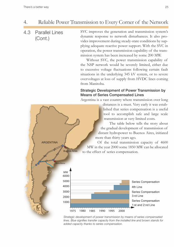
Strategic Development of Power Transmission by Means of Series Compensated LinesArgentina is a vast country where transmission over long
distances is a must. Very early it was estab-lished that series compensation is a useful tool to accomplish safe and large scale transmission at very limited costs.
The table below tells the story about the gradual development of transmission of
distant hydropower to Buenos Aires, initiated more than thirty years ago.
Of the total transmission capacity of 4600 MW in the year 2000 some 1850 MW can be allocated
to the effect of series compensation.Buenos Aires
Bahia Blanca
ARGENTINA
1975 1980 1985 1990 1995 2000
1000
2000
3000
4000
5000
6000MW
3:rd Line
1:st and 2:nd Line
4th Line
Series Compensation
Series Compensation
Series Compensation
Strategic development of power transmission by means of series compensated lines. Blue signifies transfer capacity from the installed line and brown stands for added capacity thanks to series compensation.
26 There’s a better way
Reliable Power Transmission to Every Corner of the Network4.
4.4 Damping of Power Oscillations (POD) (Cont.)
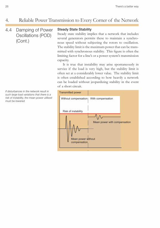
If disturbances in the network result in such large load variations that there is a risk of instability, the mean power utilised must be lowered.
Transmitted power
Mean power with compensation
Mean power without compensation
Risk of instability
Without compensation With compensation
Steady State StabilitySteady state stability implies that a network that includes several generators permits these to maintain a synchro-nous speed without subjecting the rotors to oscillation. The stability limit is the maximum power that can be trans-mitted with synchronous stability. This figure is often the limiting factor for a line’s or a power system’s transmission capacity.
It is true that instability may arise spontaneously in service if the load is very high, but the stability limit is often set at a considerably lower value. The stability limit is often established according to how heavily a network can be loaded without jeopardizing stability in the event of a short circuit.
There’s a better way 27
Reliable Power Transmission to Every Corner of the Network4.
4.4 Damping of Power Oscillations (POD) (Cont.)
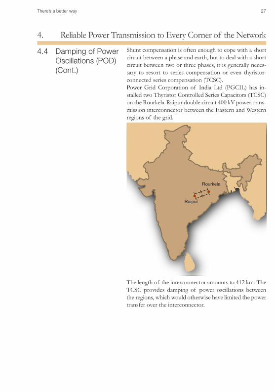
Shunt compensation is often enough to cope with a short circuit between a phase and earth, but to deal with a short circuit between two or three phases, it is generally neces-sary to resort to series compensation or even thyristor-connected series compensation (TCSC).Power Grid Corporation of India Ltd (PGCIL) has in-stalled two Thyristor Controlled Series Capacitors (TCSC) on the Rourkela-Raipur double circuit 400 kV power trans-mission interconnector between the Eastern and Western regions of the grid.
The length of the interconnector amounts to 412 km. The TCSC provides damping of power oscillations between the regions, which would otherwise have limited the power transfer over the interconnector.
Rourkela
Raipur
28 There’s a better way
Reliable Power Transmission to Every Corner of the Network4.
X (Ohm)TCS C-reactance
0 20 40 60-40
-30
-20
-10
0
10
time (s ec)
P line (MW)
0 20 40 600
200
400
600
800
time (s ec)
No TCS C P OD active
0 20 40 600
200
400
600
800
time (s ec)
P line (MW)North TCS C P OD active
4.4 Damping of Power Oscillations (POD) (Cont.)
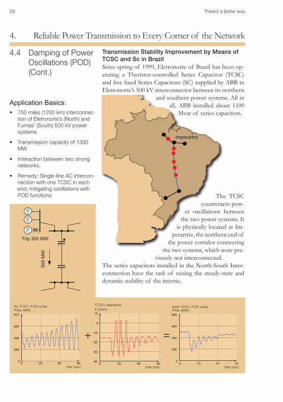
Transmission Stability Improvement by Means of TCSC and Sc in BrazilSince spring of 1999, Eletronorte of Brazil has been op-erating a Thyristor-controlled Series Capacitor (TCSC) and five fixed Series Capacitors (SC) supplied by ABB in Eletronorte’s 500 kV interconnector between its northern
and southern power systems. All in all, ABB installed about 1100
Mvar of series capacitors.
The TCSC counteracts pow-
er oscillations between the two power systems. It
is physically located at Im-perartriz, the northern end of
the power corridor connecting the two systems, which were pre-
viously not interconnected. The series capacitors installed in the North-South Inter-connection have the task of raising the steady-state and dynamic stability of the intertie.
750 miles (1200 km) interconnec-•tion of Eletronorte’s (North) and Furnas’ (South) 500 kV power systems
Transmission capacity of 1300 •MW
Interaction between two strong •networks.
Remedy: Single-line AC intercon-•nection with one TCSC in each end, mitigating oscillations with POD functions
G
G
G
500
MW
Trip 300 MW
+ =
Imperartriz
Application Basics:
There’s a better way 29
Reliable Power Transmission to Every Corner of the Network4.
4.5 Underground Cable Transmis-sion
Long Underground and Submarine CablesA ground or submarine cable produces 20 to 40 times more reactive power than an overhead line for the same voltage. Consequently, considerable amounts of reactive power have to be absorbed, especially at low load.
A common solution is compensation with shunt reac-tors, and excellent results can be achieved with thyristor-controlled shunt reactors (TCR). A thyristor-controlled shunt reactor is so fast that the voltage can be kept con-stant without apparent disturbance despite large variations in transmitted power.
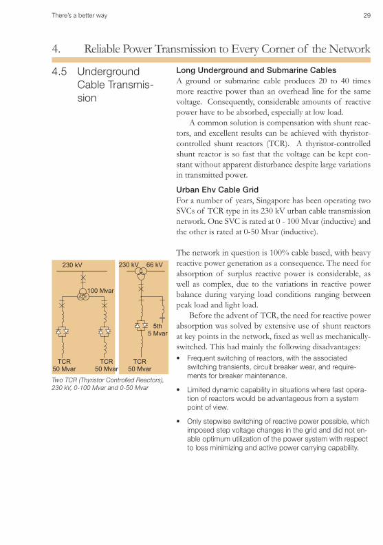
Urban Ehv Cable GridFor a number of years, Singapore has been operating two SVCs of TCR type in its 230 kV urban cable transmission network. One SVC is rated at 0 - 100 Mvar (inductive) and the other is rated at 0-50 Mvar (inductive).
The network in question is 100% cable based, with heavy reactive power generation as a consequence. The need for absorption of surplus reactive power is considerable, as well as complex, due to the variations in reactive power balance during varying load conditions ranging between peak load and light load.
Before the advent of TCR, the need for reactive power absorption was solved by extensive use of shunt reactors at key points in the network, fixed as well as mechanically-switched. This had mainly the following disadvantages:
Frequent switching of reactors, with the associated •switching transients, circuit breaker wear, and require-ments for breaker maintenance.
Limited dynamic capability in situations where fast opera-•tion of reactors would be advantageous from a system point of view.
Only stepwise switching of reactive power possible, which •imposed step voltage changes in the grid and did not en-able optimum utilization of the power system with respect to loss minimizing and active power carrying capability.
Two TCR (Thyristor Controlled Reactors), 230 kV, 0-100 Mvar and 0-50 Mvar
230 kV 230 kV 66 kV
5th5 Mvar
TCR50 Mvar
TCR50 Mvar
TCR50 Mvar
100 Mvar
30 There’s a better way
Reliable Power Transmission to Every Corner of the Network4.
4.5 Underground Cable Transmis-sion (Cont).
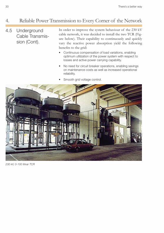
In order to improve the system behaviour of the 230 kV cable network, it was decided to install the two TCR (Fig-ure below). Their capability to continuously and quickly vary the reactive power absorption yield the following benefits to the grid:
Continuous compensation of load variations, enabling •optimum utilization of the power system with respect to losses and active power carrying capability.
No need for circuit breaker operations, enabling savings •on maintenance costs as well as increased operational reliability.
Smooth grid voltage control.•
230 kV, 0-100 Mvar TCR
without the need
There’s a better way 31
Metal Industry: The Invisible Electric Arc Furnace5.
Metal Industry: The Invisible Electric Arc Furnace
Heavy industries often purchase power direct from the transmission network, at 70 to 130 kV or even higher. Agreements with power utilities include a maximum take-off of both active and reactive power.
If these limits are exceeded, a penalty fee is imposed. Thus heavy industry can put a price on reactive power.
Special Needs for Compensation in IndustryIn the pulp and paper industry and the steel industry there are certain very special loads that require specially matched reactive power compensation. A rolling mill is often driven by large thyristor-controlled DC or cycloconverter drives.
10 to 50 thyristor-controlled converters may be the source of power for a paper machine. Thyristor convert-ers that provide full current at low machine speed use up large quantities of reactive power. When at full speed, however, the reactive power consumption is practically zero. For large rolling mills, SVCs must be resorted to.
Arc furnaces require access to large amounts of reac-tive power. An arc furnace also gives rise to unsymmetri-cal loading and therefore has to be compensated phase by phase.
When an induction motor starts up, it can use 6 to 8 times more current than when in normal operation.
Industrial networks with large induction motors are therefore frequently equipped with special shunt-connect-ed starting capacitors.
In addition, if the motors are sufficiently large and start sufficiently often in a weak network, thyristor-controlled compensation by means of SVC is often necessary.
5.1 Reactive Power Compensation in the Industry
5.1 Reactive Power Compensation in Industry5.2 Increased Productivity for the Electric Arc Furnace5.3 Flicker Mitigation5.4 The Invisible Arc Furnace
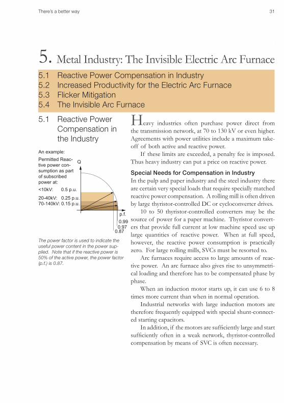
An example:
The power factor is used to indicate the useful power content in the power sup-plied. Note that if the reactive power is 50% of the active power, the power factor (p.f.) is 0.87.
Q
p.f.0.990.97
0.87
Permitted Reac-tive power con-sumption as part of subscribed power at:<10kV: 0.5 p.u.
20-40kV: 0.25 p.u.70-140kV: 0.15 p.u.
5.
32 There’s a better way
Metal Industry: The Invisible Electric Arc Furnace5.
5.1 Reactive Power Compensation in the Industry (Cont.)
Heavy industry is often a major consumer of reactive power and in an effort to compensate at the point of com-mon coupling rather than load the line with the transmis-sion of reactive power, compensation locally is arranged as far as possible.
In process industries there is normally a reactive base load consisting of a very large number of AC motors.
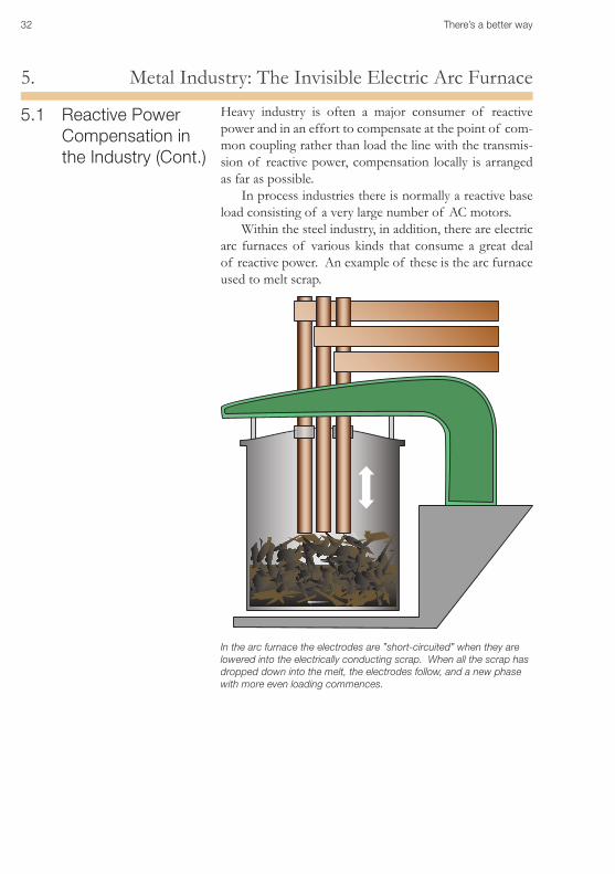
Within the steel industry, in addition, there are electric arc furnaces of various kinds that consume a great deal of reactive power. An example of these is the arc furnace used to melt scrap.
In the arc furnace the electrodes are ”short-circuited” when they are lowered into the electrically conducting scrap. When all the scrap has dropped down into the melt, the electrodes follow, and a new phase with more even loading commences.
There’s a better way 33
Metal Industry: The Invisible Electric Arc Furnace5.
Arc furnace
The thyristor bridge in the SVC installation controls the total reactive power; it also distributes it between the phases and in a phase-wise manner for the sake of phase symmetry.
5.2 Increased Produc-tivity in the Electric Arc Furnace
To parry the rapidly fluctuating consumption of reactive power of arc furnaces, an equally rapid compensating de-vice is required. This is the task of the SVC. The purpose of the SVC is to:
Keep a good and stable power factor at the point of •common connection, independently of the reactive power fluctuations from the furnace loads.
Reduce flicker at the point of common connection to ac-•ceptable levels.
Filter the harmonics generated by the furnaces.•
Stabilise the system voltage at the EAF load bus.•
Stabilising the voltage at the EAF load bus at a high level usually means an increase of active power into the furnace, compared to the case without SVC. This in turn opens up for increased productivity of the metallurgical process.
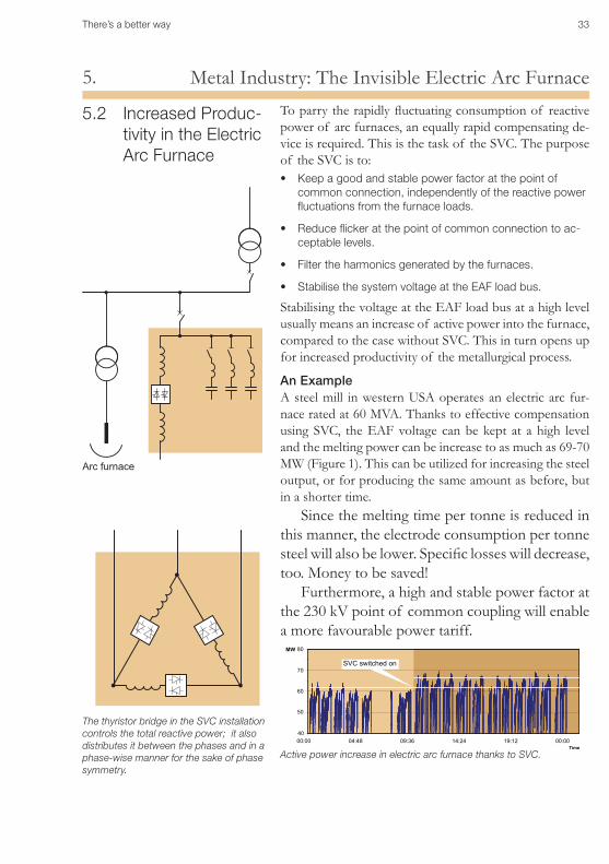
An ExampleA steel mill in western USA operates an electric arc fur-nace rated at 60 MVA. Thanks to effective compensation using SVC, the EAF voltage can be kept at a high level and the melting power can be increase to as much as 69-70 MW (Figure 1). This can be utilized for increasing the steel output, or for producing the same amount as before, but in a shorter time.
Since the melting time per tonne is reduced in this manner, the electrode consumption per tonne steel will also be lower. Specific losses will decrease, too. Money to be saved!
Furthermore, a high and stable power factor at the 230 kV point of common coupling will enable a more favourable power tariff.
Active power increase in electric arc furnace thanks to SVC.
40
50
60
70
80
00:00 04:48 09:36 14:24 19:12 00:00Time
MW
SVC switched on
34 There’s a better way
Metal Industry: The Invisible Electric Arc Furnace5.
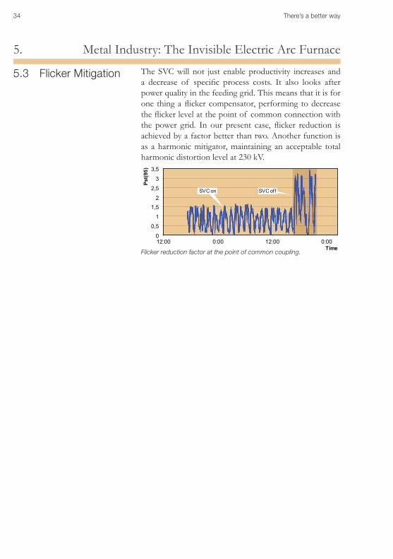
5.3 Flicker Mitigation The SVC will not just enable productivity increases and a decrease of specific process costs. It also looks after power quality in the feeding grid. This means that it is for one thing a flicker compensator, performing to decrease the flicker level at the point of common connection with the power grid. In our present case, flicker reduction is achieved by a factor better than two. Another function is as a harmonic mitigator, maintaining an acceptable total harmonic distortion level at 230 kV.
0
0,5
1
1,52
2,5
3
3,5
12:00 0:00 12:00 0:00Time
Pst(9
5)
SVC on SVC off
Flicker reduction factor at the point of common coupling.
There’s a better way 35
Metal Industry: The Invisible Electric Arc Furnace5.
5.4 The Invisible Arc Furnace
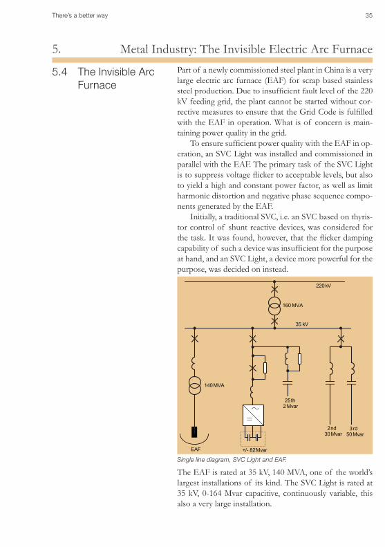
Part of a newly commissioned steel plant in China is a very large electric arc furnace (EAF) for scrap based stainless steel production. Due to insufficient fault level of the 220 kV feeding grid, the plant cannot be started without cor-rective measures to ensure that the Grid Code is fulfilled with the EAF in operation. What is of concern is main-taining power quality in the grid.
To ensure sufficient power quality with the EAF in op-eration, an SVC Light was installed and commissioned in parallel with the EAF. The primary task of the SVC Light is to suppress voltage flicker to acceptable levels, but also to yield a high and constant power factor, as well as limit harmonic distortion and negative phase sequence compo-nents generated by the EAF.
Initially, a traditional SVC, i.e. an SVC based on thyris-tor control of shunt reactive devices, was considered for the task. It was found, however, that the flicker damping capability of such a device was insufficient for the purpose at hand, and an SVC Light, a device more powerful for the purpose, was decided on instead.
EAF +/- 82 Mvar
25th2 Mvar
220 kV
160 MVA
2nd30 Mvar
3rd50 Mvar
140 MVA
35 kV
Single line diagram, SVC Light and EAF.
The EAF is rated at 35 kV, 140 MVA, one of the world’s largest installations of its kind. The SVC Light is rated at 35 kV, 0-164 Mvar capacitive, continuously variable, this also a very large installation.
36 There’s a better way
Metal Industry: The Invisible Electric Arc Furnace5.
5.4 The Invisible Arc Furnace (Cont.)
The SVC Light (Figure, previous page) is based on a volt-age source converter (VSC), built up of IGBTs (insulated gate bipolar transistors). A single converter is utilised, thereby avoiding all paralleling of devices. The converter is directly connected to the 35 kV EAF bus, without any need for a step-down transformer or other complex mag-netic interfaces. As DC link, high voltage DC capacitors are utilized. This all ensures a simple and compact build-up. The SVC Light control scheme is based on pulse-width modulation (PWM), thereby ensuring minimum need for harmonic filtering.
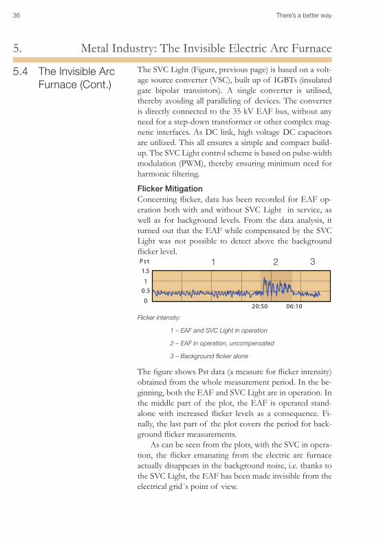
Flicker Mitigation Concerning flicker, data has been recorded for EAF op-eration both with and without SVC Light in service, as well as for background levels. From the data analysis, it turned out that the EAF while compensated by the SVC Light was not possible to detect above the background flicker level.
Flicker intensity:
1 – EAF and SVC Light in operation
2 – EAF in operation, uncompensated
3 – Background flicker alone
1 2 3Ps t
0
0.51
1.5
20:50 06:10
The figure shows Pst data (a measure for flicker intensity) obtained from the whole measurement period. In the be-ginning, both the EAF and SVC Light are in operation. In the middle part of the plot, the EAF is operated stand-alone with increased flicker levels as a consequence. Fi-nally, the last part of the plot covers the period for back-ground flicker measurements.
As can be seen from the plots, with the SVC in opera-tion, the flicker emanating from the electric arc furnace actually disappears in the background noise, i.e. thanks to the SVC Light, the EAF has been made invisible from the electrical grid´s point of view.
There’s a better way 37
Traction: A Demanding Load on the Grid6.
Traction: a demanding load on the grid6.6.1 Trains Take Power Between Phases6.2 The Channel Tunnel Rail Link6.3 London Underground6.4 Svc Light for Active Filtering
6.1 Trains Take Power Between Phases
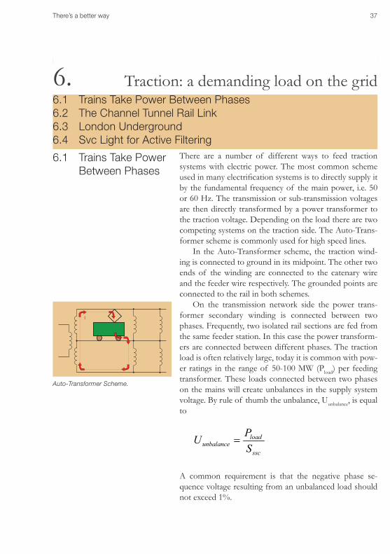
There are a number of different ways to feed traction systems with electric power. The most common scheme used in many electrification systems is to directly supply it by the fundamental frequency of the main power, i.e. 50 or 60 Hz. The transmission or sub-transmission voltages are then directly transformed by a power transformer to the traction voltage. Depending on the load there are two competing systems on the traction side. The Auto-Trans-former scheme is commonly used for high speed lines.
In the Auto-Transformer scheme, the traction wind-ing is connected to ground in its midpoint. The other two ends of the winding are connected to the catenary wire and the feeder wire respectively. The grounded points are connected to the rail in both schemes.
On the transmission network side the power trans-former secondary winding is connected between two phases. Frequently, two isolated rail sections are fed from the same feeder station. In this case the power transform-ers are connected between different phases. The traction load is often relatively large, today it is common with pow-er ratings in the range of 50-100 MW (Pload) per feeding transformer. These loads connected between two phases on the mains will create unbalances in the supply system voltage. By rule of thumb the unbalance, Uunbalance, is equal to
ssc
loadunbalance S
PU =
A common requirement is that the negative phase se-quence voltage resulting from an unbalanced load should not exceed 1%.
II
II
Auto-Transformer Scheme.
38 There’s a better way
Traction: A Demanding Load on the Grid6.
16 2/3 CyclesIn 16 2/3 cycles systems, a conversion system transforms 50/60 Hz. The conversion system loads the three-phase system symmetrically. Therefore restoring and maintaining balance between phases is not an issue. However, keeping catenary voltages high and stable, and limiting harmonic distortion, may still be issues to be taken into consider-ation when designing the system.
For 50 and 60 cycles, X (inductive catenary reactance) dominates over R (catenary resistance). For 16 2/3 cycles, X is diminished and becomes approximately equal to R. This makes voltage control along the catenary less criti-cal. Still, in cases of weak feeding, with feeding points far apart, or with feeding from only one side, trackside, single-phase SVC for 16 2/3 cycles might prove useful, for dy-namic voltage support and harmonic mitigation.
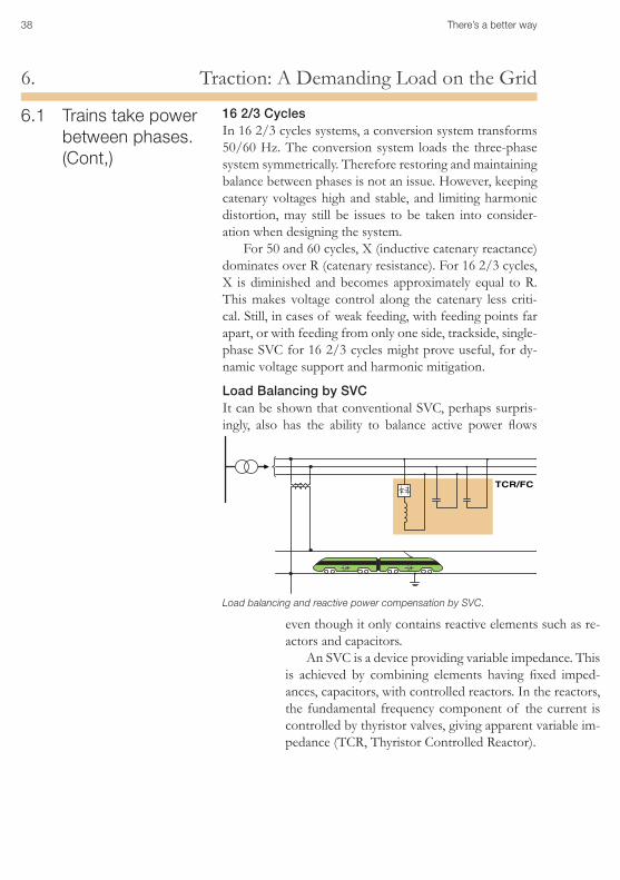
Load Balancing by SVCIt can be shown that conventional SVC, perhaps surpris-ingly, also has the ability to balance active power flows
6.1 Trains take power between phases. (Cont,)
Load balancing and reactive power compensation by SVC.
even though it only contains reactive elements such as re-actors and capacitors.
An SVC is a device providing variable impedance. This is achieved by combining elements having fixed imped-ances, capacitors, with controlled reactors. In the reactors, the fundamental frequency component of the current is controlled by thyristor valves, giving apparent variable im-pedance (TCR, Thyristor Controlled Reactor).
There’s a better way 39
Traction: A Demanding Load on the Grid6.
Benefits From Utilizing FACTS in Rail TractionBy means of FACTS the following important benefits can be brought about for power grids feeding railway systems, as well as for rail traction loads themselves:
Dynamic balancing of non-symmetrical loads fed between •two phases of three-phase grids;
Dynamic mitigation of voltage fluctuations in feeding grids •caused by heavy fluctuations of railway loads;
Mitigation of harmonics injected into supply grids from •traction devices;
Power factor correction at the point of common coupling, •with a high and stable power factor at all times, regardless of load changes and fluctuations;
Dynamic voltage support of catenaries feeding high •power locomotives, thereby maintaining traction capability despite weak feeding, without harmful voltage drops along the catenary;
Dynamic voltage support of catenaries during outages of •feeding points, thereby enabling adequate power infeed into locomotives, or, alternatively, with fewer infeed points required in the system;
Dynamic voltage control and harmonic mitigation of AC •supply systems for DC converter fed traction (typically underground and suburban trains).
In all these cases, time as well as money can be saved by not having to invest in costly and time- consuming reinforcement of the railway feeding infrastructure such as building new transmission or sub-transmission lines, new power generation, and/or building new substations and infeed points.
6.1 Trains Take Power Between Phases. (Cont,)
40 There’s a better way
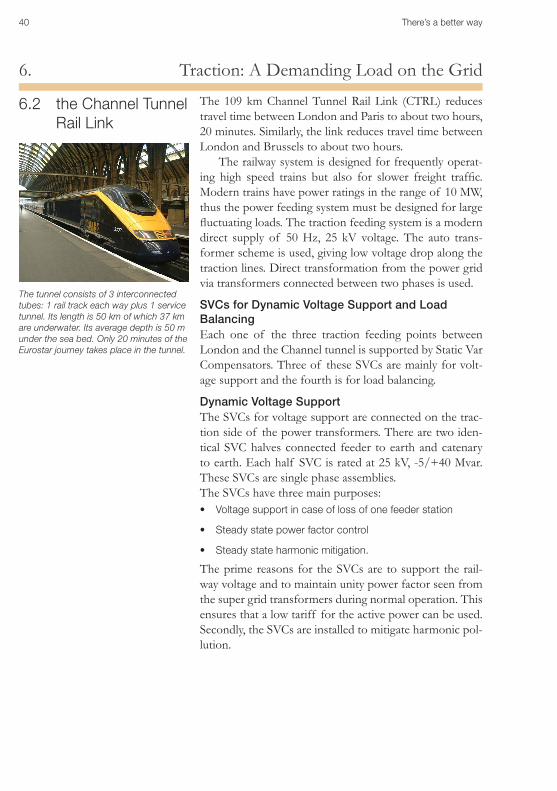
Traction: A Demanding Load on the Grid6.The 109 km Channel Tunnel Rail Link (CTRL) reduces travel time between London and Paris to about two hours, 20 minutes. Similarly, the link reduces travel time between London and Brussels to about two hours.
The railway system is designed for frequently operat-ing high speed trains but also for slower freight traffic. Modern trains have power ratings in the range of 10 MW, thus the power feeding system must be designed for large fluctuating loads. The traction feeding system is a modern direct supply of 50 Hz, 25 kV voltage. The auto trans-former scheme is used, giving low voltage drop along the traction lines. Direct transformation from the power grid via transformers connected between two phases is used.
SVCs for Dynamic Voltage Support and Load BalancingEach one of the three traction feeding points between London and the Channel tunnel is supported by Static Var Compensators. Three of these SVCs are mainly for volt-age support and the fourth is for load balancing.
Dynamic Voltage SupportThe SVCs for voltage support are connected on the trac-tion side of the power transformers. There are two iden-tical SVC halves connected feeder to earth and catenary to earth. Each half SVC is rated at 25 kV, -5/+40 Mvar. These SVCs are single phase assemblies. The SVCs have three main purposes:
Voltage support in case of loss of one feeder station•
Steady state power factor control•
Steady state harmonic mitigation.•
The prime reasons for the SVCs are to support the rail-way voltage and to maintain unity power factor seen from the super grid transformers during normal operation. This ensures that a low tariff for the active power can be used. Secondly, the SVCs are installed to mitigate harmonic pol-lution.
6.2 the Channel Tunnel Rail Link
The tunnel consists of 3 interconnected tubes: 1 rail track each way plus 1 service tunnel. Its length is 50 km of which 37 km are underwater. Its average depth is 50 m under the sea bed. Only 20 minutes of the Eurostar journey takes place in the tunnel.
There’s a better way 41
Traction: A Demanding Load on the Grid6.
6.2 The Channel Tun-nel Rail Link (Cont.)
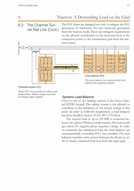
The SVC filters are designed not only to mitigate the SVC generation of harmonics but also harmonic generation from the traction loads. There are stringent requirements on the allowed contribution to the harmonic level at the connection points to the transmission grid from the trac-tion system.
Load balancer SVC
This must balance the unsymmetrical load towards the supplying network
Trackside booster SVC
These SVC must provide the railway with single phase, reliable voltage even with one feeder station tripped Dynamic Load Balancer
Close to one of the feeding stations is the Cross Chan-nel HVDC located. The railway system is not allowed to contribute to the unbalance of the system voltage at this point. In order to fulfil this requirement, a load balancer has been installed, rated at 33 kV, -80/+170 Mvar.
The traction load of up to 120 MW is connected be-tween two phases. Without compensation, this load would give about 2% negative phase sequence voltage. In order to counteract the unbalanced load, the load balancer (an unsymmetrically controlled SVC) was installed. The load balancer transfers active power between the phases in or-der to create a balanced load seen from the super grid.
42 There’s a better way
Traction: A Demanding Load on the Grid6.
6.3 London Under-ground
The 22 kV and 11 kV electrical distribution system pro-vides power to the London Underground Ltd. (LUL) net-work. LUL has closed down its old gas/oil fired power plants as part of a programme for switching over to tak-ing its power from the London public grid. As the Under-ground load consists to a great extent of diode convert-ers, special measures have had to be taken to ensure that distortion such as voltage fluctuations and harmonics does not reach out into the public grid to become a nuisance to other subscribers connected to the same grid.
Svcs for Dynamic Voltage Support and Harmonic FilteringExtensive system studies have been undertaken to map sources of distortion and identify proper measures to be taken. As a result, a total of six Static Var Compensators (SVC) and ten Harmonic Filters have been specified and installed in critical points of the LUL 22 kV and 11 kV distribution grid.
Due to the scarceness of space and vicinity to under-ground stations, special measures had to be taken to lay out the hardware in a compact way as well as ensure adequate confinement of noise and magnetic fields. Thus, iron core reactors were utilized for the TCR, which offered a more compact physical design than air core reactors. Likewise, due to the close vicinity of the SVCs to populated parts of the Metropolitan area, magnetic clearance becomes an issue of importance. In this respect, iron core reactors are superiour to air core reactors, as well. The magnetic field is required not to exceed 1.6 mT at the boundary of any of the SVCs. Measurements have confirmed that this re-quirement is indeed fulfilled.
With the SVCs in operation, voltage fluctuations at the points of common connection to the public grid are con-fined to a specified maximum of 1%.
There’s a better way 43
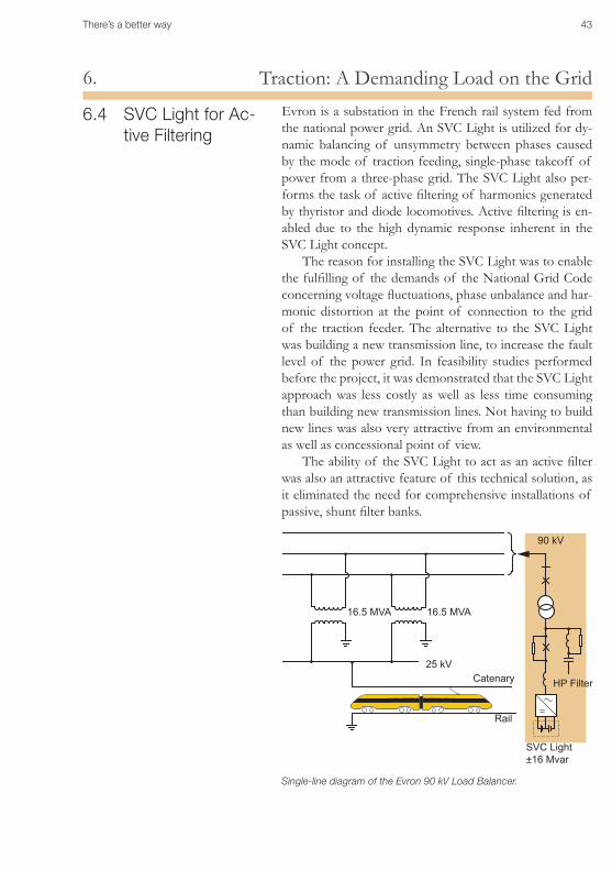
Traction: A Demanding Load on the Grid6.Evron is a substation in the French rail system fed from the national power grid. An SVC Light is utilized for dy-namic balancing of unsymmetry between phases caused by the mode of traction feeding, single-phase takeoff of power from a three-phase grid. The SVC Light also per-forms the task of active filtering of harmonics generated by thyristor and diode locomotives. Active filtering is en-abled due to the high dynamic response inherent in the SVC Light concept.
The reason for installing the SVC Light was to enable the fulfilling of the demands of the National Grid Code concerning voltage fluctuations, phase unbalance and har-monic distortion at the point of connection to the grid of the traction feeder. The alternative to the SVC Light was building a new transmission line, to increase the fault level of the power grid. In feasibility studies performed before the project, it was demonstrated that the SVC Light approach was less costly as well as less time consuming than building new transmission lines. Not having to build new lines was also very attractive from an environmental as well as concessional point of view.
The ability of the SVC Light to act as an active filter was also an attractive feature of this technical solution, as it eliminated the need for comprehensive installations of passive, shunt filter banks.
Single-line diagram of the Evron 90 kV Load Balancer.
90 kV
HP Filter
16.5 MVA 16.5 MVA
25 kVCatenary
Rail
SVC Light ±16 Mvar
6.4 SVC Light for Ac-tive Filtering
44 There’s a better way
Traction: A Demanding Load on the Grid6.The Load Balancer is rated at 90 kV, 16 MVA. It is rated to accommodate a single-phase active load size of ≤ 17 MW. Its task is to confine the grid unbalance at 90 kV as follows:
≤• ≤1%forSSC≥600MVA(normalnetworkconditions);
≤• 1.5% for 300 MVA ≤ SSC ≤ 600 MVA (abnormal (N-1) network conditions).
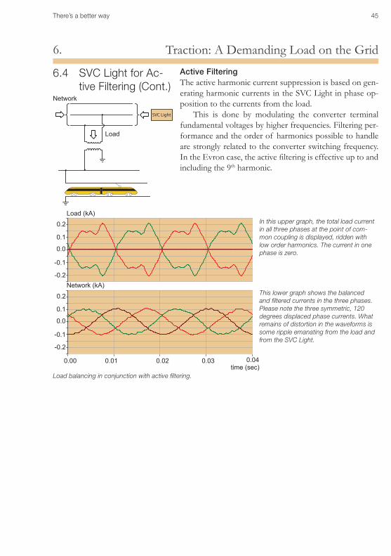
Load BalancingMeasurements performed since the installation of the SVC Light have shown a distinct improvement of voltage unbalance. With the SVC Light in operation, the voltage unbalance does not exceed 1%.
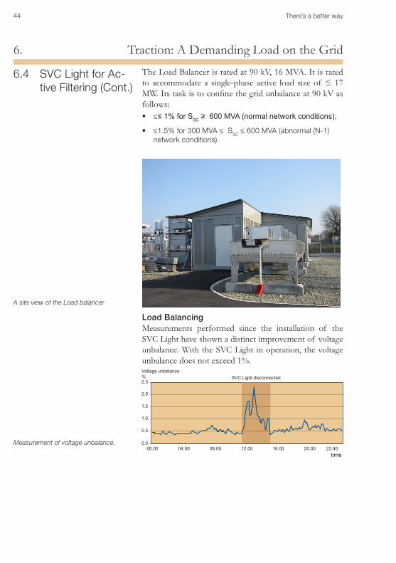
A site view of the Load balancer
Measurement of voltage unbalance.
2.5
2.0
1.5
1.0
0.5
0.000.00 04.00 08.00 12.00 16.00 20.00 22.40
SVC Light disconnectedVoltage unbalance%
6.4 SVC Light for Ac-tive Filtering (Cont.)
time
There’s a better way 45
Traction: A Demanding Load on the Grid6.
Active FilteringThe active harmonic current suppression is based on gen-erating harmonic currents in the SVC Light in phase op-position to the currents from the load.
This is done by modulating the converter terminal fundamental voltages by higher frequencies. Filtering per-formance and the order of harmonics possible to handle are strongly related to the converter switching frequency. In the Evron case, the active filtering is effective up to and including the 9th harmonic.
6.4 SVC Light for Ac-tive Filtering (Cont.)
Load (kA)
Load
Network (kA)
Network
0.01 0.020.00 0.03 0.04time (sec)
0.1
0.1
0.2
0.2
-0.2
-0.2
-0.1
-0.1
0.0
0.0
In this upper graph, the total load current in all three phases at the point of com-mon coupling is displayed, ridden with low order harmonics. The current in one phase is zero.
SVC Light
This lower graph shows the balanced and filtered currents in the three phases. Please note the three symmetric, 120 degrees displaced phase currents. What remains of distortion in the waveforms is some ripple emanating from the load and from the SVC Light.
Load balancing in conjunction with active filtering.
46 There’s a better way
Grid Integration of Wind Farms7.
7.1 Wind Farms
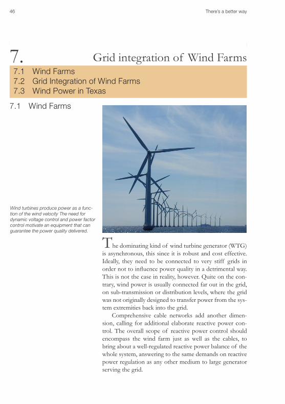
The dominating kind of wind turbine generator (WTG) is asynchronous, this since it is robust and cost effective. Ideally, they need to be connected to very stiff grids in order not to influence power quality in a detrimental way. This is not the case in reality, however. Quite on the con-trary, wind power is usually connected far out in the grid, on sub-transmission or distribution levels, where the grid was not originally designed to transfer power from the sys-tem extremities back into the grid.
Comprehensive cable networks add another dimen-sion, calling for additional elaborate reactive power con-trol. The overall scope of reactive power control should encompass the wind farm just as well as the cables, to bring about a well-regulated reactive power balance of the whole system, answering to the same demands on reactive power regulation as any other medium to large generator serving the grid.
Grid integration of Wind Farms7.1 Wind Farms7.2 Grid Integration of Wind Farms7.3 Wind Power in Texas
7.
Wind turbines produce power as a func-tion of the wind velocity The need for dynamic voltage control and power factor control motivate an equipment that can guarantee the power quality delivered.
There’s a better way 47
Grid Integration of Wind Farms7.
7.2 Grid Integration of Wind Farms
G
G
G
G
G
G
GSVC
Grid
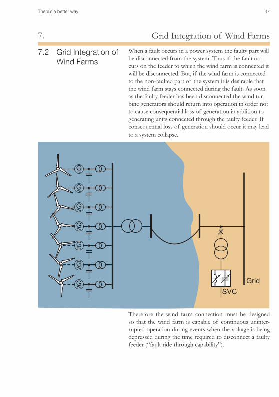
When a fault occurs in a power system the faulty part will be disconnected from the system. Thus if the fault oc-curs on the feeder to which the wind farm is connected it will be disconnected. But, if the wind farm is connected to the non-faulted part of the system it is desirable that the wind farm stays connected during the fault. As soon as the faulty feeder has been disconnected the wind tur-bine generators should return into operation in order not to cause consequential loss of generation in addition to generating units connected through the faulty feeder. If consequential loss of generation should occur it may lead to a system collapse.
Therefore the wind farm connection must be designed so that the wind farm is capable of continuous uninter-rupted operation during events when the voltage is being depressed during the time required to disconnect a faulty feeder (“fault ride-through capability”).
48 There’s a better way
Grid Integration of Wind Farms7.When the electrical network is weak the behaviour of the wind farm at network faults will be strongly improved by reactive power support at the grid connection point. An SVC can be provided as a reactive power source located close to the farm. This approach has a number of advan-tages:
Full compensation of wind farm and cable in one system•
Fulfilling the national Grid Code•
Control of reactive power, even without the wind farm in •operation
Lower wind farm complexity•
High wind farm availability•
Improvement of dynamic voltage stability in the grid•
Wind farm plus cable plus SVC act together to offer MW •and MVAr in the grid, just like any other major source of generation.
7.2 Grid Integration of Wind Farms. (Cont.)
There’s a better way 49
Grid Integration of Wind Farms7.
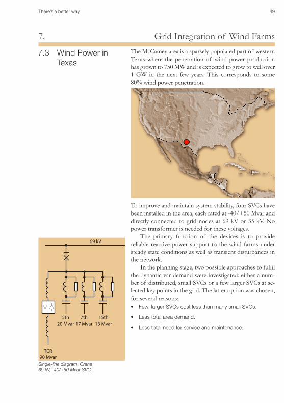
7.3 Wind Power in Texas
The McCamey area is a sparsely populated part of western Texas where the penetration of wind power production has grown to 750 MW and is expected to grow to well over 1 GW in the next few years. This corresponds to some 80% wind power penetration.
To improve and maintain system stability, four SVCs have been installed in the area, each rated at -40/+50 Mvar and directly connected to grid nodes at 69 kV or 35 kV. No power transformer is needed for these voltages.
The primary function of the devices is to provide reliable reactive power support to the wind farms under steady state conditions as well as transient disturbances in the network.
In the planning stage, two possible approaches to fulfil the dynamic var demand were investigated: either a num-ber of distributed, small SVCs or a few larger SVCs at se-lected key points in the grid. The latter option was chosen, for several reasons:
Few, larger SVCs cost less than many small SVCs. •
Less total area demand.•
Less total need for service and maintenance.•
69 kV
5th20 Mvar
7th17 Mvar
15th13 Mvar
TCR90 Mvar
Single-line diagram, Crane 69 kV, -40/+50 Mvar SVC.
50 There’s a better way
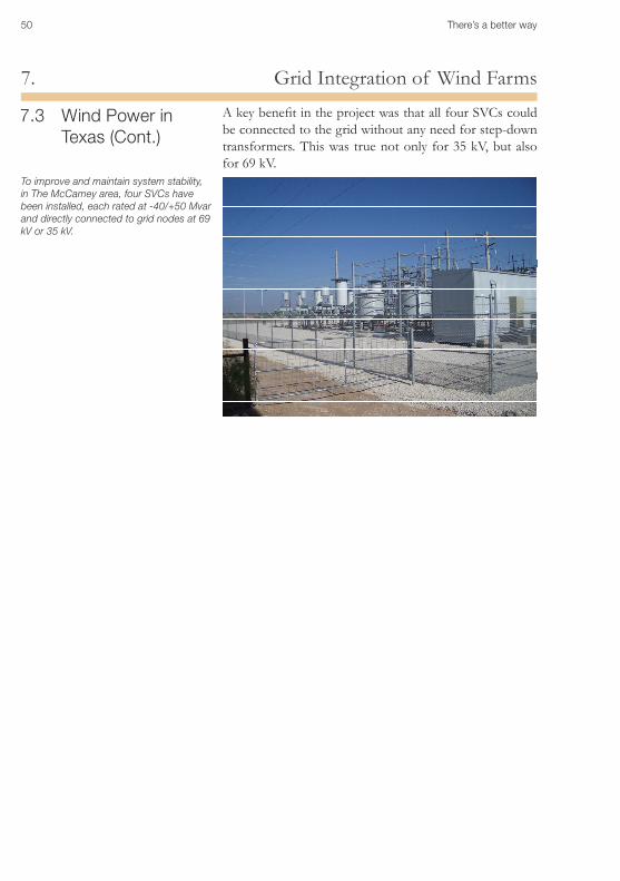
Grid Integration of Wind Farms7.A key benefit in the project was that all four SVCs could be connected to the grid without any need for step-down transformers. This was true not only for 35 kV, but also for 69 kV.
7.3 Wind Power in Texas (Cont.)
To improve and maintain system stability, in The McCamey area, four SVCs have been installed, each rated at -40/+50 Mvar and directly connected to grid nodes at 69 kV or 35 kV.
There’s a better way 51
Static Var Compensation, SVC8.
Static Var Compensation, SVC8.1 Introduction8.2 A Boiling Ocean Becomes a Mere Ripple8.3 Thyristor-Switched Capacitors TSC8.4 Thyristor-Controlled Reactor TCR8.5 Reactors and Capacitors Working Together
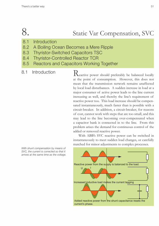
8.1 Introduction Reactive power should preferably be balanced locally at the point of consumption. However, this does not mean that the transmission network remains unaffected by local load disturbances. A sudden increase in load at a major consumer of active power leads to the line current increasing as well, and thereby the line’s requirement of reactive power too. This load increase should be compen-sated instantaneously, much faster than is possible with a circuit-breaker. In addition, a circuit-breaker, for reasons of cost, cannot work with steps that are too small, and this may lead to the line becoming over-compensated when a capacitor bank is connected in to the line. From this problem arises the demand for continuous control of the added or removed reactive power.
With ABB’s SVC reactive power can be switched in instantaneously to meet sudden load changes, or carefully matched for minor adjustments to complex processes.
8.
With shunt compensation by means of SVC, the current is corrected so that it arrives at the same time as the voltage.
U I
Increased inductive load makes the current lagging
Added reactive power from the shunt capacitance resets the current’s phase.
Reactive power from the supply is balanced to the load.
52 There’s a better way
Static Var Compensation, SVC8.
8.2 A Boiling Ocean Becomes a Mere Ripple
Svc Fast But “Gentle”In extensive line networks there are points where produc-ers and consumers of electric power meet. At such Points of Common Coupling (PCC) the risk of disturbances is very great. For example, a rolling mill starts up, the supply line is interrupted due to a lightning strike, an arc furnace is fired, etc.
SVC is fast enough to compensate the exposed lines with so much reactive power that the voltage changes are reduced to a mere “ripple”.
In SVC we have acquired a means of control that can add exactly as much reactive power as is necessary and it can furthermore be applied “gently”.
SVC technology is based on fast switches that are not built up of mechanical moving parts, but of semiconduc-tors. A semiconductor is a material that in certain circum-stances conducts electric current and in others serves as an insulator.
In a few millionths of a second the thyristor can change over from being an insulator to being a conductor.
It is so fast that it can cut away a small part of the alter-nating current’s half-waves, so that the amount of current that passes through the thyristor during a certain period is reduced.
Building Blocks for SVCSVC is a concept consisting of various building blocks that can either be used individually or in more or less complex combinations. In this manner a great deal can be achieved; everything from a simple on/off switching capacitor to steplessly controlled systems with very sophisticated con-trol features in order both to provide and absorb reactive power.
We have already noted that capacitors are used to add reactive power to a network.
Through an electric pulse the thyristor can change over from insulator to conductor in a few millionths of a second. It is so fast that it can cut away part of the alternating current’s half-waves so that the amount of current passing through the thyristor during a certain period is reduced.
There’s a better way 53
Static Var Compensation, SVC8.
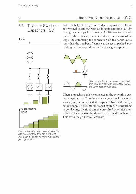
8.3 Thyristor-Swiched Capacitors TSC
TSC
By combining the connection of capacitor banks, more steps than the number of banks can be achieved. Here three banks give eight steps.
With the help of a thyristor bridge a capacitor bank can be switched in and out with an insignificant time-lag. By having several capacitor banks with different reactive ca-pacities, the reactive power added can be controlled in steps. By combining the connection of the banks, more steps than the number of banks can be accomplished; two banks give four steps, three banks give eight steps, etc.
To get smooth current inception, the thyris-tors are only fired when the voltage across the valve goes through zero.
Added reactive power
When a capacitor bank is connected to the network, a cur-rent surge occurs. To reduce this surge, a small reactor is always placed in series with the capacitor bank and the thy-ristor bridge. To get smooth transit from non-conducting to conducting, the thyristors are only fired when the alter-nating voltage across the thyristors passes through zero. This saves the grid from transients.
54 There’s a better way
Static Var Compensation, SVC8.
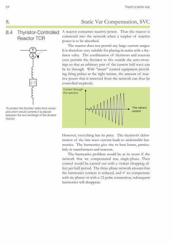
8.4 Thyristor-Controlled Reactor TCR
A reactor consumes reactive power. Thus the reactor is connected into the network when a surplus of reactive power is to be absorbed.
The reactor does not permit any large current surges. It is therefore very suitable for placing in series with a thy-ristor valve. The combination of thyristors and reactors even permits the thyristor to fire outside the zero-cross-ings so that an arbitrary part of the current half-wave can be let through. With “smart” control equipment provid-ing firing pulses at the right instant, the amount of reac-tive power that is removed from the network can thus be controlled steplessly.
However, everything has its price. The thyristor’s defor-mation of the sine wave current leads to undesirable har-monics. The harmonics give rise to heat losses, particu-larly in transformers and reactors.
The harmonics problem would be at its worst if the network that we compensated was single-phase. Then control would be carried out with a violent chopping ef-fect per half-period. The three-phase network ensures that the harmonics content is reduced, and if we compensate with six phases or with a 12-pulse connection, subsequent harmonics will disappear.
To protect the thyristor valve from exces-sive short circuit currents it is placed between the two windings of the divided reactor.
The valve’s control
Current through the reactors
There’s a better way 55
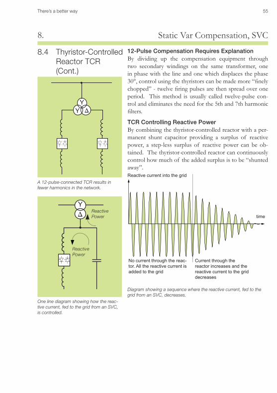
Static Var Compensation, SVC8.
12-Pulse Compensation Requires ExplanationBy dividing up the compensation equipment through two secondary windings on the same transformer, one in phase with the line and one which displaces the phase 30°, control using the thyristors can be made more “finely chopped” - twelve firing pulses are then spread over one period. This method is usually called twelve-pulse con-trol and eliminates the need for the 5th and 7th harmonic filters.
TCR Controlling Reactive PowerBy combining the thyristor-controlled reactor with a per-manent shunt capacitor providing a surplus of reactive power, a step-less surplus of reactive power can be ob-tained. The thyristor-controlled reactor can continuously control how much of the added surplus is to be “shunted away”.
8.4 Thyristor-Controlled Reactor TCR (Cont.)
Diagram showing a sequence where the reactive current, fed to the grid from an SVC, decreases.
A 12-pulse-connected TCR results in fewer harmonics in the network.
Reactive Power
No current through the reac-tor. All the reactive current is added to the grid
Current through the reactor increases and the reactive current to the grid decreases
time
Reactive current into the grid
One line diagram showing how the reac-tive current, fed to the grid from an SVC, is controlled.
Reactive Power
56 There’s a better way
Static Var Compensation, SVC8.
+ =
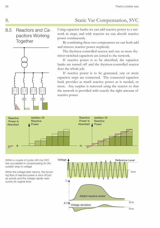
8.5 Reactors and Ca-pacitors Working Together
Using capacitor banks we can add reactive power to a net-work in steps, and with reactors we can absorb reactive power continuously.
By combining these two components we can both add and remove reactive power steplessly.
The thyristor-controlled reactor and one or more thy-ristor-switched capacitors are joined to the network.
If reactive power is to be absorbed, the capacitor banks are turned off and the thyristor-controlled reactor does the whole job.
If reactive power is to be generated, one or more capacitor steps are connected. The connected capacitor bank provides as much reactive power as is needed, or more. Any surplus is removed using the reactor so that the network is provided with exactly the right amount of reactive power.
Within a couple of cycles (40 ms) SVC has succeeded in compensating for the sudden drop in voltage.
When the voltage later returns, the incom-ing flow of reactive power is shut off just as quickly and the voltage rapidly reas-sumes its original level.
Addition Of Reactive Power
Addition Of Reactive Power
Reactive Power Is
Absorbed
Reactive Power Is
Absorbed
Voltage deviation
Reference LevelVoltage
Added reactive power
+ =
Q
ΔV
time
time
time
There’s a better way 57
STATCOM and SVC Light®9.
STATCOM and SVC Light®
9.1 General9.2 Technology and Principle9.3 Statcom in Back-To-Back Configuration
9.
Electrical loads both generate and absorb reactive pow-er. Since the load often varies considerably from one hour to another, the reactive power balance in a grid varies as well. The result can be unacceptable voltage variations, a voltage depression, or even a voltage collapse. Similarly to the SVC the STATCOM can provide in-stantaneous and continuously variable reactive power in response to grid voltage fluctuations, enhancing the grid voltage stability.
Its performance can be dedicated to active harmonic filtering and voltage flicker mitigation.
9.1 General
The flicker emanating from an electric arc furnace actually disappears in the back-ground noise, thanks to the STATCOM, the EAF has been made invisible from the elec-trical grid´s point of view. Field registration.0
0.5
1
1.5
Pst STATCOM disconnected
STATCOM can be comparatively compact, its footprint is normally small compared with a standard SVC and its harmonics filters. ABB has branded this high performance STATCOM concept SVC Light®.
Installing a STATCOM at one or more suitable points in the network will increase the grid transfer capability through enhanced voltage stability, while maintaining a smooth voltage profile under different network conditions. The STATCOM provides additional versatility in terms of power quality improvement capabilities.
Active FilteringSVC Light can generate harmonic currents in phase op-position to the currents from the load. This is done by modulating the converter terminal voltages by higher fre-quencies. In the Evron case (page 44), the active filtering is effective up to and including the 9th harmonic.
Load
Network
Active filtering and load balancing by means of SVC Light®. For detailed information on the Evron installation see page 44. Field registration.
58 There’s a better way
STATCOM and SVC Light®9.
9.2 Technology and Principle
The STATCOM operates according to the voltage source converter principle (VSC), which together with PWM (Pulsed Width Modulation) switching of IGBTs (Insulated Gate Bipolar Transistors) gives it unequalled performance in terms of effective rating and response speed.
- Ud
+Ud
IU
SVC Light can be seen as a voltage source behind a reac-tance. Physically it is built as a three-level inverter operat-ing on a constant DC-voltage. It provides reactive power generation as well as absorption purely by means of elec-tronic processing of voltage and current waveforms in a voltage source converter (the grid will see it as a synchro-nous machine without inertia). This means that capacitor banks and shunt reactors are not needed for generation and absorption of reactive power, facilitating a compact design, a small footprint.
The high switching frequency of IGBT allows ex-tremely fast control, which can be used in areas such as mitigation of voltage flicker caused by electric arc furnac-es, voltage balancing, harmonic filtering and robust grid voltage recovery support. A DC capacitor bank is utilized to support and stabilize the controlled DC voltage needed for the converter operation.
The high switching frequency of IGBT allows extremely fast control. By means of high frequency switching it can even con-trol the shape of the voltage sine-curve.
A DC capacitor bank is utilized as DC voltage source.
There’s a better way 59
STATCOM and SVC Light®9.
9.3 STATCOM in Back-To-Back Configuration
Voltage Source Converters (VSC) connected in “back-to-back configuration” between two AC busbars have the ca-pability to operate with active power allowing a dual pur-pose scheme to be feasible.
This Back-to-Back arrangement is useful for connecting two networks asynchronously with full control of voltage, frequency and phase angle.
This Back-to-Back Light can even support the feeding and receiving network with reactive power and the receiv-ing network with active power simultaneously.
G G
Comparison: Classic SVC and STATCOMClassic SVC
Classic SVC
STATCOM
STATCOM
Controlled inductor
Switched capacitors
Voltage Source Converter
IloadIload
IcompIcomp
load load
R
L
R
L
Q ~ U• 2 Load balancing•Voltage control•POD•
Q ~ U •Voltage control•Load balancing•Fast control•Activefiltering•Flicker mitigation•Low content of •harmonicsSmaller footprint•
UAC
IINDICAP
Vmax
VN
Vmin
For equivalent performance at Vmin the classic SVC will be larger in nominal rating
STATCOM delivers the maximum compensa-tion current indepen-dently of the voltage.
60 There’s a better way
Series Compensation, SC, and TCSC10.
Series Compensation, SC, and TCSC10.10.1 Introduction 10.2 Increased Capacity and Improved Voltage Stability 10.3 Increased Capacity and Maintained Angular Stability 10.4 Increased Capacity and Optimized Power Sharing Between
Parallel Circuits10.5 Over Voltage Protection of SC Banks10.6 Controllable Series Compensation, TCSC
10.1 Introduction Fixed Series Compensation is since long the preferred solution when vast bulk transmission corridors are to be optimized. Inserting a capacitive reactance in series with a long (typically more than 200km) transmission line, re-duces both the angular deviation between supplying gen-erators and the receiving and the voltage drop. The result is increased loadability and stability.
The fact that it is the current through the transmission line that directly ”drives” the Mvar output from the capacitor, makes the compensation concept ”self regulating”. This straightforward principle assures that Series Compensa-tion is an extremely cost effective solution.
G1 G2
G1 G2
C
G1
G1
C
δ2C
δ2
δ1
δ1
δ=0
P
P
PC
Increased Stabillity
Inserting a capacitive reactance in series with a long (typically more than 200km) transmission line reduces the angular deviation between supplying generators and the receiving.
Increased Capacity
Inserting a capacitive reactance in series with a long (typically more than 200km) transmission line, reduces the impedance and increases therefore the amount of power that can be transferred.
There’s a better way 61
Series Compensation, SC, and TCSC10.
10.1 Introduction (Cont.) Squeezing more power out of existing lines can eliminate the need to build new lines which all adds up to reduced environmental impact and significant cost and time sav-ings. Series compensation provides:
Increased transmission capacity•
Increased voltage stability of the grid •
Increased transient (angular) stability of a power corridor•
Damping of the first swing•
Optimized power sharing between parallel circuits •
Series Compensation scheme involving Thyristor Control allows for rapid dynamic modulation of the inserted re-actance. At interconnecting points between transmission grids, this can provide strong damping torque on inter-area electromechanical oscillations. Therefore a TCSC rated at some 100 Mvar can make it possible to interconnect grids housing many thousands of MW´s of generating capacity. Often the TCSC is here combined with fixed series com-pensation in order to increase the transient stability in the most cost effective way.
The TCSC concept can provide inherent immunity against Subsynchronous Resonance (SSR), and thus allows for extended use of series capacitor in specific transmis-sion grids comprising thermal generation.
Series compensation can by means of TCSC allso pro-vide:
Damping of active power oscillations •
Post-contingency stability improvements •
Dynamic power flow control •
Mitigation of any possible sub-syncronous resonance •
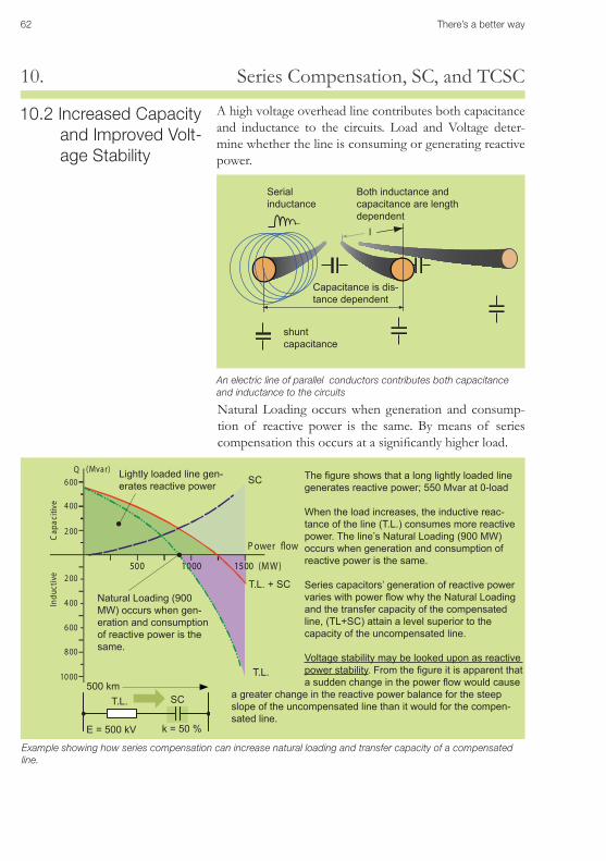
62 There’s a better way
Series Compensation, SC, and TCSC10.
10.2 Increased Capacity and Improved Volt-age Stability
A high voltage overhead line contributes both capacitance and inductance to the circuits. Load and Voltage deter-mine whether the line is consuming or generating reactive power.
Cap
aciti
veIn
duct
ive 200
400
600
800
1000
200
400
600Q (Mvar)
500 1000 1500
P ower �ow
(MW)
SC
T.L. + SC
T.L.
Example showing how series compensation can increase natural loading and transfer capacity of a compensated line.
Thefigureshowsthatalonglightlyloadedlinegeneratesreactivepower;550Mvarat0-load
When the load increases, the inductive reac-tance of the line (T.L.) consumes more reactive power. The line’s Natural Loading (900 MW) occurs when generation and consumption of reactive power is the same.
Series capacitors’ generation of reactive power varieswithpowerflowwhytheNaturalLoadingand the transfer capacity of the compensated line, (TL+SC) attain a level superior to the capacity of the uncompensated line.
Voltage stability may be looked upon as reactive power stability.Fromthefigureitisapparentthatasuddenchangeinthepowerflowwouldcause
a greater change in the reactive power balance for the steep slope of the uncompensated line than it would for the compen-sated line.
Lightly loaded line gen-erates reactive power
Natural Loading (900 MW) occurs when gen-eration and consumption of reactive power is the same.
shunt capacitance
Serial inductance
An electric line of parallel conductors contributes both capacitance and inductance to the circuits
Capacitance is dis-tance dependent
Both inductance and capacitance are length dependent
l
SC
E=500kV
T.L.
k=50%
500 km
Natural Loading occurs when generation and consump-tion of reactive power is the same. By means of series compensation this occurs at a significantly higher load.
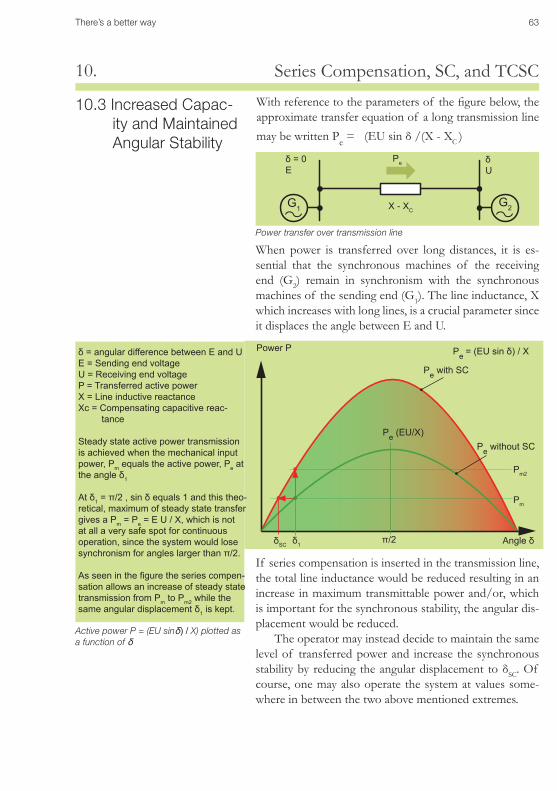
There’s a better way 63
Series Compensation, SC, and TCSC10.
δ=angulardifferencebetweenEandUE=SendingendvoltageU=ReceivingendvoltageP=TransferredactivepowerX=LineinductivereactanceXc=Compensatingcapacitivereac- tance
Steady state active power transmission is achieved when the mechanical input power, Pm equals the active power, Pe at theangleδ1
Atδ1=π/2,sinδequals1andthistheo-retical, maximum of steady state transfer gives a Pm=Pe=EU/X,whichisnotat all a very safe spot for continuous operation, since the system would lose synchronismforangleslargerthanπ/2.
Asseeninthefiguretheseriescompen-sation allows an increase of steady state transmission from Pm to Pm2 while the sameangulardisplacementδ1 is kept.
Active power P = (EU sinδ) / X) plotted as a function of δ
δSC
Pe =(EUsinδ)/X
Pe (EU/X)Pe without SC
Pe with SC
δ1π/2
Pm2
Pm
With reference to the parameters of the figure below, the approximate transfer equation of a long transmission line may be written Pe = (EU sin δ /(X - XC )
Power P
Angle δ
When power is transferred over long distances, it is es-sential that the synchronous machines of the receiving end (G2) remain in synchronism with the synchronous machines of the sending end (G1). The line inductance, X which increases with long lines, is a crucial parameter since it displaces the angle between E and U.
10.3 Increased Capac-ity and Maintained Angular Stability
Power transfer over transmission line
δU
δ=0E
Pe
G1 G2X - XC
If series compensation is inserted in the transmission line, the total line inductance would be reduced resulting in an increase in maximum transmittable power and/or, which is important for the synchronous stability, the angular dis-placement would be reduced.
The operator may instead decide to maintain the same level of transferred power and increase the synchronous stability by reducing the angular displacement to δSC. Of course, one may also operate the system at values some-where in between the two above mentioned extremes.
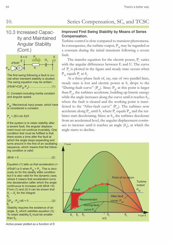
64 There’s a better way
Series Compensation, SC, and TCSC10.
Improved First Swing Stability by Means of Series Compensation.Turbine control is slow compared to transient phenomena. In consequence, the turbine output, PM may be regarded as a constant during the initial transients following a severe fault.
The transfer equation for the electric power, Pe varies with the angular differences between E and U. The curve of Pe is plotted in the figure and steady state occurs when PM equals Pe at δ1
At a three-phase fault of, say, one of two parallel lines, steady state is lost and electric power at δ1 drops to the “During-fault curve” (Pe2). Since PM at this point is larger than Pe2, the turbines accelerate, building up kinetic energy while the angle increases along the curve until it reaches δ2, where the fault is cleared and the working point is trans-ferred to the “After-fault curve” (Pe3). The turbines now accelerate along Pe3 until δ3 where Pe equals PM and the tur-bines start decelerating. Since at δ3, the turbines decelerate from an accelerated level, the angular displacement contin-ues to increase until it reaches an angle (δ4), at which the angle starts to decline.
Thefirstswingfollowingafaultiscru-cial when transient stability is studied.The swing equation may be written: d2δ/dt2=C(PM-Pe)…........................ (1)
C: Constant including inertia constant and angular speed.
PM: Mechanical input power, which here is considered a constant.
Pe=(EUsinδ)/X
If the system is to retain stability after a severe fault, the angular displace-ment must not continue invariably. One conditionthatmustbefulfilledisthatthere exists a time after the fault at which the angle stops expanding and turnsaroundinthefirstofanoscillatingsequence, which means that the follow-ing condition is valid:
dδ/dt=0…………..........................(2)
Equation(1)tellsusthatacceleration(=d2δ/dt2) is 0 when PM=Pe. This is obvi-ously so for the steady state condition but it is also valid for the dynamic case, where it means that acceleration turns into deceleration (after which the angle continuoustoincreaseuntildδ/dt=0).From (1) and (2) it can be shown that δ1→δ4 for the integral
∫(PM - Pe)dδ=0…….....................(3)
Stability requires the existence of an angle,δ4whichsatisfiesequation(3).Toretainstabilityδ4 must be smaller thanδ5.
10.3 Increased Capac-ity and Maintained Angular Stability (Cont.)
δ4
δ1
Power
Angle δ
Fault
Reconnection
Point of no return
Active power plotted as a function of δ .
Turbine output PM
δ1 δ2 δ3 δ4 δ5
π/2
During-fault curve Pe2
After-fault curve, Pe3
G
d2δ/dt2
δ=0 δU-XCE
X
Pe
PM
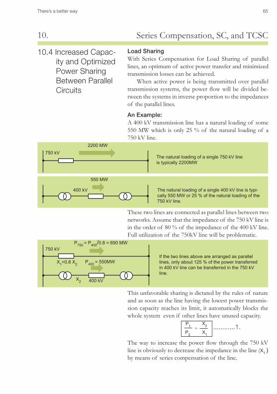
There’s a better way 65
Series Compensation, SC, and TCSC10.
10.4 Increased Capac-ity and Optimized Power Sharing Between Parallel Circuits
Load Sharing With Series Compensation for Load Sharing of parallel lines, an optimum of active power transfer and minimized transmission losses can be achieved.
When active power is being transmitted over parallel transmission systems, the power flow will be divided be-tween the systems in inverse proportion to the impedances of the parallel lines.
An Example: A 400 kV transmission line has a natural loading of some 550 MW which is only 25 % of the natural loading of a 750 kV line.
These two lines are connected as parallel lines between two networks. Assume that the impedance of the 750 kV line is in the order of 80 % of the impedance of the 400 kV line. Full utilization of the 750kV line will be problematic.
750 kV
750 kV
400 kV
400 kV
If the two lines above are arranged as parallel lines,onlyabout125%ofthepowertransferredin 400 kV line can be transferred in the 750 kV line.
The natural loading of a single 750 kV line is typically 2200MW
The natural loading of a single 400 kV line is typi-cally550MWor25%ofthenaturalloadingofthe750 kV line.
P1
P2
X2
X1
=
P400 =550MW
P750 =P400/0.8=690MW
X1=0.8X2
X2
550 MW
2200 MW
This unfavorable sharing is dictated by the rules of nature and as soon as the line having the lowest power transmis-sion capacity reaches its limit, it automatically blocks the whole system even if other lines have unused capacity.
The way to increase the power flow through the 750 kV line is obviously to decrease the impedance in the line (X1 )by means of series compensation of the line.
............1.
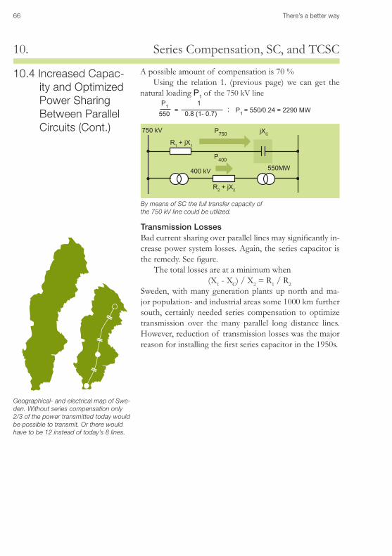
66 There’s a better way
Series Compensation, SC, and TCSC10.
Geographical- and electrical map of Swe-den. Without series compensation only 2/3 of the power transmitted today would be possible to transmit. Or there would have to be 12 instead of today’s 8 lines.
Transmission LossesBad current sharing over parallel lines may significantly in-crease power system losses. Again, the series capacitor is the remedy. See figure.
The total losses are at a minimum when (X1 - XC) / X2 = R1 / R2
Sweden, with many generation plants up north and ma-jor population- and industrial areas some 1000 km further south, certainly needed series compensation to optimize transmission over the many parallel long distance lines. However, reduction of transmission losses was the major reason for installing the first series capacitor in the 1950s.
R1 + jX1
R2 + jX2
jXC
400 kV
750 kV
By means of SC the full transfer capacity of the 750 kV line could be utilized.
P750
P400
A possible amount of compensation is 70 %Using the relation 1. (previous page) we can get the
natural loading P1 of the 750 kV line
10.4 Increased Capac-ity and Optimized Power Sharing Between Parallel Circuits (Cont.)
550MW
P1550
10.8 (1- 0.7)= P1 =550/0.24=2290MW;
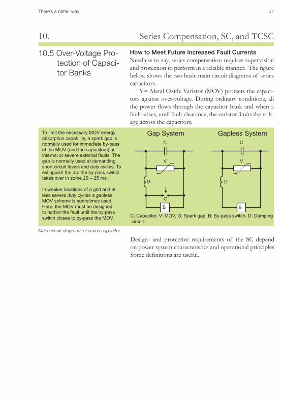
There’s a better way 67
Series Compensation, SC, and TCSC10.
10.5 Over-Voltage Pro-tection of Capaci-tor Banks
How to Meet Future Increased Fault CurrentsNeedless to say, series compensation requires supervision and protection to perform in a reliable manner. The figure below, shows the two basic main circuit diagrams of series capacitors.
V= Metal Oxide Varistor (MOV) protects the capaci-tors against over-voltage. During ordinary conditions, all the power flows through the capacitor bank and when a fault arises, until fault clearance, the varistor limits the volt-age across the capacitors.
Main circuit diagrams of series capacitor.
Design- and protective requirements of the SC depend on power system characteristics and operational principles Some definitions are useful.
To limit the necessary MOV energy absorption capability, a spark gap is normally used for immediate by-pass of the MOV (and the capacitors) at internal or severe external faults. The gap is normally used at demanding short circuit levels and duty cycles. To extinguish the arc the by-pass switch takes over in some 20 – 25 ms.
In weaker locations of a grid and at less severe duty cycles a gapless MOV scheme is sometimes used. Here, the MOV must be designed to harbor the fault until the by-pass switch closes to by-pass the MOV.
G
V
B
D
C C
V
B
D
Gap System Gapless System
C: Capacitor, V: MOV, G: Spark gap, B: By-pass switch, D: Damping circuit
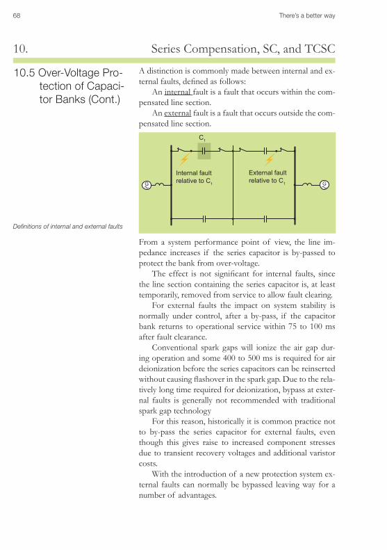
68 There’s a better way
Series Compensation, SC, and TCSC10.
Definitions of internal and external faults
G G
Internal fault relative to C1
External fault relative to C1
From a system performance point of view, the line im-pedance increases if the series capacitor is by-passed to protect the bank from over-voltage.
The effect is not significant for internal faults, since the line section containing the series capacitor is, at least temporarily, removed from service to allow fault clearing.
For external faults the impact on system stability is normally under control, after a by-pass, if the capacitor bank returns to operational service within 75 to 100 ms after fault clearance.
Conventional spark gaps will ionize the air gap dur-ing operation and some 400 to 500 ms is required for air deionization before the series capacitors can be reinserted without causing flashover in the spark gap. Due to the rela-tively long time required for deionization, bypass at exter-nal faults is generally not recommended with traditional spark gap technology
For this reason, historically it is common practice not to by-pass the series capacitor for external faults, even though this gives raise to increased component stresses due to transient recovery voltages and additional varistor costs.
With the introduction of a new protection system ex-ternal faults can normally be bypassed leaving way for a number of advantages.
10.5 Over-Voltage Pro-tection of Capaci-tor Banks (Cont.)
A distinction is commonly made between internal and ex-ternal faults, defined as follows:
An internal fault is a fault that occurs within the com-pensated line section.
An external fault is a fault that occurs outside the com-pensated line section.
C1
C1
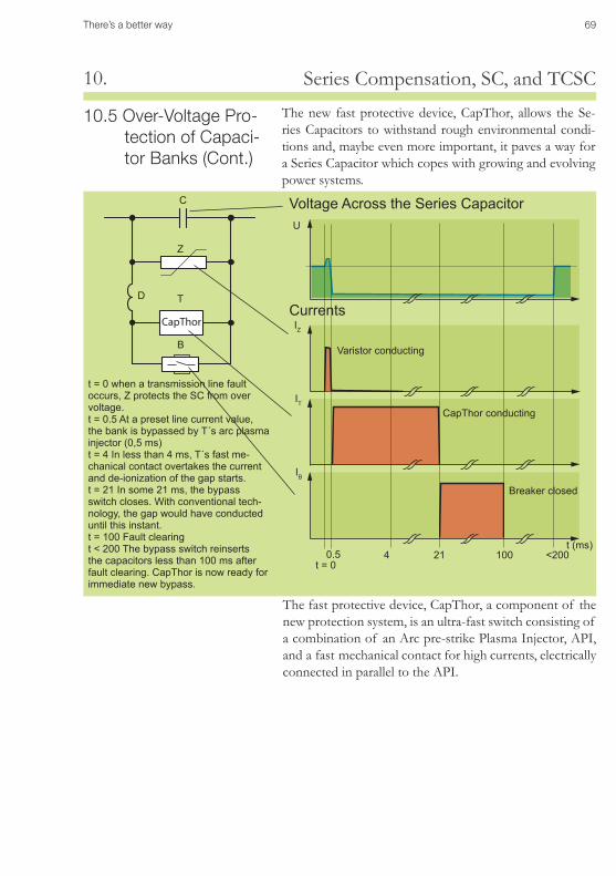
There’s a better way 69
Series Compensation, SC, and TCSC10.
The new fast protective device, CapThor, allows the Se-ries Capacitors to withstand rough environmental condi-tions and, maybe even more important, it paves a way for a Series Capacitor which copes with growing and evolving power systems.
10.5 Over-Voltage Pro-tection of Capaci-tor Banks (Cont.)
The fast protective device, CapThor, a component of the new protection system, is an ultra-fast switch consisting of a combination of an Arc pre-strike Plasma Injector, API, and a fast mechanical contact for high currents, electrically connected in parallel to the API.
t=0whenatransmissionlinefaultoccurs, Z protects the SC from over voltage.t=0.5Atapresetlinecurrentvalue,the bank is bypassed by T´s arc plasma injector (0,5 ms)t=4Inlessthan4ms,T´sfastme-chanical contact overtakes the current and de-ionization of the gap starts.t=21Insome21ms,thebypassswitch closes. With conventional tech-nology, the gap would have conducted until this instant.t=100Faultclearingt < 200 The bypass switch reinserts the capacitors less than 100 ms after fault clearing. CapThor is now ready for immediate new bypass.
CapThor
IT
IB
Z
IZ
U
C
T
B
D
0.5 4 21 100 <200t (ms)
Voltage Across the Series Capacitor
Currents
Varistor conducting
CapThor conducting
Breaker closed
t=0
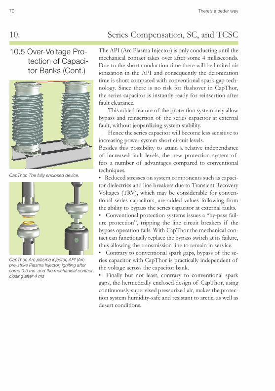
70 There’s a better way
Series Compensation, SC, and TCSC10.
CapThor. The fully enclosed device.
CapThor. Arc plasma injector, API (Arc pre-strike Plasma Injector) igniting after some 0.5 ms and the mechanical contact closing after 4 ms
10.5 Over-Voltage Pro-tection of Capaci-tor Banks (Cont.)
The API (Arc Plasma Injector) is only conducting until the mechanical contact takes over after some 4 milliseconds. Due to the short conduction time there will be limited air ionization in the API and consequently the deionization time is short compared with conventional spark gap tech-nology. Since there is no risk for flashover in CapThor, the series capacitor is instantly ready for reinsertion after fault clearance.
This added feature of the protection system may allow bypass and reinsertion of the series capacitor at external fault, without jeopardizing system stability.
Hence the series capacitor will become less sensitive to increasing power system short circuit levels.Besides this possibility to attain a relative independance of increased fault levels, the new protection system of-fers a number of advantages compared to conventional techniques.• Reduced stresses on system components such as capaci-tor dielectrics and line breakers due to Transient Recovery Voltages (TRV), which may be considerable for conven-tional series capacitors, are added values following from the ability to bypass the series capacitor at external faults.• Conventional protection systems issues a “by-pass fail-ure protection”, tripping the line circuit breakers if the bypass operation fails. With CapThor the mechanical con-tact can functionally replace the bypass switch at its failure, thus allowing the transmission line to remain in service.• Contrary to conventional spark gaps, bypass of the se-ries capacitor with CapThor is practically independent of the voltage across the capacitor bank.• Finally but not least, contrary to conventional spark gaps, the hermetically enclosed design of CapThor, using continuously supervised pressurized air, makes the protec-tion system humidity-safe and resistant to arctic, as well as desert conditions.
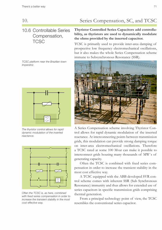
There’s a better way 71
Series Compensation, SC, and TCSC10.
Thyristor Controlled Series Capacitors add controlla-bility, as thyristors are used to dynamically modulate the ohms provided by the inserted capacitor. TCSC is primarily used to provide inter-area damping of prospective low frequency electromechanical oscillations, but it also makes the whole Series Compensation scheme immune to Subsynchronous Resonance (SSR).
10.6 Controllable Series Compensation, TCSC
A Series Compensation scheme involving Thyristor Con-trol allows for rapid dynamic modulation of the inserted reactance. At interconnecting points between transmission grids, this modulation can provide strong damping torque on inter-area electromechanical oscillations. Therefore a TCSC rated at some 100 Mvar can make it possible to interconnect grids housing many thousands of MW´s of generating capacity.
Often the TCSC is combined with fixed series com-pensation in order to increase the transient stability in the most cost effective way.
A TCSC equipped with the ABB developed SVR con-trol scheme comes with inherent SSR (Sub Synchronous Resonance) immunity and thus allows for extended use of series capacitors in specific transmission grids comprising thermal generation.
From a principal technology point of view, the TCSC resembles the conventional series capacitor.
The thyristor control allows for rapid dynamic modulation of the inserted reactance.
Often the TCSC is, as here, combined with fixed series compensation in order to increase the transient stability in the most cost effective way.
TCSC platform near the Brazilian town Imperatriz.
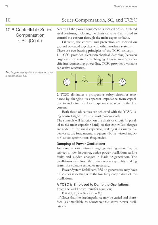
72 There’s a better way
Series Compensation, SC, and TCSC10.
G G
Nearly all the power equipment is located on an insulated steel platform, including the thyristor valve that is used to control the current through the main capacitor bank.
Likewise, the control and protection are located on ground potential together with other auxiliary systems.There are two bearing principles of the TCSC concept:1. TCSC provides electromechanical damping between large electrical systems by changing the reactance of a spe-cific interconnecting power line. TCSC provides a variable capacitive reactance.
Two large power systems connected over a transmission line.
10.6 Controllable Series Compensation, TCSC (Cont.)
2. TCSC eliminates a prospective subsynchronous reso-nance by changing its apparent impedance from capaci-tive to inductive for low frequences as seen by the line current.
Both these objectives are achieved with the TCSC us-ing control algorithms that work concurrently. The controls will function on the thyristor circuit (in paral-lel to the main capacitor bank) so that controlled charges are added to the main capacitor, making it a variable ca-pacitor at the fundamental frequency but a “virtual induc-tor” at subsynchronous frequencies.
Damping of Power OscillationsInterconnections between large generating areas may be subject to low frequency, active power oscillations at line faults and sudden changes in loads or generation. The oscillations may limit the transmission capability making search for suitable remedies necessary.
Power System Stabilizers, PSS on generators, may have difficulties in dealing with the low frequency nature of the oscillations.
A TCSC is Employed to Damp the Oscillations.From the well known transfer equation;
P = (U1 U2 sin δ) / (XL – XC) it follows that the line impedance may be varied and there-fore is controllable to counteract the active power oscil-lations.
U1 U2XL XC
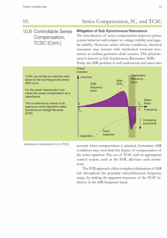
There’s a better way 73
Series Compensation, SC, and TCSC10.
Virtual rectance
Frequency
Ideal SVR
Fixed Capacitor
SSR frequency band
Inductive
Capacitive
Transmition frequency band
Increasing boost level
Impedance characteristics of a TCSC.
fN0
Stator Rotor0
fN
TCSC can act like an inductive reac-tance for the low frequencies where SSR occur.
For the power frequencies it per-ceives the series compensation as a capacitance.
This is achieved by means of an ingenious control algorithm called Synchronous Voltage Reversal (SVR)
10.6 Controllable Series Compensation, TCSC (Cont.)
Mitigation of Sub Synchronous ResonanceThe introduction of series compensation improves power system behavior with respect to voltage stability and angu-lar stability. However, under adverse conditions, electrical resonance may interact with mechanical torsional reso-nances in turbine-generator shaft systems. This phenom-enon is known as Sub Synchronous Resonance (SSR). Today the SSR problem is well understood and taken into
account when compensation is planned. Sometimes SSR conditions may even limit the degree of compensation of the series capacitor. The use of TCSC with an appropriate control system, such as the SVR, alleviates such restric-tions.
The SVR approach offers complete elimination of SSR risk throughout the potential subsynchronous frequency range, by making the apparent reactance of the TCSC in-ductive in the SSR frequency band.