Embed Size (px)
Citation preview

i
THERMAL HYDRAULIC AND SAFETY ANALYSIS OF HEAT TRANSFER
AND DISTRIBUTION IN THE GHANA RESEARCH REACTOR-1
(GHARR-1) CORE USING STAR-CCM+ CFD CODE
A thesis presented to the:
Department of MEDICAL PHYSICS
GRADUATE SCHOOL OF NUCLEAR AND ALLIED SCIENCES
UNIVERSITY OF GHANA
BY
SIMBARASHE MANGENA, 10542174
Bsc, Midlands State University, Zimbabwe, 2009
In partial fulfillment of the requirements of the award of
MASTER OF PHILOSOPHY
IN
NUCLEAR SCIENCE AND TECHNOLOGY PROGRAM
JULY, 2016
University of Ghana http://ugspace.ug.edu.gh

ii
DECLARATION
This thesis is a result of research work undertaken by Simbarashe Mangena in the
Department of Medical Physics, School of Nuclear and Allied Sciences (SNAS),
University of Ghana, under the supervision of Professor G. Emi-Reynolds and Dr. V.Y.
Agbodemegbe.
……………………… Date: ……………………….
Simbarashe Mangena
(Student)
……………………… Date: ………………………
Prof. G. Emi Reynolds
(Principal Supervisor)
……………………… Date: ……………………...
Dr. V. Y. Agbodemegbe
(Co-supervisor)
University of Ghana http://ugspace.ug.edu.gh

iii
ABSTRACT
Operational power of a nuclear reactor core is limited by thermal considerations. In
principle, the allowable core power is restricted by the rate at which the heat can be
transferred from the fuel to the coolant. Unlike in conventional combustion facilities
where the heat is released in gas-flows, heat in the nuclear reactor core is mainly released
in the structural material. If not properly removed the structural materials inevitably melt
causing release of radioactive material.
STAR-CCM+ CFD code was used to perform thermal hydraulic analysis of the Miniature
Neutron Source reactor also known as the Ghana Research Reactor-1 (GHARR-1). The
reactor has a Highly Enriched Uranium (HEU) core consisting 344 fuel pins arranged in
10 multi-concentric circle layers at a pitch distance of 10.95 mm. The present study
however considered only the first two concentric rings with varying power of 15 to
30kW. The choice of the first two concentric rings was informed by the results of the
computation of local power peaking factors based on power densities. The result
indicates that the maximum radial peaking factor of 2.02 occurred at the mid-plane of the
core while the maximum axial peaking factor of 1.57 was at the region of the second ring.
The extent of the domain considered in this work was also limited by the computational
resources available.
Analysis of the temperature, pressure, mass flow rate and turbulent intensity in the first
two concentric rings was performed to assess the steady state Thermal hydraulic
behaviour of GHARR-1 core under natural convection cooling. Computational simulation
was performed at 15 and 30 kW at a fixed mass flow rate of 0.11 kg/s. The mass flow
rate was varied from 0.11 to 0.15 kg/s in steps of 0.02 kg/s at a fixed power of 30 KW.
University of Ghana http://ugspace.ug.edu.gh

iv
Effective heat transfer and cooling of the reactor was achieved at the maximum coolant
mass flow rate. Surface Average temperature increased along the flow channel from the
inlet to the outlet in conformity with operating trends reported in the GHARR-1 Safety
Analysis Report. The highest surface average temperature in the normal operating power
range (15-30kW) was observed to be 296.21K at 30 kW and coolant mass flow rate of
0.11kg/s. The hottest channel is located between the inner and outer ring on the triangular
pitch distance bounded by rods 4, 5 and 14.
The hottest segment has a temperature of 301.85K and is located at an axial distance of
0.2020cm. This is below the maximum cladding Temperature of 333.15K hence the
reactor is operating safely. Computed Distribution of the mass flow rate generated in the
domain varies proportionally with the assigned inlet mass flow rate for the normal
operating powers (15-30kW) A turbulence surge at the inlet due to instantaneous
injection of fluid coupled with a drop as a result of development of the flow was
observed.
A general turbulence buildup was also observed as the flow develops and the fluid
stabilises. Turbulent intensity was observed to peak at the upper part of the fuel rods
consistent with the predictions of the GHARR-1 Safety Analysis Report. All computed
accident situation temperatures were below the melting point of the U-Al alloy satisfying
regulatory requirements for safe operations.
University of Ghana http://ugspace.ug.edu.gh

v
DEDICATION
This work is dedicated to my parents Mr and Mrs E.P Mangena, my sisters Grace
Mangena-Chigeza and Tariro Mangena-Jemwa, my nieces Philipa Chigeza, Amara
Jemwa and Tamara Jemwa, my nephews Flynn and Flloyd Chigeza. Last but not least my
girlfriend Lorraine Rutendo Zhou for the time endured.
University of Ghana http://ugspace.ug.edu.gh

vi
ACKNOWLEDGEMENTS
I would like to gratefully acknowledge the International Atomic Energy Agency (IAEA)
and the Government of Zimbabwe for awarding me the opportunity to undertake studies
in Ghana.
My profound gratitude to my supervisors Prof G. Emi- Reynolds and Dr V.Y
Agbodemegbe whose guidance, conscientiousness and meticulous attention to detail was
instrumental in the production of this thesis.
This acknowledgement would be incomplete without mention of Mr Edward Shitshi
whose immense support was unquantifiable. Thank you “old man of SNAS” and may our
dear Lord bless you abundantly. In the same vein, profound gratitude also goes to Prof
Emeritus E.H.K Akaho, Prof C. Shandorf, Prof J.J Fletcher, Dr S.K Debrah, Dr
Ampomah Amoako, Dr R.B. M Sogbadji, Dr Danso, Rev Dr A. Bamford, Dr H.C Odoi
and Dr R. Abrefah for the priceless impartation of knowledge. Hats off to the
Management of the Radiation Protection Authority of Zimbabwe for their confidence in
me and awarding me this opportunity. Special mention to the Chief Executive officer Mr
R.M Severa. May God bless and prosper you in all dimensions.
My Father, mentor and role model since childhood Mr E.P Mangena, an ocean of
wisdom, knowledge and experience. I am proud of you Dad, I owe it all to you. Thank
you for continuously refining and polishing me to be a man that people take pride in.
I would also like to record my heartfelt thanks to my family, friends, advocates, CD-
ADAPCO and everyone who contributed in many different ways and provided
continuous support in this effort.
University of Ghana http://ugspace.ug.edu.gh

vii
TABLE OF CONTENTS
TABLE OF CONTENTS vii
LIST OF TABLES x
LIST OF FIGURES xi
NOMENCLATURE xiii
CHAPTER 1 1
INTRODUCTION 1
1.1. Background 1
1.2 Overview of the GHARR-1 2
1.3 Heat Transfer in the GHARR-1 Core 5
1.4 Statement of the Problem 6
1.5 Objectives 7
1.6 Relevance & Justification 7
1.7 Scope and Limitation 8
1.8 Thesis Structure 8
CHAPTER TWO 9
LITERATURE REVIEW 9
2.1 Previous Related Work on GHARR-1 and other MNSRs 9
2.2 Operational Limits and Conditions 16
2.2.1 Specifications for Fuel Parameters 16
2.2.2 Reactor Core Specifications 16
2.3. Heat Removal and Transfer in MNSR 17
2.3.1 Heat Generation in the fuel meat 17
2.3.2 Heat Transfer to the Fuel Clad 18
University of Ghana http://ugspace.ug.edu.gh

viii
2.3.3 Natural Convection 20
2.3.4 Heat flux Profile 22
2.3.5 Power Peaking Factor (PPF) 23
2.4 Safety Considerations for Thermal Hydraulic Analysis of a Nuclear Reactor core: 24
2.4.1 Failure of Heat Removal and Consequences 24
2.4.2 Safety Design and Operational Limits to be observed 25
2.4.3 Significance of the Research in Monitoring Safety Design and Operational Limits 26
2.4.4 Safety Related Thermalhydraulic Parameters 27
2.5 STAR-CCM+ Simulation 28
2.5.1 Background 28
2.5.2 Principle of Operation 28
2.6 Governing Equations 31
2.6.1 Continuity Equation 31
2.6.2 X- Component of momentum equation 32
2.6.3 Y- Component of momentum equation 32
2.6.4 Z- Component of momentum equation 33
2.7 Meshing Models 34
2.7.1 Surface Remesher 34
2.7.2 Polyhedral Meshing Model 34
2.7.3 Prism Layer Mesher 35
2.8 Physics Models 35
2.8.1 K-Epsilon model 35
2.8.2 Turbulent Boundary Layer 37
2.8.3 Wall Y+ 38
CHAPTER THREE: 40
METHODOLOGY 40
3.1 Experimental 40
University of Ghana http://ugspace.ug.edu.gh

ix
3.2 CFD Model Description 41
3.2.1 Geometry Modelling 41
3.2.2 Mesh Generation 43
3.2.3 Physics Modelling 44
3.3 Calculation of Power Peaking Factors 47
3.4 Calculation of Heat Flux 47
CHAPTER FOUR 49
RESULTS AND DISCUSSIONS 49
4.1. Introduction 49
4.2 Analysis of Flow Parameters at Fixed Mass Flow Rate 51
4.2.1 Flow Parameters analysis at 15kW 51
4.2.2 Flow Parameters analysis at 30 kW 54
4.3 Analysis of Flow Parameters at Fixed Power and Varying Mass Flow Rate 58
4.3.1 1 Flow Parameters analysis at 30 kW and Mass Flow Rate of 0.13 kg/s 58
4.3.2 Flow Parameters analysis at 30kW and Mass Flow Rate of 0.15 kg/s 61
4.4 Analysis of Temperature at low Mass Flow Rate 65
4.4.1 Temperature at 15 kW at Mass Flow Rate of 0.01 kg/s 65
4.4.2 Temperature at 30 kW at Mass Flow Rate of 0.01 kg/s 66
CHAPTER FIVE 67
CONCLUSION AND RECOMMENDATIONS 67
5.1. Conclusion 67
5.2. Recommendations 68
REFERENCES 69
APPENDICES 73
University of Ghana http://ugspace.ug.edu.gh

x
LIST OF TABLES
1.1: Technical Specifications for GHARR-1 ...................................................................... 4
1.2: Thermal Hydraulic Specifications for GHARR-1 ...................................................... 5
3.1: Meshing Specifications .............................................................................................. 43
3.2: Initial Conditions ....................................................................................................... 44
3.3: Physics and Bondary Specifications .......................................................................... 45
University of Ghana http://ugspace.ug.edu.gh

xi
LIST OF FIGURES
1.1: GHARR-1 Core Showing the 10 Concentric Rings. ................................................... 2
1.2: Schematic Diagram of the MNSR(Side View). ........................................................... 3
1.3: Heat Transfer under Natural Circulation ..................................................................... 6
2.1: Fuel Channel with a single Rod ................................................................................. 19
2.2: Fuel Rod Heat Transfer Geometry............................................................................. 22
2.3: Illustration of the finite volume method .................................................................... 29
3.1: Schematic Diagram of the first 2 concentric rings of GHARR-1 Core . ................... 41
3.2: Plan view of the Computational Geometry................................................................ 42
3.3: Transparent view of the Geometry .......................................................................... 42
3.4: Mesh Scene of the Computational Geomerty ............................................................ 44
4.1: Residual Plot of a Converged Simulation .................................................................. 49
4.2: Schematic Diagram of a Constrained Plane .............................................................. 50
4.3: Comparison of Temperature in the 2 Rings at 15 kW and 0.11 kg/s ......................... 51
4.4: Comparison of Pressure in the 2 Rings at 15 kW and 0.11 kg/s................................ 52
4.5: Comparison of Mass Flow Rate in the 2 Rings at 15 kW and 0.11 kg/s ................... 52
4.6: Comparison of Turbulent Intensity in the 2 Rings at 15 kW and 0.11 kg/s .............. 53
4.7: Comparison of Temperature in the 2 Rings at 30 kW and 0.11 kg/s ......................... 54
4.8: Comparison of Pressure in the 2 Rings at 30 kW and 0.11 kg/s................................ 55
4.9: Comparison of Mass Flow Rate in the 2 Rings at 30 kW and 0.11 kg/s ................... 56
4.10: Comparison of Turbulent Intensity in the 2 Rings at 15 kW and 0.11 kg/s ............ 57
4.11: Comparison of Temperature in the 2 Rings at 30 kW and 0.13 kg/s ....................... 58
University of Ghana http://ugspace.ug.edu.gh

xii
4.12: Comparison of Pressure in the 2 Rings at 30 kW and 0.13 kg/s.............................. 59
4.13: Comparison of Mass Flow Rate in the 2 Rings at 30 kW and 0.13 kg/s ................. 59
4.14: Comparison of Turbulent Intensity in the 2 Rings at 30kW and 0.13 kg/s ............. 60
4.15: Comparison of Temperature in the 2 Rings at 30 kW and 0.15 kg/s ....................... 61
4.16: Comparison of Pressure in the 2 Rings at 15 kW and 0.15 kg/s.............................. 62
4.17: Comparison of Mass Flow Rate in the 2 Rings at 30 kW and 0.15 kg/s ................. 63
4.18: Comparison of Turbulent Intensity in the 2 Rings at 15 kW and 0.15 kg/s ............ 64
4.19: Temperature Variation in the Hottest Channel at 15 kW and 0.01 kg/s…………..65
4.20: Temperature Variation in the Hottest Channel at 30 kW and 0.01 kg/s…………..66
University of Ghana http://ugspace.ug.edu.gh

xiii
NOMENCLATURE
Roman Letters
.
Q Heat generation rate
G Energy produced per fission
N Number of fissionable nuclei per unit volume
fV Volume of the fuel
''q Heat flux (heat transferred per unit area
K Thermal conductivity of the fuel pellet
T Temperature
R Radius of the fuel pellet
h Specific Enthalpy
ch Convective heat transfer Coefficient
gh Gap conductance
F Buoyancy force per unit volume
g Acceleration due to gravity
Gr Grashof’s number
L Characteristic length of coolant channel
Ra Rayleigh Number
Pr Prandtl number
U, V and W Momentum components in x, y and z directions
u, v and w Velocity components in x, y and z directions
S Source term
University of Ghana http://ugspace.ug.edu.gh

xiv
c Specific heat capacity
P Pressure
B Constant
Fq Power peaking factor
Ps Power in each fuel rod segment
Pr Operating power
As Surface area
k turbulent kinetic energy
Y+ Dimensionless variables with respect to the wall conditions
Greek Letters
f Microscopic fission cross section of the fuel
Neutron flux
Material density
Time
Volumetric thermal expansion coefficient
Change in a specific quantity
Viscosity
v Coolant velocity
ε Turbulent dissipation
ω Specific dissipation rate
Thermal diffusivity
Viscous Stresses
Boundary layer thickness
University of Ghana http://ugspace.ug.edu.gh

xv
Constant
Imposed Heat Flux
Ʃ Summation
Subscripts
f Fuel
c Cladding
FS Fuel pellet surface
Cl Cladding inner radius
CS Cladding outer radius
W Bulk Coolant
AV Average
Max Maximum
x, y, and z Direction components
i internal energy
i, j and k Direction Components in Cartesian tensor form
t Turbulent
b Buoyancy
w Wall
Scalar quantity
v Volume
s Surface
University of Ghana http://ugspace.ug.edu.gh

xvi
Abbreviations
GHARR-1 Ghana Research Reactor 1
MNSR Miniature Neutron Source Reactor
HEU Highly Enriched Uranium
STAR-CCM+ Simulation of Turbulent flow in Arbitrary Regions C++ Based
CFD Computational Fluid Dynamics
U-Al Uranium- Aluminium
Cd Cadmium
CIAE China Institute of Atomic Energy
SAR Safety Analysis Report
SLOW-POKE Safe Low Power Kritical Experimental
NAA Neutron Activation Analysis
PARET Program for the Analysis of Reactor Transients
MCNP Monte- Carlo N-Particle
MATLAB Matrix Laboratory
DNBR Departure from Nucleate Boiling Ratio
MDNBR Minimum Departure from Nucleate Boiling Ratio
COMSOL Computer Solutions
3D-CAD 3-Dimensional Computer Aided Design
RELAP Reactor Excursion and Leak Analysis Program
NIRR-1 Nigeria Research Reactor-1
PPFF Power Peaking Factors
CHF Critical Heat Flux
University of Ghana http://ugspace.ug.edu.gh

xvii
CHFR Critical Heat Flux Ratio
SIMPLE Semi Implicit Method for Pressure Linked Equations
NNRI National Nuclear Research Institute
S/No Specification Number
TLOFA Total loss of flow accident
GAEC Ghana Atomic Energy Commission
NIST National Institute of Standards and Technology
Tke Turbulent Kinetic Energy
Tdr Turbulent Dissipation Rate
LEU Low Enriched Uranium
University of Ghana http://ugspace.ug.edu.gh

1
CHAPTER 1
INTRODUCTION
This chapter outlines the phenomenon of heat transfer in the GHARR-1 and establishes
the justification for the study in association with the problem statement. It also gives
insight on the scope of the work as a regulatory requirement.
1.1. Background
Nuclear energy generation is strictly proportional to the generation of the neutron flux.
Therefore depending on the size of the reactor core, there is a limit to the amount of fluid
employed for the removal of thermal heat generated. Other parameters may affect the
level of generated heat within the core, but it is limited by the ability of the fluid to cool
the fuel pins. [1].
In this vein, adequate description of the process of transferring the fission heat released in
materials due to nuclear reactions is both paramount and fundamental for the safe
utilization of the thermal energy in the provision of useful heat. The study therefore seeks
to provide knowledge of the heat generated in the core of the GHARR-1 in the first two
concentric rings.
In the GHARR-1, U-Al alloy is used as the fuel meat and is in contact with the cladding,
providing a small contact resistance. Due to the low power density the centre temperature
of the meat is almost the same as cladding temperature when operating at the same
reactor power. The temperature drop across the cladding is about 1oC. 344 fuel pins
constitute the reactor core configuration at a nominal power 30 kW [2]. The configuration
of fuel pins comprises arrangement in 10 multi-concentric circle layers at a pitch distance
of 10.95 mm as shown in Figure 1.1
University of Ghana http://ugspace.ug.edu.gh

2
Figure 1.1: GHARR-1 Core showing the 10 concentric rings [2]
The work to be performed seeks to make use of features available in Computational Fluid
Dynamics (CFD) models with the aim to analyse heat transfer and distribution in the
GHARR-1 core. The present study will however consider the first two rings of the
GHARR-1. STAR-CCM+ CFD code shall be employed for this application.
1.2 Overview of the GHARR-1
The GHARR-1 is a Miniature Neutron Source Reactor (MNSR) with a tank-in-pool
design and a maximum power of 30kW similar to the Canadian SLOWPOKE (Safe Low
Power Critical Experiment) reactor. It was designed, manufactured and constructed by
China Institute of Atomic Energy (CIAE). The GHARR-1 is fueled by Highly Enriched
Uranium (HEU) (90.2% enrichment) in aluminium alloy (UAl4) fabricated into pins
4.3mm in diameter housed in a 0.6mm thick aluminium cladding. Each of the 344 fuel
elements are concentrically arranged in 10 rings (figure 1.1) in the fuel assembly with a
total length of 248mm and an active length of 230mm. The fuel assembly additionally
contains 4 tie rods and 6 dummy pins mounted on a 50 mm thick bottom-Be reflector
surrounded by a 100 mm thick annular-Be reflector in addition to a top-shim Be reflector
University of Ghana http://ugspace.ug.edu.gh

3
of variable thickness. A stainless steel cladded Cadmium (Cd) control rod is inserted and
withdrawn through a central guide tube covering the active length of the core. The single
control rod regulates the reactor power, compensates reactivity and shuts down the
reactor during normal and abnormal operations [3]. Natural convection is employed for
cooling the reactor which operates to a maximum thermal neutron flux of 1x10¹² n/cm2s.
Figure 1.2 shows a schematic diagram of the MNSR. The reactor comprises 5 major
components namely the reactor assembly, control console, auxiliary systems, irradiation
system and the pool. It is designed for use in universities, hospitals and research institutes
mainly for neutron activation analysis, production of short lived radioisotopes, education
and manpower development.
Figure 1.2: Schematic diagram of the MNSR (side view) [4]
Technical and thermal hydraulic specifications of the GHARR-1 are provided in tables
1.1 and 1.2 respectively.
University of Ghana http://ugspace.ug.edu.gh

4
Table 1.1: Technical Specifications for GHARR-1
Parameter Description
Reactor Type Tank in pool
Rated Thermal Power 30kW
Fuel UAl4
U-235 Enrichment 90.2%
Core shape Cylinder
Core Diameter 23.1cm
Core Height 23.0 cm
Core loading 990.72 g
Number of fuel Elements 344
Number of dummy rods 6
No. of Irradiation Channels 10
Inner Channels 5
Flux in inner channel 1x10¹² n/cm2s
Flux in outer channel 5x10¹¹ n/cm2s
Reactor Cooling Mode Natural Circulation
Height of inlet orifice 6mm
Height of Outlet orifice 7.5mm
Diameter of fuel meat 4.3mm
Diameter of fuel Element 5.5mm
Excess Reactivity 3.9mK
University of Ghana http://ugspace.ug.edu.gh

5
Table 1.2: Thermal Hydraulic Specifications for GHARR-1
Initial Condition Magnitude
System Pressure 1bar
Reactor Water mass flow Rate 0.112 kg/s
Pool Water mass flow Rate 0.224-0.280kg/s
Inlet water temperature 303.15 K
Maximum cladding Temperature
at 30kW
333.15 K
Coolant Density 1000kg/m3
1.3 Heat Transfer in the GHARR-1 Core
The GHARR-1 core is located 4.7m under 1.5m3 of water close to the bottom of a
watertight reactor vessel. The water in the reactor relies upon natural convection and is
the primary heat transfer medium which additionally serves the purpose of radiation
shielding and moderation. A water-cooling coil located near the top of the vessel is also
used for heat extraction. The water-filled reactor vessel is in turn immersed in a water-
filled pool of 30m3. Cold water is drawn through the inlet orifice by natural convection
and flows through the hot fuel elements then exists the core through the outlet orifice.
The heated water rises to mix with the large volume of water in the reactor vessel and to
the cooling coil. Heat passes through the walls of the container and is dissipated in the
pool water. The flow regime of the coolant in the core is at the transient phase from
laminar flow to turbulent flow. The flow transition occurs when there is an increase in
power as a result turbulence increases in the coolant towards the upper part of the fuel
elements where the buoyancy force in natural circulation must overcome the friction [3].
A diagrammatic representation of heat removal under natural circulation is shown in
Figure 1.3.
University of Ghana http://ugspace.ug.edu.gh

6
Figure 1.3: Heat transfer under natural circulation [5]
1.4 Statement of the Problem
There is no theoretical upper limit to the power production in a nuclear reactor as long as
the heat released can be safely removed. From a safety analysis point of view, literature
lacks comprehensive numerical data that can be used to predict heat transfer in the
GHARR-1 core. Current knowledge [11, 19] is limited as a result of adaptations of the
geometry consistent with the capabilities of analysis codes. Neutronics codes employed
in previous studies were able to model the entire geometry of the GHARR-1 but they are
limited to evaluation of Neutronics parameters. Studies performed by S. Mohammed et
al., [19] modified the core and represented it as a single fuel pin. There is need for a more
accurate representation of the core consistent with the available computational resources.
The work seeks to accurately analyse heat transfer and distribution in the actual geometry
of the GHARR-1 core focussing on the first two concentric rings. The study is expected
to satisfy the regulatory requirement of ensuring safety of operation of the reactor at all
times [6]
University of Ghana http://ugspace.ug.edu.gh

7
1.5 Objectives
To perform thermal hydraulic analysis of the heat generated in the GHARR-1 core
paying particular attention to heat distribution from one ring to the other between the first
two concentric rings.
Specific Objective
1) To evaluate the steady state thermal hydraulic behaviour of GHARR-1 core under
natural convection cooling by numerical simulation using STAR-CCM+ CFD code.
2) To perform fluid channel mapping and zoning of the GHARR-1 core in a bid to
analyse heat transfer and distribution.
3) To provide adequate knowledge of the heat generated in the core of the GHARR-1
Miniature Neutron Source Reactor (MNSR)
4) To determine the extent to which failure of the heat transfer will compromise safe
operation of the reactor based on limits approved by the Regulatory Authority.
1.6 Relevance & Justification
Nuclear thermal hydraulics is the science providing knowledge and mathematical tools
for adequate description of the process of transferring the fission heat released in
materials due to nuclear reactions into its environment. Properly arranged and controlled
processes achieve this target. Improperly arranged processes or inappropriate controlled
processes may lead to damages, resulting in partial or in some cases total loss of
investment together with loss of life. Nuclear thermal hydraulics is thus a substantial part
of reactor safety [7].
Accurate knowledge of the heat source is a prerequisite for analysis of the temperature
field. It is on this basis that nuclear and physical properties of the fuel, coolant and
structural material are defined. Both steady state and transient conditions of the reactor
require the coupling of neutronic and thermal analysis. Thermal analysis is performed in
order to predict the temperature field in the reactor core [8].
University of Ghana http://ugspace.ug.edu.gh

8
The use of computer based simulations helps to accurately analyse heat transfer in the
GHARR-1 core in a bid to assess and enhance operational safety. In view of the above
discourse, the study serves to provide analysis of heat transfer within the GHARR-1 core
as a means of operational analysis for safety assessment during normal operation
1.7 Scope and Limitation
In a bid to optimize the available computational resources, the study will be limited to
analysis of the first two concentric rings. Consistent with computations of local power
peaking factors based on power densities as reported in the Safety Analysis Report, the
maximum radial peaking factor of 2.02 occurred at the mid-plane of the core and the
maximum axial peaking factor of 1.57 was at the region of the second ring with 6 fuel
elements near the centre of the core as reported in the Safety Analysis Report. Analysis of
heat transfer at these regions of maximum heat release will thus give an overall view of
heat transfer in the core and hence the safety of the facility.
1.8 Thesis Structure
This thesis comprises five chapters. Chapter one provides an introduction and
background to the study. It also emphasizes the importance of this work and its
contribution to current knowledge on heat transfer and distribution in research reactors.
Chapter two gives insight on the work performed in the study of heat transfer and
distribution in MNSRs and highlights the knowledge gaps that need to be addressed by
this research. A comprehensive discussion of the fundamentals of the STAR-CCM+ code
and its relevant features utilized in the computational modelling and analysis of the
GHARR-1 is also undertaken in this chapter. Chapter three vividly outlines the
methodology employed for the analysis of heat transfer and distribution in the GHARR-
1. It also discusses the geometry design, computational models used, boundary conditions
and relevant parameters utilized in the research as well as explanations of the various
processes undertaken by the code during computation. The results obtained from the
study are clearly and logically presented in Chapter 4. Chapter five concludes the study
and gives an overall summary of the research, recommendations, lessons learnt, overall
contribution to current knowledge and possible recommendations for future studies.
University of Ghana http://ugspace.ug.edu.gh

9
CHAPTER TWO
LITERATURE REVIEW
Computational fluid dynamics codes provides a comprehensive understanding of heat
transfer processes and fluid flow in complex geometries of nuclear reactors. In this work
the application of CFD to undertake thermal-hydraulic analysis of the Miniature Neutron
Source Reactor (MNSR) at the Ghana Atomic Energy Commission was carried out. This
chapter presents a review of relevant literature on the work performed in the study of heat
transfer on GHARR-1 as well as the approach adopted in the study of other Miniature
Neutron Source Reactors (MNSRs) and the extent and limitations in these previous
efforts directed at the study of MNSRs.
Commercial nuclear power reactors are designed to achieve optimum thermal hydraulic
performance while maintaining sufficient safety margins. Research reactors, while not
aiming at optimum thermal-hydraulic performance, are also required to permit sufficient
safety margins between normal operations and hence ensure fuel and cladding integrity
[9]. The work reported in this thesis serves to complement the previous work and provide
a framework for operational safety analysis.
2.1 Previous Related Work on GHARR-1 and other MNSRs
Miniature Neutron Source Reactors (MNSRs) are Chinese versions of the Canadian Safe
Low Power Kritical Experimental (SLOW-POKE) reactors. There are four operational
MNSRs in China, while Ghana, Iran, Nigeria, Pakistan and Syria have one each [10]. The
Ghana Research Reactor 1 (GHARR-1) was commissioned in March 1995 [11]. It has
been used mainly as a teaching and training reactor, Neutron Activation Analysis (NAA)
and small scale radioisotope production [4]. Studies on the GHARR-1 have been directed
towards characterizing the core by computer simulation together with experimental work.
These previous works provided information on, neutron fluxes, reactor parameters,
University of Ghana http://ugspace.ug.edu.gh

10
reactor transients, power peaking factors and burnup. However, simulation and
experimental work with regards to coolant/moderator temperature distribution is limited.
Ampomah- Amoako et al., performed transient analysis of the GHARR-1 using PARET-
thermal hydraulics code for the insertion of 2.1 mK, 4 mK and 6.71 mK reactivities.
Program for the Analysis of Reactor Transients (PARET) code enables the reactor core to
be represented by up to four regions with different power generation, coolant mass flow
rate and hydraulic parameters. This setup mimics fuel pins and their associated coolant
channels. Solution of the one-dimensional heat conduction equation enabled computation
of heat transfer in each fuel element solution up to a maximum of 21 axial segments. The
geometry of the present work was designed consistent to the maximum axial segments of
the PARET code [12]. Power across the 21 axial sections was obtained from an MCNP
neutronic computation [13, 14]. Power peaking factors were calculated from this work
and used to compute heat fluxes that were used to study heat transfer in the present work.
Transient Temperature profiles within the fuel pin following a sudden loss of coolant
accident were investigated by C.J Adjei et al., The transient conditions entailed the
operation of the research reactor at maximum power (30 kW) in steady state and
suddenly shutting down due to total loss of coolant without generation of subsequent
internal heat together with decay heat from the fuel pins. Equations of transient
temperature distribution were formulated mathematically and solved analytically using
Bessel functions. The results obtained showed a high transient temperature distribution at
the fuel element centreline, the least temperature was recorded at the fuel clad surface
[15]. Although axial heat conduction was assumed to be negligible in their analysis, the
present work provides detailed axial analysis of temperature, pressure mass flow rate and
turbulent intensity in the core by through the use of STAR-CCM+ Computational Fluid
Dynamics code. Furthermore, safety analysis of both normal operation and accident
conditions will be performed.
N.A. Adoo et al., determined thermal hydraulic data for the GHARR-1 under reactivity
insertion transients using the PARET/ANL code. The following parameters were
analysed:
University of Ghana http://ugspace.ug.edu.gh

11
peak clad and coolant temperatures
temperature and void coefficients of reactivity
power distribution and power peaking factors
Heat flux at the hot spot.
Peak clad and coolant temperatures were observed to range from 59.18 ◦C to 112.36 ◦C
and 42.95 ◦C to 79.42 ◦C respectively. Calculations of the Departure from Nucleate
Boiling Ratio (DNBR) satisfied the design criteria for which no boiling occurs in the
reactor core consistent with operational safety limits. The resultant thermal hydraulic data
generated by the PARET code indicated that the high inherent safety feature of GHARR-
1 limits power excursion and escalation of the cladding temperature as a result of the high
negative reactivity feedback of the moderator. The advent of Computational analysis of
the clad and coolant temperatures was a major development from the previous analytical
transient temperature profile studies performed by Adjei et al [16]. The present work will
employ injection of heat flux calculated from power peaking factors and analysis of the
steady state thermal hydraulic behaviour of GHARR-1 under natural convection cooling.
Analysis of thermal hydraulic transients was performed by S.Yamoah et al., A
mathematical model was used to simulate the effect of the pool upper section cooling
coils on the thermal-hydraulic behaviour of the GHARR-1. The model was based on the
lumped parameter description numerically solved by Matlab/Simulink. The cooling coil
mechanism for heat removal in the core is based on circulating water from the coil in the
reactor vessel to a refrigeration unit (chiller) which cools the water and returns it to the
coil. The reactor vessel and core are cooled by the water as it circulates and heat is
transferred by convection from the vessel wall to the reactor pool. The model
incorporates fuel grids, cooling coils and radiant energy from the clad. An energy balance
based on the average temperatures in these components was performed and partial
differentials solved for the diffusion of heat through each fuel element in the core.
Comparison of the predictions of model with experimental data showed good agreement
of results [5]. The work performed augmented earlier thermal hydraulic studies which
were conducted under reactivity insertion. In contrast to the lumped parameter model, the
present work involves a finite volume discretization of the reactor core by application of
University of Ghana http://ugspace.ug.edu.gh

12
the STAR-CCM+ code and will focus on analysing heat transfer within the fuel rods and
coolant circulating in the core.
Kyei A.Y. et al., modelled the velocity profile of the coolant flow in the GHARR-1 flow
channel using a finite difference scheme by the Marker and Cell method. The model was
based on mathematical formulation of the Navier-Stokes equations using a finite
difference method for the coolant flow channel of the GHARR-1. The following
assumptions were made;
Coolant flow through the core was laminar.
The fluid is incompressible with constant properties.
The flow was between parallel plates.
The geometry was considered as a plane
The fuel channels were discretized into nodal points in a bid to model the coolant flow
Velocity at the nodal points was obtained from computations using the Navier-Stokes
equations. The velocity distribution of the coolant flow at a nominal power of 30 kW was
simulated by MATLAB. Results obtained from the simulation were validated by
COMSOL Multiphysics code using the fluid dynamics module of the Navier- Stokes
equation. Analysis of the results established a velocity distribution which ranged from 0.9
m/s to 1.9 m/s and consequently values for Reynolds Number which ranged from 460 to
970 consistent with the assumption of laminar flow [2]. The present work will employ a
finite volume analysis of the actual flow regime of the GHARR-1 which transitions from
laminar to turbulent on the upper part of the fuel elements. The k-ε turbulence model
shall be used to capture the turbulent flux and its dissipation rate. The mean velocity of
the coolant and its turbulent kinetic energy will be used to determine turbulent intensity at
varying powers.
Control volume finite difference analysis of the transient temperature distribution and
associated induced thermal stresses in the GHARR-1 reactor vessel due to coolant
heating was performed by M Annor- Nyarko et al., The work sought to investigate the
structural integrity of the vessel after 20 years of operation. Heat transfer in the GHARR-
1 comprises temperature distributions within structural materials, thermal stress in solid
components and the flow of reactor coolant. The heat produced by fission in the fuel
University of Ghana http://ugspace.ug.edu.gh

13
elements is transferred to the surface of the cladding by conduction and further
transferred to the flowing coolant and out of the system through the reactor vessel by
natural convection. Thus, heat removal is achieved by natural circulation and water
recirculation. Thermal stresses induced by varied thermal gradients within the vessel wall
along tangential, longitudinal and radial directions were calculated analytically using
Bessel functions. MATLAB was used to generate data for analysis and simulations.
Temperature and thermal stress distributions below the limits imposed by the vessel
material composition (melting point of 933 K and allowable yield stress of 480 MPa)
were obtained from the results. Therefore the structural integrity of the reactor vessel has
been maintained to anticipate the incidence of crack propagation and other premature
failure modes over the operational period [17]. The present work is limited to the core
and will analyse temperature distribution in the fuel and coolant.
T. A. Annafi et al., performed a finite difference analysis of the transient temperature
profile within a fuel element of the GHARR-1. A mathematical model of the transient
heat distribution within the fuel element and related shutdown heat generation rates was
developed [18]. The work utilized the transient temperature profile within the fuel pin of
the GHARR-1 solved analytically using Bessel Functions by Adjei et al., [15] and
shutdown heat generation rates (residual fission power and fission product decay power)
after reactor shutdown due to a reactivity insertion accident estimated by Annafi et al.
The residual fission power and fission product decay power was used as the heat source
and the steady state temperature resembled the initial temperature before shutdown. A
finite difference scheme for the discretization by implicit method was used for analysing
the temperature variation and heat generation. MATLAB was utilized to determine the
temperature distributions within the fuel element on the developed solution algorithms. A
steady state temperature of approximately 341.3 K with a 2 % deviation from that
reported in the GHARR-1 Safety Analysis report was obtained from the simulations. An
approximate average temperature of 444 K lower than the melting point (913 K) the
Aluminium cladding under transient conditions was obtained. The GHARR-1 fuel
element was observed to be stable and thus there would be no release of radioactivity in
the coolant during accident conditions [18]. CFD tools available in STARCCM+ will be
University of Ghana http://ugspace.ug.edu.gh

14
used for the analysis of the temperature profile, pressure, mass flow rate and turbulent
intensity in 18 fuel pins under normal operation in this work.
S. Mohammed et al., investigated heat transfer and distribution in the GHARR-1 core
using Star-CCM+ CFD code. A single fuel rod with 21 axial segments was modelled and
hypothetically assumed to represent the core. The 3D-CAD parametric solid modeller
embedded in the code was used to design the geometry which was then discretized by
polyhedral, prism layer and surface remesher meshing models. Operating conditions of
the GHARR-1set as the boundary conditions for the simulation. Heat flux for each axial
segment was computed from power peaking factors obtained from Ampomah- Amoako
et al [12] and surface area. The heat fluxes were applied at the wall of the flow channel.
Mass flow and pressure were specified as the inlet and outlet boundary conditions
respectively. The turbulent kinetic energy and dissipation rate were solved using a
standard k-ε turbulent model. Experimental data from the GHARR-1 was used to validate
the results of the simulation which were found to be fairly in agreement [19]. The
geometry of the present work is designed to simulate heat transfer and distribution of 18
fuel pins in the first two concentric rings of the GHARR-1 core therefore a
comprehensive and detailed analysis is postulated consistent with the available
computational resources. Computations of hottest and average channels of the core were
based on a single fuel pin in the previous work. The present work provides a more
accurate representation of the hottest channel and envisages an in depth analysis of heat
transfer and distribution due to the fact that all the fuel rods in the actual geometry are
analysed. The present work will therefore provide sufficient knowledge to enable future
analysis of heat transfer and distribution in all 344 pins of the reactor core.
H. Omar et al., performed thermal hydraulics analysis of the Syrian MNSR using Relap 5
Mode3.2/ code. The study entailed simulation of the complete MNSR system using a
RELAP model. Periodic reactivity transients and reactivity insertion accidents were
simulated under conditions of natural circulation. Core inlet and outlet temperature, flow
velocity under nominal operation were calculated with measurements indicating the
correct modelling of reactor core with its complicated geometry. The time development
of the predicted reactor
University of Ghana http://ugspace.ug.edu.gh

15
Power, core inlet and outlet coolant temperature was observed to closely follow the
measured data for the reactivity insertion. The maximum clad temperature was below the
condition of onset of sub-cooled boiling due to the high negative reactivity feedback of
moderator temperature under insertion of total available excess reactivity. The RELAP5
model for Syrian MNSR was therefore shown to be an appropriate model for the
simulation. The predictions by the model were validated by comparison with
experimental data and observed to correlate. Some adaptations were applied to achieve
the best representation of MNSR components consistent with the features available in the
one-dimensional RELAP5 code [20]. The present work will employ STARCCM+ 3-
dimensional Computational Fluid Dynamics (CFD) code for the analysis of heat transfer
and distribution in the core. Application of the code in geometry design is only limited by
available computational resources. An 18 pin reactor core geometry will be used in this
work. Characteristics of the thermal behaviour due to loss of flow will also be
investigated by simulation at low coolant mass flow rate
An experimental testing of coolant flow rate and velocity in the core of Nigeria Research
Reactor-1 was performed by S.A. Agbo et al., The study was aimed at safety assessment
of reactor thermal hydraulic parameters in a bid to improve model predictions.
Experiments to monitor core mass flow rate, coolant velocity, mass flux, density and
Reynolds number at different power levels were conducted in a bid to cater for the
absence of an installed device for measuring core mass flow rate in the NIRR-1. The heat
balance utilized measurements of water inlet and outlet temperature to determine the
mass flow rate through the core. The experiments confirmed the efficiency of natural
circulation for heat removal in the reactor core [21]. The present work entails analysis of
heat transfer and distribution at varying power and coolant mass flow rate using
STARCCM+ CFD code.
University of Ghana http://ugspace.ug.edu.gh

16
2.2 Operational Limits and Conditions
2.2.1 Specifications for Fuel Parameters
(1) Enrichment 90.2 % U-235
(2) U-235 loading per pin 2.88 g
(3) Meat alloy UAl4 in Al
(4) Clad alloy Type 303-1 Al alloy
(5) Dimension of pin 5.5 mm × 248 mm
(6) Clad thickness 0.6 mm
2.2.2 Reactor Core Specifications
(1) Maximum number of fuel elements is 344.
(2) Minimum number of dummy fuel elements is 6.
(3) Minimum number of fuel elements is 343.
(4) Maximum number of dummy fuel elements is 7.
(5) Core geometry is cylindrical and fixed.
(6) Reflectors are beryllium.
(7) Annulus reflector is 102 mm thick.
(8) Bottom reflector is 50 mm thick.
(9) Top reflector is initially water.
(10) Top Be reflector is 0 to 109.5 mm thick.
(11) Reactivity regulators up to 4, as required.
(12) Operating power level is 30 kW nominal [3]
University of Ghana http://ugspace.ug.edu.gh

17
2.3. Heat Removal and Transfer in MNSR
2.3.1 Heat Generation in the fuel meat
Thermal energy released in nuclear reactors is due to the fission process and at a much
smaller degree to the non-fission neutron capture in the fuel, moderator, coolant and
structural material. The smallest integral fuel bearing component of a nuclear reactor is the
fuel element. Heat generated by fission consists almost entirely of fission fragments and
beta particles and is deposited directly in the fuel material. This can be represented
mathematically by the following equation:
ff VGNQ .
(1.00)
Where
.
Q - Heat generation rate (W/sec)
G- Energy produced per fission (W/fission)
N- Number of fissionable nuclei per unit volume (atoms/cm3)
f - Microscopic fission cross section of the fuel (cm2)
- Neutron flux (n/cm2sec)
fV - Volume of the fuel (cm3) [22]
Heat transfer within the fuel pellet is described by the steady state Fourier equation. For
3-dimensional flow in the radial direction:
Tkdr
dTkq ''
(1.01)
Where;
''q - Heat flux (heat transferred per unit area (w/m2)
k- Thermal conductivity of the fuel pellet (w/m.K)
University of Ghana http://ugspace.ug.edu.gh

18
-Temperature gradient (K/m)
The steady state heat balance can thus be written as:
t
TC
k
qT P
'''2 (1.02)
Where:
T- Temperature (K)
'''q -energy generation per unit volume of the fuel material.
k- Thermal conductivity of the fuel pellet (w/m.K)
- Material density
-Heat capacity of the pellet
- Temperature gradient (K/m) [8]
2.3.2 Heat Transfer to the Fuel Clad
The heat deposited in the fuel is transferred by conduction through the fuel across the
boundary between the fuel and cladding and through the cladding to the cladding surface
[22]. A schematic diagram of a fuel channel with a single rod is shown in fig 2.0 below.
University of Ghana http://ugspace.ug.edu.gh

19
Figure 2.1: Fuel Channel with a Single Rod [23]
Heat conduction in the cladding is given by:
tcr
tr
rk
r ccc
1 (1.03)
Where:
r- Radius of the fuel pellet
ck - Conductivity of the cladding (w/m.K)
- Time (sec)
c -Specific mass of the cladding (kg/m3)
cc - Specific Heat (J/kg)
t- Temperature of the clad (K)
h- Specific Enthalpy (KJ/kg)
University of Ghana http://ugspace.ug.edu.gh

20
Heat convection at the cladding surface is given by:
trthr
tk ccc
cc
(1.04)
Where:
ch - Convective heat transfer Coefficient (W/m2K)
cc rt - Temperature of cladding outer surface (K)
t- Coolant Temperature (K)
cr - Radius of the fuel element (m)
Heat Transfer at the fuel-cladding interface is given by:
cccfg rtrthq ('' (1.05)
Where:
gh - Gap conductance (W/m2K)
cf rt - Temperature at the surface of the fuel (K)
cc rt - Temperature at the inner surface of the cladding (K) [23]
2.3.3 Natural Convection
Natural convection occurs as a result of buoyancy forces within the fluid influencing the
motion of the fluid [24]. Buoyancy occurs as a result of thermally induced density
changes producing a fluid density gradient and a proportional body force [24, 25]. The
fluid surrounding the heat source is heated and becomes less dense. The heated fluid rises
to the surface and is replaced by the surrounding cooler fluid which in turn is heated
repeating the same process. Consequently a convection current is formed as a result of
this process [26]. Natural convection is responsible for drawing water through the inlet
orifice in the GHARR-1. The water is drawn through the channels within the fuel
elements and exits through the core outlet orifice [3].
Considering as the density of the “undisturbed” cold fluid and as the density of the
warmer fluid, the buoyancy force per unit volume F of fluid is given by:
gF (1.06)
University of Ghana http://ugspace.ug.edu.gh

21
Where:
g - Acceleration due to gravity
The density varies with temperature as expressed by the following relation:
gT 1 (1.07)
Where:
- Volumetric thermal expansion coefficient
T - Temperature difference between the two fluid regions.
Substituting from equation into equation yields the buoyancy force per unit volume
given as:
TgF (1.08)
The ratio of buoyancy forces to the square of viscous forces in the fluid is described by
Grashof’s number.
2
32
TLgGr
(1.09)
Where:
L - Characteristic length of coolant channel
- Viscosity of the fluid
The buoyancy forces are large compared to the viscous forces at high Gr numbers thus
the fluid particles are held together and therefore convection can occur.
The ratio of thermal energy liberated by buoyancy to the energy dissipated by heat
conduction and viscous drag under natural convection can also be expressed by the
Rayleigh Number.
v
TLgGrRa
3
Pr
(1.10)
Where:
Pr- Prandtl number
University of Ghana http://ugspace.ug.edu.gh

22
v - Coolant velocity
- Thermal diffusivity [24]
2.3.4 Heat flux Profile
The heat flux is the heat transfer rate per unit surface area. While the heat flux can be
referenced to any surface, in reactors the heat flux is most often referenced to the outer
clad surface, i.e. the clad/coolant interface [27]. Figure 2.1 below shows the heat transfer
geometry of a cylindrical fuel rod.
Figure 2.2: Fuel Rod Heat Transfer Geometry [28]
Radial heat flux distribution considers the heat flux from the center of the core out to the
edges and axial heat flux distribution looks at flux from the bottom to the top of the core
[29]. Heat is generated in the fuel pellet radius R and flows radially through the fuel, the
pellet-cladding gap, and the cladding itself to reach the coolant. The axial temperature
variation is relatively small and often neglected due to the small thermal gradient
compared to the thermal gradient in the radial direction. This heat flux flows from the
University of Ghana http://ugspace.ug.edu.gh

23
fuel through the fuel-cladding gap then through the cladding and finally into the coolant.
Heat transfer through the cladding occurs by conduction. Although heat transfer through
the gap occurs through a gas, no flow or convective effects exist. As a result the process
can be thought of as one of conduction with gapgapgap th where gapt is the gap thickness
and gaph the convective heat transfer coefficient in the gap. The temperature drop through
these two hollow cylinders is obtained by solving the heat transfer equations for the
cladding which yield equations 1.11 and 1.12 respectively.
gap
gap
ClFSk
R
tR
qTT2
])(
ln['
(1.11)
C
gap
Cgap
CSClk
tR
ttR
qTT2
])(
)(ln[
'
(1.12)
Where:
FST - Fuel pellet surface Temperature (K)
ClT - Cladding inner radius Temperature (K)
CST - Cladding outer radius Temperature (K)
CT - Cladding wall thickness Temperature (K)
WT - Bulk Coolant Temperature (K) [29]
2.3.5 Power Peaking Factor (PPF)
The power peaking factor is defined as the highest local power density (LPD) divided by
the average power density in the core [30]. Power peaking factors are established to
account for power variations due to non-ideal geometries and/or uncertainties due to
manufacturing tolerances and physical changes during operation [27]. The total power
peaking factor is related to the non-homogenous spatial distribution of the heat flux over
the core. This distribution determines that in certain spots of the core the local heat flux is
University of Ghana http://ugspace.ug.edu.gh

24
higher than the average value. For Thermalhydraulic calculations a cosine profile with a
maximum power peaking factor value of 3 is conservatively adopted [31]. The GHARR-
1 design criteria PPF<4 [3].
The average heat flux ''
Avq is calculated as the power removed by the cooling system
divided by the total heat transfer area.
The maximum operational heat flux ''
Maxq is obtained from the product of the average
heat flux and the power peaking factor (PPF) [31].
2.4 Safety Considerations for Thermal Hydraulic Analysis of a Nuclear Reactor
core:
2.4.1 Failure of Heat Removal and Consequences
S. Adu et al., investigated the core behaviour of the GHARR-1 MNSR during loss of
flow with best estimate code RELAP 5/ MOD3.2. Partial and total blockage of the
coolant to the reactor core transients was performed in a bid to study the behaviour of the
reactor core. Boiling was observed to occur in the blocked channels leading to an
increase in coolant and clad temperatures in the case of partial coolant blockage.
However, the reactor gradually returned to a safe steady state due to unperturbed coolant
flow in adjacent channels. Cladding and coolant temperatures were observed to be below
the melting point of the structural material. In the case of total blockage the calculations
indicated unsafe behaviour of the reactor. The study concluded that natural circulation is
capable of cooling the reactor at 35% blockage without producing any significant threat
to the fuel material integrity [32].
S. Adu et al., propound that due to the upward flow design of the GHARR-1 core
configuration the probability of fuel swelling to block the flow channel is much higher
than that of material falling into the pool to block the flow channel. Conversely, the latter
can occur as a result of some object un-intentionally left in the flow channel during
maintenance work. Nonetheless, since the reactor liquid flow is laminar and there are no
external pumps, dragging material into the core is almost impossible [33].
University of Ghana http://ugspace.ug.edu.gh

25
2.4.2 Safety Design and Operational Limits to be observed
2.4.2.1 Closed tank-in-pool type design structure
This type of reactor design prevents anything from being dropped into the core. From a
radiation protection perspective, the closed tank-in-pool reactor can prevent fission and
activated gas from escaping into the reactor hall. The level of reactor water is the same as
that of the pool water. The reactor water and pool water are separated from each other.
Because of the geometrical arrangement, even if the pool water is lost, the reactor water
and geometric arrangement still provide adequate shielding for the reactor hall against the
radiation from the shutdown reactor [3].
2.4.2.2 Adaptation of natural circulation for cooling
The reactor operates by natural convection to remove heat from the core. Differences in
fluid density and body force (gravity) force the hot fluid to move upwards and cooler
fluid to move down in the large pool establishing a circulation pattern driven by
buoyancy [34].
The water in the reactor is not pressurised and it relies upon natural convection. The
problems of de-pressurisation or coolant flow pump failure are not posed. The reactor
core is immersed in a large reactor vessel containing deionised water, which possesses a
considerable heat capacity. Even under accident conditions, removal of heat is by natural
circulation to this large heat sink [3].
2.4.2.3 Insufficient circulation
Due to the small size of the core, the distance from the inlet orifice to the outlet orifice is
small. The water, after being heated in the core goes out through the upper part of the
core. Part of the water does not get sufficiently cooled before it sinks down, resulting in
part of outlet water being carried back into the core due to siphoning effect. This direct
re-circulation of the part of hot water causes a rise of the inlet water temperature.
University of Ghana http://ugspace.ug.edu.gh

26
This phenomenon is referred to as insufficient circulation. It accelerates the rise in
coolant temperature in the core and shortens the function time of the temperature effect.
Therefore it is impossible to cause the inlet water temperature to rise in such a short time
by heating the core only, but by the coupling action between the inlet and the outlet
coolant. Consequently this offers some benefit to the reactor safety.
2.4.2.4 Use of U-Al alloy as the fuel meat
U-Al alloy possesses high thermal conductivity: The meat is in close contact to the
cladding, providing a small contact resistance.
2.4.2.5 Low linear power density of fuel element of about 3.8 W/cm.
Due to the low power density the centre temperature of the meat is almost the same as
cladding temperature when operating at the same reactor power. The temperature drop
across the cladding is about 1oC [35].
2.4.2.6 Negative feedback effect
This occurs when the temperature difference between the inlet and outlet coolant of
MNSR increases; the buoyancy force and circulating head will increase to make the flow
velocity high, which in turn will limit the rise in temperature and the consequent increase
in power.
2.4.2.7 Limited excess reactivity and reactivity feedback characteristics
Any significant deterioration in heat removal capability will eventually result in an
automatic decrease in reactor power to match up with the new heat removal capacity [3].
2.4.3 Significance of the Research in Monitoring Safety Design and Operational
Limits
The present work will provide in depth understanding of the behaviour of operational
Thermalhydraulic parameters of the GHARR-1 and allow the development of
improved analytical models contributing to safety.
University of Ghana http://ugspace.ug.edu.gh

27
The analysis performed in this work will provide sufficient evidence for the safety of
the GHARR-1 MNSR design as well as its operational ability to keep within its
thermal safety limits in compliance with regulatory requirements.
The application of STAR-CCM+ CFD code in this work will enable modelling of the
actual specifications of the GHARR-1 core configuration which in turn will provide
accurate and reliable prediction of performance of the GHARR-1 under normal and
accident conditions.
The study will provide detailed information on the behaviour of the temperature field
in the GHARR-1 core and coolant which form some of the key concerns in reactor
operations and safety.
Thermalhydraulic studies performed in this work will improve the existing
knowledge on the local temperature and flow fields around fuel geometry and in
internal components of the GHARR-1.
2.4.4 Safety Related Thermalhydraulic Parameters
2.4.4.1 Departure from Nucleate Boiling Ratio (DNBR)
The boiling crisis under subcooled flow boiling conditions is referred to as the departure
from nucleate boiling (DNB). The heat flux at which the boiling crisis occurs is called
critical heat flux (CHF) [36]. The parameter most used to evaluate margin to failure by
boiling crisis is the critical heat flux ratio (CHFR), or departure from nucleate boiling
ratio (DNBR). This is the ratio of critical heat flux to the most limiting heat flux
condition in the reactor [22].
The design criteria of thermal-hydraulic design requires that the burnout ratio or
Departure from Nucleate Boiling Ratio (DNBR) should be larger than the calculated
burnout heat flux i.e. DNBR > 2.5. Under normal operational condition for the GHARR-
1 at power of 30 kW, the maximum temperature is about 70oC, much lower than the
melting point of U-Al alloy, which has a melting point temperature greater than 640oC
[3].
University of Ghana http://ugspace.ug.edu.gh

28
2.4.4.2 Minimum Departure from Nucleate Boiling Ratio (MDNBR)
The performance metric for DNB is the MDNBR which is the minimum ratio of the
Critical Heat flux to the actual heat flux found in the core [37]. For transient calculations,
it was found out that the reactor power increased from zero to 76 kW in about 300s for
the prototype MNSR. The maximum temperature on the outer surface of the cladding was
91.2oC, while the saturation temperature of the reactor water was about 113oC. Therefore,
it is impossible for boiling to occur and there could not be any boiling crisis within the
reactor. Under this transient condition, the heat flux of the fuel elements for burnout was
more than 2.5 times that at the rated power. Therefore, the minimum burnout ratio
MDNBR is at least greater than 2.5 and this fulfils the requirement of thermal-hydraulic
design criteria [3].
2.5 STAR-CCM+ Simulation
2.5.1 Background
STAR-CCM+ is a mathematical idealisation (representation) of real materials such as
solids, fluids and gases. Continuum mechanics is concerned with the behaviour of such
representations. It is based on laws of conservation (of mass, energy, momentum,
moment of momentum and entropy), and is aided by a mathematical apparatus
specifically developed for it [38].
2.5.2 Principle of Operation
STAR-CCM+ is based on numerical solution of equations governing fluid flow by the
finite volume method. This entails transforming the governing equations into a system of
(in general non-linear) algebraic equations, whose subsets approximate each conservation
equation [38]. Time, space and equations relating values of dependent variables are
treated as basic unknowns at a finite number of locations (grid-points) in the calculation
domain. Continuous information contained in the exact solution of differential equations
is replaced with discrete values for the distribution of dependent variables. This process is
University of Ghana http://ugspace.ug.edu.gh

29
called discretization and the algebraic equations involving unknown values of the
dependent variables at each grid point are referred to as discretization equations.
Time discretization entails subdivision of a given time interval into a number of smaller
subintervals or time steps. Space discretization consists of defining a numerical mesh
consisting of a finite number of computational points, thus replacing the continuous
functions by their values at those points. Replacement of individual terms in the
governing equations by algebraic expressions connecting nodal values on a numerical
mesh is called equation discretization [38]. An illustration of the discretization process is
shown in on the diagram below.
Figure 2.3: Illustration of the finite volume method [39]
STAR-CCM+ is inherently a computational fluid dynamics (CFD) code hence it
comprises three main elements: (i) a pre-processor, (ii) a solver and (iii) a post-processor.
Pre-processing entails defining the problem, geometry generation with the aid of inbuilt
geometry modeller together with facilities for importation of external computer aided
design (CAD) models, mesh generation and physics set-up.
Solvers are mathematical software libraries that take the generic form of the problem and
calculate the solution. A discretized version of the transport equations is solved for each
cell in a mesh when the solver is run. Velocity and pressure solvers apply the Semi
University of Ghana http://ugspace.ug.edu.gh

30
Implicit Method for Pressure Linked Equations (SIMPLE) algorithm. The discretized
continuity equation takes the form of a pressure correction equation and estimated values
of its solution are placed at all grid points in a mesh. Tentative values of the coefficients
in the discretization equation are then calculated and the equation is discretized into a set
of linear algebraic equations. The equations are solved to get the new values of velocity
and pressure which are reused to calculate values of the coefficients of the discretization
equation. The process is repeated until further repetitions (iterations) cease to produce
any significant changes in the values of velocity and pressure. The final unchanging state
is called the convergence of the iterations [40].
Energy solvers compute the conservation of energy within each control volume or cell in
the mesh. The solver similarly proceeds from an initial guess of the energy distribution in
each cell and performs a series of iteration to obtain a converged solution of discretized
algebraic equations for the transport and distribution of energy in the domain. The k-ε
turbulent solver computes the solution of transport equations for two scalar properties of
the turbulence. It solves k equation which is a model for the turbulent kinetic energy and
the ε-equation which is a model for the dissipation rate of turbulent kinetic energy in the
domain. The k- ω solver computes the solution of two convective transport equations
namely the turbulent kinetic energy (k) and its specific dissipation rate (ω) in the
computational domain.
Data generated by the solver is post processed using various data visualization tools. The
Plots node, which has a pop-up menu, is the object manager for all monitor plots and XY
plots that have been created in the simulation. It exists even when empty to allow creation
of the first plot, but will typically contain a Residuals plot, which is created automatically
once you start iterating. The plotting features in STAR-CCM+ allow you to create three
kinds of two-dimensional plots:
Monitor plots
Display data from the simulation as it steps through the solution in two varieties namely
monitor plots based on various monitored quantities (scalar and vector) and residual
plots. The residual in each cell represents the degree to which the discretized equation is
University of Ghana http://ugspace.ug.edu.gh

31
satisfied. When the solver is run, a discretized version of the transport equations is solved
for each cell in the mesh. Residual monitors keep a record of this global quantity for each
of the transport equations solved in the continua within the simulation. The residual plot
is a monitor plot that is automatically created from the active residual monitors on semi-
log axes when iterating starts. All active residuals are displayed in the residual plot by
default.
XY plots
Based on the solution data from the simulation and/or simulation data.
Histogram plots
Display data typically for particles [41].
2.6 Governing Equations
Essentially, STAR-CCM+ is a flow solver for the governing integral conservation
equations of mass, momentum and energy [42]. The governing equations of fluid flow
are mathematical statements of the conservation laws of physics:
The mass of a fluid is conserved
The rate of change of momentum equals the sum of the forces on a fluid particle
(Newton’s second law)
The rate of change of energy is equal to the sum of the rate of heat addition to and
the rate of work done on a fluid particle (first law of thermodynamics) [43].
The equations are stated as follows:
2.6.1 Continuity Equation
0
udiv
t
(1.13)
Where:
t
– Change in density with time.
University of Ghana http://ugspace.ug.edu.gh

32
udiv – Convective term, describes net flow of mass out of the element across
its boundaries.
2.6.2 X- Component of momentum equation
Mx
zxxxxx Syyx
p
Dt
Du
(1.14)
Where:
- Density
u- x-component of velocity
p- Pressure
- Viscous Stresses
1st three terms at the RHS- total force in the x-direction on the element due to surface
stresses.
SMx- Source of x-momentum per unit volume per unit time
2.6.3 Y- Component of momentum equation
My
zyyyxyS
zy
p
xDt
Dv
(1.15)
Where:
- Density
v- y- component of velocity
P- Pressure
- Viscous Stresses
1st three terms at the RHS- total force in the y-direction on the element due to surface
stresses
University of Ghana http://ugspace.ug.edu.gh

33
SMx- Source of y-momentum per unit volume per unit time.
2.6.4 Z- Component of momentum equation
Mzzzyzxz S
z
p
yxDt
Dw
(1.16)
Where:
- Density
w- z-component of velocity
P- Pressure
- Viscous Stresses
1st three terms at the RHS- total force in the y-direction on the element due to surface
stresses
SMy- Source of y-momentum per unit volume per unit time. The sign associated with the
pressure is opposite to that associated with the normal viscous stress, because the usual
sign convention takes a tensile stress to be the positive normal stress so that the pressure,
which is by definition a compressive normal stress, has a minus sign [43].
2.6.5 Energy Equation (Temperature Based)
izzyzxzzyyyxyzxyxxx Sz
w
y
w
x
w
z
v
x
v
x
v
z
u
y
u
x
ukgradTdiv
Dt
DTc
Where: (1.16)
- Density
c- Specific heat capacity
k- Thermal conductivity
University of Ghana http://ugspace.ug.edu.gh

34
T- Temperature
- Viscous Stresses
u- x - component of velocity
v- y- component of velocity
w- z-component of velocity
iS - Source of internal energy per unit volume per unit time.
2.7 Meshing Models
A mesh is a discretized representation of the computational domain, which the physics
solvers use to provide a numerical solution. There are different meshing strategies, and
each one has its pros and cons, being more suited for one or other applications. The
domain will be discretized by the application of surface remesher, polyhedral meshing
and prism layer meshing models
2.7.1 Surface Remesher
Remeshes the initial surface to improve the overall quality of an existing surface and
optimize it for the volume mesh models. It is used to retriangulate the surface based on a
user defined target edge length and can also omit specific surfaces or boundaries
preserving the original triangulation from the imported mesh [41].
2.7.2 Polyhedral Meshing Model
The polyhedral meshing model generates a volume mesh which is composed of
polyhedral-shaped cells. It is created from the evolution of an automatically inserted
underlying tetrahedral mesh by the application of a special dualization scheme. It is
numerically more stable, less diffusive and more accurate than an equivalent tetrahedral
mesh. Moreover polyhedral mesh contains approximately five times fewer cells than a
tetrahedral mesh for a given starting surface [41].
University of Ghana http://ugspace.ug.edu.gh

35
2.7.3 Prism Layer Mesher
A prism layer is defined in terms of thickness, number of cell layers, size distribution of
the layers and the function that is used to generate the distribution. The prism layer mesh
model is used in conjunction with a core volume mesh to generate orthogonal prismatic
cells next to wall surfaces or boundaries. This layer of cells allows the solver to resolve
near wall flow accurately, which is critical in determining flow features such as
separation together with forces and heat transfer on walls. Additionally, separation affects
pressure drop or drag whose accurate prediction depends on resolving the velocity and
temperature gradients normal to the wall.
2.8 Physics Models
A physics model defines how a physical phenomenon in a continuum is represented.
Essentially, physics models define the primary variables of the simulation (such as
pressure, temperature, and velocity) and the type of mathematical formulation used to
generate the solution. In STAR-CCM+ the models have varying levels of functionality
and complexity, but their major purpose is to work with solvers to obtain a solution and
to help present the information to the user. A typical physics model avails relevant field
functions and places initial conditions and reference values in its continuum [42].
2.8.1 K-Epsilon model
The K-epsilon model is one of the most common turbulence models, although it just
doesn't perform well in cases of large adverse pressure gradients [44]. It is a two equation
model that means, it includes two extra transport equations to represent the turbulent
properties of the flow. This allows a two equation model to account for history effects
like convection and diffusion of turbulent energy [45].
The Standard K-epsilon model solves the transport equations for turbulent kinetic energy
(k) and its dissipation (ε). The turbulent kinetic energy equation is given as;
University of Ghana http://ugspace.ug.edu.gh

36
kMbk
jk
t
j
i
i
SYPPx
k
xku
xk
t
(1.36)
The turbulent dissipation equation is given as;
S
kCPCP
kC
xxu
xtbk
j
t
j
i
i
2
231
(1.17)
Where;
i
j
jikx
uuuP
''
(1.18)
iu Represents the velocity component in corresponding direction
2SP tk
(1.19)
Where S is the modulus of the mean rate of strain tensor and is given in Equation (1.20);
jiijSSS ,2
(1.20)
The effect of buoyancy is defined as;
it
tib
x
TgP
Pr
(1.21)
Where;
tPr - Turbulent Prandtl number for energy and ig is the component of the gravitational
vector in the direction.
University of Ghana http://ugspace.ug.edu.gh

37
The coefficient of thermal expansion , is defined as;
PT
1
(1.22)
Model constants are given as;
44.11 C , 92.12 C , 0.1k and 3.1
3C Depends on the literature reference and is meant to be used only with Pb term.
The turbulent dissipation (ε) is the variable that determines the scale of the turbulence,
whereas k, determines the energy in the turbulence [45].
K-epsilon model has been shown to be useful for free-shear layer flows with relatively
small pressure gradients, accuracy has been shown experimentally to be reduced for
flows containing large adverse pressure gradients [46].
2.8.2 Turbulent Boundary Layer
In a flow bounded by a wall, different scales and physical processes are dominant in the
inner portion near the wall, and the outer portion approaching the free stream. The flow
near a wall is characterized by three layers:
1. The inner layer, or sublayer, where viscous shear dominates
2. The outer layer, or defect layer, where large scale turbulent eddy shear dominates
3. The overlap layer, or log layer, where velocity profiles exhibit a logarithmic variation
University of Ghana http://ugspace.ug.edu.gh

38
Convection and pressure gradients are assumed negligible in the inner layer consistent
with Prandtl and Von Karman who postulated that the important variables determining
the mean velocity in the inner layer are the viscosity ( ), density ( ), wall shear stress
( w ) and distance from the wall (y). The combination of these variables can be expressed
as:
yfU w,,, (1.23)
Viscous effects are assumed negligible in the outer layer but the pressure gradient and
Convection are included. Mean velocity is thus influenced by the wall shear stress ( w ),
density, boundary layer thickness, pressure gradient, and the distance from the wall. The
combination of these variables gives:
x
PyfU w ,,,,
Inner and outer layers merge at the log layer which is defined by the logarithmic velocity
profile law of the wall as:
ByU ln1
(1.24)
Where:
42.0 , 0.5B are constants [47].
2.8.3 Wall Y+
In wall-attached boundary layers, the normal gradients in some flow variables become
large as the wall distance reduces to zero. A large number of mesh points packed close to
the wall is required to resolve these gradients thus increasing computational burden in
terms of CPU and RAM requirements in the domain. As the wall is approached, turbulent
fluctuations are suppressed and viscous effects become important in the region known as
the viscous sub-layer.
University of Ghana http://ugspace.ug.edu.gh

39
In order to overcome the above-mentioned limitations, the wall region is characterized in
terms of dimensionless variables with respect to the wall conditions. These dimensionless
variables are defined in terms of the wall friction velocity ( U ) given by the relation:
2
1
wU (1.25)
Where:
w - Wall shear stress
- Density
The dimensionless velocity ( U ) defined by the logarithmic velocity profile can also be
related as:
U
UU (1.26)
The dimensionless wall distance ( Y ) is defined by the relation:
UYY [48] Ssis9 (9 (9999comttp://www.compassis.com
Accuracy of a simulation is a function of computation of the flux of dependent variables
in the entire domain. The Y enables the capturing of the flux of flow parameters in the
wall region and thus optimizes the available mesh cells at the boundary.
University of Ghana http://ugspace.ug.edu.gh

40
CHAPTER THREE:
METHODOLOGY
This chapter furnishes insight on the procedure undertaken in the study of heat transfer
and distribution in the GHARR-1 core together with the experimentation and acquisition
of data for validation of the work.
3.1 Experimental
The Ghana Research Reactor 1(GHARR-1) located at the National Nuclear Research
Institute (NNRI) of the Ghana Atomic Energy Commission (GAEC) was used to conduct
an experiment at different power levels under normal operating conditions. The power
was varied from 5- 30kW in equal steps of 5kW and six readings at an interval of 30
minutes were taken for each power level noting Inlet and outlet temperatures measured
by two pairs of NiCr-NiAl thermocouples.
At 15kW, a constant neutron flux of 111068.4 ncm-2s was recorded on the neutron flux
monitor despite variation of the control rod position from 129 mm (minimum) to a
maximum of 143mm. The average inlet and outlet temperatures were 313.42 K
and323.59K respectively. The neutron flux was set to 111067.6 ncm-2s with a variable
control rod position which ranged from 152-169mm for the 20kW power. Five inlet and
outlet temperatures were measured at 10 minute intervals and averages of 316.65 K and
327.91 K were obtained respectively. The neutron flux was increased to 111033.8 ncm-
2s and the reactor attained a power of 25kW. The Control rod position was varied
from160-182mm to obtain an average measured inlet and outlet temperature of 314.39 K
and 328.25 K respectively.
The neutron flux was further increased to 12100.1 ncm-2s and reactor power of 30kW
was attained. Seven inlet and outlet temperatures at a minimum and maximum control
rod position of 165-185mm with intervals that ranged between 2mm and 5mm were
University of Ghana http://ugspace.ug.edu.gh

41
recorded. Computed values for the mean inlet and outlet temperature were 316.32 K and
321.26 K respectively.
A flux lower than 111068.4 ncm-2s and control rod position greater than 129 mm was
employed to obtain inlet and outlet temperatures of 38.5K and 38.75K for a rector power
of 5 kW as well as 42.85 K and 46.5 K for 10 kW respectively.
3.2 CFD Model Description
3.2.1 Geometry Modelling
STAR-CCM+ 3D-CAD (3Dimensional-Computer Aided Design) tools were used to
generate the model of the geometry used in the research. Dimensions of the model in mm
were obtained from an extract of the GHARR-1 core configuration as illustrated in Figure
3.1.
Figure 3.1: Schematic Diagram of the first 2 Concentric Rings of the GHARR-1
Core
University of Ghana http://ugspace.ug.edu.gh

42
The computational geometry was split into 21 axial segments consistent to the PARET
code geometry used by Ampomah- Amoako et al., [12] whose results were used to
compute the heat fluxes for the present work. The fuel rods in the outer ring were
halved so as to optimize the available computational resources. Schematic diagrams of
the plan and transparent view of the 3D geometry are shown in Figures 3.2 and 3.3
respectively. The transparent view shows the actual shape of the axial segments.
Figure 3.2: Plan View of the Computational Geometry
Figure 3.3: Transparent View of the Computational Geometry
University of Ghana http://ugspace.ug.edu.gh

43
3.2.2 Mesh Generation
Region-Based Meshing was employed for the 21- axial segments of the computational
domain. This entailed generating a mesh for subdivisions of all the 18 fuel pins and the
central control rod in each axial segment. These components represented the boundaries
and continua for each segment thus each segment was defined as a region.
The following meshing models were applied in the mesh generation pipeline:
surface remesher
polyhedral mesher
prism layer mesher
Specifications of the applied meshing models are shown in Table 3.1
Table 3.1: Meshing Specifications
S/No Mesh Settings Specification
1 Base Size 1 mm
2 Number of Prism layers 4
3 Number of Mesh Cells 3675839
4 Prism layer Thickness 0.5 mm
5 Near wall Prism layer
Thickness
0.01 mm
6 Surface Growth Rate 1.1
Application of the above mentioned specifications generated the mesh represented in
Figure 3.4.
University of Ghana http://ugspace.ug.edu.gh

44
Figure 3.4: Mesh Scene of the Computational Geometry
3.2.3 Physics Modelling
Tables 3.2 and 3.3 display the relevant initial conditions, physics models and boundary
conditions employed in the present work.
Table 3.2: Initial Conditions
S/No Initial Condition Specification
1 Reference Pressure 1.0 Atm
2 Temperature 288.15K
3 Turbulence Intensity 0.01
4 Velocity 0.1m/s
5 Reference Density 1000kg/cm3
University of Ghana http://ugspace.ug.edu.gh

45
Table 3.3: Physics and Boundary Specifications
S/No Physics Model Specification
1 Space Model 3-Dimensional
2 Time Model Steady State
3 Material Water
4 Energy of State Model Constant Density
5 Flow Model Segregated Flow
6 Energy Model Segregated Fluid
Temperature
7 Viscous Regime Model Turbulent
8 Turbulence Model K-Epsilon
9 Wall Function All Y+ Treatment
10 Convection Scheme 2ND Order Upwind
11 Inlet Mass Flow
12 Outlet Pressure
13 Wall Surface Adiabatic
Initial conditions employed mimicked the actual operating environment of the GHARR-
1. These conditions allowed the system to start up and stabilize thus enabling acquisition
of simulation data by the code.
A 3-Dimensional space model was selected to enable radial and axial analysis of the
geometry. The present work considered a steady state analysis of heat transfer and
distribution consistent with the usage of the steady state model. Water at constant density
was selected as the coolant to mimic the natural convection cooling employed in the
GHARR-1.
The segregated flow model solves the conservation equations for mass, momentum, and
energy in series using a pseudo-time-marching approach. The transport of a scalar
quantity in a continuum is represented by the equation below.
University of Ghana http://ugspace.ug.edu.gh

46
V S S VdVSAdAdudV
t .. (3.1)
The terms in this equation are transient term and the convective flux on the left side,
together with the diffusive flux and the volumetric source on the right side [41].
The segregated fluid temperature model enabled the fluid temperature to vary as heat is
transferred at all nodes in the trajectory of the fluid throughout the computational domain.
A turbulent viscous regime was selected to capture the occurrence of turbulence in the
coolant flow. Coolant flow in the GHARR-1 is predominantly laminar and transitions to
turbulent when there is an increase in power. The turbulence intensity increases on the
upper part of the fuel elements due to the fact that the buoyancy force in natural
circulation must overcome friction on the surface of the fuel rods. The discretized
momentum, continuity and energy equations are solved to capture the effects of laminar
flow thus the turbulence model was implemented to solve the turbulent kinetic energy
and its dissipation rate.
The standard K-epsilon model solved the transport equations for turbulent kinetic energy
(k) and its dissipation (ε) in the geometry. The model was best suited for the
characteristic low pressure gradient flow of the GHARR-1.
All Y+ Treatment was used as the set of mathematical relations for analysing the flux of
the flow parameters at the wall. The Y is a dimensionless variable with respect to the
wall conditions which enables the capturing of the flux of flow parameters in the wall
region and thus optimizes the available mesh cells at the boundary. A non-slip boundary
condition was also applied at the wall to ensure that the fluid is retained within the
boundary. The fluid takes the velocity of the wall at all fluid- wall boundaries.
The second order upwind convection scheme was selected to minimize numerical errors
associated with the calculation of mesh cell gradients and face interpolations used by the
discretized transport equations for the movement of the flux of flow parameters in each
mesh cell in the computational domain. The second order upwind scheme uses a larger
University of Ghana http://ugspace.ug.edu.gh

47
stencil size which increases the accuracy of determining cell centers and faces to enable
storage and transport of field data within the computational domain.
A mass flow inlet boundary condition was imposed at the inlet such that at each power
level a coolant mass flow rate which varied from 0.11-0.15kg/s was imposed. Pressure
was imposed at the outlet so as to establish a pressure gradient for coolant flow and the
wall surface was considered to be adiabatic.
Thermometric input parameters (temperature, density, viscosity and thermal
conductivity) which also served as boundary conditions were computed using the
National Institute of Standards and Technology (NIST) online database and presented in
Appendix 1.
Residual plots (Appendix III) were used to monitor convergence of flow parameters
represented by conservation equations in the domain. The residual indicates the extent at
which a conservation equation is solved with each iteration. Convergence is an indicator
of overall conservation of flow properties within the entire computational domain.
3.3 Calculation of Power Peaking Factors
GHARR-1 power peaking factors (PPF) were calculated based on the PARET code
which divided the hottest and cold fuel pins in the core to a maximum of 21 axial
segments. The MCNP code was used to compute the temperature of each segment [12].
The core average temperature was obtained by finding the average of the total core
temperature and the power peaking factor of each particular segment was evaluated by
dividing its temperature by the core average temperature. The results of the calculation
for the 18 fuel pins used in this work were tabulated as shown in Appendix II.
3.4 Calculation of Heat Flux
The tabulated Power Peaking factors were used to compute the heat flux as follows:
University of Ghana http://ugspace.ug.edu.gh

48
The Power Peaking factor (Fq) for each segment was divided by the total
power peaking factor of all the 21 axial segments for each rod and
multiplied by the operating power (Pr) to obtain the power in each fuel rod
segment using equation 3.2.
r
q
q
s PF
FP
(3.2)
The Power in each fuel rod segment (Ps) calculated by equation 3.2 was
based on the actual GHARR-1 core configuration comprising 344 pins. The
segment power for the 18 pin geometry employed in this work was
evaluated by direct proportion.
The surface area (As) of each fuel segment was calculated using equation
3.3
222 rrhAs (3.3)
Where:
r - Segment radius (2.15mm)
h - Segment length (1.095mm)
The imposed heat flux for each fuel rod segment in the geometry was
computed by dividing the segment power by the surface area using
equation 3.4
s
s
A
P (3.4)
The computed heat fluxes for the 12 rods in the second concentric ring
were halved consistent with the geometry modelling.
University of Ghana http://ugspace.ug.edu.gh

49
CHAPTER FOUR
RESULTS AND DISCUSSIONS
4.1. Introduction
The simulations were ran until convergence by monitoring of residual plots. A simulation
was declared converged when oscillations of each residual with each iteration at a given
time were observed to be minimal and follow a constant pattern. A typical converged
simulation is illustrated in the Figure 4.1.
Figure 4.1: Residual Plot of a Converged Simulation
A constrained plane which divided the geometry into flow channels was designed and
applied on each converged simulation. The channels resembled triangular pitch distances
between individual fuel rods in a bid to analyse heat transfer between them. Flow
channels in the first ring were subdivided with respect to the central control rod. Flow
channels in the second ring and in the region between the 2 rings where necessary were
further subdivided in a bid to enhance accuracy of data acquisition and thus optimize
usage of the constrained plane. Temperature, pressure, mass flow rate and turbulent
intensity were measured. The code computed the average values of the above mentioned
University of Ghana http://ugspace.ug.edu.gh

50
flow parameters on the surface of each of the 21 axial segments. Figure 4.1 below shows
the constrained plane and the associated flow channels in which the geometry was split
into for data acquisition.
Figure 4.2: Schematic Diagram of the Constrained Plane
The hottest and coldest flow channel at each power rating and coolant mass flow rate
were identified by finding the channel with the highest and lowest average temperature.
Each segment had a uniform length of 0.0101m. An extra segment length of 0.0099m
was added to cover the full length of the geometry which measured 0.2299m in length.
Plots of the 4 measured flow parameters against position in meters were generated from
the code for each simulation. Comparisons were made between the 2 rings and between
the hottest and coldest channels.
University of Ghana http://ugspace.ug.edu.gh

51
4.2 Analysis of Flow Parameters at Fixed Mass Flow Rate
4.2.1 Flow Parameters analysis at 15kW
Figure 4.3: Comparison of Temperature in the 2 rings at 15kW and 0.11kg/s
Sectional Average Temperature was observed to increase steadily along the flow channel
from the inlet to the outlet and levelling off to a constant value as the coolant exits the
domain. The temperature is higher at the upper part of the fuel rods as indicated by the
trend. The hottest flow channel in the 1st ring was observed to be in flow channel 3 on the
triangular pitch segment bounded by rods 4, 5 and the control rod. The hottest channel in
the 2nd ring was observed to be in channel 13b on the triangular pitch bounded by rods
11, 12 and 3. The coldest channel in the 1st ring was observed to be in channel 5 on the
triangular pitch bounded by rods 1, 6 and the control rod. Likewise the coldest channel in
the 2nd ring was observed to be in channel 16a on the triangular pitch segment bounded
by rods 16, 17 and 6.The varying Heat fluxes (Appendix III) imposed on the surfaces of
each rod contribute to the heat generated in the system by each rod. The sectional
average temperatures were observed to vary slightly at each axial position.
University of Ghana http://ugspace.ug.edu.gh

52
Figure 4.4: Comparison of Pressure in the 2 Rings at 15kW and 0.11kg/s
The temperature gradient in natural circulation is responsible for moving the coolant in
the system. Pressure is maximum at the inlet due to the fact that at low temperature the
density of the coolant is high. The temperature increases steadily in the domain and
consequently the density decreases thus a pressure gradient is set up as the coolant flows
from the inlet to the outlet. The minimum pressure at the outlet as a result of low density
shows that the temperature of the fuel rods is higher at the top.
Figure 4.5: Comparison of Mass Flow Rate in the 2 Rings at 15kW and 0.11kg/s
University of Ghana http://ugspace.ug.edu.gh

53
A mass flow rate of 0.11kg/s was set at the inlet to initialise the system. The mass flow
rate was not fixed at the outlet hence as the coolant flows within the domain it establishes
a varying mas flow rate depending on temperature variations which influence the
temperature gradient responsible for natural convection. The mass flow rate was observed
to be higher in the second ring. However there is a slight difference in the values of mass
flow rate between the two rings due to the small difference in temperature between them.
Figure 4.6: Comparison of Turbulent Intensity in the 2 Rings at 15kW and 0.11kg/s
The initial surge observed in the turbulent intensity is due to the fact that the fluid is
instantly injected into the domain and as a result the flow will not have fully developed.
The turbulence becomes slightly constant as the flow develops and increases. Turbulent
intensity peaks at the upper part of the fuel rods consistent with the findings recorded in
the Safety Analysis Report as the buoyancy force in natural circulation must overcome
friction. The turbulent intensity is higher in the second ring due to the fact that the mass
flow rate in ring 2 is slightly higher than in ring 1 as shown in fig 4.4 hence the effect of
turbulence is more visible in the second ring.
University of Ghana http://ugspace.ug.edu.gh

54
4.2.2 Flow Parameters analysis at 30 kW
Figure 4.7: Comparison of Temperature in the 2 rings at 30 kW and 0.11 kg/s
The outlet sectional average temperature at 30 kW was observed to be higher than at 15
kW due to the fact that at 30 kW the control rod is raised at higher level thus fission rate
and hence the heat generated is higher than at 15 kW. A similar trend as reported at 15
kW was observed. The hottest flow channel in the 1st ring was observed to be in channel
3 on the triangular pitch segment bounded by rods 4, 5 and the control rod. The hottest
flow channel in the 2nd ring was observed to be in channel 14b on the triangular pitch
bounded by rods 13, 14 and 4. The coldest channel in the 1st ring was observed to be in
channel 2 on the triangular pitch bounded by rods 3, 4 and the control rod. The coldest
channel in the 2nd ring was observed to be in channel 7 on the triangular pitch segment
bounded by rods 2, 3 and 10.
University of Ghana http://ugspace.ug.edu.gh

55
Figure 4.8: Comparison of Pressure in the 2 Rings at 30 kW and 0.11 kg/s
The pressure follows a generally similar trend throughout all the simulations. The sudden
drop observed at the centre of the reactor core and at the outlet in the 1st ring can be
attributed to spikes in temperature as the fluid mixes with the heat resulting in reduction
in density and consequently pressure.
University of Ghana http://ugspace.ug.edu.gh
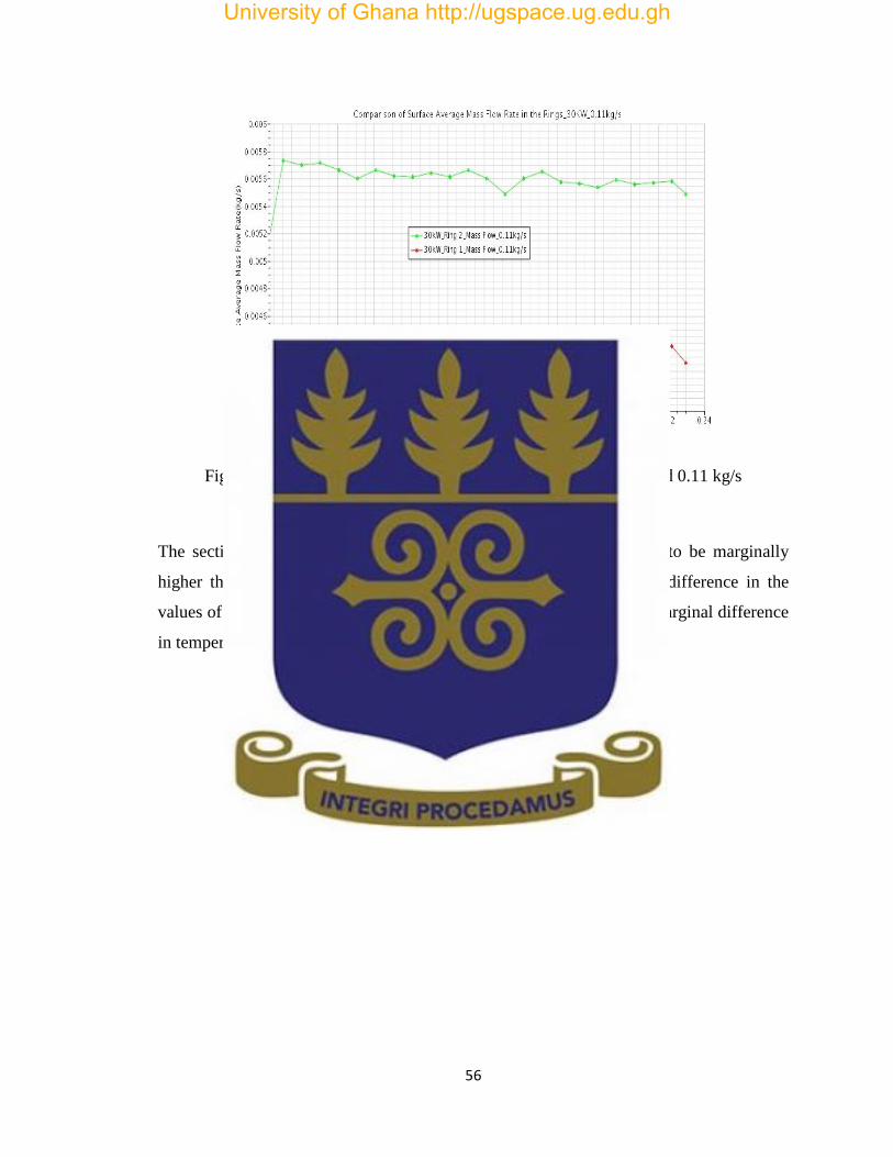
56
Figure 4.9: Comparison of Mass Flow in the 2 Rings at 30 kW and 0.11 kg/s
The sectional Average mass flow rate at 30 kW what was observed to be marginally
higher than that at 15 kW but following a similar trend. The slight difference in the
values of the coolant mass flow rate in the system is as a result of the marginal difference
in temperature between the 2 rings
University of Ghana http://ugspace.ug.edu.gh

57
Figure 4.10: Comparison of Turbulent Intensity in the 2 Rings at 30kW and 0.11kg/s
The Sectional Average turbulent intensity at 30 kW follows a similar trend to the
observations at 15 kW. Both rings were observed to have an almost similar variation at
30kW due to slight differences in the average temperature at each axial position. The
effect of increase in power on turbulent intensity significantly reduces the maximum
value at the outlet.
University of Ghana http://ugspace.ug.edu.gh

58
4.3 Analysis of Flow Parameters at Fixed Power and Varying Mass Flow Rate
4.3.1 1 Flow Parameters analysis at 30 kW and Mass Flow Rate of 0.13 kg/s
Figure 4.11: Comparison of Temperature in the 2 rings at 30 kW and 0.13 kg/s
The outlet temperature was observed to be reduced due to the increase in coolant mass
flow rate and consequently the heat transfer rate. The hottest channel in the 1st ring was
observed to be in channel 2 on the triangular pitch segment bounded by rods 3, 4 and the
control rod. The hottest channel in the 2nd ring was observed to be in channel 14a on the
triangular pitch bounded by rods 12, 13 and 4. The coldest channel in the 1st ring was
observed to be in channel 1 on the triangular pitch bounded by rods 2, 3 and the control
rod. The coldest channel in the 2nd ring was observed to be in channel 16b on the
triangular pitch segment bounded by rods 17, 18 and 6.
University of Ghana http://ugspace.ug.edu.gh

59
Figure 4.12: Comparison of Pressure in the 2 Rings at 30 kW and 0.13 kg/s
A more uniform decrease in pressure with significantly reduced spikes is observed when
the inlet mass flow rate is increased to 0.13 kg/s due to the increase in mixing as a larger
volume of coolant is available in the domain.
Figure 4.13: Comparison of Mass Flow Rate in the 2 Rings at 30 kW and 0.13 kg/s
University of Ghana http://ugspace.ug.edu.gh

60
The mass flow rate generated by the system was observed to increase slightly when the
inlet mass flow rate was increased to 0.13 kg/s at the inlet. A similar trend was observed
between the two rings.
Figure 4.14: Comparison of Turbulent Intensity in the 2 Rings at 30kW and 0.13kg/s
Increase in coolant mass flow rate resulted in a significant surge in turbulent intensity at
the inlet due to the fact that a larger volume of coolant is being introduced into the
system. The peak turbulent intensity at upper part of the fuel rods was therefore observed
to be larger than at 0.11 kg/s.
University of Ghana http://ugspace.ug.edu.gh

61
4.3.2 Flow Parameters analysis at 30kW and Mass Flow Rate of 0.15 kg/s
Figure 4.15: Comparison of Temperature in the 2 rings at 30 kW and 0.15 kg/s
Increasing the coolant mass flow rate to 0.15 kg/s further reduced the outlet temperature
as the heat transfer rate increased. The hottest channel in the 1st ring was observed to be
in channel 3 on the triangular pitch segment bounded by rods 4, 5 and the control rod.
The hottest channel in the 2nd ring was observed to be in channel 9 on the triangular pitch
bounded by rods 4, 5 and 14. The coldest channel in the 1st ring was observed to be in
channel 2 on the triangular pitch bounded by rods 3, 4 and the control rod. The coldest
channel in the 2nd ring was observed to be in channel 16b on the triangular pitch segment
bounded by rods 17, 18 and 6. Average temperature in the hottest and coldest flow
channels is in influenced by the heat generated by the rods as a result of the imposed heat
flux applied at the surface of the rods.
University of Ghana http://ugspace.ug.edu.gh

62
Figure 4.16: Comparison of Pressure in the 2 rings at 30kW and 0.15kg/s
A predominantly uniform pressure gradient was observed when the mass flow rate was
increased to 0.15 kg/s. The single spike could be attributed to an errors in computation by
the code since there is no significant drop in temperature at the same point in Figure
14.15 that could result in a corresponding increase in density and consequently an
increase in pressure at that point.
University of Ghana http://ugspace.ug.edu.gh

63
Figure 4.17: Comparison of Mass Flow Rate in the 2 rings at 30 kW and 0.15 kg/s
The Sectional Average mass flow rate generated by the system was observed to increase
significantly when the inlet mass flow rate was increased to the maximum operating
value of 0.15kg/s at the inlet. A similar trend was observed between the two rings.
University of Ghana http://ugspace.ug.edu.gh

64
Figure 4.18: Comparison of Turbulent Intensity in the 2 rings at 30 kW and 0.15 kg/s
The minimum sectional average turbulent Intensity at the inlet increased when the
coolant mass flow rate at the inlet was set to0.15 kg/s as a result of further increase in the
volume of coolant. The size of the surge at the inlet dropped significantly since the
coolant is moving at a faster rate and thus the flow develops faster in comparison to the
previous simulations. The peak turbulent intensity at upper part of the fuel rods further
increased.
University of Ghana http://ugspace.ug.edu.gh

65
4.4 Analysis of Temperature at low Mass Flow Rate
4.4.1 Temperature at 15 kW at Mass Flow Rate of 0.01 kg/s
Figure 4.19: Temperature Variation in the Hottest Channel at 15kWand 0.01kg/s
The average temperature of the hottest flow channel is 306.399 K. A maximum
temperature of 321.08 K on the axial located at 0.2222 m was computed. An outlet
Temperature of 319.47 K was computed. All calculated temperatures were below the
maximum cladding temperature at 30kW and the melting point of the U-Al alloy as
reported in the Safety Analysis Report as 313.15 K and 640 oc respectively [3]. Based on
these findings the reactor satisfies the regulatory requirements consistent with the
specifications outlined in the Safety Analysis Report and its inherent safety features
prevent structural damage together with radioactive contamination under accident
conditions.
University of Ghana http://ugspace.ug.edu.gh
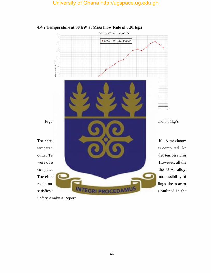
66
4.4.2 Temperature at 30 kW at Mass Flow Rate of 0.01 kg/s
Figure 4.20: Temperature Variation in the Hottest Channel at 30kWand 0.01kg/s
The sectional average temperature of the hottest flow channel is 312.45 K. A maximum
temperature of 330.68 K on the axial segment located at 0.2121 m was computed. An
outlet Temperature of 327.39 K was computed. The maximum and outlet temperatures
were observed to be above the maximum cladding temperature at 30kW. However, all the
computed temperatures were below the melting point (640 oc) of the U-Al alloy.
Therefore the integrity of the fuel is not compromised and thus there is no possibility of
radiation leakage and radioactive contamination. Based on these findings the reactor
satisfies the regulatory requirements consistent with the specifications outlined in the
Safety Analysis Report.
University of Ghana http://ugspace.ug.edu.gh

67
CHAPTER FIVE
CONCLUSION AND RECOMMENDATIONS
5.1. Conclusion
The steady state thermal hydraulic behaviour of the GHARR-1 under natural convection
cooling together with its operational safety as stipulated by the regulatory requirements
were investigated in this study.
The following conclusions were drawn under evaluation of the steady state thermal
hydraulic behaviour of GHARR-1 by numerical simulation using STAR-CCM+ CFD
code:
i. Surface Average temperature increases along the flow channel from the inlet
to the outlet in conformity with operating trends reported in the GHARR-1
Safety Analysis Report.
ii. Effective heat transfer and cooling of the reactor is achieved at the
maximum operating coolant mass flow rate of 0.15 kg/s
The following conclusions were drawn under flow channel mapping and zoning of the
GHARR-1 core:
i. The highest surface average temperature in the normal operating power
range (15-30 kW )was observed to be 296.21 K at 30 kW and coolant mass
flow rate of 0.11 kg/s
ii. The hottest flow channel is located between the inner and outer ring on the
triangular pitch distance bounded by rods 4, 5 and 14.
The following conclusions were drawn under determination of the extent to which failure
of the heat transfer will compromise safe operation of the reactor based on limits approved
by the Regulatory Authority
University of Ghana http://ugspace.ug.edu.gh

68
i. The maximum temperatures attained under normal and accident operations are
were below the melting point of the U-Al alloy fuel hence there is no possibility
of radiation leakage and radioactive contamination
ii. The Inherent safety features of the reactor enable it to operate safely during
accidents thus satisfying regulatory requirements.
The following contributions were made to current knowledge of heat generated in the
core of the GHARR-1 Miniature Neutron Source Reactor (MNSR):
i. The temperature of the hottest segment is 301.85 K located at an axial distance of
0.2020 cm. This is below the maximum cladding Temperature of 333.15 K thus
the reactor is operating safely.
ii. Results of the numerical simulation and Coolant flow channel zoning and
mapping have provided a more detailed analysis on the steady state thermal
hydraulic behaviour of the GHARR-1 under natural convection cooling
5.2. Recommendations
i. Acquisition of a high performance server to enable efficient and quick running of
simulations and modelling the entire core.
ii. Experiments to determine inlet and outlet temperatures must be performed on the
LEU core once the core conversion is completed.
iii. A similar study should be performed after the commissioning of the LEU core.
iv. Further study should cover simulation and modelling of the full geometry of the
GHARR-1 core.
v. Computational features available in CFD codes for simulation of heat transfer in
current operating Power reactors and experimental Reactor designs.
University of Ghana http://ugspace.ug.edu.gh
69
REFERENCES
[1] U.S. Department of Energy FSC-6910 Washington, D.C. 20585 (1992) DOE
Fundamentals Handbook Thermodynamics, Heat Transfer, and Fluid Flow Volume 1 of 3
[2] Kyei A.Y, Annafi T.A, Annor-Nyarko M, Quaye C.R, Bansah C. (2014) Modelling the
Velocity Profile of Coolant Flow in the GHARR-1 Fuel Channel. Journal of Nuclear
Energy Science and Power Generation Technology 2014, 3:2
http://dx.doi.org/10.4172/2325-9809.1000123
[3] Akaho, E.H.K., S. Anim-Sampong, D.N.A. Dodoo-Amoo, B.T. Maakuu, G. Emi-
Reynolds, E.K. Osae, H.O. Boadu and S. Akoto-Bamford, 2003. Final Safety Analysis
Report for Ghana Research Reactor-1, GAEC-NNRI-RT-90.
[4] Yusuf A Ahmed, Tulshi Bezboruah, Manoj Johri and E.H.K. Akaho. (2006). The low
power miniature neutron source reactors: design, safety and applications.
http://www.researchgate.net/publication/265148122
[5] S. Yamoah, E.H.K. Akaho, B.J.B. Nyarko, M. Asamoah, A.G. Ampong and E.O.
Amponsah-Abu (2011). Analysis of thermal-hydraulic transients for the Miniature Neutron
Source Reactor (MNSR) in Ghana. Research Journal of Applied Sciences, Engineering and
Technology 3(8): 737-745 ISSN:2040-7467
[6] Nuclear Regulatory Authority Act Section 23(b), 2015 (ACT 895)
[7] Nikolay Ivanov Kolev (2005) “Multiphase Flow Dynamics-Nuclear Thermal
Hydraulics” springer.com Library of Congress Control Number: 2009920195
[8] E.H.K. Akaho. (2013) Thermal Hydraulics Notes
[9] Keng-Yen Chiang. (2012) Thermal Hydraulic Limits Analysis for the MIT Research
Reactor Low Enrichment Uranium Core Conversion Using Statistical Propagation of
Parametric Uncertainties. Research Thesis submitted to the Massachusetts Institute of
Technology.
[10] Sadaf Waqar, Sikander M. Mirza, Nasir M. Mirza, Tariq Asad. (2008) A comparative
neutronic study of the standard HEU core and various potential LEU alternatives for a
typical MNSR system. Nuclear Engineering and Design 238 (2008) 2302–2307
[11] B.J.B. Nyarko, E.H.K. Akaho, Y. Serfor-Armah. (2008) The 30 kW Research Reactor
Facility in Ghana: Past, Present and Future Programmes.
https://www.researchgate.net/publication/242371685
University of Ghana http://ugspace.ug.edu.gh

70
[12] E. Ampomah-Amoako, E.H.K. Akaho, S. Anim-Sampong, B.J.B. Nyarko (2009)
Transient analysis of Ghana Research Reactor-1 using PARET/ANL thermal–hydraulic
code. Nuclear Engineering and Design 239: 2479–2483
[13] Briesmeister, J.F. (Ed.), (2000). MCNPTM—a general Monte Carlo N-particle
transport Code. Version 4c. LA-13709-M.
[14] Anim-Sampong, S., (2001). Three-dimensional Monte Carlo modeling and particle
Transport simulation of the Ghana Research Reactor-1, technical report,
NNRI/GAEC/ICTP/ENEA-TR.01/2001.
[15] C.A. Adjei, A.G. Ayensu, E.H.K. Akaho, F.K. Quashie, A.B. Asumadu-Sakyi and
E.O. Amartey. (2010) Equalisation of Transient Temperature Profile within the Fuel Pin of
a Miniature Neutron Source Reactor (MNSR) During Total Loss of Coolant. Research
Journal of Applied Sciences, Engineering and Technology 2(7): 661-668, 2010
ISSN: 2040-7467
[16] N.A. Adoo, B.J.B. Nyarko, E.H.K. Akaho, E. Alhassan, V.Y. Agbodemegbe, C.Y.
Bansah, R. Della (2010) Determination of thermal hydraulic data of GHARR-1 under
reactivity insertion transients using the PARET/ANL code. Nuclear Engineering and
Design. Journal homepage:www.elsevier.com/locate/nucengdes
[17] M. Annor-Nyarko, A.A Gyeabour, T.A. Annafi, C. R. Quaye, A. Y. Kyei. (2014)
Control Volume Finite Difference Analysis of Thermal Stresses Induced In GHARR-1
Reactor Vessel by Coolant Heating. International Journal of Scientific & Technology
Research Volume 3, Issue 8, August 2014.
[18] T. A. Annafi, A. A. Gyeabour I, E. H. K. Akaho, M. Annor-Nyarko and C. R. Quaye
(2014) Finite Difference Analysis of the Transient Temperature Profile within GHARR-1
Fuel Element. International Journal of Scientific and Technology Research. 3:8 2277-8616.
[19] S. Mohammed (2015) Investigation of Heat Transfer and Distribution in the Core of
Ghana Research Reactor-1 (GHARR-1) using STAR-CCM+ CFD Code. Thesis submitted
to the University of Ghana.
[20] H. Omar, N. Ghazi, F. Alhabit, A. Hainoun (2009) Thermal hydraulic analysis of
Syrian MNSR research reactor using RELAP5/Mod3.2 code. Annals of Nuclear Energy.
Journal homepage: www.elsevier.com/locate/anucene
[21] S.A. Agbo, Y.A. Ahmed, I.O.B. Ewa and M. Abubakar (2015) An experimental
testing of coolant flow rate and velocity in the core of Nigeria Research Reactor-1. Int. J.
Nuclear Energy Science and Technology, Vol. 9, No. 2.
University of Ghana http://ugspace.ug.edu.gh

71
[22] Harvey W. Graves Jr. (1979) Nuclear Fuel Management. John Wiley & Sons, Inc.,
New York
[23] Tong, L. S. (1967). "Heat Transfer in Water Cooled Nuclear Reactors," Nucl. Eng. and
Design, 6, Pp.301
[24] Chris Long, Nasser Sayma and bookboon.com (2009) Heat Transfer 1st Edition ISBN
978-87-7681-432-8
[25] John H. Leinhard IV and John H. Leinhard V (2008) A Heat Transfer Textbook 3rd
Edition
[26] https://en.wikipedia.org/wiki/Natural_convection 27/2/2016
[27] J. Michael Doster and Paul Turinsky (2007) NE 405/505 Reactor Systems.
www4.nscu.edu
[28] Donald Olander and Arthur Motta (2011) Light Water Reactor Materials.
http://www.mne.psu.edu/motta/Book.html
[29] Bowlesf (2010) NET 2010 Thermal Sciences
http://www.tarleton.edu/COSTWEB/tpc/Nuclear_Plant_Systems/Handouts/Thermal%20Sc
ience%20STP4.pdf
[30] In Ho Bae, Man Gyun Na, Yoon Joon Lee, Goon Cherl Pak (2008). Calculation of the
power peaking factor in a nuclear reactor using support vector regression models. Annals of
Nuclear Energy 35(12).
[31] RRRP-7225-EBEAN-002-REV0-Ch05 (e).doc. 5.8-1. 5.8 (2004) Thermal and
Hydraulic Design. 5.8.1 www.arpansa.gov.au/pubs/regulatory/opal/op/SAR/ch5e.pdf
[32] Simon Adu, Ivan Horvatovic, Francesco D’AURIA (2014). Application of Best
Estimate plus Uncertainty in Review of Research Reactor Safety Analysis. 23rd
International Conference Nuclear Energy for Europe
[33] ] Simon Adu, B.J. Benjamin Nyarko, Geoffrey Emi Reynolds, Emmanuel O. Darko,
Ivan Horvatovic, Francesco D’AURIA (2015) Analysis of Channel Blockage of the MNSR
Reactor using System thermal hydraulic Code RELAP5/MOD 3.3. 24th International
Conference Nuclear Energy for Europe
[34] Susan Maria Sipaun (2014) Thermal-fluid modeling of the Missouri S&T reactor.
Doctoral Dissertation submitted to the Missouri University of Science & Technology.
[35] Shi Shaungkai (1984) Core Thermohydraulic Calculation of Strong Neutron Source
Reactor (SNSR) CIAE Technical Report.
[36] H. C. Odoi, E. H. K. Akaho, B. J. B. Nyarko, R. G. Abrefah, E. Ampomah-Amoako,
R. B. M. Sogbadji, S. A. Birikorang, J. Gbadago J. E. Matos, J. Liaw, J. Morman, M.
Kalimullah and S. C. Mo. Current Studies of Conversion of Ghana Research Reactor Core
to Low Enriched Uranium. http://www.rertr.anl.gov/RERTR33/pdfs/S10-P2_Odoi.pdf
University of Ghana http://ugspace.ug.edu.gh

72
[37] Shuffler, Carter Alexander (2004). Optimization of hydride fueled pressurized water
reactor cores. S.M. Thesis MIT department of Nuclear Engineering
[38] Alojz Ivankovic (2009) Lecture notes for the course Computational Continuum
Mechanics (CCM) UCD School of Electrical, Electronic and Mechanical Engineering
Dublin www.ucd.ie/mecheng/ccm/CCM.pdf
[39] B. L. Smith (2013). Thermal Hydraulics Laboratory on the Use of Computational
Fluid Dynamics (CFD) in Reactor Technology. Paul Scherrer Institut
[40] Suhas V.Pantakar (1980) Numerical Heat Transfer and fluid Flow. Washington, DC,
Hemisphere Publishing Corp., 1980. 210.
[41] CD-ADAPCO (2008). CFD Basics. Americas Agency Training Document.
[42] CD-ADAPCO (2015) “User Guide STAR-CCM+, Version 10.06.009” New York.
[43] Versteeg H. K., Malalasekera, W. (2007). An Introduction to Computational Fluid
Dynamics, the Finite Volume Method. Second edition.
[44] André Bakker (2002) Lecture-10: Turbulence Models. Applied Computational Fluid
Dynamics.
[45] Markus Schatz (2004) Numerical Simulation Method. https://www.cfd.tu.-berlin.de
/research/flow control/ gurneys/node4.html
[46] J.E Bardina, P.G. Haung and T.J. Coakley (1997) Turbulence Modeling, Validation,
Testing and Development. 28th Fluid Dynamics Conference, Fluid Dynamics and Co-
located Conferences. http://dx.doi.org/10.2514/6.1997-2121
[47] Ishmael B.Celik (1999) Introductory Turbulence Modeling Lecture Notes. West
Virginia University Mechanical & Aerospace Engineering Dept.
[48] http://www.compassis.com [email protected] (2015) Turbulence Handbook
[49] The NIST Reference on Constants, Units, and Uncertainty
http://physics.nist.gov/cuu/Units/units.html
University of Ghana http://ugspace.ug.edu.gh

73
APPENDICES
Appendix I
Thermophysical Properties
Temperature
(K)
Density
(kg/m3)
Viscosity
(Pa*s)
Thermal Conductivity
(W/m*K)
274 9.9984E+02 1.7400E-03 5.6263E-01
274.5 9.9987E+02 1.7106E-03 5.6358E-01
275 9.9989E+02 1.6820E-03 5.6453E-01
275.5 9.9990E+02 1.6542E-03 5.6548E-01
276 9.9991E+02 1.6271E-03 5.6643E-01
276.5 9.9992E+02 1.6007E-03 5.6738E-01
277 9.9992E+02 1.5750E-03 5.6834E-01
277.5 9.9992E+02 1.5499E-03 5.6929E-01
278 9.9992E+02 1.5255E-03 5.7024E-01
278.5 9.9991E+02 1.5017E-03 5.7119E-01
279 9.9990E+02 1.4785E-03 5.7214E-01
279.5 9.9988E+02 1.4558E-03 5.7309E-01
280 9.9986E+02 1.4337E-03 5.7404E-01
280.5 9.9984E+02 1.4121E-03 5.7499E-01
281 9.9981E+02 1.3910E-03 5.7593E-01
281.5 9.9978E+02 1.3705E-03 5.7688E-01
282 9.9975E+02 1.3504E-03 5.7783E-01
282.5 9.9971E+02 1.3308E-03 5.7877E-01
283 9.9967E+02 1.3116E-03 5.7972E-01
283.5 9.9962E+02 1.2929E-03 5.8066E-01
284 9.9958E+02 1.2746E-03 5.8160E-01
284.5 9.9952E+02 1.2568E-03 5.8254E-01
285 9.9947E+02 1.2393E-03 5.8348E-01
285.5 9.9941E+02 1.2222E-03 5.8441E-01
286 9.9935E+02 1.2055E-03 5.8534E-01
286.5 9.9929E+02 1.1891E-03 5.8628E-01
287 9.9922E+02 1.1731E-03 5.8721E-01
287.5 9.9915E+02 1.1575E-03 5.8813E-01
288 9.9908E+02 1.1421E-03 5.8906E-01
288.5 9.9900E+02 1.1272E-03 5.8998E-01
289 9.9892E+02 1.1125E-03 5.9090E-01
289.5 9.9884E+02 1.0981E-03 5.9182E-01
290 9.9876E+02 1.0840E-03 5.9273E-01
290.5 9.9867E+02 1.0702E-03 5.9364E-01
291 9.9858E+02 1.0567E-03 5.9455E-01
291.5 9.9849E+02 1.0435E-03 5.9545E-01
292 9.9839E+02 1.0305E-03 5.9636E-01
292.5 9.9829E+02 1.0178E-03 5.9725E-01
293 9.9819E+02 1.0053E-03 5.9815E-01
293.5 9.9809E+02 9.9312E-04 5.9904E-01
University of Ghana http://ugspace.ug.edu.gh

74
294 9.9798E+02 9.8114E-04 5.9993E-01
294.5 9.9787E+02 9.6939E-04 6.0081E-01
295 9.9776E+02 9.5787E-04 6.0169E-01
295.5 9.9765E+02 9.4657E-04 6.0257E-01
296 9.9753E+02 9.3548E-04 6.0344E-01
296.5 9.9741E+02 9.2460E-04 6.0431E-01
297 9.9729E+02 9.1392E-04 6.0518E-01
297.5 9.9717E+02 9.0344E-04 6.0604E-01
298 9.9704E+02 8.9315E-04 6.0689E-01
298.5 9.9691E+02 8.8306E-04 6.0775E-01
299 9.9678E+02 8.7314E-04 6.0859E-01
299.5 9.9665E+02 8.6340E-04 6.0944E-01
300 9.9651E+02 8.5384E-04 6.1028E-01
300.5 9.9638E+02 8.4445E-04 6.1111E-01
301 9.9623E+02 8.3523E-04 6.1194E-01
301.5 9.9609E+02 8.2616E-04 6.1277E-01
302 9.9595E+02 8.1726E-04 6.1359E-01
302.5 9.9580E+02 8.0851E-04 6.1440E-01
303 9.9565E+02 7.9991E-04 6.1522E-01
303.5 9.9550E+02 7.9145E-04 6.1602E-01
304 9.9535E+02 7.8314E-04 6.1682E-01
304.5 9.9519E+02 7.7498E-04 6.1762E-01
305 9.9503E+02 7.6695E-04 6.1841E-01
305.5 9.9487E+02 7.5905E-04 6.1920E-01
306 9.9471E+02 7.5128E-04 6.1998E-01
306.5 9.9455E+02 7.4365E-04 6.2076E-01
307 9.9438E+02 7.3613E-04 6.2153E-01
307.5 9.9421E+02 7.2874E-04 6.2229E-01
308 9.9404E+02 7.2147E-04 6.2305E-01
308.5 9.9387E+02 7.1432E-04 6.2381E-01
309 9.9370E+02 7.0728E-04 6.2456E-01
309.5 9.9352E+02 7.0036E-04 6.2531E-01
310 9.9334E+02 6.9354E-04 6.2605E-01
310.5 9.9316E+02 6.8683E-04 6.2678E-01
311 9.9298E+02 6.8022E-04 6.2751E-01
311.5 9.9280E+02 6.7372E-04 6.2823E-01
312 9.9261E+02 6.6732E-04 6.2895E-01
312.5 9.9242E+02 6.6102E-04 6.2967E-01
313 9.9223E+02 6.5481E-04 6.3037E-01
313.5 9.9204E+02 6.4870E-04 6.3108E-01
314 9.9185E+02 6.4268E-04 6.3177E-01
314.5 9.9165E+02 6.3675E-04 6.3246E-01
315 9.9146E+02 6.3091E-04 6.3315E-01
315.5 9.9126E+02 6.2516E-04 6.3383E-01
316 9.9106E+02 6.1949E-04 6.3450E-01
316.5 9.9085E+02 6.1391E-04 6.3517E-01
University of Ghana http://ugspace.ug.edu.gh

75
317 9.9065E+02 6.0841E-04 6.3584E-01
317.5 9.9044E+02 6.0299E-04 6.3650E-01
318 9.9024E+02 5.9764E-04 6.3715E-01
318.5 9.9003E+02 5.9238E-04 6.3780E-01
319 9.8981E+02 5.8718E-04 6.3844E-01
319.5 9.8960E+02 5.8207E-04 6.3907E-01
320 9.8939E+02 5.7702E-04 6.3971E-01
320.5 9.8917E+02 5.7205E-04 6.4033E-01
321 9.8895E+02 5.6715E-04 6.4095E-01
321.5 9.8873E+02 5.6231E-04 6.4156E-01
322 9.8851E+02 5.5755E-04 6.4217E-01
322.5 9.8829E+02 5.5285E-04 6.4278E-01
323 9.8806E+02 5.4821E-04 6.4337E-01
323.5 9.8784E+02 5.4364E-04 6.4397E-01
324 9.8761E+02 5.3913E-04 6.4455E-01
324.5 9.8738E+02 5.3468E-04 6.4514E-01
325 9.8715E+02 5.3029E-04 6.4571E-01
325.5 9.8692E+02 5.2596E-04 6.4628E-01
326 9.8668E+02 5.2169E-04 6.4685E-01
326.5 9.8645E+02 5.1748E-04 6.4741E-01
327 9.8621E+02 5.1332E-04 6.4796E-01
327.5 9.8597E+02 5.0921E-04 6.4851E-01
328 9.8573E+02 5.0516E-04 6.4905E-01
328.5 9.8549E+02 5.0117E-04 6.4959E-01
329 9.8524E+02 4.9722E-04 6.5013E-01
329.5 9.8500E+02 4.9333E-04 6.5065E-01
330 9.8475E+02 4.8949E-04 6.5118E-01
330.5 9.8450E+02 4.8569E-04 6.5169E-01
331 9.8425E+02 4.8195E-04 6.5220E-01
331.5 9.8400E+02 4.7825E-04 6.5271E-01
332 9.8375E+02 4.7460E-04 6.5321E-01
332.5 9.8349E+02 4.7100E-04 6.5371E-01
333 9.8324E+02 4.6744E-04 6.5420E-01
333.5 9.8298E+02 4.6392E-04 6.5469E-01
334 9.8272E+02 4.6045E-04 6.5517E-01
334.5 9.8246E+02 4.5702E-04 6.5564E-01
335 9.8220E+02 4.5364E-04 6.5611E-01
335.5 9.8194E+02 4.5029E-04 6.5658E-01
336 9.8167E+02 4.4699E-04 6.5704E-01
336.5 9.8141E+02 4.4373E-04 6.5750E-01
337 9.8114E+02 4.4051E-04 6.5795E-01
337.5 9.8087E+02 4.3732E-04 6.5839E-01
338 9.8060E+02 4.3418E-04 6.5883E-01
338.5 9.8033E+02 4.3107E-04 6.5927E-01
339 9.8005E+02 4.2800E-04 6.5970E-01
339.5 9.7978E+02 4.2497E-04 6.6013E-01
University of Ghana http://ugspace.ug.edu.gh

76
340 9.7950E+02 4.2197E-04 6.6055E-01
340.5 9.7923E+02 4.1901E-04 6.6096E-01
341 9.7895E+02 4.1608E-04 6.6138E-01
341.5 9.7867E+02 4.1319E-04 6.6178E-01
342 9.7839E+02 4.1033E-04 6.6218E-01
342.5 9.7810E+02 4.0750E-04 6.6258E-01
343 9.7782E+02 4.0471E-04 6.6298E-01
343.5 9.7753E+02 4.0195E-04 6.6336E-01
344 9.7725E+02 3.9922E-04 6.6375E-01
344.5 9.7696E+02 3.9652E-04 6.6413E-01
345 9.7667E+02 3.9385E-04 6.6450E-01
345.5 9.7638E+02 3.9121E-04 6.6487E-01
346 9.7609E+02 3.8861E-04 6.6524E-01
346.5 9.7579E+02 3.8603E-04 6.6560E-01
347 9.7550E+02 3.8348E-04 6.6595E-01
347.5 9.7520E+02 3.8096E-04 6.6631E-01
348 9.7490E+02 3.7847E-04 6.6665E-01
348.5 9.7461E+02 3.7600E-04 6.6700E-01
349 9.7431E+02 3.7356E-04 6.6734E-01
349.5 9.7400E+02 3.7115E-04 6.6767E-01
350 9.7370E+02 3.6877E-04 6.6800E-01
350.5 9.7340E+02 3.6641E-04 6.6833E-01
351 9.7309E+02 3.6408E-04 6.6865E-01
351.5 9.7279E+02 3.6177E-04 6.6897E-01
352 9.7248E+02 3.5949E-04 6.6928E-01
352.5 9.7217E+02 3.5723E-04 6.6959E-01
353 9.7186E+02 3.5500E-04 6.6990E-01
353.5 9.7155E+02 3.5279E-04 6.7020E-01
354 9.7124E+02 3.5060E-04 6.7050E-01
354.5 9.7092E+02 3.4844E-04 6.7079E-01
355 9.7061E+02 3.4630E-04 6.7108E-01
355.5 9.7029E+02 3.4419E-04 6.7136E-01
356 9.6997E+02 3.4209E-04 6.7164E-01
356.5 9.6965E+02 3.4002E-04 6.7192E-01
357 9.6933E+02 3.3797E-04 6.7220E-01
357.5 9.6901E+02 3.3594E-04 6.7247E-01
358 9.6869E+02 3.3393E-04 6.7273E-01
358.5 9.6836E+02 3.3194E-04 6.7299E-01
359 9.6804E+02 3.2997E-04 6.7325E-01
359.5 9.6771E+02 3.2803E-04 6.7351E-01
360 9.6739E+02 3.2610E-04 6.7376E-01
360.5 9.6706E+02 3.2419E-04 6.7400E-01
361 9.6673E+02 3.2230E-04 6.7425E-01
361.5 9.6640E+02 3.2043E-04 6.7449E-01
362 9.6606E+02 3.1858E-04 6.7472E-01
362.5 9.6573E+02 3.1675E-04 6.7495E-01
University of Ghana http://ugspace.ug.edu.gh

77
363 9.6540E+02 3.1494E-04 6.7518E-01
363.5 9.6506E+02 3.1314E-04 6.7541E-01
364 9.6472E+02 3.1137E-04 6.7563E-01
364.5 9.6438E+02 3.0961E-04 6.7585E-01
365 9.6405E+02 3.0787E-04 6.7606E-01
365.5 9.6370E+02 3.0614E-04 6.7627E-01
366 9.6336E+02 3.0443E-04 6.7648E-01
366.5 9.6302E+02 3.0274E-04 6.7669E-01
367 9.6268E+02 3.0107E-04 6.7689E-01
367.5 9.6233E+02 2.9941E-04 6.7709E-01
368 9.6198E+02 2.9777E-04 6.7728E-01
368.5 9.6164E+02 2.9614E-04 6.7747E-01
369 9.6129E+02 2.9453E-04 6.7766E-01
369.5 9.6094E+02 2.9294E-04 6.7784E-01
370 9.6059E+02 2.9136E-04 6.7802E-01
370.5 9.6023E+02 2.8979E-04 6.7820E-01
371 9.5988E+02 2.8824E-04 6.7838E-01
371.5 9.5953E+02 2.8671E-04 6.7855E-01
372 9.5917E+02 2.8519E-04 6.7872E-01
372.5 9.5881E+02 2.8368E-04 6.7888E-01
373 9.5846E+02 2.8219E-04 6.7904E-01
373.5 9.5810E+02 2.8071E-04 6.7920E-01
374 9.5774E+02 2.7924E-04 6.7936E-01
374.5 9.5738E+02 2.7779E-04 6.7951E-01
375 9.5701E+02 2.7636E-04 6.7966E-01
375.5 9.5665E+02 2.7493E-04 6.7981E-01
376 9.5629E+02 2.7352E-04 6.7995E-01
376.5 9.5592E+02 2.7213E-04 6.8009E-01
377 9.5555E+02 2.7074E-04 6.8023E-01
377.5 9.5518E+02 2.6937E-04 6.8037E-01
378 9.5482E+02 2.6801E-04 6.8050E-01
378.5 9.5445E+02 2.6666E-04 6.8063E-01
379 9.5407E+02 2.6533E-04 6.8075E-01
379.5 9.5370E+02 2.6400E-04 6.8088E-01
380 9.5333E+02 2.6269E-04 6.8100E-01
380.5 9.5295E+02 2.6139E-04 6.8111E-01
381 9.5258E+02 2.6011E-04 6.8123E-01
381.5 9.5220E+02 2.5883E-04 6.8134E-01
382 9.5182E+02 2.5756E-04 6.8145E-01
382.5 9.5144E+02 2.5631E-04 6.8156E-01
383 9.5106E+02 2.5507E-04 6.8166E-01
383.5 9.5068E+02 2.5384E-04 6.8176E-01
384 9.5030E+02 2.5262E-04 6.8186E-01
384.5 9.4991E+02 2.5141E-04 6.8195E-01
385 9.4953E+02 2.5021E-04 6.8205E-01
385.5 9.4914E+02 2.4902E-04 6.8214E-01
University of Ghana http://ugspace.ug.edu.gh

78
386 9.4876E+02 2.4784E-04 6.8222E-01
386.5 9.4837E+02 2.4667E-04 6.8231E-01
387 9.4798E+02 2.4551E-04 6.8239E-01
387.5 9.4759E+02 2.4437E-04 6.8247E-01
388 9.4720E+02 2.4323E-04 6.8255E-01
388.5 9.4681E+02 2.4210E-04 6.8262E-01
389 9.4641E+02 2.4098E-04 6.8269E-01
389.5 9.4602E+02 2.3987E-04 6.8276E-01
390 9.4562E+02 2.3877E-04 6.8283E-01
390.5 9.4523E+02 2.3768E-04 6.8289E-01
391 9.4483E+02 2.3660E-04 6.8295E-01
391.5 9.4443E+02 2.3553E-04 6.8301E-01
392 9.4403E+02 2.3446E-04 6.8307E-01
392.5 9.4363E+02 2.3341E-04 6.8312E-01
393 9.4323E+02 2.3236E-04 6.8317E-01
393.5 9.4282E+02 2.3133E-04 6.8322E-01
394 9.4242E+02 2.3030E-04 6.8327E-01
394.5 9.4201E+02 2.2928E-04 6.8331E-01
395 9.4161E+02 2.2827E-04 6.8335E-01
395.5 9.4120E+02 2.2726E-04 6.8339E-01
396 9.4079E+02 2.2627E-04 6.8343E-01
396.5 9.4038E+02 2.2528E-04 6.8346E-01
397 9.3997E+02 2.2431E-04 6.8350E-01
397.5 9.3956E+02 2.2333E-04 6.8353E-01
398 9.3915E+02 2.2237E-04 6.8355E-01
398.5 9.3873E+02 2.2142E-04 6.8358E-01
399 9.3832E+02 2.2047E-04 6.8360E-01
399.5 9.3790E+02 2.1953E-04 6.8362E-01
400 9.3749E+02 2.1860E-04 6.8364E-01
400.5 9.3707E+02 2.1767E-04 6.8365E-01
401 9.3665E+02 2.1676E-04 6.8367E-01
401.5 9.3623E+02 2.1585E-04 6.8368E-01
402 9.3581E+02 2.1494E-04 6.8369E-01
402.5 9.3538E+02 2.1405E-04 6.8369E-01
403 9.3496E+02 2.1316E-04 6.8370E-01
403.5 9.3454E+02 2.1228E-04 6.8370E-01
404 9.3411E+02 2.1140E-04 6.8370E-01
404.5 9.3368E+02 2.1054E-04 6.8370E-01
405 9.3326E+02 2.0968E-04 6.8369E-01
405.5 9.3283E+02 2.0882E-04 6.8368E-01
406 9.3240E+02 2.0797E-04 6.8368E-01
406.5 9.3197E+02 2.0713E-04 6.8366E-01
407 9.3154E+02 2.0630E-04 6.8365E-01
407.5 9.3110E+02 2.0547E-04 6.8363E-01
408 9.3067E+02 2.0465E-04 6.8362E-01
408.5 9.3023E+02 2.0383E-04 6.8359E-01
University of Ghana http://ugspace.ug.edu.gh

79
409 9.2980E+02 2.0303E-04 6.8357E-01
409.5 9.2936E+02 2.0222E-04 6.8355E-01
410 9.2892E+02 2.0143E-04 6.8352E-01
410.5 9.2848E+02 2.0063E-04 6.8349E-01
411 9.2804E+02 1.9985E-04 6.8346E-01
411.5 9.2760E+02 1.9907E-04 6.8343E-01
412 9.2716E+02 1.9830E-04 6.8339E-01
412.5 9.2671E+02 1.9753E-04 6.8335E-01
413 9.2627E+02 1.9677E-04 6.8331E-01
413.5 9.2582E+02 1.9601E-04 6.8327E-01
414 9.2538E+02 1.9526E-04 6.8323E-01
414.5 9.2493E+02 1.9452E-04 6.8318E-01
415 9.2448E+02 1.9378E-04 6.8313E-01
415.5 9.2403E+02 1.9305E-04 6.8308E-01
416 9.2358E+02 1.9232E-04 6.8303E-01
416.5 9.2312E+02 1.9159E-04 6.8297E-01
417 9.2267E+02 1.9088E-04 6.8292E-01
417.5 9.2222E+02 1.9016E-04 6.8286E-01
418 9.2176E+02 1.8946E-04 6.8279E-01
418.5 9.2130E+02 1.8875E-04 6.8273E-01
419 9.2085E+02 1.8806E-04 6.8267E-01
419.5 9.2039E+02 1.8737E-04 6.8260E-01
420 9.1993E+02 1.8668E-04 6.8253E-01
420.5 9.1947E+02 1.8600E-04 6.8246E-01
421 9.1901E+02 1.8532E-04 6.8238E-01
421.5 9.1854E+02 1.8465E-04 6.8231E-01
422 9.1808E+02 1.8398E-04 6.8223E-01
422.5 9.1761E+02 1.8332E-04 6.8215E-01
423 9.1715E+02 1.8266E-04 6.8207E-01
423.5 9.1668E+02 1.8200E-04 6.8198E-01
424 9.1621E+02 1.8135E-04 6.8190E-01
424.5 9.1574E+02 1.8071E-04 6.8181E-01
425 9.1527E+02 1.8007E-04 6.8172E-01
425.5 9.1480E+02 1.7943E-04 6.8163E-01
426 9.1433E+02 1.7880E-04 6.8153E-01
426.5 9.1385E+02 1.7818E-04 6.8143E-01
427 9.1338E+02 1.7755E-04 6.8134E-01
427.5 9.1290E+02 1.7694E-04 6.8124E-01
428 9.1243E+02 1.7632E-04 6.8113E-01
428.5 9.1195E+02 1.7571E-04 6.8103E-01
429 9.1147E+02 1.7511E-04 6.8092E-01
429.5 9.1099E+02 1.7451E-04 6.8081E-01
430 9.1051E+02 1.7391E-04 6.8070E-01
430.5 9.1002E+02 1.7332E-04 6.8059E-01
431 9.0954E+02 1.7273E-04 6.8047E-01
431.5 9.0906E+02 1.7214E-04 6.8036E-01
University of Ghana http://ugspace.ug.edu.gh

80
432 9.0857E+02 1.7156E-04 6.8024E-01
432.5 9.0808E+02 1.7098E-04 6.8012E-01
433 9.0760E+02 1.7041E-04 6.7999E-01
433.5 9.0711E+02 1.6984E-04 6.7987E-01
434 9.0662E+02 1.6928E-04 6.7974E-01
434.5 9.0613E+02 1.6871E-04 6.7961E-01
435 9.0563E+02 1.6816E-04 6.7948E-01
435.5 9.0514E+02 1.6760E-04 6.7935E-01
436 9.0465E+02 1.6705E-04 6.7921E-01
436.5 9.0415E+02 1.6650E-04 6.7907E-01
437 9.0365E+02 1.6596E-04 6.7893E-01
437.5 9.0315E+02 1.6542E-04 6.7879E-01
438 9.0266E+02 1.6488E-04 6.7865E-01
438.5 9.0216E+02 1.6435E-04 6.7850E-01
439 9.0165E+02 1.6382E-04 6.7836E-01
439.5 9.0115E+02 1.6329E-04 6.7821E-01
440 9.0065E+02 1.6277E-04 6.7805E-01
440.5 9.0014E+02 1.6225E-04 6.7790E-01
441 8.9964E+02 1.6173E-04 6.7774E-01
441.5 8.9913E+02 1.6122E-04 6.7759E-01
442 8.9862E+02 1.6071E-04 6.7743E-01
442.5 8.9811E+02 1.6020E-04 6.7726E-01
443 8.9760E+02 1.5970E-04 6.7710E-01
University of Ghana http://ugspace.ug.edu.gh

81
Appendix II
Power Peaking Factors for the 18 Fuel Rods [12]
Segment Pin 1 Pin 2 Pin 3 Pin 4 Pin 5 Pin 6 Pin 7
1 0.39705629 0.42395157 0.41222161 0.42485287 0.41076487 0.39769118 0.38010275
2 0.87064803 0.89361208 0.85434101 0.87659279 0.87934601 0.88846863 0.89298199
3 0.94847789 0.94120446 0.95894972 0.94075929 0.95668962 0.95055308 0.93208184
4 1.00538465 0.99711814 0.98913243 0.98312602 1.02630776 1.00836388 0.97085980
5 1.08365284 1.04833353 1.03321821 1.03527970 1.05410708 1.05941491 1.03639606
6 1.07575616 1.12134869 1.10795927 1.07355770 1.09402879 1.08668686 1.12452654
7 1.10393901 1.14822342 1.15154509 1.10255556 1.17016700 1.11087001 1.17343388
8 1.17963205 1.20184959 1.18775474 1.15963353 1.18428924 1.15452432 1.16120191
9 1.21396514 1.16017459 1.18598775 1.19604180 1.20304128 1.16444140 1.19026826
10 1.21352681 1.23567586 1.23790172 1.21147902 1.18971350 1.20124005 1.17909785
11 1.23075842 1.18800130 1.20427407 1.16416059 1.23140220 1.22380687 1.20288376
12 1.18946010 1.20265775 1.17207097 1.18438513 1.20061681 1.16891367 1.18269347
13 1.17697472 1.16033896 1.15305867 1.16311273 1.17934440 1.16535229 1.14347034
14 1.13652565 1.14525788 1.14738101 1.16187309 1.15449008 1.15462020 1.08828949
15 1.13236157 1.10908932 1.09861749 1.08717998 1.10107621 1.09885720 1.07157154
16 1.06603770 1.08608417 1.03995744 1.03714943 1.04738155 1.04757331 1.04725142
17 0.99877555 0.99627573 0.99496076 1.00054939 0.95948393 0.95294332 0.94154005
18 0.95100510 0.93066414 0.92765751 0.94262216 0.88855081 0.91023414 0.91416536
19 0.81497406 0.83338365 0.82175438 0.83130847 0.86112133 0.81501515 0.79663979
20 0.75587568 0.73917143 0.75032814 0.77258677 0.76181360 0.72809691 0.74382178
21 0.65657890 0.65189706 0.65015472 0.65121834 0.63971440 0.62961446 0.64923424
Segment Pin 8 Pin 9 Pin 10 Pin 11 Pin 12 Pin 13 Pin 14
1 0.39892602 0.39768912 0.40590016 0.41260583 0.42850054 0.39499617 0.39657208
2 0.89588589 0.86082683 0.88877682 0.86127885 0.88645508 0.91337775 0.86810027
3 0.91667887 0.97642104 0.93997852 0.94311528 0.96280560 0.92106211 0.94680678
4 0.96026469 1.02315731 0.97872908 0.98478343 1.00085074 0.95145028 0.93508847
5 1.01280191 1.08280359 1.06344201 1.05453855 1.05964092 1.01271288 1.03125260
6 1.05488099 1.12803997 1.07813955 1.11779416 1.09991876 1.04076560 1.08399528
7 1.15842814 1.14115544 1.13696397 1.18076211 1.11555460 1.10918520 1.15336687
8 1.16135258 1.15967462 1.15681182 1.16282508 1.17152991 1.13869672 1.16073619
9 1.18875467 1.16714668 1.23874413 1.25063366 1.21194474 1.22105365 1.16558515
10 1.20749986 1.22675871 1.20836281 1.21928666 1.22085504 1.17335855 1.19743896
11 1.18678906 1.21579377 1.17336539 1.23518959 1.20132908 1.20034970 1.15905823
12 1.21009556 1.25626338 1.17094776 1.18878206 1.19336392 1.17891293 1.21136944
13 1.19711706 1.20617119 1.16492766 1.15230531 1.15468869 1.16142792 1.15259296
14 1.15368877 1.11890366 1.06690065 1.11480807 1.14929183 1.07826968 1.13097126
15 1.10676072 1.09495338 1.06409264 1.05964092 1.06664040 1.11945842 1.04414206
University of Ghana http://ugspace.ug.edu.gh

82
Segment Pin 15 Pin 16 Pin 17 Pin 18
1 0.42481315 0.41372424 0.40603987 0.40701035
2 0.85445059 0.86986041 0.90851509 0.90013900
3 0.98224937 0.95006682 0.92482211 0.95044350
4 1.01054180 0.99346087 1.00609008 0.99970014
5 1.07457817 1.05268938 1.07923536 1.07610545
6 1.11142476 1.10254871 1.11394513 1.13099181
7 1.16787265 1.14286765 1.09804219 1.16800963
8 1.16109918 1.19267219 1.14209373 1.20182220
9 1.17264627 1.26281769 1.18779584 1.18826840
10 1.16268125 1.15328469 1.20902714 1.17897457
11 1.17250244 1.21651974 1.21016405 1.21751282
12 1.21899216 1.17173538 1.21656083 1.17904991
13 1.15707893 1.13334780 1.17325581 1.14832615
14 1.14921649 1.11428757 1.12651269 1.14621671
15 1.09983658 1.07637256
1.02687621 1.14638109
16 0.98866671 1.02906098
1.03786855
1.01021306
17 0.97667444 0.97906468 0.95039556 0.96153172
18 0.92089089 0.91396674 0.87705166 0.90706314
19 0.81507679 0.76818984 0.83592456 0.86360745
20 0.71294050 0.71781685 0.72813800 0.76323130
21 0.61880772 0.64739397 0.61181851 0.68665477
16 1.00239857 1.03445100 1.07652323 1.02002056 1.05500427 1.02030821 0.99439916
17 0.97722235 0.97712646 0.97047627 0.96273711 1.00094662 0.94277284 0.98551625
18 0.90790555 0.91572004 0.92419202 0.88314710 0.87650376 0.88323614 0.89879663
19 0.85420403 0.84604025 0.80217363 0.80672809 0.78780483 0.81020044 0.84931398
20 0.75130752 0.77560710 0.71695390 0.76186154 0.69920863 0.77562080 0.73416496
21 0.66813011 0.64618173 0.65757061 0.70881751 0.63939798 0.64229982 0.65697751
University of Ghana http://ugspace.ug.edu.gh

83
Appendix III
Heat Fluxes for Fuel Rods
Rod 1
Segments
Heat flux
5kW
Heat Flux
10kW
Heat Flux
15kW
Heat Flux
20kW
Heat Flux
25kW
Heat Flux
30kW
1 1.187E+05 4.272E+06 3.560E+05 4.747E+05 5.934E+05 7.120E+05
2 2.602E+05 9.368E+06 7.807E+05 1.041E+06 1.301E+06 1.561E+06
3 2.835E+05 1.021E+07 8.505E+05 1.134E+06 1.417E+06 1.701E+06
4 3.005E+05 1.082E+07 9.015E+05 1.202E+06 1.502E+06 1.803E+06
5 3.239E+05 1.166E+07 9.717E+05 1.296E+06 1.619E+06 1.943E+06
6 3.215E+05 1.157E+07 9.646E+05 1.286E+06 1.608E+06 1.929E+06
7 3.299E+05 1.188E+07 9.898E+05 1.320E+06 1.650E+06 1.980E+06
8 3.526E+05 1.269E+07 1.058E+06 1.410E+06 1.763E+06 2.115E+06
9 3.628E+05 1.306E+07 1.088E+06 1.451E+06 1.814E+06 2.177E+06
10 3.627E+05 1.306E+07 1.088E+06 1.451E+06 1.814E+06 2.176E+06
11 3.679E+05 1.324E+07 1.104E+06 1.471E+06 1.839E+06 2.207E+06
12 3.555E+05 1.280E+07 1.067E+06 1.422E+06 1.778E+06 2.133E+06
13 3.518E+05 1.266E+07 1.055E+06 1.407E+06 1.759E+06 2.111E+06
14 3.397E+05 1.223E+07 1.019E+06 1.359E+06 1.698E+06 2.038E+06
15 3.384E+05 1.218E+07 1.015E+06 1.354E+06 1.692E+06 2.031E+06
16 3.186E+05 1.147E+07 9.559E+05 1.274E+06 1.593E+06 1.912E+06
17 2.985E+05 1.075E+07 8.955E+05 1.194E+06 1.493E+06 1.791E+06
18 2.842E+05 1.023E+07 8.527E+05 1.137E+06 1.421E+06 1.705E+06
19 2.436E+05 8.769E+06 7.307E+05 9.743E+05 1.218E+06 1.461E+06
20 2.259E+05 8.133E+06 6.778E+05 9.037E+05 1.130E+06 1.356E+06
21 1.962E+05 7.065E+06 5.887E+05 7.850E+05 9.812E+05 1.177E+06
Rod 2
Segments
Heat flux
5kW
Heat Flux
10kW
Heat Flux
15kW
Heat Flux
20kW
Heat Flux
25kW
Heat Flux
30kW
1 1.266E+05 2.533E+05 3.799E+05 5.065E+05 6.332E+05 7.598E+05
2 2.669E+05 5.338E+05 8.008E+05 1.068E+06 1.335E+06 1.602E+06
3 2.811E+05 5.623E+05 8.434E+05 1.125E+06 1.406E+06 1.687E+06
4 2.978E+05 5.957E+05 8.935E+05 1.191E+06 1.489E+06 1.787E+06
5 3.131E+05 6.263E+05 9.394E+05 1.253E+06 1.566E+06 1.879E+06
6 3.349E+05 6.699E+05 1.005E+06 1.340E+06 1.675E+06 2.010E+06
7 3.430E+05 6.859E+05 1.029E+06 1.372E+06 1.715E+06 2.058E+06
8 3.590E+05 7.180E+05 1.077E+06 1.436E+06 1.795E+06 2.154E+06
9 3.465E+05 6.931E+05 1.040E+06 1.386E+06 1.733E+06 2.079E+06
10 3.691E+05 7.382E+05 1.107E+06 1.476E+06 1.845E+06 2.215E+06
11 3.549E+05 7.097E+05 1.065E+06 1.419E+06 1.774E+06 2.129E+06
12 3.592E+05 7.185E+05 1.078E+06 1.437E+06 1.796E+06 2.155E+06
13 3.466E+05 6.932E+05 1.040E+06 1.386E+06 1.733E+06 2.080E+06
14 3.421E+05 6.842E+05 1.026E+06 1.368E+06 1.710E+06 2.053E+06
15 3.313E+05 6.626E+05 9.939E+05 1.325E+06 1.656E+06 1.988E+06
16 3.244E+05 6.488E+05 9.732E+05 1.298E+06 1.622E+06 1.946E+06
17 2.976E+05 5.952E+05 8.928E+05 1.190E+06 1.488E+06 1.786E+06
18 2.780E+05 5.560E+05 8.340E+05 1.112E+06 1.390E+06 1.668E+06
University of Ghana http://ugspace.ug.edu.gh

84
19 2.489E+05 4.979E+05 7.468E+05 9.957E+05 1.245E+06 1.494E+06
20 2.208E+05 4.416E+05 6.624E+05 8.832E+05 1.104E+06 1.325E+06
21 1.947E+05 3.894E+05 5.842E+05 7.789E+05 9.736E+05 1.168E+06
Rod 3
Segments
Heat flux
5kW
Heat Flux
10kW
Heat Flux
15kW
Heat Flux
20kW
Heat Flux
25kW
Heat Flux
30kW
1 1.239E+05 2.478E+05 3.718E+05 4.957E+05 6.196E+05 7.435E+05
2 2.568E+05 5.137E+05 7.705E+05 1.027E+06 1.284E+06 1.541E+06
3 2.883E+05 5.765E+05 8.648E+05 1.153E+06 1.441E+06 1.730E+06
4 2.973E+05 5.947E+05 8.920E+05 1.189E+06 1.487E+06 1.784E+06
5 3.106E+05 6.212E+05 9.318E+05 1.242E+06 1.553E+06 1.864E+06
6 3.331E+05 6.661E+05 9.992E+05 1.332E+06 1.665E+06 1.998E+06
7 3.462E+05 6.923E+05 1.039E+06 1.385E+06 1.731E+06 2.077E+06
8 3.571E+05 7.141E+05 1.071E+06 1.428E+06 1.785E+06 2.142E+06
9 3.565E+05 7.131E+05 1.070E+06 1.426E+06 1.783E+06 2.139E+06
10 3.721E+05 7.443E+05 1.116E+06 1.489E+06 1.861E+06 2.233E+06
11 3.620E+05 7.240E+05 1.086E+06 1.448E+06 1.810E+06 2.172E+06
12 3.523E+05 7.047E+05 1.057E+06 1.409E+06 1.762E+06 2.114E+06
13 3.466E+05 6.933E+05 1.040E+06 1.387E+06 1.733E+06 2.080E+06
14 3.449E+05 6.898E+05 1.035E+06 1.380E+06 1.725E+06 2.070E+06
15 3.303E+05 6.605E+05 9.908E+05 1.321E+06 1.651E+06 1.982E+06
16 3.126E+05 6.253E+05 9.379E+05 1.251E+06 1.563E+06 1.876E+06
17 2.991E+05 5.982E+05 8.973E+05 1.196E+06 1.495E+06 1.795E+06
18 2.789E+05 5.577E+05 8.366E+05 1.115E+06 1.394E+06 1.673E+06
19 2.470E+05 4.941E+05 7.411E+05 9.881E+05 1.235E+06 1.482E+06
20 2.256E+05 4.511E+05 6.767E+05 9.022E+05 1.128E+06 1.353E+06
21 1.954E+05 3.909E+05 5.863E+05 7.818E+05 9.772E+05 1.173E+06
Rod 4
Segments
Heat flux
5kW
Heat Flux
10kW
Heat Flux
15kW
Heat Flux
20kW
Heat Flux
25kW
Heat Flux
30kW
1 1.282E+05 2.564E+05 3.846E+05 5.128E+05 6.410E+05 7.692E+05
2 2.645E+05 5.290E+05 7.935E+05 1.058E+06 1.323E+06 1.587E+06
3 2.839E+05 5.677E+05 8.516E+05 1.135E+06 1.419E+06 1.703E+06
4 2.967E+05 5.933E+05 8.900E+05 1.187E+06 1.483E+06 1.780E+06
5 3.124E+05 6.248E+05 9.372E+05 1.250E+06 1.562E+06 1.874E+06
6 3.239E+05 6.479E+05 9.718E+05 1.296E+06 1.620E+06 1.944E+06
7 3.327E+05 6.654E+05 9.981E+05 1.331E+06 1.663E+06 1.996E+06
8 3.499E+05 6.998E+05 1.050E+06 1.400E+06 1.750E+06 2.100E+06
9 3.609E+05 7.218E+05 1.083E+06 1.444E+06 1.805E+06 2.165E+06
10 3.656E+05 7.311E+05 1.097E+06 1.462E+06 1.828E+06 2.193E+06
11 3.513E+05 7.026E+05 1.054E+06 1.405E+06 1.756E+06 2.108E+06
12 3.574E+05 7.148E+05 1.072E+06 1.430E+06 1.787E+06 2.144E+06
13 3.510E+05 7.019E+05 1.053E+06 1.404E+06 1.755E+06 2.106E+06
14 3.506E+05 7.012E+05 1.052E+06 1.402E+06 1.753E+06 2.104E+06
15 3.281E+05 6.561E+05 9.842E+05 1.312E+06 1.640E+06 1.968E+06
16 3.130E+05 6.259E+05 9.389E+05 1.252E+06 1.565E+06 1.878E+06
17 3.019E+05 6.038E+05 9.057E+05 1.208E+06 1.510E+06 1.811E+06
18 2.844E+05 5.689E+05 8.533E+05 1.138E+06 1.422E+06 1.707E+06
University of Ghana http://ugspace.ug.edu.gh

85
19 2.508E+05 5.017E+05 7.525E+05 1.003E+06 1.254E+06 1.505E+06
20 2.331E+05 4.663E+05 6.994E+05 9.325E+05 1.166E+06 1.399E+06
21 1.965E+05 3.930E+05 5.895E+05 7.860E+05 9.825E+05 1.179E+06
Rod 5
Segments
Heat flux
5kW
Heat Flux
10kW
Heat Flux
15kW
Heat Flux
20kW
Heat Flux
25kW
Heat Flux
30kW
1 1.228E+05 2.456E+05 3.684E+05 4.913E+05 6.141E+05 1.578E+06
2 2.629E+05 5.258E+05 7.888E+05 1.052E+06 1.315E+06 1.716E+06
3 2.860E+05 5.721E+05 8.581E+05 1.144E+06 1.430E+06 1.841E+06
4 3.069E+05 6.137E+05 9.206E+05 1.227E+06 1.534E+06 1.891E+06
5 3.152E+05 6.303E+05 9.455E+05 1.261E+06 1.576E+06 1.963E+06
6 3.271E+05 6.542E+05 9.813E+05 1.308E+06 1.636E+06 2.099E+06
7 3.499E+05 6.997E+05 1.050E+06 1.399E+06 1.749E+06 2.125E+06
8 3.541E+05 7.082E+05 1.062E+06 1.416E+06 1.770E+06 2.158E+06
9 3.597E+05 7.194E+05 1.079E+06 1.439E+06 1.799E+06 2.134E+06
10 3.557E+05 7.114E+05 1.067E+06 1.423E+06 1.779E+06 2.209E+06
11 3.682E+05 7.364E+05 1.105E+06 1.473E+06 1.841E+06 2.154E+06
12 3.590E+05 7.180E+05 1.077E+06 1.436E+06 1.795E+06 2.116E+06
13 3.526E+05 7.052E+05 1.058E+06 1.410E+06 1.763E+06 2.071E+06
14 3.452E+05 6.904E+05 1.036E+06 1.381E+06 1.726E+06 1.975E+06
15 3.292E+05 6.584E+05 9.876E+05 1.317E+06 1.646E+06 1.879E+06
16 3.132E+05 6.263E+05 9.395E+05 1.253E+06 1.566E+06 1.721E+06
17 2.869E+05 5.738E+05 8.606E+05 1.148E+06 1.434E+06 1.594E+06
18 2.657E+05 5.313E+05 7.970E+05 1.063E+06 1.328E+06 1.545E+06
19 2.575E+05 5.149E+05 7.724E+05 1.030E+06 1.287E+06 1.367E+06
20 2.278E+05 4.556E+05 6.833E+05 9.111E+05 1.139E+06 1.148E+06
21 1.913E+05 3.825E+05 5.738E+05 7.651E+05 9.564E+05 3.802E+07
Rod 6
Segments
Heat flux
5kW
Heat Flux
10kW
Heat Flux
15kW
Heat Flux
20kW
Heat Flux
25kW
Heat Flux
30kW
1 1.205E+05 2.410E+05 3.614E+05 4.819E+05 6.024E+05 7.229E+05
2 2.692E+05 5.383E+05 8.075E+05 1.077E+06 1.346E+06 1.615E+06
3 2.880E+05 5.759E+05 8.639E+05 1.152E+06 1.440E+06 1.728E+06
4 3.055E+05 6.110E+05 9.164E+05 1.222E+06 1.527E+06 1.833E+06
5 3.209E+05 6.419E+05 9.628E+05 1.284E+06 1.605E+06 1.926E+06
6 3.292E+05 6.584E+05 9.876E+05 1.317E+06 1.646E+06 1.975E+06
7 3.365E+05 6.731E+05 1.010E+06 1.346E+06 1.683E+06 2.019E+06
8 3.498E+05 6.995E+05 1.049E+06 1.399E+06 1.749E+06 2.099E+06
9 3.528E+05 7.055E+05 1.058E+06 1.411E+06 1.764E+06 2.117E+06
10 3.639E+05 7.278E+05 1.092E+06 1.456E+06 1.820E+06 2.183E+06
11 3.707E+05 7.415E+05 1.112E+06 1.483E+06 1.854E+06 2.224E+06
12 3.541E+05 7.082E+05 1.062E+06 1.416E+06 1.771E+06 2.125E+06
13 3.530E+05 7.061E+05 1.059E+06 1.412E+06 1.765E+06 2.118E+06
14 3.498E+05 6.996E+05 1.049E+06 1.399E+06 1.749E+06 2.099E+06
15 3.329E+05 6.658E+05 9.987E+05 1.332E+06 1.664E+06 1.997E+06
16 3.174E+05 6.347E+05 9.521E+05 1.269E+06 1.587E+06 1.904E+06
17 2.887E+05 5.774E+05 8.661E+05 1.155E+06 1.443E+06 1.732E+06
18 2.757E+05 5.515E+05 8.272E+05 1.103E+06 1.379E+06 1.654E+06
University of Ghana http://ugspace.ug.edu.gh

86
19 2.469E+05 4.938E+05 7.407E+05 9.876E+05 1.235E+06 1.481E+06
20 2.206E+05 4.411E+05 6.617E+05 8.823E+05 1.103E+06 1.323E+06
21 1.907E+05 3.815E+05 5.722E+05 7.629E+05 9.537E+05 1.144E+06
Rod 7
Segments
Heat flux
5kW
Heat Flux
10kW
Heat Flux
15kW
Heat Flux
20kW
Heat Flux
25kW
Heat Flux
30kW
1 5.205E+05 1.157E+05 1.735E+05 2.313E+05 2.892E+05 3.470E+05
2 1.223E+06 2.718E+05 4.076E+05 5.435E+05 6.794E+05 8.153E+05
3 1.276E+06 2.837E+05 4.255E+05 5.673E+05 7.091E+05 8.510E+05
4 1.330E+06 2.955E+05 4.432E+05 5.909E+05 7.386E+05 8.864E+05
5 1.419E+06 3.154E+05 4.731E+05 6.308E+05 7.885E+05 9.462E+05
6 1.540E+06 3.422E+05 5.133E+05 6.844E+05 8.555E+05 1.027E+06
7 1.607E+06 3.571E+05 5.357E+05 7.142E+05 8.928E+05 1.071E+06
8 1.590E+06 3.534E+05 5.301E+05 7.068E+05 8.834E+05 1.060E+06
9 1.630E+06 3.622E+05 5.433E+05 7.244E+05 9.056E+05 1.087E+06
10 1.615E+06 3.588E+05 5.382E+05 7.176E+05 8.971E+05 1.076E+06
11 1.647E+06 3.661E+05 5.491E+05 7.321E+05 9.152E+05 1.098E+06
12 1.620E+06 3.599E+05 5.399E+05 7.198E+05 8.998E+05 1.080E+06
13 1.566E+06 3.480E+05 5.220E+05 6.960E+05 8.700E+05 1.044E+06
14 1.490E+06 3.312E+05 4.968E+05 6.624E+05 8.280E+05 9.936E+05
15 1.467E+06 3.261E+05 4.892E+05 6.522E+05 8.153E+05 9.783E+05
16 1.434E+06 3.187E+05 4.781E+05 6.374E+05 7.968E+05 9.561E+05
17 1.289E+06 2.865E+05 4.298E+05 5.731E+05 7.163E+05 8.596E+05
18 1.252E+06 2.782E+05 4.173E+05 5.564E+05 6.955E+05 8.346E+05
19 1.091E+06 2.424E+05 3.637E+05 4.849E+05 6.061E+05 7.273E+05
20 1.019E+06 2.264E+05 3.395E+05 4.527E+05 5.659E+05 6.791E+05
21 8.891E+05 1.976E+05 2.964E+05 3.952E+05 4.939E+05 5.927E+05
Rod 8
Segments
Heat flux
5kW
Heat Flux
10kW
Heat Flux
15kW
Heat Flux
20kW
Heat Flux
25kW
Heat Flux
30kW
1 6.027E+04 1.205E+05 1.808E+05 2.411E+05 3.014E+05 3.616E+05
2 1.354E+05 2.707E+05 4.061E+05 5.414E+05 6.768E+05 8.121E+05
3 1.385E+05 2.770E+05 4.155E+05 5.540E+05 6.925E+05 8.310E+05
4 1.451E+05 2.902E+05 4.352E+05 5.803E+05 7.254E+05 8.705E+05
5 1.530E+05 3.060E+05 4.590E+05 6.121E+05 7.651E+05 9.181E+05
6 1.594E+05 3.187E+05 4.781E+05 6.375E+05 7.969E+05 9.562E+05
7 1.750E+05 3.500E+05 5.251E+05 7.001E+05 8.751E+05 1.050E+06
8 1.755E+05 3.509E+05 5.264E+05 7.018E+05 8.773E+05 1.053E+06
9 1.796E+05 3.592E+05 5.388E+05 7.184E+05 8.980E+05 1.078E+06
10 1.824E+05 3.649E+05 5.473E+05 7.297E+05 9.122E+05 1.095E+06
11 1.793E+05 3.586E+05 5.379E+05 7.172E+05 8.965E+05 1.076E+06
12 1.828E+05 3.656E+05 5.485E+05 7.313E+05 9.141E+05 1.097E+06
13 1.809E+05 3.617E+05 5.426E+05 7.235E+05 9.043E+05 1.085E+06
14 1.743E+05 3.486E+05 5.229E+05 6.972E+05 8.715E+05 1.046E+06
15 1.672E+05 3.344E+05 5.016E+05 6.688E+05 8.361E+05 1.003E+06
16 1.514E+05 3.029E+05 4.543E+05 6.058E+05 7.572E+05 9.087E+05
17 1.476E+05 2.953E+05 4.429E+05 5.906E+05 7.382E+05 8.858E+05
18 1.372E+05 2.743E+05 4.115E+05 5.487E+05 6.858E+05 8.230E+05
University of Ghana http://ugspace.ug.edu.gh

87
19 1.291E+05 2.581E+05 3.872E+05 5.162E+05 6.453E+05 7.743E+05
20 1.135E+05 2.270E+05 3.405E+05 4.540E+05 5.675E+05 6.811E+05
21 1.009E+05 2.019E+05 3.028E+05 4.038E+05 5.047E+05 6.057E+05
Rod 9
Segments
Heat flux
5kW
Heat Flux
10kW
Heat Flux
15kW
Heat Flux
20kW
Heat Flux
25kW
Heat Flux
30kW
1 5.929E+04 1.186E+05 1.779E+05 2.372E+05 2.965E+05 3.558E+05
2 1.283E+05 2.567E+05 3.850E+05 5.134E+05 6.417E+05 7.701E+05
3 1.456E+05 2.912E+05 4.367E+05 5.823E+05 7.279E+05 8.735E+05
4 1.525E+05 3.051E+05 4.576E+05 6.102E+05 7.627E+05 9.153E+05
5 1.614E+05 3.229E+05 4.843E+05 6.458E+05 8.072E+05 9.686E+05
6 1.682E+05 3.364E+05 5.045E+05 6.727E+05 8.409E+05 1.009E+06
7 1.701E+05 3.403E+05 5.104E+05 6.806E+05 8.507E+05 1.021E+06
8 1.729E+05 3.458E+05 5.187E+05 6.916E+05 8.645E+05 1.037E+06
9 1.740E+05 3.480E+05 5.220E+05 6.961E+05 8.701E+05 1.044E+06
10 1.829E+05 3.658E+05 5.487E+05 7.316E+05 9.145E+05 1.097E+06
11 1.813E+05 3.625E+05 5.438E+05 7.251E+05 9.063E+05 1.088E+06
12 1.873E+05 3.746E+05 5.619E+05 7.492E+05 9.365E+05 1.124E+06
13 1.798E+05 3.597E+05 5.395E+05 7.193E+05 8.992E+05 1.079E+06
14 1.668E+05 3.336E+05 5.005E+05 6.673E+05 8.341E+05 1.001E+06
15 1.632E+05 3.265E+05 4.897E+05 6.530E+05 8.162E+05 9.795E+05
16 1.542E+05 3.085E+05 4.627E+05 6.169E+05 7.711E+05 9.254E+05
17 1.457E+05 2.914E+05 4.370E+05 5.827E+05 7.284E+05 8.741E+05
18 1.365E+05 2.731E+05 4.096E+05 5.461E+05 6.826E+05 8.192E+05
19 1.261E+05 2.523E+05 3.784E+05 5.046E+05 6.307E+05 7.568E+05
20 1.156E+05 2.313E+05 3.469E+05 4.626E+05 5.782E+05 6.938E+05
21 9.634E+04 1.927E+05 2.890E+05 3.854E+05 4.817E+05 5.780E+05
Rod 10
Segments
Heat flux
5kW
Heat Flux
10kW
Heat Flux
15kW
Heat Flux
20kW
Heat Flux
25kW
Heat Flux
30kW
1 6.158E+04 1.232E+05 1.847E+05 2.463E+05 3.079E+05 3.695E+05
2 1.348E+05 2.697E+05 4.045E+05 5.394E+05 6.742E+05 8.090E+05
3 1.426E+05 2.852E+05 4.278E+05 5.704E+05 7.130E+05 8.556E+05
4 1.485E+05 2.970E+05 4.455E+05 5.939E+05 7.424E+05 8.909E+05
5 1.613E+05 3.227E+05 4.840E+05 6.453E+05 8.067E+05 9.680E+05
6 1.636E+05 3.271E+05 4.907E+05 6.543E+05 8.178E+05 9.814E+05
7 1.725E+05 3.450E+05 5.175E+05 6.900E+05 8.625E+05 1.035E+06
8 1.755E+05 3.510E+05 5.265E+05 7.020E+05 8.775E+05 1.053E+06
9 1.879E+05 3.759E+05 5.638E+05 7.517E+05 9.397E+05 1.128E+06
10 1.833E+05 3.666E+05 5.500E+05 7.333E+05 9.166E+05 1.100E+06
11 1.780E+05 3.560E+05 5.340E+05 7.121E+05 8.901E+05 1.068E+06
12 1.776E+05 3.553E+05 5.329E+05 7.106E+05 8.882E+05 1.066E+06
13 1.767E+05 3.535E+05 5.302E+05 7.069E+05 8.837E+05 1.060E+06
14 1.619E+05 3.237E+05 4.856E+05 6.474E+05 8.093E+05 9.712E+05
15 1.614E+05 3.229E+05 4.843E+05 6.457E+05 8.072E+05 9.686E+05
16 1.633E+05 3.266E+05 4.900E+05 6.533E+05 8.166E+05 9.799E+05
17 1.472E+05 2.945E+05 4.417E+05 5.889E+05 7.362E+05 8.834E+05
18 1.402E+05 2.804E+05 4.206E+05 5.608E+05 7.011E+05 8.413E+05
University of Ghana http://ugspace.ug.edu.gh

88
19 1.217E+05 2.434E+05 3.651E+05 4.868E+05 6.085E+05 7.302E+05
20 1.088E+05 2.175E+05 3.263E+05 4.351E+05 5.439E+05 6.526E+05
21 9.976E+04 1.995E+05 2.993E+05 3.990E+05 4.988E+05 5.986E+05
Rod 11
Segments
Heat flux
5kW
Heat Flux
10kW
Heat Flux
15kW
Heat Flux
20kW
Heat Flux
25kW
Heat Flux
30kW
1 6.201E+04 1.240E+05 1.860E+05 2.480E+05 3.101E+05 3.721E+05
2 1.294E+05 2.589E+05 3.883E+05 5.178E+05 6.472E+05 7.766E+05
3 1.417E+05 2.835E+05 4.252E+05 5.670E+05 7.087E+05 8.504E+05
4 1.480E+05 2.960E+05 4.440E+05 5.920E+05 7.400E+05 8.880E+05
5 1.585E+05 3.170E+05 4.755E+05 6.339E+05 7.924E+05 9.509E+05
6 1.680E+05 3.360E+05 5.040E+05 6.720E+05 8.400E+05 1.008E+06
7 1.775E+05 3.549E+05 5.324E+05 7.098E+05 8.873E+05 1.065E+06
8 1.748E+05 3.495E+05 5.243E+05 6.990E+05 8.738E+05 1.049E+06
9 1.880E+05 3.759E+05 5.639E+05 7.518E+05 9.398E+05 1.128E+06
10 1.832E+05 3.665E+05 5.497E+05 7.330E+05 9.162E+05 1.099E+06
11 1.856E+05 3.713E+05 5.569E+05 7.425E+05 9.282E+05 1.114E+06
12 1.787E+05 3.573E+05 5.360E+05 7.146E+05 8.933E+05 1.072E+06
13 1.732E+05 3.464E+05 5.195E+05 6.927E+05 8.659E+05 1.039E+06
14 1.675E+05 3.351E+05 5.026E+05 6.702E+05 8.377E+05 1.005E+06
15 1.593E+05 3.185E+05 4.778E+05 6.370E+05 7.963E+05 9.555E+05
16 1.533E+05 3.066E+05 4.599E+05 6.132E+05 7.665E+05 9.198E+05
17 1.447E+05 2.894E+05 4.341E+05 5.788E+05 7.234E+05 8.681E+05
18 1.327E+05 2.655E+05 3.982E+05 5.309E+05 6.636E+05 7.964E+05
19 1.212E+05 2.425E+05 3.637E+05 4.850E+05 6.062E+05 7.275E+05
20 1.145E+05 2.290E+05 3.435E+05 4.580E+05 5.725E+05 6.870E+05
21 1.065E+05 2.131E+05 3.196E+05 4.261E+05 5.326E+05 6.392E+05
Rod 12
Segments
Heat flux
5kW
Heat Flux
10kW
Heat Flux
15kW
Heat Flux
20kW
Heat Flux
25kW
Heat Flux
30kW
1 6.470E+04 1.294E+05 1.941E+05 9.317E+06 3.235E+05 3.882E+05
2 1.339E+05 2.677E+05 4.016E+05 1.928E+07 6.693E+05 8.031E+05
3 1.454E+05 2.908E+05 4.362E+05 2.094E+07 7.269E+05 8.723E+05
4 1.511E+05 3.023E+05 4.534E+05 2.176E+07 7.557E+05 9.068E+05
5 1.600E+05 3.200E+05 4.800E+05 2.304E+07 8.000E+05 9.600E+05
6 1.661E+05 3.322E+05 4.983E+05 2.392E+07 8.304E+05 9.965E+05
7 1.685E+05 3.369E+05 5.054E+05 2.426E+07 8.423E+05 1.011E+06
8 1.769E+05 3.538E+05 5.307E+05 2.547E+07 8.845E+05 1.061E+06
9 1.830E+05 3.660E+05 5.490E+05 2.635E+07 9.150E+05 1.098E+06
10 1.844E+05 3.687E+05 5.531E+05 2.655E+07 9.218E+05 1.106E+06
11 1.814E+05 3.628E+05 5.442E+05 2.612E+07 9.070E+05 1.088E+06
12 1.802E+05 3.604E+05 5.406E+05 2.595E+07 9.010E+05 1.081E+06
13 1.744E+05 3.487E+05 5.231E+05 2.511E+07 8.718E+05 1.046E+06
14 1.735E+05 3.471E+05 5.206E+05 2.499E+07 8.677E+05 1.041E+06
15 1.611E+05 3.221E+05 4.832E+05 2.319E+07 8.053E+05 9.664E+05
16 1.593E+05 3.186E+05 4.779E+05 2.294E+07 7.965E+05 9.558E+05
17 1.511E+05 3.023E+05 4.534E+05 2.176E+07 7.557E+05 9.069E+05
18 1.324E+05 2.647E+05 3.971E+05 1.906E+07 6.618E+05 7.941E+05
University of Ghana http://ugspace.ug.edu.gh

89
19 1.190E+05 2.379E+05 3.569E+05 1.713E+07 5.948E+05 7.138E+05
20 1.056E+05 2.112E+05 3.167E+05 1.520E+07 5.279E+05 6.335E+05
21 9.655E+04 1.931E+05 2.897E+05 1.390E+07 4.828E+05 5.793E+05
Rod 13
Segments
Heat flux
5kW
Heat Flux
10kW
Heat Flux
15kW
Heat Flux
20kW
Heat Flux
25kW
Heat Flux
30kW
1 6.049E+04 1.210E+05 1.815E+05 2.420E+05 3.024E+05 3.629E+05
2 1.399E+05 2.797E+05 4.196E+05 5.595E+05 6.994E+05 8.392E+05
3 1.410E+05 2.821E+05 4.231E+05 5.642E+05 7.052E+05 8.463E+05
4 1.457E+05 2.914E+05 4.371E+05 5.828E+05 7.285E+05 8.742E+05
5 1.551E+05 3.102E+05 4.653E+05 6.203E+05 7.754E+05 9.305E+05
6 1.594E+05 3.188E+05 4.781E+05 6.375E+05 7.969E+05 9.563E+05
7 1.699E+05 3.397E+05 5.096E+05 6.794E+05 8.493E+05 1.019E+06
8 1.744E+05 3.488E+05 5.231E+05 6.975E+05 8.719E+05 1.046E+06
9 1.870E+05 3.740E+05 5.610E+05 7.480E+05 9.350E+05 1.122E+06
10 1.797E+05 3.594E+05 5.391E+05 7.187E+05 8.984E+05 1.078E+06
11 1.838E+05 3.676E+05 5.515E+05 7.353E+05 9.191E+05 1.103E+06
12 1.805E+05 3.611E+05 5.416E+05 7.221E+05 9.027E+05 1.083E+06
13 1.779E+05 3.557E+05 5.336E+05 7.114E+05 8.893E+05 1.067E+06
14 1.651E+05 3.302E+05 4.954E+05 6.605E+05 8.256E+05 9.907E+05
15 1.714E+05 3.429E+05 5.143E+05 6.857E+05 8.572E+05 1.029E+06
16 1.562E+05 3.125E+05 4.687E+05 6.250E+05 7.812E+05 9.375E+05
17 1.444E+05 2.887E+05 4.331E+05 5.775E+05 7.219E+05 8.662E+05
18 1.353E+05 2.705E+05 4.058E+05 5.410E+05 6.763E+05 8.115E+05
19 1.241E+05 2.481E+05 3.722E+05 4.963E+05 6.204E+05 7.444E+05
20 1.188E+05 2.376E+05 3.563E+05 4.751E+05 5.939E+05 7.127E+05
21 9.836E+04 1.967E+05 2.951E+05 3.934E+05 4.918E+05 5.902E+05
Rod 14
Segments
Heat flux
5kW
Heat Flux
10kW
Heat Flux
15kW
Heat Flux
20kW
Heat Flux
25kW
Heat Flux
30kW
1 6.054E+04 1.211E+05 1.816E+05 2.421E+05 3.027E+05 3.632E+05
2 1.325E+05 2.650E+05 3.975E+05 5.300E+05 6.626E+05 7.951E+05
3 1.445E+05 2.891E+05 4.336E+05 5.781E+05 7.226E+05 8.672E+05
4 1.427E+05 2.855E+05 4.282E+05 5.710E+05 7.137E+05 8.564E+05
5 1.574E+05 3.148E+05 4.723E+05 6.297E+05 7.871E+05 9.445E+05
6 1.655E+05 3.309E+05 4.964E+05 6.619E+05 8.273E+05 9.928E+05
7 1.761E+05 3.521E+05 5.282E+05 7.042E+05 8.803E+05 1.056E+06
8 1.772E+05 3.544E+05 5.315E+05 7.087E+05 8.859E+05 1.063E+06
9 1.779E+05 3.558E+05 5.338E+05 7.117E+05 8.896E+05 1.068E+06
10 1.828E+05 3.656E+05 5.484E+05 7.311E+05 9.139E+05 1.097E+06
11 1.769E+05 3.539E+05 5.308E+05 7.077E+05 8.846E+05 1.062E+06
12 1.849E+05 3.698E+05 5.547E+05 7.396E+05 9.246E+05 1.109E+06
13 1.759E+05 3.519E+05 5.278E+05 7.038E+05 8.797E+05 1.056E+06
14 1.726E+05 3.453E+05 5.179E+05 6.906E+05 8.632E+05 1.036E+06
15 1.594E+05 3.188E+05 4.782E+05 6.375E+05 7.969E+05 9.563E+05
16 1.518E+05 3.036E+05 4.554E+05 6.072E+05 7.590E+05 9.107E+05
17 1.504E+05 3.009E+05 4.513E+05 6.017E+05 7.522E+05 9.026E+05
18 1.372E+05 2.744E+05 4.116E+05 5.488E+05 6.860E+05 8.232E+05
University of Ghana http://ugspace.ug.edu.gh

90
19 1.296E+05 2.593E+05 3.889E+05 5.186E+05 6.482E+05 7.779E+05
20 1.121E+05 2.241E+05 3.362E+05 4.483E+05 5.603E+05 6.724E+05
21 1.003E+05 2.006E+05 3.009E+05 4.011E+05 5.014E+05 6.017E+05
Rod 15
Segments
Heat flux
5kW
Heat Flux
10kW
Heat Flux
15kW
Heat Flux
20kW
Heat Flux
25kW
Heat Flux
30kW
1 6.424E+04 1.285E+05 1.927E+05 2.569E+05 3.212E+05 3.854E+05
2 1.292E+05 2.584E+05 3.876E+05 5.168E+05 6.460E+05 7.752E+05
3 1.485E+05 2.971E+05 4.456E+05 5.941E+05 7.426E+05 8.912E+05
4 1.528E+05 3.056E+05 4.584E+05 6.112E+05 7.640E+05 9.168E+05
5 1.625E+05 3.250E+05 4.875E+05 6.500E+05 8.124E+05 9.749E+05
6 1.681E+05 3.361E+05 5.042E+05 6.722E+05 8.403E+05 1.008E+06
7 1.766E+05 3.532E+05 5.298E+05 7.064E+05 8.830E+05 1.060E+06
8 1.756E+05 3.511E+05 5.267E+05 7.023E+05 8.779E+05 1.053E+06
9 1.773E+05 3.546E+05 5.320E+05 7.093E+05 8.866E+05 1.064E+06
10 1.758E+05 3.516E+05 5.274E+05 7.032E+05 8.791E+05 1.055E+06
11 1.773E+05 3.546E+05 5.319E+05 7.092E+05 8.865E+05 1.064E+06
12 1.843E+05 3.687E+05 5.530E+05 7.373E+05 9.216E+05 1.106E+06
13 1.750E+05 3.499E+05 5.249E+05 6.999E+05 8.748E+05 1.050E+06
14 1.738E+05 3.476E+05 5.213E+05 6.951E+05 8.689E+05 1.043E+06
15 1.663E+05 3.326E+05 4.989E+05 6.652E+05 8.315E+05 9.979E+05
16 1.495E+05 2.990E+05 4.485E+05 5.980E+05 7.475E+05 8.970E+05
17 1.477E+05 2.954E+05 4.431E+05 5.907E+05 7.384E+05 8.861E+05
18 1.393E+05 2.785E+05 4.178E+05 5.570E+05 6.963E+05 8.355E+05
19 1.232E+05 2.465E+05 3.697E+05 4.930E+05 6.162E+05 7.395E+05
20 1.078E+05 2.156E+05 3.234E+05 4.312E+05 5.390E+05 6.468E+05
21 9.357E+04 1.871E+05 2.807E+05 3.743E+05 4.679E+05 5.614E+05
Rod 16
Segments
Heat flux
5kW
Heat Flux
10kW
Heat Flux
15kW
Heat Flux
20kW
Heat Flux
25kW
Heat Flux
30kW
1 6.271E+04 1.254E+05 1.881E+05 2.509E+05 3.136E+05 3.763E+05
2 1.319E+05 2.637E+05 3.956E+05 5.274E+05 6.593E+05 7.911E+05
3 1.440E+05 2.880E+05 4.320E+05 5.761E+05 7.201E+05 8.641E+05
4 1.506E+05 3.012E+05 4.518E+05 6.024E+05 7.530E+05 9.036E+05
5 1.596E+05 3.191E+05 4.787E+05 6.383E+05 7.979E+05 9.574E+05
6 1.671E+05 3.343E+05 5.014E+05 6.685E+05 8.356E+05 1.003E+06
7 1.732E+05 3.465E+05 5.197E+05 6.930E+05 8.662E+05 1.039E+06
8 1.808E+05 3.616E+05 5.424E+05 7.232E+05 9.039E+05 1.085E+06
9 1.914E+05 3.828E+05 5.743E+05 7.657E+05 9.571E+05 1.149E+06
10 1.748E+05 3.496E+05 5.245E+05 6.993E+05 8.741E+05 1.049E+06
11 1.844E+05 3.688E+05 5.532E+05 7.376E+05 9.220E+05 1.106E+06
12 1.776E+05 3.552E+05 5.328E+05 7.105E+05 8.881E+05 1.066E+06
13 1.718E+05 3.436E+05 5.154E+05 6.872E+05 8.590E+05 1.031E+06
14 1.689E+05 3.378E+05 5.067E+05 6.756E+05 8.445E+05 1.013E+06
15 1.632E+05 3.263E+05 4.895E+05 6.526E+05 8.158E+05 9.790E+05
16 1.560E+05 3.120E+05 4.680E+05 6.240E+05 7.799E+05 9.359E+05
17 1.484E+05 2.968E+05 4.452E+05 5.936E+05 7.421E+05 8.905E+05
18 1.385E+05 2.771E+05 4.156E+05 5.542E+05 6.927E+05 8.313E+05
University of Ghana http://ugspace.ug.edu.gh

91
19 1.164E+05 2.329E+05 3.493E+05 4.658E+05 5.822E+05 6.987E+05
20 1.088E+05 2.176E+05 3.264E+05 4.352E+05 5.440E+05 6.529E+05
21 9.813E+04 1.963E+05 2.944E+05 3.925E+05 4.907E+05 5.888E+05
Rod 17
Segments
Heat flux
5kW
Heat Flux
10kW
Heat Flux
15kW
Heat Flux
20kW
Heat Flux
25kW
Heat Flux
30kW
1 6.164E+04 1.233E+05 1.849E+05 2.466E+05 3.082E+05 3.699E+05
2 1.379E+05 2.758E+05 4.138E+05 5.517E+05 6.896E+05 8.275E+05
3 1.404E+05 2.808E+05 4.212E+05 5.616E+05 7.020E+05 8.424E+05
4 1.527E+05 3.055E+05 4.582E+05 6.109E+05 7.637E+05 9.164E+05
5 1.638E+05 3.277E+05 4.915E+05 6.554E+05 8.192E+05 9.831E+05
6 1.691E+05 3.382E+05 5.073E+05 6.764E+05 8.456E+05 1.015E+06
7 1.667E+05 3.334E+05 5.001E+05 6.668E+05 8.335E+05 1.000E+06
8 1.734E+05 3.468E+05 5.202E+05 6.935E+05 8.669E+05 1.040E+06
9 1.803E+05 3.606E+05 5.410E+05 7.213E+05 9.016E+05 1.082E+06
10 1.835E+05 3.671E+05 5.506E+05 7.342E+05 9.177E+05 1.101E+06
11 1.837E+05 3.674E+05 5.512E+05 7.349E+05 9.186E+05 1.102E+06
12 1.847E+05 3.694E+05 5.541E+05 7.388E+05 9.234E+05 1.108E+06
13 1.781E+05 3.562E+05 5.343E+05 7.125E+05 8.906E+05 1.069E+06
14 1.710E+05 3.420E+05 5.131E+05 6.841E+05 8.551E+05 1.026E+06
15 1.559E+05 3.118E+05 4.677E+05 6.236E+05 7.795E+05 9.354E+05
16 1.576E+05 3.151E+05 4.727E+05 6.302E+05 7.878E+05 9.454E+05
17 1.443E+05 2.886E+05 4.328E+05 5.771E+05 7.214E+05 8.657E+05
18 1.331E+05 2.663E+05 3.994E+05 5.326E+05 6.657E+05 7.989E+05
19 1.269E+05 2.538E+05 3.807E+05 5.076E+05 6.345E+05 7.614E+05
20 1.105E+05 2.211E+05 3.316E+05 4.422E+05 5.527E+05 6.632E+05
21 9.288E+04 1.858E+05 2.786E+05 3.715E+05 4.644E+05 5.573E+05
Rod 18
Segments
Heat flux
5kW
Heat Flux
10kW
Heat Flux
15kW
Heat Flux
20kW
Heat Flux
25kW
Heat Flux
30kW
1 6.074E+04 1.215E+05 1.822E+05 2.430E+05 3.037E+05 3.644E+05
2 1.343E+05 2.687E+05 4.030E+05 5.373E+05 6.716E+05 8.060E+05
3 1.418E+05 2.837E+05 4.255E+05 5.673E+05 7.092E+05 8.510E+05
4 1.492E+05 2.984E+05 4.476E+05 5.967E+05 7.459E+05 8.951E+05
5 1.606E+05 3.212E+05 4.818E+05 6.424E+05 8.029E+05 9.635E+05
6 1.688E+05 3.376E+05 5.063E+05 6.751E+05 8.439E+05 1.013E+06
7 1.743E+05 3.486E+05 5.229E+05 6.972E+05 8.715E+05 1.046E+06
8 1.793E+05 3.587E+05 5.380E+05 7.174E+05 8.967E+05 1.076E+06
9 1.773E+05 3.547E+05 5.320E+05 7.093E+05 8.866E+05 1.064E+06
10 1.759E+05 3.519E+05 5.278E+05 7.038E+05 8.797E+05 1.056E+06
11 1.817E+05 3.634E+05 5.451E+05 7.268E+05 9.085E+05 1.090E+06
12 1.760E+05 3.519E+05 5.279E+05 7.038E+05 8.798E+05 1.056E+06
13 1.714E+05 3.427E+05 5.141E+05 6.855E+05 8.568E+05 1.028E+06
14 1.711E+05 3.421E+05 5.132E+05 6.842E+05 8.553E+05 1.026E+06
15 1.711E+05 3.422E+05 5.132E+05 6.843E+05 8.554E+05 1.026E+06
16 1.508E+05 3.015E+05 4.523E+05 6.030E+05 7.538E+05 9.045E+05
17 1.435E+05 2.870E+05 4.305E+05 5.740E+05 7.175E+05 8.609E+05
18 1.354E+05 2.707E+05 4.061E+05 5.414E+05 6.768E+05 8.122E+05
University of Ghana http://ugspace.ug.edu.gh

92
19 1.289E+05 2.578E+05 3.866E+05 5.155E+05 6.444E+05 7.733E+05
20 1.139E+05 2.278E+05 3.417E+05 4.556E+05 5.695E+05 6.834E+05
21 1.025E+05 2.049E+05 3.074E+05 4.099E+05 5.124E+05 6.148E+05
Appendix IV
Residual Plot
University of Ghana http://ugspace.ug.edu.gh