Embed Size (px)
Citation preview

Thermal-Hydraulic Design Read: BWR Section 3 (Assigned Previously) PWR Chapter 2 (Assigned Previously) References: BWR SAR Section 4.4 PWR SAR Section 4.4 Principal Design Requirements (1) Energy Costs Minimized
A) Maximize Plant Thermal Efficiency As known from basic thermodynamics, this implies maximizing the temperature
difference between the source and sink.
For the reactor core, this translates into making the coolant (H2O) outlet temperature as high as possible, but not violating thermal constraints.
Material constraints (crud deposition on clad) also enter.
B) Increase Core Power Density (kW/liter) We desire to make the core as compact as possible, thereby reducing pressure vessel size
and hence plant investment fixed charges/kWHr.
Aided by a flat power profile provided by the Nuclear Design (ND). C) Increase Fuel Specific Power (kW/kg-U) For a fixed thermal output, increasing the fuel specific power results in less kg-U
required, and hence reduced fuel costs.
Once again thermal limitations will constrain the fuel specific power. (2) Safety Criteria Satisfied
This is concerned primarily with maintaining the clad’s integrity under accident conditions. High fuel or clad temperature, high fuel rod internal pressure or mechanical movement of the assemblies could all lead to clad perforation and resulting fission product release. Certain chemical reactions between the materials in the core must also be prevented, which occur at high temperatures.

Design Limitations A design must be produced that, during normal and abnormal operation does not violate: A) Maximum allowed fuel temperature, determined by:
(I) Centerline melt (conservatively set to 4700OF for un-irradiated UO2) => fuel slumps, contacts and fails clad
(II) Fuel Pellet – Clad mechanical Interaction (PCI) => fuel heats up and expands making
contact with clad. Neutron irradiation embrittles the cladding making it susceptible to cracking. Local increases in clad temperature can also be an issue.
(III) Maximum allowed rod internal pressure, dictated by clad burst limit (IV) Maximum allowed clad temperatures, as limited by:
(a) Exceeding the Critical Heat Flux (CHF)
PWR: Departure from Nucleate Boiling (DNB)
DNB Dominated Flow Boiling Curve
Bubble density on the rod surface becomes sufficiently high to impede liquid return to the surface leading to transition to stable film boiling.
DNB is a complicated function of flow rate, coolant temperature and pressure, quality, inlet enthalpy and equivalent flow diameter. Correlations are obtained from experiments, such as the W-3 correlation of L.S. Tong.

BWR: Dryout
Dryout Dominated Flow Boiling Curve
If flow conditions allow the transition to annular flow, increases in heat flux can lead to dryout of the liquid film and transition to single phase forced convection with a superheated vapor Less severe temperature excursion than DNB since high steam velocities provide some cooling, however can still exceed clad material limits As with DNB, CHF (or CPR) predicted by correlations based on experimental data (CISE or GE GEXL)

In general CHFDNB > CHFDryout Implication:
Core Average Heat Flux = Power Generated in Average Fuel Rod = 1f
rods o
Q
N D H
(2π*Clad Radius*Length)
= Linear Power Rating (kW/ft) = 1f
rods o
Q
N H D
(2π*Clad Radius) For same kW/ft rating: => (Clad Radius)PWR < (Clad Radius)BWR
(b) Loss of Coolant Accident (LOCA)
The clad temperature resulting from the temporary loss of coolant is highly dependent on the Emergency Core Cooling System (ECCS).
This is a complicated area treated by specialist. The normal function of the core T/H designer is to minimize initial stored energy in the fuel by minimizing fuel temperatures.
(B) Maximum Allowed Coolant Pressure
To increase thermal efficiency and avoid exceeding CHF and Bulk Boiling (for a PWR), the T/H designer desires high coolant pressures. Increased pressures allow for higher coolant temperatures. But CoolantT => CladT => Cladding corrosion ↑.
BWR: TCoolant = Tsat(PCoolant), PCoolant~1000 psia
PWR: Max TCoolant=Tsat(PCoolant)-ΔTSubcooling, PCoolant~2250 psia
(PWR higher pressure to suppress boiling in primary loop and allow high core outlet temperature, to transfer energy across steam generator)

(C) Lift and Jetting Force Constraints
(I) Due to flow resistance, the fuel assembly is subjected to hydraulic forces. The T/H designer must assure that the assembly will not be lifted or individual
components distorted. Example: PWR has about 20-30 psi drop across core. (II) Jetting occurs when an internal core structure (or transverse ΔP exists) forces the coolant
to flow perpendicular to its normal vertical flow direction at high velocity. Such jetting can impinge on an individual fuel rod and cause clad failure by erosion or
vibration. Grids and core baffle plates (surround outside assemblies) should be such as to avoid
undue jetting.
(D) Hydrodynamic Flow Stability
This involves the coolant flow stability as dictated by cross-flow behavior caused by lateral pressure (and density) gradient effects PWR: Instability avoided by restricting maximum allowed quality of coolant BWR: Instability avoided by employing canned assemblies (restricting cross flow), imposing
Power-Flow limits (remember core flow rate variable via recirculation system), and using inlet orifices
Interconnection with Material/Mechanical Design (M/M) Many of the calculations performed by T/H design depend on the behavior of the fuel rod under irradiation and thermal stress. M/M design therefore provides information about: (1) fuel swelling and material degradation effects on fuel melting temperature, fuel thermal
conductivity and clad-fuel interface (gap) size (2) clad deformation (3) fission product release to gap (effects gap thermal conductivity and internal rod pressure)

Thermal/Hydraulic Fundamentals: Fuel Rod Heat Transfer
Fuel Rod Cross Section
Clad
Gap
Fuel
Ro
Ri
R
Fuel/Gap/Clad Gap behavior is a complicated function of burnup. Gap conductance (resistance) is a function of the fission gas inventory and pellet/clad contact pressure. Gap conductance obtained empirically from experimental data.

Volumetric Heat Generation Rate (Power Density)
0
( ) ( , ) ( , )fq r G r E r E dE
Linear Heat Rate
2
0Uniform Radial Distribution
Cylindrical Rod
( ) ( ) ( , )2 ( )x
R
A
q z q r dA q r z rdr q z R
Heat Flux
( ) oq z D dz ( )q z dz ( )xA
q r dA dz 2( )q z R dzUniform Radial DistributionCylindrical Fuel Rod

Fuel Temperature Behavior Neglecting axial conduction and assuming a radially uniform volumetric heat generation rate (power density), the conduction equation in the fuel is 1
( ) 0FF
dTdrk T q
r dr dr
Multiply by r and integrate from r = 0 to some r = r
0 0
( ) 0
r r
FF
dTdr k T dr q r dr
dr dr
2
0 0
( ) ( ) 02
r
F FF F
r
dT dT q rr k T r k T
dr dr
2
( ) 02
FF
dT q rr k T
dr
Divide by r and integrate from r = 0 to the pellet radius
( ) 02
FF
dT q rk T
dr
0 0
( ) 02
R R
FF
dT q rk T dr dr
dr
Assume ( )F Fk T k , i.e. constant fuel thermal conductivity
2
[ ( ) (0)] 04F F F
q Rk T R T
2
(0) ( )4 4F F F
F F
q R qT T R T
k k
In addition
1 1 1 1 1 1
( ) ( ) ln ln2
o oF o o
G i c i c o G i c i c o
R RqT R T q R R
H R k R h R H R k R h R

( )
( )2
oc o
c o c
q R qT R T
h R h
Conclusion: Temperature rise at any point across a fuel rod is proportional to the linear heat rate. With the fuel pellet surface temperature fixed (nearly) by coolant conditions and the maximum fuel temperature limited by melting, this implies maxFT known, hence max q allowed
bounded by
max
max 4 F Fq k T
Relaxing the assumption of constant fuel thermal conductivity,
Conductivity Integral
max 4
MELTF
F
T
F F F
T R
q k T dT
*This integral has been experimentally measured under irradiation conditions. Final Conclusion: MELT
FT , coolant temperature (relates to TF(R)) and fuel thermal conductivity uniquely specify the maximum linear power rating, nearly independent of pellet O.D. For UO2: max( q ) ≈ 20 – 23 kW/ft “Hot Spot” of core, i.e. highest power density pellet, limits the entire core. Implication: Nuclear Designer desires to flatten the spatial power distribution. Complications: kF(TF), gap conductivity, convective heat transfer coefficient, internal rod and overall core power distribution all change with time (burnup). Hence one must design to worst condition throughout core life. How is max( q ) value that produces centerline fuel melt temperature used?
To assure overpower reactor protection system trip setpoint has appropriate value, which protects fuel for accident situations.

Representative PWR Fuel Temperatures at BOC as a Function of Linear Heat Rate

What limits q during normal operating conditions?
LOCA: Fuel stored energy and fission product decay heat ( q ) dictate that q not exceed a specified value or else cladding temperature will exceed temperature limit (Final Acceptance Criteria limits cladding temperature to 2200oF).
LOCA
nominal
Decay Heat Fraction
max ( )max ( )
0.07
Typical max ( q ) value allowed during normal operation ≈ 15 kW/ft From neutronics calculations, Nuclear Designer (ND) can tell T/H designer what is peak-to-average power density in a core of a given size and loading pattern Total Peaking Factor (Denoted Fq) = Maximum Power Density/ Average Power Density
LOCA Limit impact on Maximum Core Thermal Output ( RXQ )
nominalmax ( )( )
coreRX rods
f
rodsq f
qQ N H
qN H
F
How is RXQ matched to required power, e.g. target( )RX RXQ Q
(1) Reduce Fq by revised loading pattern choice (and for BWRs control rod program) – ND
responsibility
(2) Increase length of all fuel in the core (NrodsH), which implies: (A) More fuel assemblies of same length and diameter rods (larger core and vessel) or longer
assemblies employed
(B) Smaller diameter rods such that more length of fuel in a given assembly footprint PWR: Fq ≈ 2.0-2.8 Core Average kW/ft ≈ 5.4-6.7 BWR: Fq ≈ 2.0-2.6 Core Average kW/ft≈ 4.5-7.1

Determination of fuel pin radius
Fuel Specific Power 2 2
1
U
q
R R
where U is the U density in UO2
Desire high fuel specific power for low capital cost => minimize fuel pellet radius: Limitations on smallness of R: (1) Structural – fuel pellet and surrounding clad (fuel rod) must form a sound structural unit
Typical Fuel Rod Length ≈ 12 ft.
If R is too small, the assembly design would require much more support, increasing manufacturing cost and fuel costs (poorer neutron economy due to structural materials). Tolerance control would also be difficult.
(2) CHF Limitation:
Rod Surface Heat flux 2 o
q
R
, where oR = clad outer radius
Decreasing R decreases the clad OD, hence increases the heat flux, which must be below the CHF value.
Conclusion: R must be large enough to avoid exceeding CHF For a given linear heat rate specific power but CHFR R Pick smallest R such that CHF limits are met.
Resulting Values of Fuel Pin Radius:
PWR: (0.19-0.21”) for 17x17 – 15x15 BWR: (0.17-0.28”) for 10x10 – 8x8
because (CHF)PWR > (CHF)BWR Fuel Specific Power:
PWR: 38 kW/kg BWR: 25 kW/kg

Determination of Gap Size Considerations: (1) Gap size should be minimized for good heat transfer and structural rigidity (2) Gap size should be maximized to simplify manufacturing (tolerances) Compromise: (1) Pressurize rod initially with He (few atm (BWR) to ≈ 450 psia (PWR)) to increase heat
transfer and minimize pressure on clad (2) Design upper plenum to reduce internal pressure buildup with burnup (3) Allow sufficient gap for ease of manufacturing In reality for a PWR, clad creeps down onto fuel in a few 1000 hours of operation due to primary system pressure. Gap sizes:
PWR: 6 mils (Cold) BWR: 3.5 (hot) -12 (Cold) mils
Determination of Clad Thickness Considerations: (1) Thick enough to add structural support (2) Thick enough to retain fission products and protect fuel from moderator.
(i) early in cycle, net forces are directed inward (collapse failure) (ii) late in cycle, net forces are balanced but sudden depressurization with high clad
temperatures (LOCA) create outward forces (burst failure) (3) Thin enough to minimize temperature drop (4) Thin enough to promote good neutron economy Resulting Values of Clad Thickness
PWR: 22.5-24 mils BWR: ≈ 26-32 mils

Determination of Fuel Height The maximum linear heat rate is related to the core thermal power by
maxf qQ F
qnH
For a given core thermal output and maxq , there are an infinite number of combinations of
nH that satisfy this relationship What determines H? Desirable Properties: (1) Neutron economy: For a fixed critical Buckling, minimum core volume occurs if
0.9eff
H
D
(2) Fuel costs are reduced if the number of fuel rods and assembly units fabricated is minimized. SOLUTION:
a) Fix core height allowing a standard fuel assembly to be fabricated. b) Increase plant power rating by increasing the number of assemblies (simplifies T/H
design considerably). c) Select a value of H, such that (H/Deff) is acceptable over a fixed range of plant power
ratings.
Compromise: H = 12 ft. and (H/Deff) has a range of acceptable values depending on plant power rating.
0.9 1.5eff
H
D

Define an effective core diameter Deff, such that
2
4eff
core
DA
The core area is constructed from an integer number of Assemblies
2
2
2
Set by CHF
Set by neutronics
( )core assemblies assemblies array
assemblies array oo
A N N N S
SN N D
D
4 ( )( ) core assemblies
eff assemblies
A ND N
For a target eff
H
D
( ) ( )assemblies eff assembliesH N D N
The number of fuel rods is also a function of the number of assemblies
2( ) ( )assemblies assemblies array H On N N N N
max ( ) ( )f q
assemblies assemblies
Q Fq
n N H N
Which can be solved for assembliesN H

X-Sectional Area for Coolant Flow Since fuel rod size is fixed by constraints previously discussed, specifying the water/fuel (Pitch/Diameter) ratio uniquely fixes the X-sectional area for coolant flow. But as we shall discuss in ND section, water/fuel ratio is bounded on the lower side by the need for sufficient moderation (economics – fuel cycle cost) and on the upper side by the safety constraint that a moderator (coolant) density decrease must result in a negative addition of reactivity. Conclusion: There is a limited range of (water/fuel) ratios dictated by neutronics. Core Inlet/Outlet Temperatures and Mass Flow Rate How does a T/H designer choose coolant inlet and outlet temperature and mass flow rate (PWR only since pressure fixes outlet temperature for a BWR)? The core temperature rise and coolant mass flux are inter-dependent
Total Power: 2H ORX p flowcore
m
Q C T G A
2 2H O H O
out incoreT T T (coolant temperature rise)
G = coolant mass flux
2
#
fthr
flowA =X-sectional area for H2O flow
Desirable Coolant System Characteristics (1) Mass flow rate
(A) large G desirable to provide margin to CHF (B) low G desirable to minimize lift forces, jetting and pumping costs
(2) 2H O
outT …core outlet temperature
(A) High 2H O
outT desirable to maximize plant efficiency and/or reduce capital costs
PWR S/G: RX SG SG SG MQ Q U A T

( , , )m m HL CL SGT T T T T
2H Oout HL mT T T , => SGA smaller steam generator size.
For SGA SG (and P ) HL SGT T increasing thermal efficiency.
(B) low 2H O
outT desirable to provide margin to CHF
(C) low 2H O
outT desirable to avoid crud deposition on fuel rods and resulting corrosion
problems
(3) 2H O
inT … core inlet temperature
(A) high 2H O
inT desirable to minimize steam generator size and/or increase steam pressure
(B) low 2H O
inT desirable to provide margin to CHF
T/H Design Compromise:
(1) Choose 2H O
outT (averaged over core) such that voiding in hot channel is as high as allowable
=> dictated by maximum primary loop pressure (PWR design restricts amount of voiding allowed during normal operation). Also impose crud deposition limit (oxidation of clad sets current limit).
(2) Assuming (water/fuel) ratio is fixed from neutronic considerations, total power output calls
for GT core to have a unique value. This in turn implies specifying 2H O
inT fixes G. One
now evaluates the highest 2H O
inT (and associated G) that provides appropriate margin to the
CHF.

PWR BWR
2H OinT
560oF (@ Full Power)
530oF
2H OoutT 625oF
(@ Full Power) 550oF (sat.)
Flow 1.4x10⁸ #/hr 1.1x10⁸ #/hr
0 % Power 100
2H O oi nT F
about 5oF
Typical Behavior for a PWR

Representative PWR Primary Coolant Temperatures as a Function of Power

Core (Height/Diameter) Ratio (Affect on T/H Design)
Assembly Flow Area
2 22 2
24 4o
Array Array oofixed
fixed
D SN S N D
D
Core Flow Area
2 22 2
24 4o
flow assemblies Array assemblies Array oofixed
fixed
D SA N N S N N D
D
For
2H ORX p flowcore
m
Q C T G A
Change (H/Deff) => Change Nassemblies => Change Aflow => Change G for specified (ΔT)core

Additional Points (A) It should be noted that only about 97.5% of the fission energy is deposited in the fuel, which
contributes to the surface heat flux. About 2.5% of the fission energy is in the form of neutron kinetic energy, which is deposited directly in the moderator during thermalization.
(B) Grids are usually designed to have mixing vanes, which promotes turbulence and increases
the CHF. ND information about the power distribution is needed by the T/H designer to determine a design which does not exceed rod thermal limits. The most important power constraints can be summarized as: PWR: (1) Total core peaking factor
qF = Peak Power Density / Average Power Density
(a) During normal operation – sets core average kW/ft based on LOCA limit (b) During accidents – sets overpower protection system trip function to preclude fuel
damage via centerline melt and other non-CHF mechanisms (2) Axial peaking factor (peak to average ratio)
For 0( ) ( )q z q Z z
0 max max
00 0
( ) ( )
1 1( ) ( )
z H H
q Z z Z zF
q Z z dz Z z dzH H
(3) Most limiting axial power shapes from a CHF ratio viewpoint
(4) Enthalpy peaking factor H RF F as a function of power level
/q H z H q z RF F F F F F F
/H q zF F F = Highest powered rod in the core/Average rod power
Items (2) through (4) are used to evaluate whether the CHF ratio limits are violated, with
specified minimum values for normal operation and accidents.
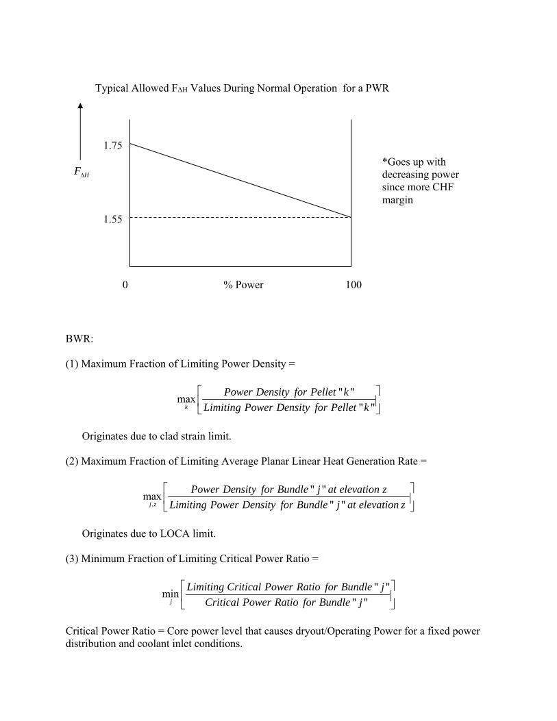
BWR: (1) Maximum Fraction of Limiting Power Density =
" "max
" "k
Power Density for Pellet k
Limiting Power Density for Pellet k
Originates due to clad strain limit.
(2) Maximum Fraction of Limiting Average Planar Linear Heat Generation Rate =
,
" "max
" "j z
Power Density for Bundle j at elevation z
Limiting Power Density for Bundle j at elevation z
Originates due to LOCA limit.
(3) Minimum Fraction of Limiting Critical Power Ratio =
" "min
" "j
Limiting Critical Power Ratio for Bundle j
Critical Power Ratio for Bundle j
Critical Power Ratio = Core power level that causes dryout/Operating Power for a fixed power distribution and coolant inlet conditions.
HF
Typical Allowed FΔH Values During Normal Operation for a PWR
0 % Power 100
1.55
1.75
*Goes up with decreasing power since more CHF margin