Embed Size (px)
Citation preview

Thermal Infrared Endoscope
A Major Qualifying Project
Submitted to the Faculty of Worcester Polytechnic Institute
in partial fulfillment of the requirements for the Degree in Bachelor of Science
in
Robotics Engineering
By
Matthew Collins (RBE&CS)
James Kradjian (RBE)
Ryan St. Hilaire (RBE&ME)
Chenggu Wang (RBE&ME)
Wentao Yuan (RBE)
Date: 4/25/19
Project Advisor: Professor Loris Fichera
Project Co-Advisor: Professor Gregory S. Fischer

Abstract
According to a 2017 report by Intuitive Surgical, the da Vinci Robotic Surgical System
was used in approximately 877,000 surgeries that year, and this number is projected to increase
in the future. During robotic surgical procedures, energy-based tools are frequently used to
perform tasks such as cauterization, i.e. heating up tissue to coagulate blood vessels. However,
the use of these instruments poses a risk of spreading thermal energy to surrounding tissues and
causing accidental damage to vital anatomy. To help mitigate this hazard, here we propose an
infrared-based, minimally invasive thermal camera endoscope that can be attached to the existing
instrument arms of da Vinci robot. This device will enable surgeons to monitor, for the first time,
the thermal interactions between surgical instruments and tissue, thus helping surgeons reduce
the risk of accidental injury, secondary to heat. Our thermal endoscope consists of a set of
modular tubes and independent transmission, allowing the camera to have a 180-degree view.
The acquisition of the video stream generated by our device is processed by a Robot Operating
System (ROS) node running on a Raspberry Pi, which then publishes the stream of thermal
images as a ROS topic at a rate of 8 Hz (close to the highest frame rate offered by the infrared
camera). We provide a sample application that displays the live thermal video on a computer
screen and discuss how in the future this application could be integrated on the console of a da
Vinci robot.
1

Acknowledgments
Thank you to Professor Fichera and Professor Fischer for advising this project.
Thank you to Katherine Crighton for facilitating this project by managing budget and ordering
supplies.
Thank you to Aatreya Chakravarti and Keion Bisland for their contribution to the electrical and
computer engineering aspects of this project.
2

Contributions Matthew Collins Software Design, C++ Publisher Code, MATLAB Subscriber,
Camera Debugging, ROS Configuration, Camera Validation, MATLAB Display, Graphing, and Modalities, Text Fixture Design
James Kradjian Software Design, C++ Publisher Code, Network Design and Configuration, Camera Debugging, ROS Configuration, Camera Validation, MATLAB Display and Graphing, Test Fixture Electrical Assembly and Testing
Ryan St. Hilaire Mechanical Design, Prototyping, Machining, Shaft and Transmission Design, Test Fixture Coding
Chenggu Wang Mechanical Design, Prototyping, Machining, Mechanical Integration and Testing, Kinematics Analysis
Wentao Yuan ROS Integration, C++ Publisher Node, Matlab Thermal Data Display, Output Validation Analysis
3

Table of Contents
Abstract 1
Acknowledgments 2
Contributions 3
Table of Contents 4
List of Figures 6
List of Tables 7
Executive Summary 8
1. Introduction 11
2. Background 13 2.1 Literature Review 13 2.2 Da Vinci Surgical Platform 13 2.3 Thermal Imaging Camera 14
3. Materials and Methods 15 3.1 Hardware Design Logistics 15
3.1.1 Design Objectives and Functional Requirements 15 3.1.2 Design Constraints 16 3.1.3 Preliminary Designs 17
Notched-Tube Design 17 Modular Linkage Design 18 Comparison of Preliminary Designs 20
3.1.4 Final Modular Shaft Design 21 3.1.5 Designing Arm Transmission 23
3.2 Software and Electronics Logistics 26 3.2.1 Design Objectives and Functional Requirements 26 3.2.2 System Overview 27
ROS 27 Catkin 28 MATLAB 28 Custom PCB 29 Raspberry Pi 29
4
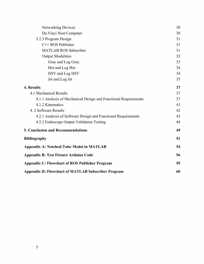
Networking Devices 30 Da Vinci Host Computer 30
3.2.3 Program Design 31 C++ ROS Publisher 31 MATLAB ROS Subscriber 31 Output Modalities 32
Gray and Log Gray 33 Hot and Log Hot 34 HSV and Log HSV 34 Jet and Log Jet 35
4. Results 37 4.1 Mechanical Results 37
4.1.1 Analysis of Mechanical Design and Functional Requirements 37 4.1.2 Kinematics 41
4. 2 Software Results 42 4.2.1 Analysis of Software Design and Functional Requirements 42 4.2.2 Endoscope Output Validation Testing 44
5. Conclusion and Recommendations 49
Bibliography 51
Appendix A: Notched-Tube Model in MATLAB 54
Appendix B: Test Fixture Arduino Code 56
Appendix C: Flowchart of ROS Publisher Program 59
Appendix D: Flowchart of MATLAB Subscriber Program 60
5

List of Figures
Figure 1: Da Vinci Cautery Tool and its Thermal Spread Figure 2: Final Mechanical Assembly Figure 3: Example Colormap, “jet”, with linear (left) and logarithmic (right) scaling Figure 4: Energy-based da Vinci instruments and their thermal spread Figure 5: Motor specifications for the da Vinci Research Kit(25) Figure 6: Notched-tube design for bi-directional bending Figure 7: Preliminary Design of the Linkage-Like Tube Model Figure 8: Improved Design of the Modular Link Model Figure 9: Solidworks model of the modular link Figure 10: Sectional view of the camera mount Figure 11: Thermal Infrared Endoscope Transmission Figure 12: Isometric Solidworks model of the torsional motor pulley Figure 13: Test Fixture for the dVRK Figure 14: System Architecture Diagram Figure 15: Example Colormap, “gray”, with linear (left) and logarithmic (right) scaling Figure 16: Example Colormap, “hot”, with linear (left) and logarithmic (right) scaling Figure 17: Example Colormap, “hsv”, with linear (left) and logarithmic (right) scaling Figure 18: Example Colormap, “jet”, with linear (left) and logarithmic (right) scaling Figure 19: Final Mechanical Build Figure 20: Modular Link Bend Radius Figure 21: Thermal Infrared Endoscope attached to the dVRK surgical robot Figure 22: Modular Link Bend Radius Figure 23: Boiling Water Validation Figure 24: Thermal Frame Publish Frequency Figure 25: Camera Validation Setup Figure 26: FLIR camera reading on object temperature at 55°C Figure 27: Reference camera reading on object temperature at 55°C
6

List of Tables
Table 1: Mechanical Design Comparison Table 2: Camera Validation Test Data in Celsius Degrees
7

Executive Summary
The purpose of this project was to develop a thermal infrared endoscope that was suitable
for minimally invasive robotic surgery. The rate of robot-assisted surgery has increased rapidly
over the year with 877,000 procedures performed with da Vinci alone in 2017 [1]. Minimally
invasive robotic surgery can be much more precise and much safer compared to open surgeries,
however, thermal damage can occur because of the use of cauterization equipment. Nerve tissue
is particularly sensitive to heat, and excess thermal spread can result in lifelong complications.
As of the writing of this paper, no commercial thermal endoscopes exist on the market.
Figure 1: Da Vinci Cautery Tool and Lateral Temperature Spread
(adapted from Hefermehl et al. [8])
Using a combination of surgical robots and thermography, cases of thermal damage can
be limited. Thermographic visualizations provide surgeons with live area temperature data that
allows them to see both the current temperature of and the thermal spread due to the use of the
tool (shown in Figure 1). The da Vinci Surgical Platform is a teleoperated robot used for surgery
and can be used as a development platform for instruments. Current instruments include optical
endoscopes, forceps, and cauterizers. Developments in the Long-Wave Infrared camera
technology have allowed for the creation of a distal tip endoscopic thermal imaging camera of
miniature scale to be practical in surgical applications.
In terms of mechanical design, the endoscope has two major features: the rotating shaft
and the transmission. The rotating shaft is the part of the mechanism that holds the camera, while
8

the transmission is the feature that controls the motion and bending of the shaft. The two major
design constraints for this mechanism is that the system must use the Lepton 3.5 camera and
must be able to be mounted on a da Vinci surgical robot through conventional means. The
preliminary designs involved building a notched-tube design for the shaft, but this was changed
due to the complexity of the part. The design that was ultimately chosen was a linkage-like tube
that used a series of modular links to bend. This solution was more robust and easier to create
than the notched tube and had the benefit of a more discrete kinematic solution. For prototyping
purposes, the modular links, camera enclosure, and shaft were 3D printed using SLA resin.
The modular links were linked between the main shaft and the camera enclosure and was
able to bend the enclosure 60º from the central axis. The bending of the links was controlled by
the transmission, an adapted da Vinci base plate that used a series of pulleys to pull tensioned
cables, resulting in a bend radius. The transmission contained a mix of 3D printed, machined,
and existing da Vinci parts, and this mechanism was successful in controlling the location of the
infrared camera. For standalone testing, the team also built a text fixture with three stepper
motors controlled by Arduino Uno. The kinematics for the modular link bend radius was
generated, relating the bend radius to the steps on the stepper motor of the test fixture. The
resulting relationship determined the number of steps per degree of bend radius, up to a
maximum of 60º.
Figure 2: Final Mechanical Assembly
9

The goal of the software and electronics designs are to facilitate the formatting and
presentation in an interpretable way to the surgeon. Several requirements were determined at the
start of the project by the team. These requirements were set to minimize the complexity to the
surgeon and other staff. The computer connected to the camera, the Raspberry Pi, is running
ROS, or Robot Operating System, and is acting exclusively as a publisher node. The job of the
Raspberry Pi is to transmit the images from the FLIR Lepton to the ROS network. From there,
any subscribers can subscribe to the topic where the frame is at. In this case, the subscriber is a
computer that is running MATLAB to interpret and display the frame. By using MATLAB, it is
easy to visualize in different color maps and modalities.
Figure 3: Example Colormap, “jet”, with linear (left) and logarithmic (right) scaling
Utilizing the jet colormap, a surgeon can easily and intuitively determine the hottest
regions in the frame. Depending on the preference, either a linear or logarithmic scale can be
chosen. The output of the camera was validated using the FLIR A655sc to determine that the
software that was written in a way that correctly interpreted and displayed the data.
The final iteration of the thermal infrared endoscope satisfies the majority of the
requirements set by the project, but there are several mechanical and software augmentations that
can increase the viability of the system as a medical instrument. The final product shows promise
as an initial attempt to reduce the amount of heat-related injuries during robotic surgery and is
useful in detecting the effects of energy-based instruments.
10

1. Introduction
The use of surgical robots has increased dramatically in the past few years. Between 2016
and 2017, the number of da Vinci surgeries has increased by approximately 16%, with nearly
877,000 procedures performed in 2017 [1]. These systems are mainly used for laparoscopic, or
minimally invasive surgery, involving the use of thin instruments inserted through small cuts on
the patient. Among all robot-assisted surgeries, approximately 75% of robot-assisted surgeries
are used for urology or gynecology procedures, with nearly 85% of all prostatectomies
performed in the United States using a surgical robot [2]. These surgical robots boast a quicker
procedure time and a shorter recovery period, but typically have similar long-term recoveries as
compared to open surgery. One study has shown that robot-assisted surgery is easier to learn for
people without any previous surgery experience [3]. Surgical procedures utilizing the da Vinci
are less expensive than open surgery as the latter causes a longer length of stay and additional
costs [4].
While minimally invasive robotic surgery can be more precise and safer than
conventional surgical methods, it is not without risks. Thermal damage is especially prevalent
when using these systems as they use cauterization to seal blood vessels and maintain a clean
work environment [6, 7, 8]. However, cauterizers must produce a significant amount of heat to
fully seal the vessels, and the radiative heat can be damaging to the body, as shown in Figure 4.
This can be very dangerous with surgeries that operate near a large volume of nerves. Nerves can
be permanently damaged at temperatures as low as 45ºC, and the cauterizers typically run
between 40ºC and 60ºC [11]. This leaves a very small margin of error, and thus controlling the
spread of heat is extremely important. An example of this is with the prostatectomies previously
mentioned. If enough heat is radiated to the nerves in or near the prostate, the patient could lose
all sensation and functionality in that region [5, 9, 10]. Due to these dangers, cautery tools are
not normally used for these sensitive procedures, making the procedure more difficult and
increasing the risk of potential complications.
11

Figure 4: Energy-based da Vinci instruments and their lateral temperature spread
(adapted from Hefermehl et al. [8])
The robotic surgical systems also introduce the risk of human operation error and
mechanical failure. Several components on the da Vinci robot can malfunction or break during
operation, compromising control or leaving a residue within the operation area [6]. This can
result in complications and longer recovery times. Currently, there are no commercially available
thermal endoscopes that can be used for robotic surgery. The motivation for this project is to
develop a viable solution to minimize heat trauma during robotic surgery, thus making the
surgeries safer and more effective.
12

2. Background
2.1 Literature Review
This idea of a thermographic-based surgical observation platform was brought up and
tested by Lin et al. [1]. Thermographic visualization can provide surgeons with live temperature
maps and monitor heat from cautery tool. Their team has experimented with a miniature IR
camera Lepton made by FLIR Systems. Controlled experiments were set up with 2 Lepton
cameras side by side and a higher resolution FLIR A655sc camera as a ground reference to
obtain thermal images. All three cameras observed the thermal spread of a chicken specimen
with statically matching data, thus proving the Lepton camera a viable option for observing
thermal energy transmission across the soft tissue [11]. The team plans to improve upon this
research both mechanically and digitally integrate the newest version of Lepton into an
endoscopic IR camera. In addition, with the resources we have on the da Vinci surgical system,
we are planning to attach the IR camera as one of the instrument arms on the da Vinci Research
Kit (dVRK) and achieve mechanical control of the endoscope.
2.2 Da Vinci Surgical Platform
The da Vinci Surgical Platform is a teleoperated surgery robot. The system has four arms
that instruments can be attached to, and each arm can be controlled independently with input
from the surgeon. These arms can hold cauterizers, cameras, forceps, and other surgical
instruments. During normal operation, three of the four arms are typically in use, with the fourth
reserved as a spare. The da Vinci system activates instruments by activating one of the four
motors embedded within each arm. These, in turn, rotate a set of pulleys housed within the
transmission of the instrument, allowing for motion and actuation depending on the instrument
attached. The system is extremely precise and can remain more steady when performing delicate
procedures than a surgeon alone.
13

Da Vinci instruments are typically very small, with a diameter of 8mm and smaller. This
is because the smaller the tool, the smaller the incision needs to be to insert the tool within the
patient. The overall length of the tool is usually between 30cm-35cm to prevent the surgical arms
from interfering with each other. To ensure that the instruments do not malfunction, the
instruments are typically only rated for 10-30 uses before being replaced. To prepare the thermal
infrared endoscope for similar surgical applications, the mechanism must be similar in build to
the current instrumentation, and it will be attached to one of the da Vinci arms.
2.3 Thermal Imaging Camera
LWIR, or Long-Wave Infrared, cameras are commonly used for near room temperature
detection by sensing infrared radiation within the range of 8-14 micrometers[12]. For use in
minimally invasive surgical applications, size and reliability are key features to consider when
choosing the camera model. Through our research, we found that FLIR manufactures a
radiometric-capable camera model, the Lepton 3.5. It has a built-in calibration feature, includes
160 by 120 pixels and is also made to be relatively low cost compare to other traditional IR
cameras. The Lepton 3.5 consists of a microbolometer array with a lens to focus. A
microbolometer is a ranged temperature sensor in miniature scale, and a microbolometer array is
many of these sensors put together, and therefore can form an image with temperature reading on
every single pixel [13].
14

3. Materials and Methods
3.1 Hardware Design Logistics
This section lists the design goals and functional requirements for the mechanical aspects
of this project. Starting from the given design constraints, this section covers the preliminary
design approaches, comparison of design options, and final design details.
3.1.1 Design Objectives and Functional Requirements
The goal of the mechanical design is to build an endoscopic camera that can be inserted
within a patient during minimally invasive surgery. This endoscope must be able to provide full
visual coverage of the operation space during the surgery and must be able to navigate while
under spatial constraints inside the patient, precisely following the teleoperation commands from
the surgeon. With these design goals in mind, the team has composed a list of functional
requirements listed below. The realization of each functional requirement will be discussed in
detail in the following sections.
Functional Requirements:
1. The size of the custom imaging endoscope needs to be in close proximity with
existing da Vinci instruments
2. The material of the endoscope needs to be rigid, non-deformable, and potentially
bio-compatible
3. The endoscope needs to have at least two degrees of freedom, and be able to reach
all designed orientations with proper actuation
4. The mechanism needs to tolerate wear within the average expected number of
operations
5. The endoscope needs to be self-contained, all components of the electronics and
mechanical transmission must be bounded within the instrument enclosure
6. The mechanism needs to be compatible with existing da Vinci system, allowing
easy integration and testing using the dVRK
15

3.1.2 Design Constraints
There are a few design constraints proposed by the selected camera module. While being
one of the smallest commercially available thermographic camera, the Lepton 3.5 camera [13]
has a dimension of 9mm by 9mm, setting the lowest bound of the dimensions of the design. The
57° horizontal field of view of the camera also determines the maximum rotation of the shaft
needed to fully observe the operation space. Additionally, the mechanism must be installed on
and driven by a da Vinci surgical robot. This means that the system must be actuated by the drive
motors already present on the dVRK system using a specific motor mounting configuration
while staying below the maximum torque of the robot for Outer Roll (0.044 Nm, See Figure 5).
Finally, the system must be self-contained and have all wiring held within the mechanism during
operation. This includes the signal wires for the camera as well as the actuation pulleys.
Figure 5: Motor specifications for the da Vinci Research Kit[14]
16

3.1.3 Preliminary Designs
The main design challenge for this project was to design a flexible shaft that could be
controlled using tensioned pulleys. There were two major design paths in the early stages of this
project. Based on common continuum instruments used in surgical applications, the team came
up with a couple of preliminary models of the endoscope as described in this section.
Notched-Tube Design
The first design of our consideration was a notched-tube endoscope made out of nitinol, a
superelastic nickel-titanium alloy. The notched-tube joint design has been utilized for various
medical devices involving miniaturized wrists, and many of the mechanisms achieve directional
compliance by creating notches on superelastic nitinol tube [15,16]. Actuation is achieved by
applying tension on the tendon, usually through a stainless steel cable routed on the tip, causing
the tube to bend. The kinematic behavior of this mechanism depends on the internal material
deformation and the structure of the tube, which can be characterized using a series of
transformation matrices provided by Eastwood et al. [17]. A script of the equations used written
in MATLAB is included in Appendix A. These equations provide a theoretical model of the
maximum bending angle, stress, and strain of the endoscope based on its geometry. In particular,
once we input the number of notches, depth and width of notches, and the space in between
them, the script will generate the theoretical maximum bending without considering the material
strength. We then verify if a given material can sustain the amount of strain, and calculate the
max stress based on Young’s Modulus of the material. This process is repeated until an optimal
geometry is found that works for the selected material and produces desired kinematic output.
The team considered three main criteria for the design: tube diameter, wall thickness, and
maximum bending angle. To start with, we decided to keep the outer dimensions of the geometry
the same as the original da Vinci instrument tubes. In terms of the bending angle, since our
Lepton 3.5 camera has a field of view of 57 degrees horizontally, we decided that a 60 degree
bending to both sides would achieve roughly 180-degree view. Therefore, with these parameters
17

in mind, we formulated the transformation matrices and generated the design shown in Figure 6
below.
Figure 6: Notched-tube design for bi-directional bending
Since nitinol is expensive to manufacture and difficult to obtain in small quantities, a few
proof-of-concept tests were performed before pursuing the design with nitinol tube. The above
model was 3D printed for testing using TPU elastic plastic. However, the result from the initial
prototype was not ideal. The printout did not endure much tension before shattering and was not
able to recover to the original orientation. This was due to the mechanical weakness that lies
within the method of layer by layer material jetting (the most common type of 3D printing). It
was also observed that the wall sections in between notches were subject to huge strain and
became weak points in the bending motion. Overall, the part was not able to sustain bending
stress and failed as a testing prototype.
In addition to the elastic-plastic test print, we also tested the notched-tube model on W1
tool steel. This material was chosen because of its similar resilience to spring steel and nitinol.
However, due to its high Rockwell hardness and modulus of elasticity, the W1 tool steel was
very difficult to machine into the notched tube and required an extreme amount of force to bend.
As a result, it was decided this notched tube design is not suited for our endoscope design since
the risk of using nitinol is too high after both concept models have demonstrated material failure.
Modular Linkage Design
An alternative design option the team had was a linkage-like modular tube design. Each
link section is able to achieve some degree of bending individually and will be connected
together by pin joints. Shown in Figure 7 below, the initial design of the modular linkage had an
inner tube section and an outer tube section. The modular linkage can be stacked on top of itself
and the pin holes will be held by two metal pins. The inside of this tube is completely hollow,
leaving all the space for signal cables in addition to having two ditches for the tension cables.
18

Figure 7: Preliminary Design of the Linkage-Like Tube Model
After sending this model for 3D printing, the team soon realized the problem. Since one
of these design goals is to keep the endoscope as small as possible, there was little room left for
wall thickness especially around the pin connectors, leaving it extremely easy to fracture.
Additionally, it was discovered that there was no significant advantage to have two different
diameters for either end of the link. Moreover, the idea of adding a separation along the length of
the tube was brought up during the design review process with the aim to provide cable
separation, reduce tangling and provide additional structural support.
Figure 8: Improved Design of the Modular Link Model
Shown in Figure 8 above, the improved modular link design has a uniform diameter
throughout its cylindrical shape. The inside has a separation wall running along the length of the
linkage, connecting to the pin joints at both ends. To increase the structural stiffness at the pin
connectors, we decided to make the make then into a hinge-like structure with odd and even
ends. The connection pins were also replaced by one bolt going through the diameter of the shaft,
allowing the hinges to rotate freely. After printing this improved model and testing it with our
19
setup, all aspects of the design was shown to be functional. The new hinge-like pin joints were
rigid enough to complete designed bending, and the center of the shaft still offered enough space
for the signal cables and tension cables.
Comparison of Preliminary Designs
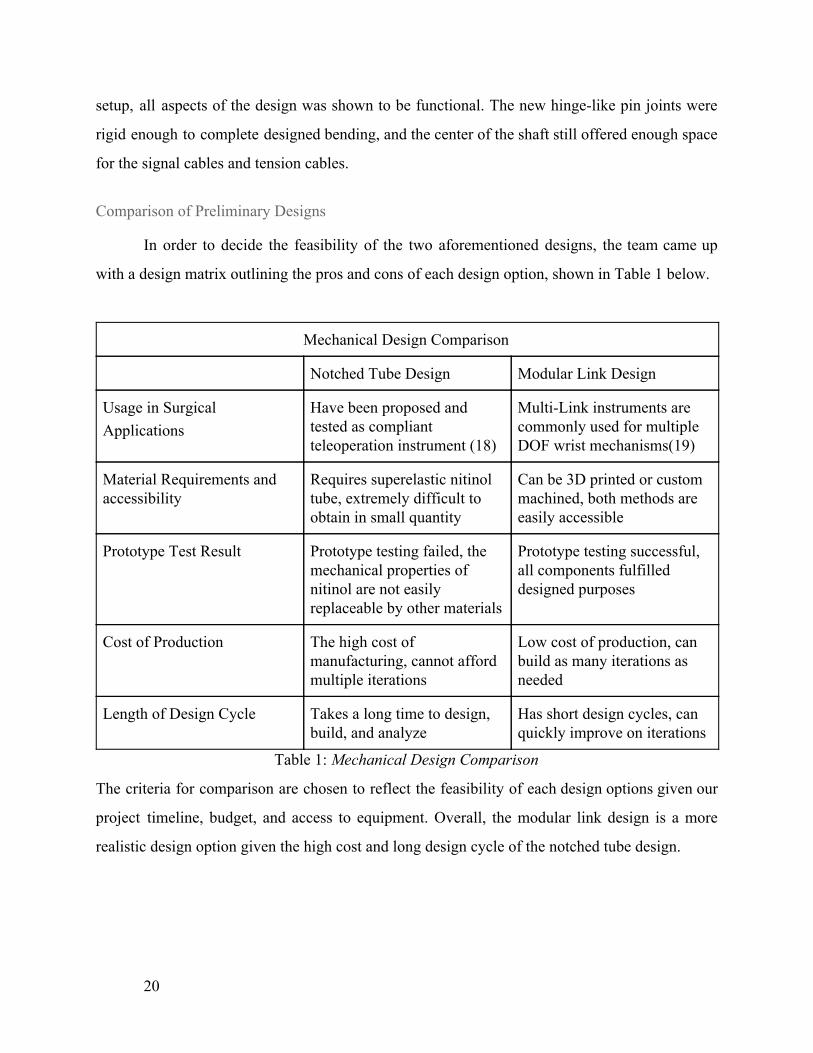
In order to decide the feasibility of the two aforementioned designs, the team came up
with a design matrix outlining the pros and cons of each design option, shown in Table 1 below.
Mechanical Design Comparison
Notched Tube Design Modular Link Design
Usage in Surgical Applications
Have been proposed and tested as compliant teleoperation instrument (18)
Multi-Link instruments are commonly used for multiple DOF wrist mechanisms(19)
Material Requirements and accessibility
Requires superelastic nitinol tube, extremely difficult to obtain in small quantity
Can be 3D printed or custom machined, both methods are easily accessible
Prototype Test Result Prototype testing failed, the mechanical properties of nitinol are not easily replaceable by other materials
Prototype testing successful, all components fulfilled designed purposes
Cost of Production The high cost of manufacturing, cannot afford multiple iterations
Low cost of production, can build as many iterations as needed
Length of Design Cycle Takes a long time to design, build, and analyze
Has short design cycles, can quickly improve on iterations
Table 1: Mechanical Design Comparison
The criteria for comparison are chosen to reflect the feasibility of each design options given our
project timeline, budget, and access to equipment. Overall, the modular link design is a more
realistic design option given the high cost and long design cycle of the notched tube design.
20

3.1.4 Final Modular Shaft Design
In the end, the team chose to pursue a modular link mechanism design with a customized
transmission. To meet the required functional requirements and comply with the design
limitations, a modularly linked shaft was designed. This mechanism consisted of a series of
pinned links that interfaced with each other to bend at discrete angles. The mechanism would be
manipulated with two tensioned cables and would remain kinematically stable as long as the
cables were in proper tension. To house the camera electronics and tensioned cables, the shaft
would be hollow with the cables running from the end effector to the shaft transmission.
Additionally, the shaft could be rotated using a third tensioned cable wound around the
circumference of the shaft.
The modular link was a significant feature to the modular shaft design and was the main
feature that determined the bend angle. Shown in Figure 8, the modular link has two 15º facial
cuts on both ends, measured from the center of the hinge. The camera mount (Figure 10) and the
shaft (Figure 10) have similar 15º cuts, but only on the side where the modular link would attach
to. When the hinges are connected between the camera mount, shaft, or another modular link, the
total bend angle between the two features is 30º. The addition of the modular link allowed the
mechanism to modify lengths as well as change the bend angle by modifying the facial cuts on
the link. The link contains the same central partition as the shaft, shown as the central blue walls
in Figure 9, and features specific, notched geometry to provide a crevice for the tensioned cable
to ride in.
21

Figure 9: Solidworks model of the modular link. Walls are highlighted in blue in the left
image, and a top-down view is shown in the right image
Based on the field of view of the camera, our team determined that the manipulator only
needed to bend by a total of 60º from the central axis to achieve a full view of the operation
space. To achieve this, each joint was designed with a 15º cut at the top and bottom faces. Thus,
when bent, each linkage would result in 30º of bending to maximize the kinematic motion. While
the mechanism can have as many links as desired, this particular design only required a singular
link in the middle, assuming the camera mount and connector shaft had the same facial cuts,
resulting in the required 60º bend.
The modular shaft also contained an internal partition to separate the tensioned cables.
This was done to ensure that the cables would not twist together during shaft rotation. To
maintain a symmetrical bend radius, the camera wires were split equally between the two
partitions. This also helped to stabilize the mechanism and prevent the mechanism from moving
erratically during testing with the stepper motors.
The camera mount is designed to carry the Lipton camera and the miniaturized PCB.
Shown in Figure 10, the camera mount is designed to be as small as possible, with the diameter
of the enclosure being slightly larger than the camera diameter. The final head dimensions for the
camera mount are 14mm by 14mm, and the length is 40mm to allow enough space to house the
soldered the camera wires. The camera mount also has a pair of angled holes within the stem to
pass the tensioned cables through. The tensioned cables are then fixed to the shaft with a
22

clamped sleeve such that the cable can not slip back through the holes. Thus, when the cables are
pulled, the cable length effectively becomes shorter, bending the manipulator in the pulled
direction.
Figure 10: Sectional view of the camera mount. Note the two 45º holes in the stem of the
mount for the cables to pass through
Since the modular shaft had so many irregular features making it hard to machine, the
shaft, modular link, and camera mount were 3D printed using an SLA resin on the Formlabs
Form 2 printer. The print had a very high resolution of features, but sometimes had trouble
retaining its shape during UV post cure. Additionally, the resin was not as strong as initially
expected, any unexpected external force can cause the parts to break during testing and
operation. This was especially prevalent between modular links as the hinges were very thin and
could easily experience extreme shear forces if the links were pulled or if the shaft was bent
beyond the 60º bend radius. The reason for using the SLA resin was because the Formlabs
printer has high resolution and quick turnaround time whereas creating the shaft without 3D
printing would have been extremely time consuming and less iterable.
3.1.5 Designing Arm Transmission
To control the chosen shaft design, a transmission system was built to interface with the
existing dVRK system, shown in Figure 11. As mentioned previously in the design limitations,
this transmission would be driven using the motors present on the da Vinci system. These motors
would drive a series of transmission mounted disc under the baseplate, which would in turn wind
a pulley mounted on each pole. These pulleys each control a singular degree of actuation by
23

pulling on tensioned cables. With the cables running through the shaft, the resulting motion
would cause the end effector to move in direct response to the motor input. Thus, the
transmission is used to convert motor rotation into the end effector movement. This simple
system makes it straightforward for the team to develop a moving mechanism and helped us
determine how the modular shaft system should be designed.
Figure 11: Thermal Infrared Endoscope Transmission
Initially, this transmission was to be built from scratch, but the team decided to instead
reuse an existing da Vinci tool as it already contained the majority of the parts necessary to
control the mechanism. The baseplate was reused, allowing for simple and repeatable attachment
to the dVRK, and the motor shafts and plate bearings were also reused to better control the
tensioned cables.
In order to control the bend of the modular shaft design, the original transmission system
included a set of pulleys that held the ends of the tensioned cables. These pulleys were mounted
through the original motor shafts and would clamp to the shafts using set screws. The existing
transmission pulleys were able to pull the tensioned cables for the necessary motions, but the
cable clamps were too small of a diameter to fit the intended cables. These existing pulleys could
not be reused since the process of increasing the cable clamp diameter would have destroyed the
part. Therefore, the team created new torsion pulleys by measuring existing pulleys and
24
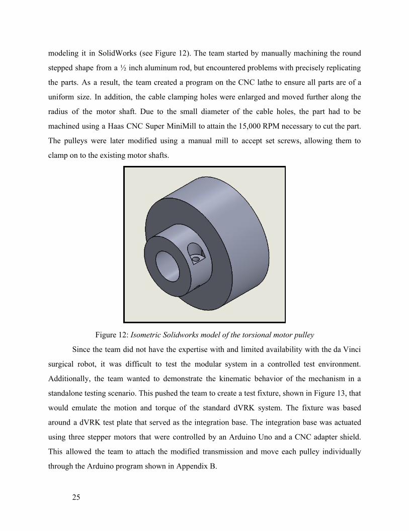
modeling it in SolidWorks (see Figure 12). The team started by manually machining the round
stepped shape from a ½ inch aluminum rod, but encountered problems with precisely replicating
the parts. As a result, the team created a program on the CNC lathe to ensure all parts are of a
uniform size. In addition, the cable clamping holes were enlarged and moved further along the
radius of the motor shaft. Due to the small diameter of the cable holes, the part had to be
machined using a Haas CNC Super MiniMill to attain the 15,000 RPM necessary to cut the part.
The pulleys were later modified using a manual mill to accept set screws, allowing them to
clamp on to the existing motor shafts.
Figure 12: Isometric Solidworks model of the torsional motor pulley
Since the team did not have the expertise with and limited availability with the da Vinci
surgical robot, it was difficult to test the modular system in a controlled test environment.
Additionally, the team wanted to demonstrate the kinematic behavior of the mechanism in a
standalone testing scenario. This pushed the team to create a test fixture, shown in Figure 13, that
would emulate the motion and torque of the standard dVRK system. The fixture was based
around a dVRK test plate that served as the integration base. The integration base was actuated
using three stepper motors that were controlled by an Arduino Uno and a CNC adapter shield.
This allowed the team to attach the modified transmission and move each pulley individually
through the Arduino program shown in Appendix B.
25

Figure 13: Test Fixture for the dVRK
3.2 Software and Electronics Logistics
3.2.1 Design Objectives and Functional Requirements
The goal of the software design is to format and display the thermal data output by the
camera. The output display modality should allow for easy visual interpretation of heat within
the image. The design of the software system should allow for the connection of multiple clients
for use with multiple output displays. Similarly to the mechanical requirements, the team
generated functional requirements for the software system design. The results of the software
design and an analysis of the software design requirements will be discussed in the Results
section.
Functional Design Requirements:
1. Cables external to the endoscope package must not interfere with normal robot
operations, and therefore the count must be minimized.
2. Additional clients must be easy to configure, to allow multiple screens to read and
interpret the data with different modalities in the future, depending on the operation.
3. Thermal data should be displayed with a colored image.
26
4. The system should have latency lower than 75ms because otherwise, the delay becomes
noticeable enough to a person to cause perceived performance decrease, and therefore
potentially impacting the ability of the surgeon to precisely control the device.[23]
5. Software will be developed using C++ and/or MATLAB.
6. The surgeon should be able to set a temperature threshold for warning.
7. The surgeon should get a warning once the threshold is reached.
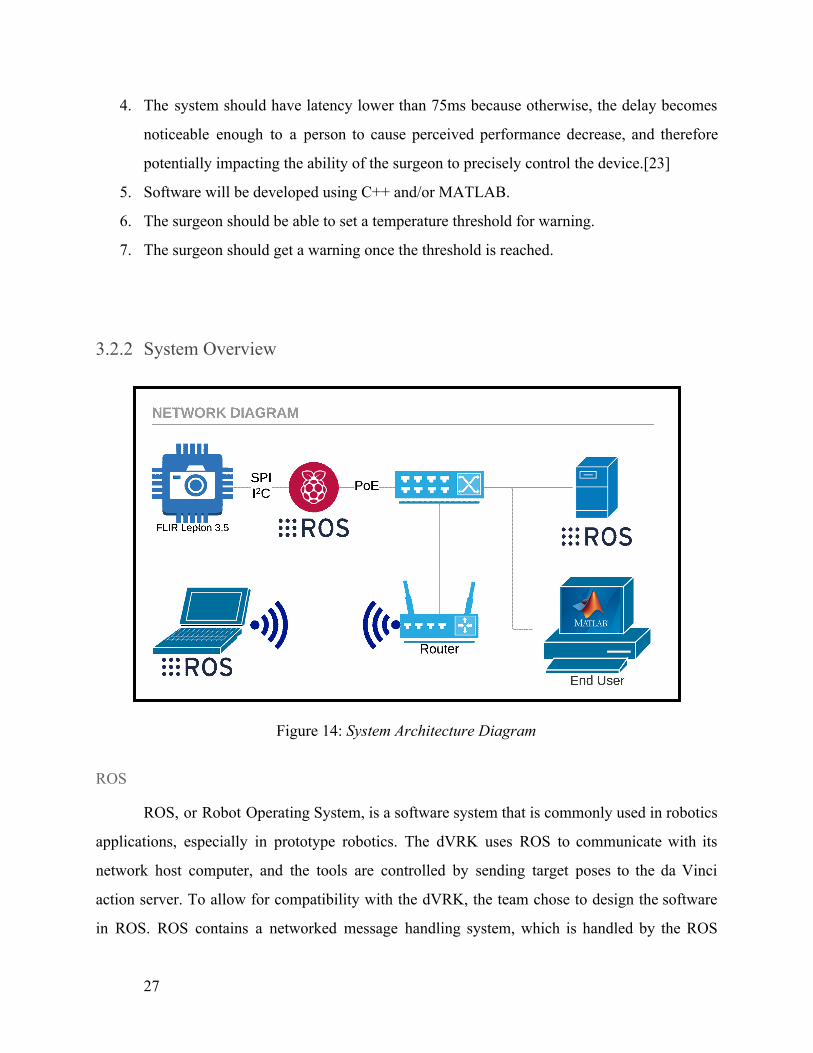
3.2.2 System Overview
Figure 14: System Architecture Diagram
ROS
ROS, or Robot Operating System, is a software system that is commonly used in robotics
applications, especially in prototype robotics. The dVRK uses ROS to communicate with its
network host computer, and the tools are controlled by sending target poses to the da Vinci
action server. To allow for compatibility with the dVRK, the team chose to design the software
in ROS. ROS contains a networked message handling system, which is handled by the ROS
27

master core. The message handling system allows for a publisher-subscriber model which
handles network transport protocol for the user across both C++ and Python systems. The ROS
network runs individual programs in nodes, which allow for distributed computing in robotic
systems. The node system allows for easy reconfiguration based on node selection. The node
system also increases the ease of prototyping, as new nodes can be added to the network to test
new functionality. In the case of a surgical endoscope, ROS allows for easy reconfiguration in
the number of end users and of display modalities, which is especially useful for prototyping
systems. Different surgeons may prefer different display modalities, or different staff and
different operating theatres might allow for different setups for the endoscope display. By using
ROS, we are able to keep an expandable system built around utilizing the endoscope to the
fullest.
Catkin
Catkin is the custom build system used in recent versions of ROS. It is developed for, but
also independently of ROS. Catkin facilitates easy management of packages and dependencies.
Catkin is responsible for linking the ROS and the GroupGets Lepton Module thermal library
[24]. Catkin is very light in dependencies, and only requires Python and CMake to run. Programs
that are built for the Raspberry Pi in this project are built using the Catkin build system.
MATLAB
MATLAB is a software package that is used in engineering and scientific applications for
analysis and design. MATLAB contains powerful tools for graphing and data analysis of matrix
data and can generate color-mapped images with value labeled color bars, which is why it was
picked for use in this project. MATLAB also has a built-in ROS toolbox which allows for data to
be captured in real-time from a running ROS network in a MATLAB subscriber node. One major
benefit of MATLAB is that it is designed to work with engineering equations like kinematics. In
the future, given the exact kinematics of the endoscope mechanism and the thermal data stream,
MATLAB can generate custom target pose messages to be published to the dVRK over the ROS
network. The built-in mathematics functions of MATLAB are well-suited to manipulating
28

equations for prototyping and control, and the graphing functions of MATLAB allow for easily
customizable data analysis.
Custom PCB
A custom Lepton interface board was designed on-campus by Keion Bisland for use in
this project. The PCB breakout allows the camera to connect to a SPI and I2C host and also
provides power regulation and a clock signal. Although FLIR produces a proprietary PCB for the
camera, the package size of this PCB is significantly greater than is necessary by design. A
custom designed, stacked multi-layered board allows for more compact package size. If the PCB
is re-designed into a multi-layered circuit board, the physical size of the board is constrained
almost entirely by the external width of the camera socket.
The primary objective in the design of the new PCB was to shrink the footprint as much
as possible. Along with this goal, a number of considerations had to be made; these include the
lack of documentation on the required supporting components for this development board, size
constraints of the components, reduction of noise induces on the communication lines and the
production process and selection of components to ensure the final product was free of lead and
any other hazardous chemicals.
After designing the schematic for the board the footprints were assigned and the board
outline made. It was then decided to split the components between two circuit boards that would
be split apart after assembly. The upper of these two boards would house the camera module
holder, the cameras associated 25MHz crystal oscillator and 1.27mm pin headers to connect to
the second board. The lower of these two boards would contain the power regulation and
supporting components as well as the communication and power connections to connect to the
Raspberry Pi. This two-board system allowed us to reduce the footprint of the overall
development board to the dimensions of the camera socket, being 11.5mm x 11.5mm, the
smallest it could be made continuing to use the FLIR Lepton Camera.
Raspberry Pi
To reduce the interference that would be caused by an extremely long serial connection,
and to increase the range of the thermal camera signal beyond the maximum length of a serial
29

data line, a Raspberry Pi 3B is used as a host for the Lepton camera to transfer raw data to the
ROS network. In the current version of the prototype, the breakout board wires connect directly
to the GPIO pins of the Raspberry Pi, which allows the ROS thermal data publisher to connect to
the Lepton. The Raspberry Pi then publishes data to the ROS network over the Ethernet
connection.
Networking Devices
The router is simply used as a DHCP host. Using a DHCP-equipped router was the
easiest way to allow the Raspberry Pi and the host computer to switch between the private
network and the internet for package installs and updates, along with connecting to version
control software. If the capability was required, the router would also let the endoscope to
connect to wireless devices.
The switch chosen for use in this project is a TP-Link 8-Port Fast Ethernet switch. This
switch was chosen for its Power over Ethernet feature. Power Over Ethernet facilitates all
communications between the host computer and the Pi with less danger of wire tangling by
reducing the number of wires, and by increasing the maximum distance between the endoscope
and the host computer significantly. Ethernet wire is also cheap and easy to crimp, which is a
significant benefit for a research project. Another benefit of a single Ethernet wire is that
Ethernet is thickly jacketed, which helps provide some limited protection against external
interference or any possible mechanical pinching, especially when compared to the small, easy to
tear serial wires used to connect to the breakout board.
Da Vinci Host Computer
The way the entire project was set up allows the use of the host computer of the da Vinci
robot to connect to the Pi directly over ROS. The host computer of the dVRK runs the ROS
master host, which coordinates ROS messages for the da Vinci. While this iteration of the project
did not directly make use of dVRK host computer, it allows for easy expansion into the robot
host computer in the future by simply switching startup configuration by running the publisher
and subscriber nodes in the native da Vinci network. The da Vinci Host computer would run the
only master node in the system, and any nodes set up control the da Vinci can be run on the host
30

computer, allowing the display host computer to fully focus its resources on rendering the
incoming data quickly.
3.2.3 Program Design
C++ ROS Publisher
The C++ ROS Publisher is responsible for publishing thermal data to the ROS network.
The camera is connected to the Raspberry Pi using the custom PCB over an SPI and I2C. Upon a
successful connection, the camera will send thermal data packets to the Raspberry Pi over SPI.
The thermal data packets are then assembled into complete image frames. A single image frame
is a fixed-width integer image vector representing the temperature in Kelvin. The temperature
data is initially represented in a scaled integer format. To clarify, the output data is scaled by 100
and truncated at the decimal point, therefore, the lowest two integer digits of the temperature
represents the first two decimal digits of the temperature in Kelvin. This integer scaling is for
image transport only, the thermal data will be converted to floating point and scaled using the
greater resources of the display desktop. The image vector is published to the ROS network
using a single node, which repeatedly publishes to the /image topic as quickly as images are
received from the Lepton. A flowchart depicting the functional flow of the ROS publisher
program is included in Appendix C.
MATLAB ROS Subscriber
The end user receives thermal image packets from the network, does any transformations
necessary to the picture for the desired output modality, and outputs the transformed data for
display. To reduce the amount of work that runs on the relatively lower processor power
Raspberry Pi, most of the graphics and matrix computations are left to the implementation and
processing of the desktop end user. For the purposes of this project, a MATLAB image vector
subscriber was determined to be sufficient for prototyping data coloring and analysis. When the
thermal data is received, the scaled image is first converted to a floating point representation
which accurately represents the temperature in Kelvin. Elementwise matrix operations are then
applied to efficiently convert the entire image from Kelvin to degrees Celsius. Once the Celsius
31

image data is formatted correctly, the data can be transformed into an appropriate color scale for
display on the UI using MATLAB’s built-in colormap selection. A flowchart of the MATLAB
subscriber program is included in Appendix D.
Output Modalities
The built-in graphing features of MATLAB has a dynamic color map with many preset
options. Depending on the colormap selected, the range of temperature values in the thermal
image are mapped to a colored gradient. The purpose of color mapping is to allow for easy visual
interpretation of sensor data. In our project, the main goal of the display modality is for the
surgeon to be able to recognize the temperatures throughout the thermal image without spending
time understanding the color scale, while still highlighting variation throughout the data. Along
with a colormap, a color bar with labeled ticks is generated as a key to the mapping. The hottest
and coldest temperatures in the frame determine the range of the color bar and of the range of the
color gradient. As the colorbar and colormap are updated dynamically with each new frame, the
colors adjust based on the temperatures in the frame. Creating an application-specific custom
static colormap was outside the scope of this project, but developing a custom static colormap
which would allow for a high-contrast highlighting of dangerous temperatures. Another
consideration is that the temperature range in basic demonstration images or in validation images
is very different from the temperature range in a real application of the medical endoscope, and
so this should taken into account when selecting a display modality.
Logarithmic scaling is a secondary method of displaying the thermal image data.
Logarithmic scaling would have allowed a wider range for colder temperatures while
compressing the higher temperatures together. The benefit of displaying this way is that even if a
specific area in the frame of the image remained very hot, such as while the cautery tool is being
tracked, the rest of the frame would not change significantly in dynamic scaling. As a result,
variations in temperature towards the lower range of temperatures retain a higher amount of
detail. The drawback is that the area with the highest temperature would not have as wide of a
range to display the finer variance in recorded temperature. Whether logarithmic scaling is useful
32
is very dependent on the range of temperatures in the image, and thus it would be significantly
more useful over a static, given range.
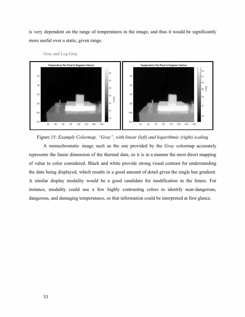
Gray and Log Gray
Figure 15: Example Colormap, “Gray”, with linear (left) and logarithmic (right) scaling
A monochromatic image such as the one provided by the Gray colormap accurately
represents the linear dimension of the thermal data, so it is in a manner the most direct mapping
of value to color considered. Black and white provide strong visual contrast for understanding
the data being displayed, which results in a good amount of detail given the single hue gradient.
A similar display modality would be a good candidate for modification in the future. For
instance, modality could use a few highly contrasting colors to identify near-dangerous,
dangerous, and damaging temperatures, so that information could be interpreted at first glance.
33

Hot and Log Hot
Figure 16: Example Colormap, “Hot”, with linear (left) and logarithmic (right) scaling
The range of colors used in Hot is both easy to interpret immediately and provides
excellent contrast between the lowest colors in the frame with the hottest (shown in Figure 16). If
the camera was being used inside of a patient, the majority of the image would be in the black to
red range, and the hottest part of the image, the heated tool, would transition between orange to
white. The low number of hues in the gradient results in a loss of detail over wide temperature
ranges. With a small temperature range in the image, or by cropping to the minimum color above
the majority of the image, this difficulty could be resolved.
HSV and Log HSV
Figure 17: Example Colormap, “HSV”, with linear (left) and logarithmic (right) scaling
34

The HSV colormap goes between bright blue at the mid-range to dark blue, then bright
again pink at the higher end of the scale range, which is too visually jarring and chaotic for easy
interpretation (shown in Figure 17). Due to the bright transitions and high amount of color
variation, HSV is well suited for showing small differences in very low contrast images. During a
robotic operation, the heated tip and the flesh temperature would both be in the frame, which is a
large difference in temperatures. HSV works well for low-contrast images, or for depicting a
small range in temperatures.
A significant downside of HSV is that the scale wraps around at the color red, which
creates confusion between the highest and lowest values. Another major issue with HSV is that
red is normally thought of as a hot color, and is typically grouped with yellow and orange, which
are at the bottom of the scale. The hue transitions between blocks of temperature are very bright
and are harder to interpret at a first glance, which is why HSV was not used for demonstration
purposes. HSV is not recommended in the future while using a dynamic color bar, except for the
specific applications where the majority of the image would be in only a small fraction of the
temperature range, which should never be the case in robotic surgery, or in a low-contrast mode
display mode.
Jet and Log Jet
Figure 18: Example Colormap, “Jet”, with linear (left) and logarithmic (right) scaling
35

Jet is the colormap chosen for our demonstration and poster images because it provides
an easy to interpret the image for the range of values used (shown in Figure 18). The rainbow is a
natural color spectrum that people are instantly familiar with, and thus is a powerful aid in
reading thermal images coded using this colormap. The changing hues contrast well against the
background color and show details without oversaturating. The range of colors in the gradient
transition smoothly, but also in a way that allows for immediate interpretation, unlike HSV, and
the wide range of colors in the gradient allows for a more granular visual resolution than simpler
gradients like Gray or Hot, which is why Jet is the default modality used to generate thermal
images in our project.
36

4. Results
4.1 Mechanical Results
4.1.1 Analysis of Mechanical Design and Functional Requirements
The final mechanical design, shown in Figure 19, was successfully able to meet the
majority of the functional requirements stated in section 3.1.1 and performed well while on the
test fixture. These functional requirements were created to set a baseline for the design and
operation of the mechanism, and based on the results the mechanism shows potential, but there
are still areas where the mechanism can be improved.
Figure 19: Final Mechanical Build
The first functional requirement stated that the overall size of the endoscope should be
similar to existing da Vinci instruments. While the camera mechanism is limited by the 9mm by
9mm camera, the addition of the stacked PCB and the camera enclosure increased the height and
37

width of the mechanism to 14mm by 14mm. Typical da Vinci mechanisms have a diameter of
8mm, but by modifying the PCB and changing the camera enclosure material from SLA to
stainless steel or aluminum, the enclosure can be smaller and more compact. As such, the team
believes that this system can be made smaller in the future to become more viable in the
laparoscopic environment.
The material of the mechanism is quite important, as the mechanism is intended to be
inserted within a patient. As such, the material used must be rigid, non-deformable, and
biocompatible. For this system, the camera enclosure, modular link, and shaft were all made out
of SLA resin. This resin was not biocompatible and was mostly rigid, making it not very usable
as a final product. This material was initially selected because the team needed to make quick
iterations of the mechanism design and the design had small, detailed features that could only be
printed using a high-resolution printer. The only printer available and suited for such purpose
was the Formlabs Form 2 printer. The company offers very limited biocompatible resin at a high
cost, as such the team decided that using regular rigid material will be sufficient for prototyping
knowing that the final mechanism would need a more applicable material. The SLA parts for this
system had some trouble holding the intended shape during the curing process, resulting in bent
and skewed shafts. The shafts were usable for demonstration and prototype purposes, but require
a stronger material, such as stainless steel to reinforce. For example, the hinge pins and
tensioning cable were made from stainless steel to provide additional structural support.
The final mechanism was successfully able to reach all desired orientations using a
two-degree of freedom design shown in Figure 20. The tensioned stainless steel cables can bend
the modular shaft by 60º from the central axis and can twist the shaft by 360º in both directions.
The combination of the bendable link and a rotating shaft allows the camera to observe the space
in a 360º cone from the base of the modular link. With the 60º bend and a field of view of 57º,
the camera is able to view up to 88.5º from the central axis, making it more than sufficient to
view the proposed surgical area.
38

Figure 20: Modular Link Bend Radius
In terms of mechanical repeatability, the mechanism was able to fully cycle more than 30
times without mechanical failure. However, the team was not able to generate a full fatigue
analysis for the proposed link and camera module. Existing da Vinci instruments are typically
rated for 10-30 uses, where in each operating the tools are articulated numerous times. The goal
of the mechanism is to match this operating condition with no breaks or fractures, however the
team was unable to verify this claim due to unexpected fractures. These fractures occurred when
extreme external forces were applied to the links while the mechanism is connected, where the
spike of shear stress caused the hinge connections to fail. The robustness and repeatability of the
mechanism can be improved by switching from the SLA resin to a stronger material as
mentioned before. In particular, stainless steel, aluminum, or injection-molded plastic would be
ideal, but the SLA was suitable for the initial prototyping.
Due to the nature of minimally invasive surgery, it is important to ensure that the cables
and wires are contained within the mechanism at all times during the surgery. The hollow shaft
and partitioned modular links allow the camera wires and tensioned cables to pass through the
mechanisms to the camera enclosure without outside exposure. To fully enclose this mechanism,
however, it would be necessary to include a flexible, biocompatible sheath around the area of
bending. The angled cuts of the mechanism could also potentially pinch the patient during the
operation, and the interior would be open to contamination. In the past, low-density polyethylene
39

has been used in medical applications, and the ductility of the plastic could allow this material to
be used as a sheath.
By using an existing da Vinci instrument baseplate as the basis for the transmission, the
mechanism was able to attach easily to the dVRK system, as shown in Figure 21. Additionally,
since the test fixture has the same interfacing geometry as the dVRK, the mechanism can be
attached to the test fixture and manipulated using Arduino inputs. This saved the team time in
developing a testable solution and ensured that the mechanism would perform as expected when
attached to the dVRK.
Figure 21: Thermal Infrared Endoscope attached to the dVRK surgical robot
40

4.1.2 Kinematics
Figure 22: Modular Link Bend Radius
To determine the relationship between the stepper motor steps and the bend angle, the
change in cable length was correlated with the resulting bend. In order to bend the mechanism,
the cable length is shortened by reeling in the tension pulley. This reduces the link separation
(denoted as L in Figure 22), and this change is directly correlated with the change in angle. Note
that with multiple links, the change in cable length is equal to the total L. To determine how
many stepper motor steps are necessary to produce a certain bending angle, the change in cable
length can be divided by the pulley circumference and converted to the angle of rotation at the
pulley. With the degrees per step known for the particular stepper motor (1.8º per step), the
resulting pulley rotation can be divided by the degrees per step to obtain the total number of
steps needed to achieve the desired bend angle. This process is shown below:
3.16mm, ΔL 6.32mm L = =
.36mm (pulley radius) (circumference) 2πr 4.83mm r = 2 → C = = 1
41

teps for 60º bend (L/C)/(1.8º/step) 5.24 ≈ 85 steps S : = 8
teps per degree 85 steps / 60º .42 steps/deg S : = 1
4. 2 Software Results
4.2.1 Analysis of Software Design and Functional Requirements
The use of cables to one coming out of the endoscope was minimized by making use of
Power Over Ethernet. By utilizing Power over Ethernet, a single cable to the unit allows for both
power and data to be transmitted. Ethernet is a low-cost wire which can be manually crimped at
the desired length, which allows for the system to be easily equipped with a proper length cable.
Without Power Over Ethernet, the Raspberry Pi requires a micro-USB power cable separate from
the Ethernet cable used to the connect to the ROS network. The issue with using a micro-USB
power cable to power the Raspberry Pi is that the maximum length of USB cables is strictly
limited by the USB standard, which poses a tangle risk with objects or people in the vicinity of
the robot, or with other arms of the robot itself. Although the PoE solution was successful, the
electronics of the endoscope must be consolidated in order to provide a fully safe solution.
ROS allows for easy configuration of multiple clients by utilizing the centralized ROS
core combined with the publisher and subscriber model. The Raspberry Pi publishes the thermal
image data over the ROS network to the /image topic. From there, other ROS clients can become
subscribers to the /image topic and receive those images without impacting other subscribers by
connecting to the ROS network using the router.
42

Figure 23: Boiling Water Validation
MATLAB has built-in tools for the automatic coloring of generic matrix data utilizing
colormaps. Colormaps allow for easy interpretation of temperature data. Switching the colormap
of a MATLAB image only requires changing a single parameter in the code. The built-in color
maps provide different display modalities which are contextually useful. For instance, a
colormap such as “jet” or “hot” allows for quick recognition of peak temperature by highlighting
the hottest end of the spectrum with a bright color. The built-in colormap can be modified further
to juxtapose an extra bright contrast color for specific damaging temperatures by creating a
custom colormap. A color map such as “hsv” allows for a clearer interpretation of thermal
gradients at all temperatures at the cost of a more chaotic image.
We were able to reach a publishing rate of 8 Hz over the fully integrated network. This
does not include the screen update rate which is variable depending on the specific screen used.
There were significant difficulties due to limited resources of the Raspberry Pi and with the
optimization of MATLAB updates. The Raspberry Pi still seemed to be inefficient for running
ROS on top of headless Raspbian. Building using the ROS library initially took multiple hours
due to the strict memory and processor limitations of the Raspberry Pi. Switching to a faster
43

board such as a Beaglebone Black would allow for quicker rates of processing and publishing
which would reduce the latency. The system latency could be further reduced on the side of the
end user by using a faster graphics processor, by further optimizing the MATLAB code, and by
solving the driver issues with hardware rendering. Another potential solution is to replace the
middle computer with a proprietary board specialized for the Lepton such as the PureThermal 2.
The PureThermal 2 would be able to connect the camera to a host over USB in place of the
Raspberry Pi, and the host would act as the publisher server.
All portions of code on the Raspberry Pi are coded in C++ using ROS Kinetic. The code
running on the Raspberry Pi is the most performance critical, since the Raspberry Pi is the single
source of the image from the thermal camera, yet has little resources to spare. By using C++, we
can compile the code to native bytecode. While Python may have been easier for programming
on the Pi, the Pi did not have resources that could be spared on the interpretation of the code.
The image processing was written in MATLAB. The MATLAB code exclusively runs on
the desktop running Ubuntu. While programming in MATLAB was successful, using Matplotlib
on Python may have performed better on the application of live-plotting multiple data views.
Using Python would allow for more expandability as well as portability since any Python library
could be used.
Highest temperature in frame is tracked and output to console, MATLAB has a command
for creating tones, but our demonstration would have been either been unable to produce an
object hot enough to trigger the sensor, or the sensor would have been going off constantly
because we would have been unable to heat things in our demonstration space, so the
functionality was not tested fully. However, implementation given the hottest temperature in the
frame can easily be modified with a boolean comparison with the set threshold, which would
trigger MATLAB to generate the tone.
4.2.2 Endoscope Output Validation Testing
In order to validate the thermal data outputs from the software system, the team verified
the thermal data from the endoscope camera and publishing as a ROS topic are actual
temperature readings. The accuracy of the FLIR Lepton camera was expected to be within ±5 °C
44

[13]. The thermal outputs displayed in MATLAB is thus expected to have that accuracy. To
validate the outputs, the team used a calibrated thermal camera, FLIR A655sc, as a reference
camera. The FLIR A655sc has up to 50 mK precision, ±2°C or ±2% of accuracy, with a
resolution of 640 x 480 [20], which enables us to assess the accuracy and precision of the
endoscope software outputs by comparison.
The team positioned the endoscope camera and the A655sc side by side facing the test
object in order to test for any significant aberrations in temperature measurement or in
calibration. If the camera been misconfigured, calibrated incorrectly, or damaged in some way,
then the Lepton output data would likely vary significantly from the measurements of the
accurate camera. Similarly, any faults in the software or electrical systems would result in a
significant error in the final image output.
In order to clearly compare test images between thermal cameras, a metal test object was
chosen. A metal test object equalizes heat more quickly than other materials, resulting in more a
uniform surface temperature. Emissivity ratio is important when making quantitative temperature
measurements using a thermal imaging camera [21]. Due to thermal emissivity, a thermal
imaging camera may give different readings given the same objects at the same temperature,
which can cause problems in metallic test objects. To reduce the effect of thermal emissivity on
accurate camera measurements, an aluminum cube with black electrical tape covering the surface
of the object body was used. The emissivity of electrical tape is approximately 0.95, which
should reduce the effect of emissivity on the camera output [22]. The error between the camera
and reference camera output can give us a sense of the accuracy of the integrated camera system.
Figure 25: Camera Validation Setup
45

The independent control variable in this validation is the actual temperature of the object
at a given time. The team varies the temperature of the object by using a heating unit. Heat is
applied until the test object reaches 65 °C, at which point the heating base is disabled. The object
then slowly cools to room temperature. While the test object cools, multiple images are taken
from both cameras simultaneously for later analysis. The relatively high temperature of the
heating unit resulted in a significant difference in temperatures between the top and the bottom
of the test object. A strong thermal gradient is less preferable for validation as it is easier to
visually and analytically compare between images in regions that vary less. To mitigate this
issue, images are only taken after the heating unit has been disabled, and the test object has
cooled back into the testing temperature range. The high thermal conductivity of the metal test
object results in a relatively even heating across the object by the time it had cooled to the testing
range.
Once the test object reached the testing temperature range, the two camera outputs were
saved and exported as MATLAB matrix files. The images were then analyzed in MATLAB. In
order to ensure that the output images were consistent across cameras, both sets of validation
images were generated using the same code used to display thermal images for the camera. The
team manually selected the region of interests (ROI) for each camera in MATLAB, which in this
test was the surface of the cube which was oriented to face both cameras. The two cameras were
positioned to face the nearest surface of the aluminum piece as closely as possible, but as a result
of physical constraints, each camera has a slightly different angle of vision. Figure 26 shows the
FLIR A655sc camera output displayed in MATLAB. The labeled color bar on the side displays
the mapping of color to temperature in degrees Celsius. The indicated area shows the ROI that
was selected, and the temperature is the average of that region. The team’s camera system
measured 55°C for the front face of the test object.
46

Figure 26: FLIR camera reading on object temperature at 55°C
Figure 27 shows the temperature measured by the higher resolution A655sc to be at
50°C. From both Figure 26 & 27, the area with the highest temperature is the heating base,
which provides the heat temperature to control the temperature of the tested object.
Figure 27: Reference camera reading on object temperature at 55°C
47

The team measured 4 sets of data with both camera outputs saved simultaneously. Table
2 shows the data set and the error between the two readings captured simultaneously. We assume
the actual temperature of the object surface is the same when two readings are taken. The
validation measures the object temperature at around 45 °C, 50 °C, 55 °C and 65 °C with an
average error of approximately 3.63 °C.
Image Set FLIR 3.5 A655sc Error
1 41.4828 44.6817 3.1989
2 47.034 50.3004 3.2664
3 51.4598 54.9415 3.4817
4 60.0038 64.5961 4.5923
Table 2: Camera Validation Test Data in Celsius Degrees
The validation indicates that the endoscope camera outputs are within the expected range
of error. This result gives us confidence that the readings that would be provided to the surgeon
are fairly accurate in the necessary range of 45 °C to 65 °C, and that our integrated camera
system is functioning properly.
48

5. Conclusion and Recommendations
Technology is always improving, and future infrared cameras may allow this endoscope
to become as small as regular endoscopes. Future projects, however, can improve on the designs
created in this project with the current technology. Integration with the technology on the da
Vinci did not happen this project and would be a good place to continue. One way is to augment
the regular, optical endoscope on the da Vinci robot is to improve the camera PCB design to fit
the endoscope better. Additionally, as mentioned in the functional requirements section, the
camera enclosure and shaft features could be made from a stronger material than SLA resin, such
as aluminum or nitinol. These additions would serve as initial improvements to significantly
increase the viability and integrity of the mechanism.
To improve the usability of the endoscope, there are multiple software improvements that
can be done. In particular, it would be helpful for the surgeon to see a side-by-side of the optical
camera view and the infrared view during the operation procedure. This would provide
significantly more information about the thermal impact of an energy-based instrument, while
not obstructing the optical view. This could be tested by performing a benchtop experiment of a
cauterizer on a tissue sample. This would allow the user to view the thermal changes within the
tissue and determine how much value is added with the thermal endoscope.
Using the index of the maximum temperature spot and a MATLAB ROS node subscribed
to the da Vinci encoder position, inverse kinematics can be used to orient the endoscope toward
the cautery tool in order to autonomously monitor thermal heat spreading. Given the kinematics
of the endoscope and the thermal data, MATLAB can generate target pose messages to be
published to the da Vinci action server. MATLAB has built-in tools for control analysis which
could be used to analyze the endoscope response and to generate a reliable controller for the
endoscope tool. Another compelling potential application of the endoscope in robotic surgery is
for autonomous control of cautery tool heat. A MATLAB thermal node could monitor the
thermal data stream and could automatically turn off the cautery tool when dangerous conditions
are detected, reducing the risk for thermal damage. If a simple temperature threshold is not
49

sufficient for determining dangerous conditions, machine learning methods could be applied to
approximate the risk of thermal damage.
In the future, a ROS Python node using Matplotlib and NumPy could replace the
MATLAB subscriber and allow for potentially faster image-plotting of real-time thermal data.
Python can process animated subplots of various statistics along with thermal data using the
already implemented publisher node. The Python approach would allow for greater
customization in the final output and might perform better at multi-plot rendering. Python also
supports hardware accelerated vectorization using the NumPy package for use in performing
matrix operations, although MATLAB natively handles math.
In conclusion, the design of a thermal infrared endoscope has the potential to reduce the
amount of heat-related injuries during robotic surgery. While there is much that can be improved
upon, this project has served as a first step to developing a robust and viable solution. With a
thermal endoscope alongside the optical camera, robotic surgeries can be performed safer and
more effectively.
50

Bibliography
[1] Intuitive Surgical - 2017 Financial Report. (2018, February). Retrieved from
https://www.sec.gov/Archives/edgar/data/1035267/000103526718000013/isrg-20171231
x10k.htm#sF8F12A5E7D3D558687633AE22CF94405
[2] Kirkpatrick, T., & LaGrange, C. (2016, February). Robotic Surgery: Risks vs. Rewards.
Retrieved from https://psnet.ahrq.gov/webmm/case/368/robotic-surgery-risks-vs-rewards-
[3] R. Sangha, D. I. Eisenstein, A. George, A. Munkarah, and G. Wegienka, “Surgical outcomes
for robotic-assisted laparoscopic myomectomy compared to abdominal myomectomy,”
Journal of Robotic Surgery, vol. 4, no. 4, pp. 229–233, 2010.
[4] B. S. Peters, P. R. Armijo, C. Krause, S. A. Choudhury, and D. Oleynikov, “Review of
emerging surgical robotic technology,” Surgical Endoscopy, vol. 32, no. 4, pp.
1636–1655, 2018.
[5] Penson, D. F., McLerran, D., Feng, Z., Li, L., Albertsen, P. C., Gilliland, F. D., Hamilton, A.,
Hoffman, R. M., Stephenson, R. A., Potosky, A. L., et al., “5-year urinary and sexual
outcomes after radical prostatectomy: results from the prostate cancer outcomes study,”
The Journal of Urology 173(5), 1701–1705 (2005).
[6] Niemz, M. H., [Laser-Tissue Interactions: Fundamentals and Applications], Springer Science
& Business Media (2007).
[7] Lantis, J. C., Durville, F. M., Connolly, R., and Schwaitzberg, S. D., “Comparison of
coagulation modalities in surgery,” Journal of Laparoendoscopic & Advanced Surgical
Techniques 8(6), 381–394 (1998).
[8] Hefermehl, L. J., Largo, R. A., Hermanns, T., Poyet, C., Sulser, T., and Eberli, D., “Lateral
temperature spread of monopolar, bipolar and ultrasonic instruments for robot-assisted
laparoscopic surgery,” British Journal of Urology International 114(2), 245–252 (2014).
[9] Ahlering, T. E., Skarecky, D., and Borin, J., “Impact of cautery versus cautery-free
preservation of neurovascular bundles on early return of potency,” Journal of
Endourology 20(8), 586–589 (2006).
51

[10] Wondergem, J., Haveman, J., Rusman, V., Sminia, P., and Van Dijk, J., “Effects of local
hyperthermia on the motor function of the rat sciatic nerve,” International Journal of
Radiation Biology 53(3), 429–438 (1988).
[11] Fichera, L., [Cognitive Supervision for Robot-Assisted Minimally Invasive Laser Surgery],
Springer Publishing Company, Incorporated (2016).
[12] P. Francis, K. W. Eastwood, V. Bodani, T. Looi, and J. M. Drake, “Design, Modelling and
Teleoperation of a 2 mm Diameter Compliant Instrument for the da Vinci Platform,”
Annals of Biomedical Engineering, vol. 46, no. 10, pp. 1437–1449, 2018.
[13] FLIR, “HIGH RESOLUTION MICRO THERMAL CAMERA FLIR LEPTON 3 & 3.5”
datasheet
[14]“da Vinci Research Kit wiki community”,
https://research.intusurg.com/index.php/Main_Page
[15] P. Francis et al., "Miniaturized Instruments for the da Vinci Research Kit: Design and
Implementation of Custom Continuum Tools," in IEEE Robotics & Automation
Magazine, vol. 24, no. 2, pp. 24-33, June 2017. doi: 10.1109/MRA.2017.2680547
[16] York, P. A., Swaney, P. J., Gilbert, H. B., & Webster, R. J. (2015). A Wrist for
Needle-Sized Surgical Robots. IEEE International Conference on Robotics and
Automation : ICRA : [proceedings]. IEEE International Conference on Robotics and
Automation, 2015, 1776-1781.
[17] K. W. Eastwood, H. Azimian, B. Carrillo, T. Looi, H. E. Naguib and J. M. Drake,
"Kinetostatic design of asymmetric notch joints for surgical robots," 2016 IEEE/RSJ
International Conference on Intelligent Robots and Systems (IROS), Daejeon, 2016, pp.
2381-2387. doi: 10.1109/IROS.2016.7759371
[18]P. Francis, K. W. Eastwood, V. Bodani, T. Looi, and J. M. Drake, “Design, Modelling and
Teleoperation of a 2 mm Diameter Compliant Instrument for the da Vinci Platform,”
Annals of Biomedical Engineering, vol. 46, no. 10, pp. 1437–1449, 2018.
[19] TaoMing Liu, “Design and Prototyping of a Three Degrees of Freedom Robotic Wrist
Mechanism for a Robotic Surgery System”, Case Western Reserve University, Jan, 2011
52

[20] FLIR. (2014). FLIR A655sc [Brochure]. Retrieved from www.flir.com
[21] C. Mcdaid and Y. Zhang, “Wall temperature measurements using a thermal imaging camera
with temperature-dependent emissivity corrections,” Measurement Science and
Technology, vol. 22, no. 12, p. 125503, 2011.
[22] FLUKE, “Emissivity values of common materials”, 3038318 H-EN-N Rev A, 9/2007
[23] R. Dabrowski, C. Manuel, R. Smieja, “ The Effects of Latency on Player Performance and
Experience in a Cloud Gaming System”, May 7, 2014
[24] GroupGets “LeptonModule”, https://github.com/groupgets/LeptonModule
53
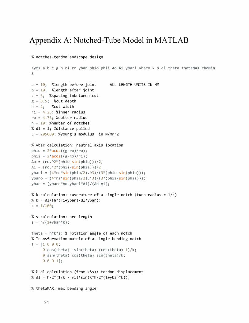
Appendix A: Notched-Tube Model in MATLAB
% notches-tendon endscope design
syms a b c g h ri ro ybar phio phii Ao Ai ybari ybaro k s dl theta thetaMAX rhoMin
S
a = 10; %length before joint ALL LENGTH UNITS IN MM b = 10; %length after joint c = 6; %spacing inbetween cut g = 8.5; %cut depth h = 2; %cut width ri = 4.25; %inner radius ro = 4.75; %outter radius n = 10; %number of notches % dl = 1; %distance pulled
E = 205000; %young's modulus in N/mm^2
% ybar calculation: neutral axis location
phio = 2*acos((g-ro)/ro); phii = 2*acos((g-ro)/ri); Ao = (ro. ̂2*(phio-sin(phio)))/2; Ai = (ro. ̂2*(phii-sin(phii)))/2; ybari = (4*ro*sin(phio/2). ̂3)/(3*(phio-sin(phio))); ybaro = (4*ri*sin(phii/2). ̂3)/(3*(phii-sin(phii))); ybar = (ybaro*Ao-ybari*Ai)/(Ao-Ai);
% k calculation: cuverature of a single notch (turn radius = 1/k)
% k = dl/(h*(ri+ybar)-dl*ybar);
k = 1/100;
% s calculation: arc length
s = h/(1+ybar*k);
theta = n*k*s; % rotation angle of each notch % Transformation matrix of a single bending notch
T = [1 0 0 0; 0 cos(theta) -sin(theta) (cos(theta)-1)/k; 0 sin(theta) cos(theta) sin(theta)/k; 0 0 0 1];
% % dl calculation (from k&s): tendon displacement
% dl = h-2*(1/k - ri)*sin(k*h/2*(1+ybar*k));
% thetaMAX: max bending angle
54

thetaMAX = n*h/(ro+ybar);
% rhoMIN: minimum radius of curvature
rhoMIN = ro+(n-1)*c/thetaMAX;
% S: approximate circular arc length
S = n*(ro*h/(ro+ybar)+c)-c;
% max strain at outer wall
esp = k*(ro-ybar)/(1+ybar*k);
% max stress
sigma = E * esp;
sGPA = sigma/1000; %max stress in GPA
55

Appendix B: Test Fixture Arduino Code
//Global Variables int xStep = 2; int xDir = 5; int xLim = 9; int yStep = 3; int yDir = 6; int yLim = 10; int zStep = 4; int zDir = 7; int zLim = 11; void setup() { // put your setup code here, to run once: //Serial.begin(9600); pinMode(xStep, OUTPUT); pinMode(xDir, OUTPUT); pinMode(xLim, INPUT); pinMode(yStep, OUTPUT); pinMode(yDir, OUTPUT); pinMode(yLim, INPUT); pinMode(zStep, OUTPUT); pinMode(zDir, OUTPUT); pinMode(zLim, INPUT); digitalWrite(xDir, HIGH); digitalWrite(yDir, HIGH); digitalWrite(zDir, HIGH); delay(4000); } void loop() { //SIDE TO SIDE //Goes UP digitalWrite(xDir, HIGH); digitalWrite(yDir, HIGH); digitalWrite(zDir, HIGH); for (int i = 0; i < 40; i++) { xStepMotor(); zStepMotor(); } delay(1000); //Goes DOWN digitalWrite(xDir, LOW); digitalWrite(yDir, LOW); digitalWrite(zDir, LOW);
56

for (int i = 0; i < 80; i++) { xStepMotor(); zStepMotor(); } delay(1000); //Rotates Shaft rotate(); //Goes UP digitalWrite(xDir, HIGH); digitalWrite(yDir, HIGH); digitalWrite(zDir, HIGH); for (int i = 0; i < 40; i++) { xStepMotor(); zStepMotor(); } delay(1000); } void rotate() { //ROTATE //Goes Clockwise digitalWrite(xDir, LOW); digitalWrite(yDir, LOW); digitalWrite(zDir, LOW); for (int i = 0; i < 200; i++) { yStepMotor(); } delay(1000); //Goes Counterclockwise digitalWrite(xDir, HIGH); digitalWrite(yDir, HIGH); digitalWrite(zDir, HIGH); for (int i = 0; i < 200; i++) { yStepMotor(); } delay(1000); } void xStepMotor() { digitalWrite(xStep,HIGH); delayMicroseconds(500); digitalWrite(xStep,LOW); delayMicroseconds(500);
57

} void yStepMotor() { digitalWrite(yStep,HIGH); delayMicroseconds(2000); digitalWrite(yStep,LOW); delayMicroseconds(2000); } void zStepMotor() { digitalWrite(zStep,HIGH); delayMicroseconds(500); digitalWrite(zStep,LOW); delayMicroseconds(500); }
58

Appendix C: Flowchart of ROS Publisher Program
59

Appendix D: Flowchart of MATLAB Subscriber Program
60