Embed Size (px)
Citation preview

URTeC 1620617
Thermal Shock in Reservoir Rock Enhances the Hydraulic Fracturing of Gas Shales Saeid Enayatpour*1; Tad Patzek2 1,2Center for Petroleum and Geosystems Engineering, The University of Texas at Austin Copyright 2013, Unconventional Resources Technology Conference (URTeC)
This paper was prepared for presentation at the Unconventional Resources Technology Conference held in Denver, Colorado, USA, 12-14 August 2013.
The URTeC Technical Program Committee accepted this presentation on the basis of information contained in an abstract submitted by the author(s). The contents of this
paper have not been reviewed by URTeC and URTeC does not warrant the accuracy, reliability, or timeliness of any information herein. All information is the responsibility
of, and, is subject to corrections by the author(s). Any person or entity that relies on any information obtained from this paper does so at their own risk. The information
herein does not necessarily reflect any position of URTeC. Any reproduction, distribution, or storage of any part of this paper without the written consent of URTeC is
prohibited.
Summary
Thermal shock occurs when a material’s temperature is changed over a short period of time such that
constituent parts of the material deform by different amounts. The deformation of material due to thermal load
can be manifested through strain and stress. As the temperature diffuses from hydraulic fracture into reservoir,
the temperature changes with x coordinate and the stress/strain can be obtained from the Equation (6). Once the
stress at any point exceeds the strength of material, the body fails in one of the three modes of tension,
compression or shear. A thermal load on rock, results in the creation and extension of cracks, crushing the
grains, or sliding the grain interfaces. In this paper we look into the possibility of stimulating the rock matrix
beyond hydraulic fracturing stimulation by cooling down the rock. The physics of temperature reduction in a
solid dictates that when a solid is laterally fixed and undergoes temperature reduction, a thermal stress gradient
is induced in the solid body. In rock, this thermal stress gradient leads to a differential contraction of the rock,
which in turn creates openings, referred to as thermal cracks. We numerically solve the nonlinear gas diffusivity
equation, using finite element method and show that the thermal cracks in rock have the potential to improve
the productivity of wells placed in tight formations by 20%.
Introduction: Thermal fracturing
Injection of cold fluids into reservoir rock, induces thermal cracks. This has been observed in the injection of
cold CO2 into reservoir rock for sequestration purposes and from extensive studies of thermal loading on rock
properties [6–8]. For successful fracturing of rocks using temperature reduction, the following system1
properties play a major role:
Decrease of rock tensile strength by flaws in rock matrix
Rapid application of thermal load, causing a steep temperature gradient
Reduction of thermal conductivity of the rock, its fundamental material property. _________________________________________________________________________________________________________________________________________________________________________________________________________________________________
1The system consists of a cylindrical volume of rock around a horizontal wellbore and coolant. The system interface is a no-deformation
cylindrical boundary some distance from the wellbore.
URTeC 1620617 2
• Confinement of rock. Boundary condition plays a major role as the more confined the rock is, the lesscompliance it exhibits to the load, leading to easier crack initiation.
• Increase of the coefficient of thermal expansion. This is also a fundamental material property and notmuch can be done to change this coefficient.
• Increase of the Young modulus. This parameter exhibits the efficacy of thermal shock in shale. Someshales are extremely stiff such as the Qiongzhush Shale in China with the modulus of elasticity of 60Gpa, which is an order of magnitude larger than the Marcellus shale with the modulus of elasticity of 6Gpa [9]. We will see later that large stiffness can enhance the efficiency of fracturing by cooling downthe rock.
• Decrease of toughness. Fracture toughness, exhibits the level of resistance of a material to brittle rupture.The lower the fracture toughness, the closer-to-brittle the fracture could be and the less energy is requiredfor rupturing the rock.
It can be concluded from the above properties of rock that the facility of thermal fracture is mainly pro-portional to the modulus of elasticity and coefficient of thermal expansion and inversely proportional to thethermal conductivity and tensile strength of rock. Here we are discussing equilibrium fracture and its imposeddisplacement. We basically impose thermal shrinkage on a solid (rock), which is laterally confined. We are nottalking about how fast the fracture propagates, rather we are interested in seeing at what level of temperaturereduction the hot reservoir rock starts to develop thermal cracks.
Fracture initiation and propagation
Without loss of generality, many of the concepts of fracture mechanics can be applied to all cases in which anopening in rock extends in size, regardless of applied load. The main types of loads for fracture creation arethe internal fracture fluid pressure and the external tensile stress. Here we go over only a few concepts to setthe scene for understanding the materials described in this article.
The most important property of a rock relevant to fracturing is toughness. In order to understand whattoughness means, one should understand two rock properties, its strength and ductility. Figure 1 explainsthese three properties. In a tensile experiment, a load T is applied to a component such as a rod of originallength L and cross sectional area A and the rod deforms axially to increase the length by ∆L. Strain isdefined as ε = ∆L/L and stress is defined as σ = T/A. Ductility is the ability of material to undergo largestrains and strength is the ability of material to undergo large strains before failure. Toughness depends onthese two properties and it can be calculated as the area under the stress-strain curve or energy dissipated byunit volume of material. Temperature, rate of loading, and existence of voids and cracks could influence thetoughness of a material. For example a rock which remains intact under a static load could fracture under adynamic load.

URTeC 1620617 3
Figure 1: Definition of strength, ductility and toughness
Fracture mechanics started with the works of Inglis [5] and Griffith [2]. Inglis studied stresses around a crackand found out that the stress at the crack tip of an elliptical crack is a function of the curvature of the cracktip and the size of the crack. Griffith showed that when the size of flaws in a solid material increases, the levelof stress before failure decreases. Their studies led to the following relation (1) for designing a componentwhich has flaws or cracks.
KI < KIC(1)
in which, KI is the stress intensity factor which is a function of the applied load and the geometry of crack andKIC
is the fracture toughness which is a function of material properties. As KI gets closer to KIC, unstable
fracture occurs. The fracture toughness KICis in the range of 1 − 5 MPa
√m for sandstones and about 2
MPa√
m for siltstones and mudstones.
Theory and Method
Injection of cold fracturing fluid into reservoir rock, induces thermal fractures perpendicular to hydraulic frac-ture. Figure 2 shows the thermal cracks of depth d perpendicular to hydraulic fracture in a horizontal wellborein a tight formation. Hydraulic fractures tend to grow normal to the minimum horizontal stress, Shmin. Asthe cold fluid is injected into the fractures, the transient heat diffusion causes the heat to be transferred intothe hydraulic fracture as it is colder. This heat transfer, cools down the zone neighboring the fracture andthe rock shrinks parallel to hydraulic fracture length. Since the reservoir rock is confined, thermal stresses arecreated in rock, leading to thermal cracks. Here we are looking at the physics behind this phenomenon andcome up with a formulation of a model to obtain the depth d along x-axis, distance b, and width t of thermalcracks.
Figure 2 also shows that the thermal cracks have to open against the maximum in-situ horizontal stressSHmax. As we see from numerical simulations, these thermal cracks do not extend far from hydraulic fractureface, hence, we can assume these cracks as straight fractures. This observation can justify that as the thermalcracks open, they do not interfere with heat transfer in x-direction.

URTeC 1620617 4
Figure 2: Thermal fractures created perpendicular to the hydraulic fracture
Similar studies [1, 3] on thermal fracturing in ceramic and glass, indicate that the average spacing of thermalcracks is expected to be roughly proportional to their lengths, i.e., b ∝ d. Figure 3 shows the thermal shockcrack pattern on a glass ceramic slab. It can be observed that the length of cracks is roughly proportionalto the spacing of cracks, i.e., the smaller the cracks the shorter apart and the larger the cracks, the furtherapart they are. Due to close material properties of shale and ceramic, we make use of this observation to comeup with sized b and t. The material properties reported for ceramic of the test [1] are: Fracture toughness,KIC = 1.89 MPa
√m; coefficient of thermal expansion, α = 1.15 × 10⁻⁵ K−1; and Young’s modulus, E = 60
GPa. These properties characterize shales; therefore, we expect to see the same pattern of thermal cracks inshale.
Figure 3: Thermal shock crack pattern on a glass ceramic slab [1]. Faces A and C were quenched at ∆T = 300K in water while faces B were kept thermally isolated.
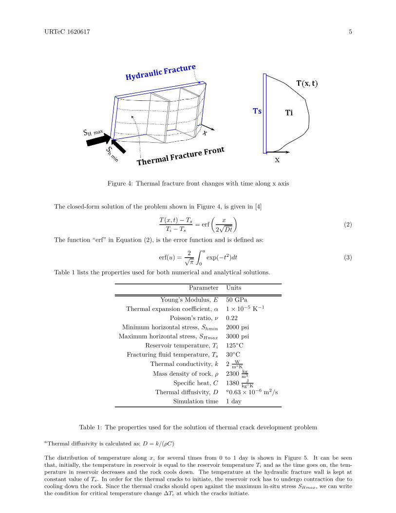
To get an insight on the efficiency of the thermal crack creation during hydraulic fracturing, we solve the 1Dheat conduction in a semi-infinite solid medium shown in Figure 4, numerically. The results are then comparedto analytical heat diffusion solution, Figure 8. We assume that the diffusion of heat from the reservoir to thecold fracturing fluid is conducted along x axis and the fracture side (half-space), is an infinite medium.
URTeC 1620617 5
Figure 4: Thermal fracture front changes with time along x axis
The closed-form solution of the problem shown in Figure 4, is given in [4]
T (x, t) − Ts
Ti − Ts
= erf
(
x
2√
Dt
)
(2)
The function “erf” in Equation (2), is the error function and is defined as:
erf(u) =2
√π
∫ u
0
exp(−t2)dt (3)
Table 1 lists the properties used for both numerical and analytical solutions.
Parameter Units
Young’s Modulus, E 50 GPa
Thermal expansion coefficient, α 1 × 10⁻⁵ K−1
Poisson’s ratio, ν 0.22
Minimum horizontal stress, Shmin 2000 psi
Maximum horizontal stress, SHmax 3000 psi
Reservoir temperature, Ti 125◦C
Fracturing fluid temperature, Ts 30◦C
Thermal conductivity, k 2 Wm◦K
Mass density of rock, ρ 2300 kgm3
Specific heat, C 1380 Jkg◦K
Thermal diffusivity, D a0.63 × 10−6 m2/s
Simulation time 1 day
Table 1: The properties used for the solution of thermal crack development problem
aThermal diffusivity is calculated as; D = k/(ρC)
The distribution of temperature along x, for several times from 0 to 1 day is shown in Figure 5. It can be seenthat, initially, the temperature in reservoir is equal to the reservoir temperature Ti and as the time goes on, the tem-perature in reservoir decreases and the rock cools down. The temperature at the hydraulic fracture wall is kept atconstant value of Ts. In order for the thermal cracks to initiate, the reservoir rock has to undergo contraction due tocooling down the rock. Since the thermal cracks should open against the maximum in-situ stress SHmax, we can writethe condition for critical temperature change ∆Tc at which the cracks initiate.

URTeC 1620617 6
Thermal strain is proportional to the coefficient of thermal expansion and the change of temperature, in other words,
εthermal = α∆T (4)
The deformation of shale is assumed to be linear elastic and the failure is known to be brittle. Also, the component ofthe normal stress of a solid body due to thermal changes, in a linear elastic material can be calculated as
σthermal = Eεthermal = Eα∆T (5)
The thermal stress at any point x in our 1D semi-infinite heat conduction problem is then
σ(x, t) = Eα[Ti − T (x, t)] (6)
Equation (6) is written for the plane stress condition and due to the effect of Poisson’s ration, for the plane straincondition, it should be modified to
σ(x, t) = E(1 + ν)α[Ti − T (x, t)] (7)
When the stress in Equation (6) exceeds the maximum in-situ stress SHmax, thermal cracks develop. Therefore, wecan write the following condition for the initiation of thermal cracks:
E(1 + ν)α[Ti − T (x, t)] > SHmax (8)
and the critical cooling down temperature for the initiation of thermal cracks, which is equal to Ti − T (x, t), can becalculated as
∆Tc >SHmax
E(1 + ν)α(9)
The value of critical cooling down for the case of the problem we simulated is shown in Figure 5. Equation (6) exhibitsan important relation in thermal fracturing of rocks in which the required cooling down for cracks to develop is shownto be a function of rock thermal and strength properties and reservoir condition. It also shows that, the shallower thereservoir, the more efficient the process of thermal fracturing, as ∆Tc will be smaller. One of the great advantagesof inducing thermal shock in rocks is that, ∆Tc will be smaller as the modulus of elasticity of rock gets larger. Forinstance, thermal fracturing could be utilized to create thermal fractures for shales with very large modulus of elasticity,where the fracturing by fluid injection is hard. These openings could serve as seeds for easier and more frequent fractureinitiation points as the fluid injection goes on.
0 0.5 1 1.520
40
60
80
100
120
140
x (m)
T(x
,t) (° C
)
Ti=125 (°C)
Ts=30 (°C)
∆Tc=35.1 (°C)
Ti=125 (°C)
Ts=30 (°C)
∆Tc=35.1 (°C)
Ti=125 (°C)
Ts=30 (°C)
∆Tc=35.1 (°C)
Ti=125 (°C)
Ts=30 (°C)
∆Tc=35.1 (°C)
Ti=125 (°C)
Ts=30 (°C)
∆Tc=35.1 (°C)
Figure 5: Distribution of temperature in 1D along the x-direction.

URTeC 1620617 7
Thermal fracture growth
The length of a fracture plays a significant rule in calculation of the stress intensity factor KI , as a result we areinterested to look into the extension of thermal fractures with time. In order to do this, let’s add and subtract Ti tothe numerator of the Equation (2) and obtain Ti − T (x, t) as
Ti − T (x, t) =
[
(Ti − Ts)erfc
(
x
2√
Dt
)]
(10)
The function “erfc” in Equation (10), is the complementary error function and is defined as:
erfc(u) = 1 − erf(u) =2√π
∫
∞
u
exp(−t2)dt (11)
Now let’s insert [Ti − T (x, t)] from Equation (10) into Equation (8) and change the inequality sign to the equality signfor the onset of crack initiation. By doing this, we get
E(1 + ν)α
[
(Ti − Ts)erfc
(
d
2√
Dt
)]
= SHmax (12)
Notice that x, the coordinate of crack tip is replaced with d, the thermal crack length. Solving Equation (12) for d andwe get
d = (2√
Dt)erfc−1
[
SHmax
E(1 + ν)α(Ti − Ts)
]
(13)
Figure 6 shows the extension of fracture length with time. It can be seen that the length of cracks are not very largeeven after 1 day of cooling down, nevertheless, the creation of such cracks, generate weakness notches for hydraulicfracturing.
0 500 1000 15000
1
2
3
4
5
6
7
Time (min)
d (in
)
Figure 6: The extension of thermal crack length with time. See Figure 2 for the definition of depth d.
Results
As we continue to develop this model, we will be using the closed-form solution to come up with the geometry ofthermal cracks. To make sure about the accuracy of the model, we compare the analytical model with the numericalsolution.
The governing equations of heat transfer in rock are:
1. Equilibrium of forces:∇ · σ = 0 (14)
as deformation along x does not affect the heat diffusion in the x-direction, the boundary conditions for the forceequilibrium equation are fixed.

URTeC 1620617 8
2. Heat transfer equation: In absence of convection and source term, the heat transfer equation is
ρCp
∂T
∂t= ∇ · (k∇T ) (15)
We have solved the coupled system of Equations (14) and (15) using a finite element method and Figure 7 shows theresults of heat diffusion after 1 day. It can be seen that the rock cools down to the depth of 0.5m from the face ofhydraulic fracture. However, to find the rock volume affected by thermal shock, we need to find the depth at whichtemperature decreases by the critical value ∆Tc. This is what we did in Figure 5, where we show that to attain∆Tc, we should find the coordinate x at the intersection of the temperature profiles and the horizontal dashed line,which is the locus of points where the temperature has dropped to Ti − ∆Tc. Figure 7 shows the numerical solution ofEquations (14) and (15).
Figure 7: The numerical solution of temperature distribution in 1D.
Now, let’s compare the numerical result with the closed-form solution. It can be seen that numerical simulation of thiscoupled heat transfer process in rock is in agreement with mathematical closed-form solution. Therefore, we continueto obtain the other parameters of thermal crack, b and t, using the closed-form solution and whenever need arises toconfirm the accuracy of solution, we use numerical simulation. Figure 8 shows the comparison between closed-formand numerical solution.
0 0.5 1 1.520
40
60
80
100
120
140
x (m)
T(x
,t=1
day)
(° C)
Closed−formNumerical
Figure 8: The comparison between closed-form and numerical solution of temperature distribution in 1D

URTeC 1620617 9
Application
Production from the low permeability formations relies on connectivity of flow pathways. Therefore any process thatincreases this connectivity, also enhances productivity. Thermal shock is one such method for increasing connectivityby extending thermal cracks and connecting them to a network of natural fractures. The simulations show that thermalshock initiates thermal cracks, which open against the maximum in-situ horizontal stress. These cracks do not initiallyextend far from the face of the hydraulic fractures; however, they can be extended as the fracturing fluid is injectedinto them. How far the thermal cracks extend, is a function of the strength of rock, flow properties of reservoir rockand the rate of loading. We are studying the propagation of thermal cracks and the results will be presented in thefuture.
We have simulated gas flow in a fractured horizontal well placed in a low permeability formation. The hydraulicfractures are further stimulated by thermal shocks induced by injection of a cold fracturing fluid. Initially many smallthermal cracks are created, however only a few of them can grow far away from the hydraulic fracture. In our simula-tions, we have assumed that only one of the thermal cracks extends far enough to intersect natural fractures. In theabsence of an analytical solution for flow through the complicated geometry of fractures, numerical simulation is usedto obtain the cumulative recovery.
We assume a single phase gas flow in a 1 µd permeability formation. The boundary and well pressures are 3500and 500 psi and production is simulated for 30 years. Figure 9 are the plan views of the pressure distribution af-ter 5 years for the case of no thermal cracks (a) and the case of with thermal cracks (b). The pressures are in psiand the dimensions of reservoir and fractures are shown in meters. The white arrows depict the Darcy’s velocity vectors.
It should be noted that in the case (b), only one of the cracks has extended to intersect natural fractures. In re-ality, due to the presence of a network of natural fractures, more than one crack has the potential to grow and connectto existing fractures. Growth of multiple thermal cracks improves the productivity relative to that shown in Figure 9(c).

URTeC 1620617 10
(a) Pressure distribution for stimulation with hydraulic fractures(t = 5 years)
(b) Pressure distribution for stimulation with hydraulic andthermal fractures (t = 5 years)
0 5 10 15 20 25 300
3
6
9
12x 10
8
Cum
ulat
ive
prod
uctio
n (s
cf)
Time (year)
0 5 10 15 20 25 300
40
80
120
160
Rec
over
y im
prov
emen
t (%
)
No thermal cracksThermal cracks activatedPercent Improvement in Recovery
(c) Recovery improvement due to thermal cracks
Figure 9: Pressure distribution and recovery improvement as a result of thermal cracks
Conclusions
• Fluid production from the low permeability formations depends on the connectivity of natural and inducedfractures. We have shown that a thermal shock during hydraulic fracturing can create small cracks, which mightextend further to intersect natural fractures or be extended by subsequent hydrofracturing.
• For the case of gas production presented in this work, in the first 5 years, production enhancement due to thermalcracks declines from 150% to 20% and remains at 20% thereafter.
• Stiffer rocks, i.e., rocks with larger moduli of elasticity, are easier to fracture by cooling down the rock. This canbe observed from Equation (9).
Aknowledgement
We would like to acknowledge the financial support from a gift by Chevron to Professor T. W. Patzek.
URTeC 1620617 11
References
[1] Hans-Achim Bahr, Hans-Jürgen Weiss, Ute Bahr, Martin Hofmann, Gottfried Fischer, Stefan Lampenscherf, andHerbert Balke. Scaling behavior of thermal shock crack patterns and tunneling cracks driven by cooling or drying.Journal of the Mechanics and Physics of Solids, 58:1411–1421, 2010.
[2] A.A. Griffith. The phenomena of rupture and flow in solids. Philosophical Transactions of the Royal Society ofLondon, 221:163–198, 1921.
[3] H.J. Weiss H.A. Bahr, G. Fischer. Thermal-shock crack patterns explained by single and multiple crack propagation.Journal of Materials Science, 21:2716–2720, 1986.
[4] Frank P. Incropera and David P. DeWitt. Introduction to Heat Transfer. Wiley, 2 edition, 1990.
[5] C. E. Inglis. Stresses in a plate due to the presence of cracks and sharp corners. Spring Meetings of the Fifty-fourthSession of the Institution of Naval Architects, pages 219–241, 1913.
[6] G. Izadi and D. Elsworth. The effects of thermal stress and fluid pressure on induced seismicity during stimulationto production within fractured reservoirs. doi:10.1111/ter.12046, 2013.
[7] G.M. Keaney, C. Jones, and P. Meredith. Thermal damage and the evolution of crack connectivity and permeabilityin ultra-low permeability rocks. American Rock Mechanics Association, 2004.
[8] K. M. Kim and J. Kemeny. Effect of thermal shock and rapid unloading on mechanical rock properties. AmericanRock Mechanics Association, 2009.
[9] Hon C. Lau and Meng Yu. Production technology challenges of tight and shale gas production in china. InternationalPetroleum Technology Conference, 2013. IPTC 17096.