Embed Size (px)
Citation preview

LAB-1 PROBLEM #1: CONSTANT VELOCITY MOTION
These laboratory instructions may be unlike any you have seen before. You will not find worksheets or step-by-step instructions. Instead, each laboratory consists of a set of problems that you solve before coming to the laboratory by making an organized set of decisions (a problem solving strategy) based on your initial knowledge. The instructions are designed to help you examine your thoughts about physics. These labs are your opportunity to compare your ideas about what "should" happen with what really happens. The labs will have little value in helping you learn physics unless you take time to predict what will happen before you do something. While in the laboratory, take your time and try to answer all the questions in this lab manual. In particular, the exploration questions are important to answer before you make measurements. Make sure you complete the laboratory problem, including all analysis and conclusions, before moving on to the next one.
Since this design may be new to you, this first problem contains both the instructions to explore constant velocity motion and an explanation of the various parts of the instructions. The explanation of the instructions is in this font and is preceded by the double, vertical lines seen to the left.
Why are we doing this lab problem? How is it related to the real world? In the lab instructions, the first paragraphs describe a possible situation that raises the problem you are about to solve. This emphasizes the application of physics in solving real-world problems.
To earn some extra money, you have taken a job as a camera operator for the Minneapolis Grand Prix automobile race. Since the race will be simulcast on the Internet, you will be using a digital video camera that stores the images directly on a computer. You notice that the image is distorted near the edges of the picture and wonder if this affects the measurement of a car’s speed from the video image. You decide to model the situation using a toy car, which moves at a constant velocity.
? Does the measured speed of a car moving with a constant velocity depend on the position of the car in a video picture?
The question, framed in a box and preceded by a question mark, defines the experimental problem you

LAB-1 PROBLEM #1: CONSTANT VELOCITY MOTION
are trying to solve. You should keep the question in mind as you work through the problem.
EQUIPMENT
To make a prediction about what you expect to happen, you need to have a general understanding of the apparatus you will use before you begin. This section contains a brief description of the apparatus and the kind of measurements you can make to solve the laboratory problem. The details should become clear to you as you use the equipment.
For this problem, you will use a motorized toy car, which moves with a constant velocity on an aluminum track. You will also have a stopwatch, a meter stick, a video camera and a computer with a video analysis application written in LabVIEW (described in Appendix D) to help you analyze the motion. In the computer the LabVIEW application programs include VIDEOPLAYER and VIDEOTOOL.
PREDICTION
Everyone has his/her own "personal theories" about the way the world works. One purpose of this lab is to help you clarify your conceptions of the physical world by testing the predictions of your personal theory against what really happens. For this reason, you will always predict what will happen before collecting and analyzing the data. Your prediction should be completed and written in your lab journal before you come to lab. The “Method Questions” in the next section are designed to help you determine your prediction and should also be completed before you come to lab. This may seem a little backwards. Although the prediction question is given before the method questions, you should complete the method questions before making the prediction. The prediction question is given first so you know your goal.
Spend the first few minutes at the beginning of the lab session comparing your prediction with those of your partners. Discuss the reasons for any differences in opinion. It is not necessary that your predictions are
2

LAB-1 PROBLEM #1: CONSTANT VELOCITY MOTION
correct, but it is necessary that you understand the basis of your prediction.
How would each of the graphs of position-versus-time, velocity-versus-time, and acceleration-versus-time show a distortion of the position measurement? Sketch these graphs to illustrate your answer. How would you determine the speed of the car from each of the graphs? Which method would be the most sensitive technique for determining any distortions? Appendix B might help you answer this question.
Sometimes, as with this problem, your prediction is an "educated guess" based on your knowledge of the physical world. There is no way to calculate an exact answer to this problem. For other problems, you will be asked to use your knowledge of the concepts and principles of physics to calculate a mathematical relationship between quantities in the experimental problem.
METHOD QUESTIONS
Method Questions are a series of questions intended to help you solve the experimental problem. They either help you make the prediction or help you plan how to analyze data. Method Questions should be answered and written in your lab journal before you come to lab.
To determine if the measured speed is affected by distortion, you need to think about how to measure and represent the motion of an object. The following questions should help with the analysis of your data.
1. How would you expect an instantaneous velocity-versus-time graph to look for an object moving with a constant velocity? Make a rough sketch and explain your reasoning. Write down the equation that describes this graph. If this equation has any constant quantities in it, what are the units of those constant quantities? What parts of the motion of the object does each of these constant quantities represent? For a toy car, what do you estimate should be the magnitude of those quantities? How would a distortion affect this graph? How would it
3

LAB-1 PROBLEM #1: CONSTANT VELOCITY MOTION
affect the equation that describes the graph? How will the uncertainty of your position measurements affect this graph? How might you tell the difference between uncertainty and distortion?
2. How would you expect a position-versus-time graph to look for an object moving with a constant velocity? Make a rough sketch and explain your reasoning. What is the relationship between this graph and the instantaneous velocity versus time graph? Write down the equation that describes this graph. If this equation has any constant quantities in it, what are the units of those constant quantities? What parts of the motion of the object does each of these constant quantities represent? For a toy car, what do you estimate should be the magnitude of those quantities? How would a distortion affect this graph? How would it affect the equation that describes the graph? How will the uncertainty of your position measurements affect this graph? How might you tell the difference between uncertainty and distortion?
3. How would you expect an instantaneous acceleration-versus-time graph to look for an object moving with a constant velocity? Make a rough sketch and explain your reasoning. Write down the equation that describes this graph. If this equation has any constant quantities in it, what are the units of those constant quantities? What parts of the motion of the object does each of these constant quantities represent? For a toy car, what do you estimate should be the magnitude of those quantities? How would a distortion affect this graph? How would it affect the equation that describes the graph? How will the uncertainty of your position measurements affect this graph? How might you tell the difference?
EXPLORATION
This section is extremely important—many instructions will not make sense, or you may be lead astray, if you do not take the time to carefully explore your experimental plan.
4

LAB-1 PROBLEM #1: CONSTANT VELOCITY MOTION
In this section you practice with the apparatus before you make time-consuming measurements which may not be valid. This is where you carefully observe the behavior of your physical system, before you begin making measurements. You will also need to explore the range over which your apparatus is reliable. Remember to always treat the apparatus with care and respect. Your fellow students in the next lab section will need to use the equipment after you are finished with it. If you are unsure about how the apparatus works, ask your lab instructor.
Most apparatus has a range in which its operation is simple and straightforward. This is its range of reliability. Outside of that range, complicated corrections need to be applied. You can quickly determine the range of reliability by making qualitative observations at what you consider to be the extreme ranges of your measurements. Record your observations in your lab journal. If you observe that the apparatus does not function properly for the range of quantities you were considering measuring, you can modify your experimental plan before you have wasted time taking an invalid set of measurements.
The result of the exploration should be a plan for doing the measurements that you need. Record your measurement plan in your journal.
Place one of the metal tracks on your lab bench and place the toy car on the track. Turn on the car and observe its motion. Determine if it actually moves with a constant velocity. Use the meter stick and stopwatch to determine the speed of the car.
Turn on the video camera and look at the motion as seen by the camera on the computer screen. Go to Appendix D for instructions about using the video recorder.
Do you need to focus the camera to get a clean image? How do the room lights affect the image? Which controls help sharpen the image? Record your camera adjustments in your lab journal.
Move the position of the camera closer to the car. How does this affect the video image on the screen? Try moving it farther away. Raise the height of the camera tripod. How does this affect the image? Decide where you want to place the camera to minimize the distortion.
5

LAB-1 PROBLEM #1: CONSTANT VELOCITY MOTION
Practice taking a video of the toy car. Looking at the video frame by frame allows you to check whether the computer has missed any frames (the motion should be smooth). The capacity of the computer to take in all of the data from the video camera depends on the amount of data. If your computer is dropping too many frames, you will not have enough data to analyze. You can minimize the number of frames dropped by decreasing the amount of data in the video picture by adjusting the picture size and keeping the picture as feature free as possible. Check out these effects. Write down the best situation for taking a video in your journal for future reference. You will be doing a lot of this. When you have the best movie possible, save it and open the video analysis application.
Make sure everyone in your group gets the chance to operate the camera and the computer.
MEASUREMENT
Now that you have predicted the result of your measurement and have explored how your apparatus behaves, you are ready to make careful measurements. To avoid wasting time and effort, make the minimal measurements necessary to convince yourself and others that you have solved the laboratory problem.Measure the speed of the car using a stopwatch as it travels a known distance. How many measurements should you take to determine the car’s speed? (Too few measurements may not be convincing to others, too many and you may waste time and effort.) How much accuracy do you need from your meter stick and stopwatch to determine a speed to at least two significant figures? Make the number of measurements you need and record them in a neat and organized manner so that you can understand them a month from now if you must. Also make sure to record precisely how you make these measurements. Some future lab problems will require results from earlier ones.Take a video of the motion of the car to determine its speed. Measure some object you can see in the video
6

LAB-1 PROBLEM #1: CONSTANT VELOCITY MOTION
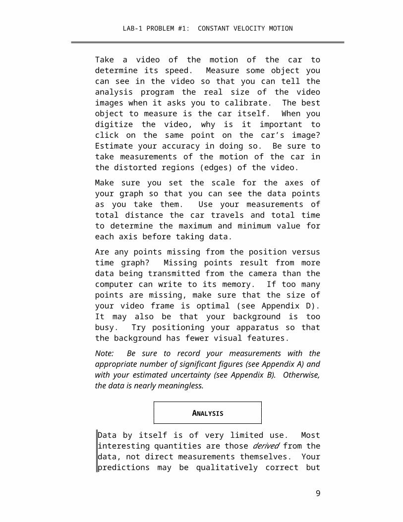
so that you can tell the analysis program the real size of the video images when it asks you to calibrate. The best object to measure is the car itself. When you digitize the video, why is it important to click on the same point on the car’s image? Estimate your accuracy in doing so. Be sure to take measurements of the motion of the car in the distorted regions (edges) of the video.Make sure you set the scale for the axes of your graph so that you can see the data points as you take them. Use your measurements of total distance the car travels and total time to determine the maximum and minimum value for each axis before taking data. Are any points missing from the position versus time graph? Missing points result from more data being transmitted from the camera than the computer can write to its memory. If too many points are missing, make sure that the size of your video frame is optimal (see Appendix D). It may also be that your background is too busy. Try positioning your apparatus so that the background has fewer visual features.Note: Be sure to record your measurements with the appropriate number of significant figures (see Appendix A) and with your estimated uncertainty (see Appendix B). Otherwise, the data is nearly meaningless.
ANALYSIS
Data by itself is of very limited use. Most interesting quantities are those derived from the data, not direct measurements themselves. Your predictions may be qualitatively correct but quantitatively very wrong. To see this you must process your data.
Always complete your data processing (analysis) before you take your next set of data. If something is going wrong, you shouldn't waste time taking a lot of useless data. After analyzing the first data, you may need to modify your measurement plan and re-do the measurements. If you do, be sure to record the changes in your plan in your journal.
Calculate the average speed of the car from your stopwatch and meter stick measurements. Determine if the speed is constant within your measurement
7

LAB-1 PROBLEM #1: CONSTANT VELOCITY MOTION
uncertainties. Can you determine the instantaneous speed of your car as a function of time?
Analyze your video to find the instantaneous speed of the car as a function of time. Determine if the speed is constant within your measurement uncertainties. See Appendix D for instructions on how to do video analysis.
Why do you have less data points for the velocity versus time graph compared to the position versus time graph? Use the data tables generated by the computer to explain how the computer generates the velocity graphs.
CONCLUSIONS
After you have analyzed your data, you are ready to answer the experimental problem. State your result in the most general terms supported by your analysis. This should all be recorded in your journal in one place before moving on to the next problem assigned by your lab instructor. Make sure you compare your result to your prediction.
Compare the car’s speed measured with video analysis to the measurement using a stopwatch. How do they compare? Did your measurements and graphs agree with your answers to the Method Questions? If not, why? What are the limitations on the accuracy of your measurements and analysis?Do measurements near the edges of the video give the same speed as that as found in the center of the image within the uncertainties of your measurement? What will you do for future measurements?
8
LAB-3 PROBLEM #2:FORCES IN EQUILIBRIUM
LAB EXPLORATORY PROBLEM #2
ELECTRIC FIELD FROM A DIPOLEYou have a summer job with a bioengineering company that is studying the electric fields generated by underwater life. Your assignment is to test a portable instrument designed to measure electric fields underwater. To find out if it works correctly, you decide to use it to determine the electric field created by a simple pattern of charged objects. You create a two-dimensional dipole field by giving two parallel metal rods opposite charges with a battery while their tips are immersed in a thin layer of water. You then measure the electric field in the water.
? What is the pattern of the electric field created by the tips of two metal rods with opposite charge in a tray of water?
EQUIPMENT
You will be using the water-tray setup described in Appendix D. There is a coordinate grid attached to the bottom of the tray. Two brass rods (electrodes) stand upright with their tips in the water tray and connected to opposite terminals of a battery or power supply. The electric field probe is connected to a digital multimeter (DMM) set to read volts. You will also have the EM Field program.
rods
Overhead view of water tray for this
problem.
PREDICTION
Page 9

Based on your knowledge of the strength of the electric force, sketch a map of the electric field created in a plane perpendicular to two parallel metal rods with opposite charges. Where do you think the electric field will be the strongest? The weakest?
When you get to lab, check your sketch by making a field map of 2D charged rods using the EM Field simulation.
10

METHOD QUESTIONS
1. Draw a picture of the dipole similar to the one shown in the equipment section. Label one of the charged point objects “+” and the other “-”.
2. At a point in space some distance from one charged object, imagine you have another positively charged point object. Draw a vector representing the force on that “imaginary” object. (Remember that if two objects exert a force on a third object, the force on that third object is the vector sum of the force exerted by the two objects.) Make sure the length of your vector is proportional to the force on the "imaginary" object.
3. How does the magnitude of the force on the “imaginary” object depend on its distance from the positively and negatively charged parts of the dipole? Calculate the magnitude for a few points along each axis of symmetry. For other points, you can add the vectors representing forces due to the positive and negative parts of the dipole graphically.
4. Repeat the process at different points until you have a satisfactory map of the electric field in the space surrounding the dipole.
EXPLORATION
Start by setting up the water tray as instructed in Appendix D. For use of the DMM and power supply, see Appendix D.
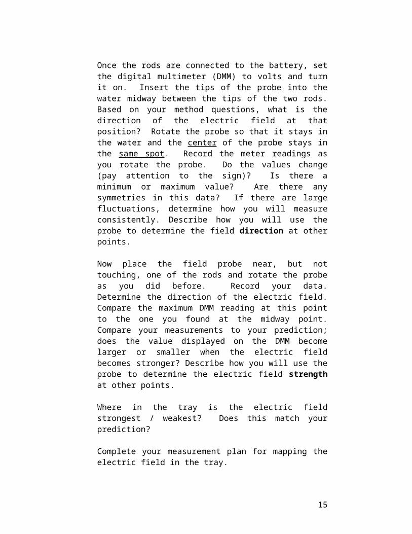
Once the rods are connected to the battery, set the digital multimeter (DMM) to volts and turn it on. Insert the tips of the probe into the water midway between the tips of the two rods. Based on your method questions, what is the direction of the electric field at that position? Rotate the probe so that it stays in the water and the center of the probe stays in the same spot. Record the meter readings as you rotate the probe. Do the values change (pay attention to the sign)? Is there a minimum or maximum value? Are
11

there any symmetries in this data? If there are large fluctuations, determine how you will measure consistently. Describe how you will use the probe to determine the field direction at other points.
Now place the field probe near, but not touching, one of the rods and rotate the probe as you did before. Record your data. Determine the direction of the electric field. Compare the maximum DMM reading at this point to the one you found at the midway point. Compare your measurements to your prediction; does the value displayed on the DMM become larger or smaller when the electric field becomes stronger? Describe how you will use the probe to determine the electric field strength at other points.
Where in the tray is the electric field strongest / weakest? Does this match your prediction?
Complete your measurement plan for mapping the electric field in the tray.
MEASUREMENT
Select a point in the water tray where you wish to determine the electric field. Place the probe in the water at that point and rotate until you have found the direction of the electric field. Record the magnitude and direction of the field at that point by drawing a vector in your lab journal (the length of the vector proportional to the value displayed on the DMM). At each point, take at least two measurements of magnitude and direction to gain a measure of your uncertainty.
Repeat for as many points as needed to check your prediction. When you have taken enough data, your lab journal has a map of the electric field.
CONCLUSION
How does your map compare to your prediction? How does it compare to the simulation program? Where is the field strongest?
12

How do you show this in your map? Where is the field weakest? How do you show this in your map
Lab-1 Problem#3Motion Down an InclineWith an Initial velocity
Because of your physics background, you have a summer job with a company that is designing a new bobsled for the U.S. team to use in the next Winter Olympics. You know that the success of the team depends crucially on the initial push of the team members – how fast they can push the bobsled before
13

they jump into the sled. You need to know in more detail how that initial velocity affects the motion of the bobsled. In particular, your boss wants you to determine if the initial velocity of the sled affects its acceleration down the track. To solve this problem, you decide to model the situation using a cart down an incline.
? Does the acceleration of an object downa ramp depend on its initial velocity?
EQUIPMENT
For this problem you will have a stopwatch, meter stick, a video camera, and a computer with a video analysis application written in LabVIEW. You will also have a cart to roll down a ramp.
For this problem you will slant the ramp at the same angle you used in Problem #2 (Motion Down an Incline) and give the cart a gentle push down the inclined track instead of releasing it from rest.
PREDICTION
From your results for Problem #2, make a rough sketch of the acceleration-versus-time graph for a cart released from rest on an inclined track. On the same graph sketch how you think the acceleration-versus-time graph will look when the cart is given an initial velocity down the track.
Do you think the cart launched down the inclined track will have a larger acceleration, smaller acceleration, or the same acceleration as the cart released from rest? Explain your reasoning.
METHOD QUESTIONS
The following questions may help with your predictions and the analysis of your data.
14
1. Sketch a graph of how would you expect an instantaneous acceleration-versus-time graph to look when the cart moves down the track after an initial push. How does this graph compare to an instantaneous acceleration-versus-time graph for a cart released from rest? Explain your reasoning for each graph. To make the comparison easier, it is useful to draw these graphs next to each other. Write down the equation(s) that best represents each of these graphs. If there are constants in your equation, what kinematic quantities do they represent? How would you determine these constants from your graph?
2. From your acceleration-versus-time graph, draw how you expect an instantaneous velocity-versus-time graph to look for a cart moving down the incline after being pushed. Explain your reasoning and its connection to the acceleration graph. How does this graph compare to a velocity-versus-time graph for a cart released from rest? Use the same scale for your time axes. Write down the equation(s) that best represents each of these graphs. If there are constants in your equation, what kinematic quantities do they represent? How would you determine these constants from your graph? Which graph do you think best represents the velocity of the cart? Change your prediction if necessary.
3. How do you expect a position-versus-time graph to look for a cart moving down the incline after being pushed? Make a rough sketch and explain the connection between this graph and the instantaneous velocity. How does this graph compare to a position-versus-time graph for a cart released from rest? Use the same scale for your time axes. Write down the equation that best represents each of these graphs. If there are constants in your equation, what kinematic quantities do they represent? How would you determine these constants from your graph? Can any of these constants be determined from the constants in the equation representing the velocity versus time graphs? Which graph do you think best represents the position of the cart? Change your prediction if necessary.
15

EXPLORATION
Slant the track at the same angle you used in Problem #2: Motion Down an Incline.
Determine the best way to gently launch the cart down the track in a consistent way without breaking the equipment. BE SURE TO CATCH THE CART BEFORE IT HITS THE END STOP!
Where is the best place to put the camera? Is it important to have most of the motion in the center of the picture? Which part of the motion do you wish to capture? Try taking some videos before making any measurements. Be sure to catch the cart before it collides with the end stop at the bottom of the track.
What is the total distance through which the cart rolls? How much time does it take? These measurements will help you set up the graphs for your computer data taking.
Write down your measurement plan.
Make sure everyone in your group gets the chance to operate the camera and the computer.
MEASUREMENT
Using the plan you devised in the exploration section, make a video of the cart moving down the track at your chosen angle. Make sure you get enough points for each part of the motion to determine the behavior of the acceleration. Don't forget to measure and record the angle (with estimated uncertainty).
Choose an object in your picture for calibration. Choose your coordinate system. Is a rotated coordinate system the easiest to use in this case?
Why is it important to click on the same point on the car’s image to record its position? Estimate your accuracy in doing so.
16

Make sure you set the scale for the axes of your graph so that you can see the data points as you take them. Use your measurements of total distance the cart travels and total time to determine the maximum and minimum value for each axis before taking data.
Are any points missing from the position versus time graph? Missing points result from more data being transmitted from the camera than the computer can write to its memory. If too many points are missing, make sure that the size of your video frame is optimal (see Appendix D). It may also be that your background is too busy. Try positioning your apparatus so that the background has fewer visual features.
ANALYSIS
Choose a function to represent the position versus time graph. How can you estimate the values of the constants of the function from the graph? You can waste a lot of time if you just try to guess the constants. What kinematic quantities do these constants represent?
Choose a function to represent the velocity versus time graph. Compare this function with the function representing the position versus time graph. How can you calculate the values of the constants of this function from the function representing the position versus time graph? Check how well this works. You can also estimate the values of the constants from the graph. Just trying to guess the constants can waste a lot of your time. What kinematic quantities do these constants represent?
From the velocity versus time graph, determine the acceleration as the cart goes down the ramp after the initial push. Use the function representing the velocity versus time graph to calculate the acceleration of the cart as a function of time. Make a graph of that function.
17

As you analyze your video, make sure everyone in your group gets the chance to operate the computer.
18
CONCLUSIONS
Does the acceleration of an object down an inclined ramp depend on its initial velocity?
Did your measurements agree with your initial predictions? Why or why not? What are the limitations on the accuracy of your measurements and analysis?
What will you tell your boss? Does the acceleration of the bobsled down the track depend on the initial velocity the team can give it? Does the velocity of the bobsled down the track depend on the initial velocity the team can give it? State your result in the most general terms supported by your analysis.
19

Lab-1 Problem#2:IMAGE FORMATIOM WITH A PARTIALLY COVERED LENSYour group, consulting for a drug company that hopes to develop new antibiotics, needs to make a video recording of a bacteria specimen under special conditions. These conditions involve light levels too intense for your recording equipment. One of your colleagues suggests partially blocking the microscope lens with a shutter to reduce the light levels for the recording equipment. Others argue that this would block part of the image, so that some parts of the sample would not be recorded.
You decide to test your co-worker's idea with a simplified optical system. You arrange a light source, a lens, and a screen on an optical bench, so that a focused image of the light source appears on the screen.
How does the image change when part of the lens is covered?
EQUIPMENT
For this problem, you will be provided with an optical bench, a convex lens and lens holder, a light source and stand, a screen and holder, a long filament bulb and stand, and a ruler.
PREDICTION
Determine qualitatively how covering part of a convex lens will change the shape and the brightness of the image produced.
METHOD QUESTIONS
It is useful to have an organized problem-solving strategy such as the one outlined in the following questions.
20
1. Draw a fairly large sketch, showing a convex lens and a source of light. The light source should be a vertical arrow that emits light from all parts. Label the lens's focal points, and position the source at a distance from the lens larger than its focal length. Do not indicate the position of the screen, but be sure to leave space so it could be added later.
2. Sketch the paths of two light rays from the top of the light source to the lens, and continue the sketch for each ray on the other side of the lens. (For the rays you choose, simple rules should tell you the path they take after passing through the lens.) Do you expect an image to form in this situation? If so, indicate the position of the image in your sketch. Where should you position the screen in order to see the image?
3. Repeat steps 1 and 2, placing the light source at one of the lens's focal points. Do you expect an image to form in this situation?
4. Repeat steps 1 and 2, placing the light source closer to the lens than its focal point. Do you expect an image to form in this situation?
5. To the sketch of the situation in which an image can be projected onto a screen, add rays that originate at the tip of the arrow and pass through each part of the lens.
6. What will happen to the image of the tip of the arrow if the top half of the lens is covered? Indicate on your diagram which rays could pass through the lens in this situation, and which would be blocked.
7. Repeat the steps above for the point at the bottom of the arrow. What will happen to the image of the bottom of the arrow if the top half of the lens is covered?
8. Side-by-side, sketch the arrow-shaped light source, the image you expect to see when the lens IS NOT covered, and the image you expect to see when the top half of the lens IS covered. Qualitatively
21

compare the sizes, shapes, orientations, and brightnesses of the source and the two images.
EXPLORATION
Experiment to find a way to estimate the focal length of your converging lens. (Hint: Parallel light, as from a distant object, is focused very close to the focal point of a converging lens.)
Position the light source, the convex lens, and a screen on the optics bench so that the principal axis of the lens is aligned with the center of the light source. Adjust their positions along the principal axis so that a focused image appears on the screen. Does the image still exist if the screen is removed? How could you check?
Can you project an image on the screen when the distance p from the light source to the lens is longer than the focal length f? When the light source is closer to the lens than its focal points? What happens when the light source is at the lens’s focal point?
Project a clear image of the light source on the screen. Sketch the shapes of the light source and its image. Is this sketch similar to the one you drew for the method questions? If not, describe the differences.
Cover part of the lens. How does the image change? What changes if you cover different parts of the lens – top, bottom, right, left, middle? What changes if you cover more than half of the lens?
Draw sketches in your lab notebook of what you see on the screen. Indicate which part of the lens was covered for each sketch, as well as the alignment of the image relative to the source. Point out differences among the images formed when different parts of the lens are covered.
Gradually move the cover from the lens to the light source, in such a way that it always blocks about half of the light traveling toward the lens. Describe carefully how the image on the screen changes during this process.
22

ANALYSIS
Did your prediction and method question responses match your observations? If not, how can you change the sketches from the method questions to account for your observations? Can you use the fact that light travels in straight lines, and sketches similar to your (amended) sketches from the method questions, to explain how the image changed as you moved the cover from the lens to the light source?
CONCLUSION
Do your results rule out use of the method proposed by your colleague for reducing light intensity? How is an image formed by a lens? Which rays “participate” in forming the image for a point on an object?
Do your results suggest any advantages that lenses with large diameters have over small lenses? Do your results suggest any advantages of using lenses instead of pinholes to form images, or advantages of using pinholes instead of lenses?
PROBLEM #6: MICROSCOPE
You decide to model your microscopes with a "simple" compound microscope: the "objective lens" -- a strong (short focal length) convex lens placed near the object to be imaged -- and an "eyepiece lens" -- a weaker (longer focal length) convex lens placed near the eye. If the lenses and object are arranged properly, you should see an inverted and enlarged image of the object when you look through the eyepiece lens.
? Is it possible to project an image from a microscope onto a screen?
EQUIPMENT
23

For this problem, you will be provided with an optical bench, a set of convex lenses and two lens-holders, a light source and stand, a transparent grid to place over the light source, a light bulb with vertical filament and a stand, a screen, and rulers.
PREDICTION
Given an objective lens and an eyepiece lens with known focal lengths, determine appropriate positions for the two lenses and for an object to be imaged by a model microscope. Determine the position of the image produced, and predict whether or not that image could be projected on a screen.
METHOD QUESTIONS
It is useful to have an organized problem-solving strategy such as the one outlined in the following questions.
1. Draw a sketch to represent the compound microscope and an object, which meets the following specifications. The two lenses should share the same optical axis. The distance po from the object to the objective lens should be between fo and 2 fo. The position and focal length fe of the “eyepiece” lens will be determined in step 3 below.
2. Draw a ray diagram to show the position and size of the image that produced by the objective lens.
3. In a compound microscope, the image qo
produced by the objective lens is the object pe for the eyepiece lens. The eyepiece lens will be placed so that the image from the objective lens is between the two lenses, and is at a focal point of the eyepiece lens. Add an eyepiece lens to create this arrangement in your sketch.
4. Add rays to show how light from pe will travel after passing through the eyepiece lens. Do the rays converge or diverge? Does the eyepiece lens
24

form a real or virtual image? If so, what is its location?
5. Does the microscope form an image that could be projected on a screen? If so, where should the screen be placed? If not, should it be possible to adjust the microscope so that it could project an image on a screen?
EXPLORATION
Arrange an approximate model of a compound microscope before taking careful measurements. First, estimate the focal lengths of each lens you will use to model the microscope.
Position the light source and a convex lens with short focal length (the “objective”) on the bench. Verify that the principal axis of the lens is parallel to the bench and passes through the center of the source. Find the position of the image formed by the objective lens.
Place another convex lens (the “eyepiece”) in position so that the image formed by the objective lens is approximately at a focal point of the eyepiece lens.
Look through the eyepiece lens. Can you see an image of the light source? Is it inverted or erect? Does it appear to be enlarged? Can you estimate how much the image is enlarged? Can an image be projected onto a screen? What do you observe if you move the eyepiece lens along the principal axis, or if you adjust the position of the light source or objective lens? How can you tell when you have achieved the conditions described in the method questions for a compound microscope?
Try focusing the microscope on the vertical filament light bulb. (The filament is very bright, so you may wish to focus on some other part of the bulb.) Can you focus on different parts of the bulb?
MEASUREMENT
25
Carefully determine the focal length of each lens you will use in the model microscope.
Place the light source and the objective lens at a convenient distance po apart. Following the methods you developed in the exploration, adjust the position of the eyepiece lens until you have achieved the conditions necessary for a compound microscope. Measure and record the relevant positions and focal lengths.
Will the microscope project an image on a screen, or can it be adjusted to do so? If so, measure image positions, magnification, lens positions and light source positions, and describe the image produced.
Repeat this for at least one more values of po.
Repeat, if possible with the same two values of p0, for a second eyepiece lens.
ANALYSIS
For each value of po, compare the observed separation of the two lenses with the expected value, from the methods questions. Can you account for any discrepancies?
Qualitatively, how did the second eyepiece lens change the magnification of the microscope? Why did you (or why didn't you) expect this change?
CONCLUSION
How does the position of the eyepiece depend on the distance po between the object and the objective lens, and on the focal lengths fo and fe of the lenses?
Is it possible to use a microscope to project an image on a screen for observation, without extra optical equipment? Do you support your boss’s claim that it is
26

not possible? If it is possible, explain why or why not you think it could be useful.
LAB-2 Problem#1:MASS AND THE ACCELERATION OF A FALLING BALLYou have a summer job with the National Park Service. Your task is to investigate the effectiveness of spherical canisters filled with fire-retarding chemicals to help fight forest fires. The canisters would be dropped by low-flying planes or helicopters. They are specifically designed to split open when they hit the ground, showering the nearby flames with the chemicals. The canisters could contain different chemicals, so they will have different masses. In order to drop the canisters accurately, you need to know if the motion of the canisters will be different if they contain different chemicals. You decide to investigate the problem by making measurements to determine if the free-fall acceleration of the canisters depends on their mass.
? How does the acceleration of a freely falling object depend on its mass?
EQUIPMENT
For this problem, you will have a collection of balls each with approximately the same diameter. You will also have a stopwatch, a meter stick, a video camera and a computer with a video analysis application written in LabVIEW.
PREDICTION
27
Make a sketch of how you expect the average acceleration-versus-mass graph to look for falling objects with the same size and shape but different masses.
Do you think that the free-fall acceleration increases, decreases, or stays the same as the mass of the object increases? Make your best guess and explain your reasoning.
METHOD QUESTIONS
1. Write down an outline of how you will determine the acceleration of the object from video data.
2. Sketch a graph of acceleration as a function of time for a constant acceleration and next to it one for half of that acceleration. Below those graphs, make graphs for velocity as a function of time and position as a function of time. Write down the equation that best represents each of these accelerations. If there are constants in your equation, what kinematic quantities do they represent? How would you determine these constants from your graph?
3. Make a sketch of the acceleration-versus-time graph you expect for a heavy falling ball. Next to that graph make another one for the acceleration of a ball with one quarter of the mass. Explain your reasoning? Write down the equation that best represents each of these accelerations. If there are constants in your equation, what kinematic quantities do they represent? How would you determine these constants from your graph? How do they differ from your constant acceleration graphs?
4. Write down the relationship between the acceleration and the velocity of an object. How could you write an equation for the velocity in which the acceleration was not constant but changed
28

linearly with time? What do the constant quantities in that equation represent?
5. Use the relationship between the acceleration and the velocity of the ball to construct an instantaneous velocity-versus-time graph for each case from Method Question 3. The connection between the derivative of a function and the slope of its graph will be useful. Write down the equation that best represents each of these velocities. If there are constants in your equation, what kinematic quantities do they represent? How would you determine these constants from your graph? Can any of these constants be determined from the constants in the equation representing the acceleration? Change your prediction if necessary.
6. Write down the relationship between the velocity and the position of the ball. Use that relationship to construct a position-versus-time graph for each case. The connection between the derivative of a function and the slope of its graph will be useful. Write down the equation that best represents each of these positions. If there are constants in your equation, what kinematic quantities do they represent? How would you determine these constants from your graph? Can any of these constants be determined from the constants in the equation representing the velocity? Change your prediction if necessary.
7. Compare your graphs to those for constant acceleration (Method Question 2). What are the differences, if any, that you might observe in your data? The similarities?
EXPLORATION
Review your lab journal from the problems in Lab 1. Position the camera and adjust it for optimal performance. Make sure everyone in your group gets the chance to operate the camera and the computer.
Practice dropping one of the balls until you can get the ball's motion to fill the least distorted part of the screen. Determine how much time it takes for the ball
29

to fall and estimate the number of video points you will get in that time. Are there enough points to make the measurement? Adjust the camera position and screen size to give you enough data points without dropping too many. You should be able to reproduce the conditions described in the Predictions.
Although the ball is the best item to use to calibrate the video, the image quality due to its motion might make this difficult. Instead, you might hold an object of known length in the plane of motion of the ball, near the center of the ball’s trajectory, for calibration purposes. Where you place your reference object does make a difference in your results. Check your video image when you put the reference object close to the camera and then further away. What do you notice about the size of the reference object in the video image? The best place to put the reference object to determine the distance scale is at the position of the falling ball.
Step through the video and determine which part of the ball is easiest to consistently determine. When the ball moves rapidly you may see two images of the ball due to the interlaced scan of a TV camera. You should use the same image for each measurement.Write down your measurement plan.
MEASUREMENT
Measure the mass of a ball and make a video of its fall according to the plan you devised in the exploration section. Make sure you can see the ball in every frame of the video.
Digitize the position of the ball in enough frames of the video so that you have the sufficient data to accomplish your analysis. Make sure you set the scale for the axes of your graph so that you can see the data points as you take them. Use your measurements of total distance the ball travels and total time to determine the maximum and minimum value for each axis before taking data.
30

Complete your data analysis as you go along (before making the next video), so you can determine how many different videos you need to make. Don’t waste time in collecting data you don't need or, even worse, incorrect data. Collect enough data to convince yourself and others of your conclusion.
Repeat this procedure for different balls.
ANALYSIS
Choose a function to represent the position-versus-time graph. How can you estimate the values of the constants of the function from the graph? You can waste a lot of time if you just try to guess the constants. What kinematic quantities do these constants represent?
Choose a function to represent the velocity-versus-time graph. How can you calculate the values of the constants of this function from the function representing the position-versus-time graph? Check how well this works. You can also estimate the values of the constants from the graph. Just trying to guess the constants can waste a lot of your time. What kinematic quantities do these constants represent?
If you cannot get one function to describe your velocity graph in a consistent way, you can try using one function for the first half of the motion and another for the last half. To do this you must go through the video analysis process twice and record your results each time.
From the velocity-versus-time graph determine the acceleration of the ball. Use the function representing the velocity versus time graph to calculate the acceleration of the ball as a function of time. Is the average acceleration different for the beginning of the video (when the object is moving slowly) and the end of the video (when the object is moving fast)?
31

Determine the average acceleration of the object in free fall for each value of its mass and graph this result. Do you have enough data to convince others of your conclusions about your predictions?
CONCLUSION
Did the data support your predicted relationship between acceleration and mass? (Make sure you carefully review Appendix C to determine if your data really supports this relationship.) If not, what assumptions did you make that were incorrect? Explain your reasoning.What are the limitations on the accuracy of your measurements and analysis?Do your results hold regardless of the masses of balls? Would the acceleration of a falling Styrofoam ball be the same as the acceleration of a falling baseball? Explain your rationale. Make sure you have some data to back up your claim. Will the acceleration of a falling canister depend on its mass? State your results in the most general terms supported by your analysis.
32

LAB-3 PROBLEM #2: FORCES IN EQUILIBRIUM
You have a summer job with a research group studying the ecology of a rain forest in South America. To avoid walking on the delicate rain forest floor, the team members walk along a rope walkway that the local inhabitants have strung from tree to tree through the forest canopy. Your supervisor is concerned about the maximum amount of equipment each team member should carry to safely walk from tree to tree. If the walkway sags too much, the team member could be in danger, not to mention possible damage to the rain forest floor. You are assigned to set the load standards.
Each end of the rope supporting the walkway goes over a branch and then is attached to a large weight hanging down. You need to determine how the sag of the walkway is related to the mass of a team member plus equipment when they are at the center of the walkway between two trees. To check your calculation, you decide to model the situation using the equipment shown below.
? How does the vertical displacement of an object suspended on a string halfway between two branches, depend on the mass of that object?
EQUIPMENT
The system consists of a central object, B, suspended halfway between two pulleys by a string. The whole system is in equilibrium. The picture below is similar to the situation with which you will work. The objects A and C, which have the same mass (m), allow you to determine the force exerted on the central object by the string.
33

You do need to make some assumptions about what you can neglect. For this investigation, you will also need a meter stick, two pulley clamps, three mass hangers and a mass set to vary the mass of objects.
P
L
PREDICTION
Calculate the change in the vertical displacement of the central object B as you increase its mass (M). You should obtain an equation that predicts how the vertical displacement of central object B depends on its mass (M), the mass (m) of objects A and C, and the horizontal distance (L) between the two pulleys.
Use your equation to make a graph of the vertical displacement of object B as a function of its mass (M).
METHOD QUESTIONS
To solve this problem it is useful to have an organized problem-solving strategy such as the one outlined in the following questions. You should use a technique similar to that used in Problem 1 (where a more detailed set of Method Questions is given) to solve this problem. You might also find the Problem Solving section 4-6 of your textbook is useful.
1. Draw a sketch similar to the one in the Equipment section. Draw vectors that represent the forces on objects A, B, C, and point P. Use trigonometry to show how the vertical displacement of object B is related to the horizontal distance between the two pulleys and the angle that the string between the two pulleys sags below the horizontal.
2. The "known" (measurable) quantities in this problem are L, m and M; the unknown quantity is the vertical displacement of object B.
34

3. Use Newton's laws to solve this problem. Write down the acceleration for each object. Draw separate force diagrams for objects A, B, C and for point P (if you need help, see your text). What assumptions are you making?Which angles between your force vectors and your horizontal coordinate axis are the same as the angle between the strings and the horizontal?
4. For each force diagram, write Newton's second law along each coordinate axis.
5. Solve your equations to predict how the vertical displacement of object B depends on its mass (M), the mass (m) of objects A and C, and the horizontal distance between the two pulleys (L). Use this resulting equation to make a graph of how the vertical displacement changes as a function of the mass of object B.
6. From your resulting equation, analyze what is the limit of mass (M) of object B corresponding to the fixed mass (m) of object A and C. What will happen if M>2m?
EXPLORATION
Start with just the string suspended between the pulleys (no central object), so that the string looks horizontal. Attach a central object and observe how the string sags. Decide on the origin from which you will measure the vertical position of the object.
Try changing the mass of objects A and C (keep them equal for the measurements but you will want to explore the case where they are not equal).
Do the pulleys behave in a frictionless way for the entire range of weights you will use? How can you determine if the assumption of frictionless pulleys is a good one?
Add mass to the central object to decide what increments of mass will give a good range of values for
35

the measurement. Decide how measurements you will need to make.
MEASUREMENT
Measure the vertical position of the central object as you increase its mass. Make a table and record your measurements.
ANALYSIS
Make a graph of the vertical displacement of the central object as a function of its mass based on your measurements. On the same graph, plot your predicted equation.
Where do the two curves match? Where do the two curves start to diverge from one another? What does this tell you about the system?
What are the limitations on the accuracy of your measurements and analysis?
CONCLUSION
What will you report to your supervisor? How does the vertical displacement of an object suspended on a string between two pulleys depend on the mass of that object? Did your measurements of the vertical displacement of object B agree with your initial predictions? If not, why? State your result in the most general terms supported by your analysis.
What information would you need to apply your calculation to the walkway through the rain forest?
Estimate reasonable values for the information you need, and solve the problem for the walkway over the rain forest.
36

LAB-3 PROBLEM #4: NORMAL AND KINETIC FRICTIONAL
FORCE IYou are working for a company that contracts to test the mechanical properties of different materials of systems. One of the customers wants your group to determine the coefficient of kinetic friction for wood on aluminum.
You decide to measure the coefficient of kinetic friction by graphing the frictional force as a function of the normal force using a wooden block sliding on an aluminum track. The coefficient of kinetic friction is the slope of that graph. Of course, there is measurement uncertainty no matter how you do the measurement. For this reason, you decide to vary the normal force in two different ways to see if you get consistent results. You divide your group into two teams. One team will vary the normal force by changing the angle of incline of the track (Problem #5). Your team will vary the normal force by changing the mass of the block.
? What is the coefficient of kinetic friction for wood on aluminum?
EQUIPMENT
A wooden block slides down an aluminum track, as shown below.
The tilt of the aluminum track with respect to the horizontal can be adjusted. You can change the mass of the wooden block by attaching additional mass on it. Video analysis equipment will allow you to determine the acceleration of the wooden block sliding down the aluminum track. Two wooden blocks, a meter stick, a
Page 37

stopwatch and a mass set are available for this experiment.
38

PREDICTIONS
The coefficient of kinetic friction is the slope of the graph of the kinetic frictional force as a function of normal force. Using the Table of Coefficients of Friction on page 25, sketch a graph of the kinetic frictional force on the block against the normal force on the block.
Explain your reasoning.
METHOD QUESTIONS
To test your prediction you must determine how to calculate the normal force and the kinetic frictional force from the quantities you can measure in this problem. You do not need to know much about friction to make this prediction. It is useful to have an organized problem-solving strategy such as the one outlined in the following questions. You should use a technique similar to that used in Problem 1 (where a more detailed set of Method Questions are given) to solve this problem.1. Make a drawing of the problem situation similar to
the one in the Equipment section. Draw vectors to represent all quantities that describe the motion of the block and the forces on it. What measurements can you make with a meter stick to determine the angle of incline? Choose a coordinate system. What is the reason for using the coordinate system you picked?
2. What measurements can you make to enable you to calculate the kinetic frictional force on the block? What measurements can you make to enable you to calculate the normal force on the block? Do you expect the kinetic frictional force on the wooden block to increase, decrease, or stay the same as the normal force on the wooden block increases? Explain your reasoning.
3. Draw a free-body diagram of the wooden block as it slides down the aluminum track. Draw the acceleration vector for the block near the free-body
39

diagram. Transfer the force vectors to your coordinate system. What angles between your force vectors and your coordinate axes are the same as the angle between the aluminum track and the table? Determine all of the angles between the force vectors and the coordinate axes.
4. Write down Newton’s 2nd Law along each coordinate axis.
5. Using the equations in step 4, determine an equation for the kinetic frictional force in terms of quantities you can measure. Next determine an equation for the normal force in terms of quantities you can measure. In our experiment, the measurable quantities include the mass of the block, the angle of incline and the acceleration of the cart.
EXPLORATION
Find an angle at which the wooden block accelerates smoothly down the aluminum track. Try this when the wooden block has different masses on top of it.
Select an angle and series of masses that will make your measurements most reliable.
MEASUREMENT
Keeping the aluminum track at the same angle, take a video of the wooden block's motion. Keep the track fixed when block is sliding down. Make sure you measure and record that angle. You will need it later.
Repeat this procedure for different block masses to change the normal force. Make sure the block moves smoothly down the incline for each new mass. Make sure every time you use the same surface of the block to contact the track.
Collect enough data to convince yourself and others of your conclusion about how the kinetic frictional force on the wooden block depends on the normal force on the wooden block.
40

ANALYSIS
For each new block mass and video, calculate the magnitude of the kinetic frictional force from the acceleration. Also determine the normal force on the block.
Graph the magnitude of the kinetic frictional force against the magnitude of the normal force, for a constant angle of incline. On the same graph, show your predicted relationship.
CONCLUSION
What is the coefficient of kinetic friction for wood on aluminum? How does this compare to your prediction based on the table?
What are the limitations on the accuracy of your measurements and analysis? Over what range of values does the measured graph match the predicted graph best? Where do the two curves start to diverge from one another? What does this tell you?
If available, compare your value of the coefficient of kinetic friction (with uncertainty) with the value obtained by the different procedure given in the next problem. Are the values consistent? Which way of varying the normal force to measure the coefficient of friction do you think is better? Why?
Table of Coefficients of Friction*
Surfaces s k
Steel on steel 0.74 0.57
Aluminum on steel 0.61 0.47
Copper on steel 0.53 0.36
41

Steel on lead 0.9 0.9
Copper on cast iron 1.1 0.3
Copper on glass 0.7 0.5
Wood on wood 0.25 - 0.5 0.2
Glass on glass 0.94 0.4
Metal on metal (lubricated) 0.15 0.07
Teflon on Teflon 0.04 0.04
Rubber on concrete 1.0 0.8
Ice on ice 0.1 0.03
Wood on Aluminum 0.25-0.3
* All values are approximate.
42

Page 43

LAB-3 PROBLEM#3:MECHANICAL ENERGY AND
TEMPERATURECHANGE
You are running one day when you start thinking about conservation of energy. You know you are reducing your internal chemical energy stored in body fat. You wonder where the energy goes. If you ignore air resistance, which you know can’t always be done when running, you cannot transfer energy to the air. If you consider the time between the start of your run and the end of your run, your kinetic energy does not change since you are not moving at the beginning or end of your run. Later you share your thought with a friend who tells you that energy is transferred out of your body by sweat. You sweat because your body temperature rises. Thus the upshot of running seems to be the conversion of chemical energy stored in your body to an increase in its thermal or internal energy. You know this happens but is that all there is to it?
To test part of this idea, you decide to design a simple mechanical device that allows you to test the biological process of using one form of energy to raise the temperature of an object. One form of energy that is easily measured is mechanical work. If you have a known force exerted on an object for a known distance, you can calculate the energy transferred to that object. Your friend suggests using a frictional force since you know that kind of force raises the temperature of objects. You decide to have a cylindrical object make multiple revolutions about its axis while its surface rubs against another object (a rope) to create this frictional force. Measuring the temperature of the object allows you to calculate it change of internal thermal energy. If all of the mechanical energy transferred to the object by the frictional force becomes internal thermal energy of the object, using conservation of energy you can calculate the temperature change of the object as a function of the
44

frictional force, the distance over which that force is exerted, and the heat capacity of the object. You can check your calculation with the device shown below.
? Calculate the change of temperature of an object as a function of the force exerted on it, the distance over which that force is exerted, and the heat capacity of the object.
EQUIPMENT
Your device consists of an aluminum cylinder attached to a shaft that can be turned with a crank, as shown below. A rope is wrapped a few times around the cylinder so that, as the crank is turned, the friction between the rope and cylinder is just enough to support a heavy block hanging from one end of the rope.
For safety, the other end of the rope is held loosely such that barely any force is exerted on the rope at that end.
Side view Front view
While the cylinder is revolving, the friction between the cylinder and rope is the force holding up the block. An electronic thermometer is embedded into the cylinder. It is read out with a digital multimeter (DMM).
45

A balance, a stopwatch, and ruler are also available. The cylinder is made of aluminum.
PREDICTION
Calculate the change of temperature of the cylinder as a function of the weight of the block, the radius of the cylinder, the number of turns that you crank the cylinder, the specific heat of the cylinder, and the mass of the cylinder. Specify what assumptions are necessary to make this calculation and what additional information is needed.
46

METHOD QUESTIONS
To complete your prediction, it is useful to follow an organized problem-solving procedure, such as the one outlined below:
1. Make a sketch of the situation. On your sketch, label all relevant known and unknown quantities.
2. Write down the general conservation of energy equation. Decide on the most convenient system for this situation. Decide on your initial time and draw what is happening. Decide on your final time and make another drawing of what is happening then. Is any energy being transferred to or from your system between the initial and final times? If so make a drawing that represents this energy transfer. Look at your three drawings that represent the energy state of your system at the initial time, the energy state of your system at the final time, and the energy transfer. Have you represented everything of importance that is happening?
3. Using your three drawings, write down the initial energy of your system, the final energy of your system, and the energy transferred to or from your system. Put these terms into the general conservation of energy equation.
4. Determine the relationship between the friction force between rope and the cylinder and the weight of the block. Explain why you believe this relationship is true.
5. Determine the direction of the frictional force relative to the motion of the rim of the cylinder where it makes contact. Does all of the frictional force transfer energy to the cylinder? Is this energy transfer an input or an output? Explain.
6. Write down the distance that the frictional force of the rope is exerted on the cylinder when the cylinder makes one complete turn. What is this distance if the cylinder makes N turns?
7. Are any other forces exerted on the cylinder? Explain how they affect the energy of the cylinder.
47
Write down any approximations that you think are justified.
8. Write down the relationship between the temperature change of the cylinder and its internal energy change. Look up the specific heat for aluminum.
48

EXPLORATION
Switch the DMM to the Ohms (Ω) setting and connect it to the electronic thermometer (called a thermistor). Check that you get a numerical reading of resistance. Try different scales to determine which is most useful. See Appendix A for instructions about how to use the DMM to measure resistance. Touch the cylinder with your hand to make sure the reading responds to your body temperature.
The relationship between the temperature of the thermistor and its resistance is complex and may be different for different devices. Look at the table of Temperature versus Resistance that is attached to the base of the crank for yours. Make a graph of this table so that you can interpolate between temperature readings with sufficient accuracy. Estimate the current temperature of your cylinder and use your graph to see if the DMM reading is reasonable.
Try holding the block with your hand to give you a feeling for the amount of force necessary to hold the block steady. The block is heavy so always make sure no one’s foot is under it in case it drops.
Practice rotating the aluminum cylinder uniformly so that the block hangs steady several centimeters from the floor. You may have to adjust the amount of rope you have wound around the cylinder. Try not to overlap the rope with itself since you want it to rub against the cylinder. Support the other end of the rope with your hand. Very little force (much less than the weight of the block) should be applied at this end while the crank is being turned.
Watch how the DMM reading changes when you rotate the cylinder to determine how many rotations you will have to make to get a significant temperature change.
Some energy is transferred from the cylinder into the air because of the temperature difference (heat). This energy transfer is difficult to calculate but needs to be represented in your conservation of energy equation. Plan some way of estimating this.
49

Write down your experimental plan.
50
MEASUREMENT
Using your plan, make the necessary measurements. Check your conservation of energy equation and all of the energy terms from the Methods Questions to make sure you have measured everything you need.
Repeat your measurement enough times so that the average of all your measurements gives reliable results.
Make your measurement of the cylinder’s energy transfer to the air for the amount of time this transfer actually takes place during your friction measurement. Since this energy transfer depends on the cylinder temperature, it is important to start the measurement at the right cylinder temperature.
You can take apart the apparatus to measure the properties of the cylinder.
ANALYSIS
From your measurement results, determine the change in the cylinder’s internal energy that you expect from mechanical energy transfer. Compare this to the change of the cylinder’s internal energy directly determined from its temperature change.Compare the size of the measured mechanical energy transferred to the cylinder (work) to your separate measurement of the energy transferred from the cylinder to the air (via heat). Which is larger? Does the heat term make much of a difference in the validity of your measurement? If so make sure you include it in your conservation of energy equation.Use your Prediction equation to calculate the expected temperature change and compare it to the measured temperature change.How do your measured and predicted values compare? Which one is larger? Why?
CONCLUSION
51

Compare your predicted and measured temperature difference. Explain any difference.
Can you estimate the amount of energy you spent after conducting the experiment?
52

MORE LAB-4 EXPLORATORY PROBLEM #2:
COMPLEX CIRCUITS
It is the holiday season once again so you have decided to put up your decorations. You have three strings of decorative lights and only one electrical outlet between the tree and your doorway. To have enough lights to cover the tree, you will need to connect two of your light strings together end to end. The other set of lights will be enough to light up your doorway. You know that you have a few ways of connecting the lights. However, you want to hook up the lights in such a way as to get them all as bright as possible. Before you begin the long process of decorating, you want to make sure that you are using the right set-up to get the brightest lights. So you build a reference circuit and a model of the possible ways of connecting the sets of lights in order to determine which gives the most light. In your model one light bulb represents a light string.
? How can you connect three light bulbs so that all three are as bright as possible?
EQUIPMENT
You will build the three simple circuits shown below out of wires, bulbs, and batteries. Use the accompanying legend to help you build the circuits.
Legend:
light bulb
battery
wire
53

PREDICTION
Rank the brightness of the bulbs A, B, C, D, H, J, K, L, M, and N from the brightest to the dimmest (use the symbol ‘=’ for "same brightness as" and the symbol ‘>’ for "brighter than"). Write down your reasoning.
EXPLORATION
Reference Circuit: Connect Circuit I to use as a reference.
Circuit II: Connect Circuit II. Compare the brightness of bulbs B and C. Compare the brightness of bulbs B and C to bulb D. What can you conclude from this observation about the amount of current through each bulb?
54
Note: Pay attention to large differences you may observe, rather than minor differences that may occur if two "identical" bulbs are, in fact, not identical. How can you test whether minor differences are due to manufacturing irregularities?
How does the brightness of bulbs B and C compare to the brightness of bulb A (Circuit I)? What can you infer about the current at point 2 in Circuit IV and the current at point 1 in Circuit I?
How does the brightness of bulb D compare to the brightness of bulb A (Circuit I)? What can you infer about the current at point 3 in Circuit IV and the current at point 1 in Circuit I?
Describe the flow of current around the entire circuit. What do your observations suggest about the way the current through the battery divides and recombines at junctions where the circuit splits into two parallel branches? How does the current at point 1 in Circuit IV compare with the current at point 1 in Circuit I? Explain any differences.
Circuit III: Connect Circuit III. Compare the brightness of bulbs F and G. Compare the brightness of bulbs F and G to bulb E. What can you conclude from this observation about the amount of current through each bulb?
How does the brightness of bulb E compare to the brightness of bulb A (Circuit I)? What can you infer about the current at point 3 in Circuit II and the current at point 1 in Circuit I?
How does the brightness of bulb E compare to the brightness of bulb A (Circuit I)? What can you infer about the current at point 3 in Circuit II and the current at point t in circuit 1?
Describe the flow of current around the entire circuit. What do your observations suggest about the way the current through the battery divides and recombines at junctions where the circuit splits into two branches? How does the current at point 2 compare with the currents at points 3 and 4?
55

Circuit III: Connect Circuit III. Compare the brightness of the bulbs. What can you conclude from this observation about the amount of current through each bulb?
How does the brightness of bulb H compare to the brightness of bulb A (Circuit I)? What can you infer about the current at point 1 in Circuit III and the current at point 1 in Circuit I?
Circuit IV: Connect Circuit IV. Compare the brightness of the bulbs. What can you conclude from this observation about the amount of current through each bulb?
How does the brightness of bulb L compare to the brightness of bulb A (Circuit I)? What can you infer about the current at point 1 in Circuit IV and the current at point 1 in Circuit I?
CONCLUSION
Rank the actual brightness of the bulbs A, B, C, D, H, J, K, L, M and N. Make sure you have adequately defined your comparisons: “same brightness as”, “brighter than”, and “dimmer than”. How did your prediction compare to your results? Can you use conservation of energy and conservation of current to explain your results?
How will you connect your three strings of lights so that they are all as bright as possible?
56

LAB-5 PROBLEM#6:MEASURING THE MAGNETIC FIELD OF TWO
PARALLEL COILS
You have a part time job working in a laboratory developing large liquid crystal displays that could be used for very thin TV screens and computer monitors. The alignment of the liquid crystals is very sensitive to magnetic fields. It is important that the material sample be in a fairly uniform magnetic field for some crystal alignment tests. The laboratory has two nearly identical large coils of wire mounted so that the distance between them equals their radii. You have been asked to determine the magnetic field between them to see if it is suitable for the test.
? For two large, parallel coils, what is the magnetic field on the axis, as a function of the distance from the middle of the two coils?
EQUIPMENT
Connect two large coils to a power supply so that each coil has the same current. Each coil has 150 turns.
You will have a digital Multimeter (DMM), a compass, a meter stick, and a Hall probe. A computer is used for data acquisition.
x
I I
R R
PREDICTION
Calculate the magnitude of the magnetic field for two coils as a function of the position along their central axis, for the special case
Page 57

where the distance between the coils is the same as the radius of the coils. Use this expression to graph the magnetic field strength versus position along the axis.
METHOD QUESTIONS
1. Draw a picture of the situation showing the direction of the current through each coil of wire. Establish a single convenient coordinate system for both coils.
Label all of the relevant quantities.
2. Select a point along the axis of the two coils at which you will determine an equation for the magnetic field. In the previous problem, you calculated the magnetic field caused by one coil as a function of the position along its axis. To solve this problem, add the magnetic field from each coil at the selected point along the axis. Remember to pay attention to the geometry of your drawing. The origin of your coordinate system for this problem cannot be at the center of both coils at once. Also remember that the magnetic field is a vector.
3. Use your equation to graph the magnetic field strength as a function of position from the common origin along the central axis of the coils. Describe the qualitative behavior of the magnetic field between the two coils. What about the region outside the coils?
EXPLORATION
WARNING: You will be working with a power supply that can generate large electric voltages. Improper use can cause painful burns. To avoid danger, the power should be turned OFF and you should WAIT at least one minute before any wires are disconnected from or connected to the power supply. Never grasp a wire by its metal ends.
Connect the large coils to the power supply with the current flowing in opposite directions in the two coils, using the adjustable voltage.
58

With the compass, explore the magnetic field produced. Be sure to look both between the coils and outside the coils.
Now connect the large coils to the power supply with the current flowing in the same direction in each coil, using the adjustable voltage. With the compass, explore the magnetic field produced. Be sure to look both between the coils and outside the coils.
Based on your observations, should the currents be in the same direction or in opposite directions to give the most uniform magnetic field between the coils?
Connect the Hall probe according to the directions in Appendices D and E. For the current configuration that gives the most uniform magnetic field between the coils, explore the strength of the magnetic field along the axis between the coils. Follow the axis through the coils. Is the field stronger between or outside the coils? Where is the field strongest between the coils? The weakest?
See how the field varies when you are between the two coils but move off the axis. How far from the axis of the coils can you measure the field? Is it the same on both sides of the coils? Decide whether to set the amplifier to high or low sensitivity.
When using the Hall probe program, consider where the zero position should be to simplify comparison with your prediction.
Write down a measurement plan.
MEASUREMENT
Based on your exploration, choose a scale for your graph of magnetic field strength against position that will include all of the points you will measure.
With the Hall probe, measure the magnitude of the magnetic field along the axis of the coils. Measure the field on both sides of the coils. What are the units of your measured magnetic fields? Do they match those in your prediction equations?
Use the DMM to measure the current in the two coils.
As a check, repeat these measurements with the other current configuration.
59
ANALYSIS
Graph the measured magnetic field of the coil along its axis as a function of position and compare to your prediction.
CONCLUSION
For two large, parallel coils, how does the magnetic field on the axis vary with distance along the axis? Did your measurements agree with your predictions? If not, explain? Describe the limitations on the accuracy of your measurements and analysis.
Does this two-coil configuration meet the requirement of giving a fairly uniform field? Over how large a region is the field constant to within 20%? This very useful configuration of two coils (distance between coils equals radius) is called a Helmholtz coil.
60

61

LAB-6 PROBLEM #2:ROTATION AND LINEAR MOTION AT CONSTANT
SPEED
While helping a friend take apart a lawn mower engine, you notice the pull cord wraps around a heavy, solid disk, "a flywheel," and that disk is attached to a shaft. You know that the flywheel must have at least a minimum angular speed to start the engine. Intrigued by this setup, you wonder how the angular speed of the flywheel is related to the speed of pulling the cord. To check your answer, you make a laboratory model of the situation so that you can measure the speed of the cord, the speed of the flywheel where the cord is attached, and the angular speed of the flywheel.
? Calculate the relationship between the speed of the cord and the angular speed of the flywheel.
EQUIPMENT
You will have a disk mounted horizontally on a sturdy stand and a ring coaxially fastened on the disk. The disk together with the ring represents the flywheel. The disk and the ring are free to rotate about a vertical shaft through their center.Under the disk, a spool is mounted to make disk rotate stably. A string has one end wrapped around the ring. The other end of the string is connected to a cart that can move along a level track. You also have a stopwatch, a meter stick, an end stop, some wooden blocks and the video analysis equipment in this experiment.
62

PREDICTION
Calculate the angular speed of the disk as a function of the speed of the string and the radius of the ring.
METHOD QUESTIONS
1. Draw a top view of the system. Draw the velocity and acceleration vectors of a point on the outside edge of the ring. Draw a vector representing the angular velocity of the ring. What is the relationship between the angular velocity of the ring and the angular velocity of the disk? Draw the velocity and acceleration vectors of a point along the string. Draw the velocity and acceleration vectors of the cart. What is the relationship between the velocity of the string and the velocity of the cart if the string is taut?
2. Choose a coordinate system useful to describe the motion of the ring. Select a point on the outside edge of the ring. Write equations giving the perpendicular components of the position vector as a function of the distance from the axis of rotation and the angle the vector makes with one axis of your coordinate system. Calculate how that angle depends on time and the constant angular speed of the ring. Graph each of these equations as a function of time.
3. Using your equations for the components of the position of the point, calculate the equations for the components of the velocity of the point. Graph these equations as a function of time. Compare these graphs to those representing the components of the position of the object.
CART
SHAFT
TRACKDISKSTRING
RING
STANDSPOOL
63

4. Use your equations for the components of the velocity of the point to calculate its speed. Is the speed a function of time or is it constant?
5. What is the relationship between the velocity of the string and the velocity of the point on the edge of the ring?
EXPLORATION
Try to make the cart move along the track with a constant velocity. To account for friction, you may need to slant the track slightly. You might even use some quick video analysis to get this right. Do this before you attach the string.
Try two different ways of having the string and the cart move with the same constant velocity so that the string remains taut. Try various speeds and pick the way that works most consistently for you. If the string goes slack during the measurement you must redo it.
(1) Gently push the cart and let it go so that the string unwinds from the ring at a constant speed.
(2)Gently spin the disk and let it go so that the string winds up on the ring at a constant speed.
Where will you place the camera to give the best recording looking down on the system? You will want to get the most data points for both the motion of the ring and the cart while still getting undistorted data? Try some test runs.
Decide what measurements you need to make to determine the speed of the outer edge of the ring and the speed of the string from the same video.
Outline your measurement plan.
MEASUREMENT
Make a video of the motion of the cart and the ring for several revolutions of the ring. Measure the radius of the ring. What are the uncertainties in your measurements? (See Appendices A and B if you need to review how to determine significant figures and uncertainties.)
64

Digitize your video to determine the velocity of the cart and, because the string was taut throughout the measurement, the velocity of the string. Use your measurement of the distance the cart goes and the time of the motion to choose the scale of the computer graphs so that the data is visible when you take it. If the velocity was not constant, adjust your equipment and repeat the measurement.
Digitize the same video to determine the velocity components of the edge of the ring. Use your measurement of the diameter of the ring and the time of the motion to choose the scale of the computer graphs so that the data is visible when you take it.
In addition to finding the angular speed of the ring from the speed of the edge and the radius of the ring, also determine the angular speed directly (using its definition) from either position component of the edge of the ring versus time graph.
ANALYSIS
Use an analysis technique that makes the most efficient use of your data and your time.
Compare the measured speed of the edge of the ring with the measured speed of the cart and thus the string.
Calculate the angular speed of the ring from the measured speed of the edge of the ring and the distance of the edge of the ring from the axis of rotation. Compare that to the angular speed measured directly.
CONCLUSIONS
Did your measurements agree with your initial prediction? Why or why not? What are the limitations on the accuracy of your measurements and analysis?
Explain why it is difficult to keep the string taut in this measurement by considering the forces exerted on each end of the string? Determine the force of the string on the cart and the force of the cart on the string. Determine the force of the string on the ring and the force of the ring on the string. What is the string tension?
65

If the camera is working, the window titled Video Camera should show a "live" video image of whatever is in front of the camera. See your instructor if your camera is not functioning and you are sure you turned it on. By adjusting the lens on the video camera, you can alter both the magnification and the sharpness of the image until the picture quality is as good as possible.
The window titled VideoPLAYER contains all the controls for the video application. The controls are fairly self-explanatory; pressing the red Record Movie button allows you to record the video image, pressing the yellow Stop Recording button stops the recording process.
Once you have recorded your video, you can play it back using the control buttons at the bottom of the VideoPLAYER window. The video being played back will appear in the VideoPLAYER window itself.
66

If you are not pleased with your video recording, you may start recording another video simply by clicking the red Record Movie button as before. You may notice that the computer sometimes skips frames. Frame skipping is related to the size of the video and the amount of clutter in the background of your video. It happens when the computer cannot keep up with all of the data being transferred by the camera. Although the computer keeps track of the time between skipped frames, you should be concerned about losing too many data points. You can tell which frame is being dropped by playing the movie back frame by frame. If the recorded motion does not appear smooth then frames are probably missing. You can also step through the movie frame by frame. If frames are missing, the object will move in an irregular manner from frame to frame. If you find the computer is skipping too many frames, you should remove excess objects from the area in which you are capturing the movie.
While you are recording your movie, you should try to estimate the kinematic variables you observe, such as the initial position, velocities, and acceleration. The time with the unit of second is shown in the VideoPLAYER window, in the box to the left of the area in which the playback movie appears. These values prove very useful for your prediction equations. Be sure to record your estimates in your journal.
Once you have recorded a movie with which you are satisfied, you can save your video by pressing the peach colored Save Movie button. The computer will present you with the following Save window, as shown below:
Appendix D2: Equipment
WATER TRAY AND ACCESSORIES: To investigate electric fields with the water tray, you need to do the following:
• Cover the bottom of the tray with tap water, roughly six millimeters deep. Water is necessary because the probe requires an electric current to function properly.
• Distribute the pieces of metal (called “electrodes”) in the water, in the configuration whose field you wish to examine. The tips of the
67

long brass rods may also be used as electrodes, to create point-like charges.
• Connect the electrodes to a source of charge. This is done by connecting a wire from the positive (“+”) side of the battery or power supply to one electrode and the wire from the negative (“–”) side to the other as shown in Figure 1.
Figure 1: Water Tray Setup
To measure the electric field from the charged electrodes, you will use a probe connected to a digital multimeter set to measure volts (see Figure 2, below). For best results, turn the DMM to measure in the two-volt DC range, as indicated in Figure 2.
Figure 2: Electric Field Probe
68

THE DIGITAL MULTIMETER (DMM)
The DMM is a common piece of lab equipment that can be used to measure various electrical quantities, most often current, resistance, and potential. The DMM’s you will be using are capable of measuring both “direct current” (DC) and “alternating current” (AC) circuits. Be careful to know which type of measurement you need to make, then set your DMM accordingly. Some DMM’s might be slightly different from the one pictured to the right.
13.6 V
V~ OFF
A
V
V 10 A200 mACOM
Display
AC Voltage Range
DC Voltage Range
Resistance Range
Current Range
Selection Dial
Probe Sockets
The DMM can measure currents anywhere from 10 amps to a microamp (10–6 amps). This versatility makes the DMM fragile, since measuring a large current while the DMM is prepared to measure a small one will certainly harm the DMM. For example, measuring a 1 ampere current while the DMM is on the 2 milliamp scale will definitely blow a fuse! If this happens, your instructor can change the fuse. However, if you damage the DMM beyond repair, you will have to finish the lab without the DMM.
Measuring Current:1. Set the selection dial of the DMM to the highest current
measurement setting (10 amps). Insert one wire into the socket labeled '10A' and a second wire into the socket labeled 'COM'.
69

2. Attach the DMM into the circuit as shown below:
To measure current, the DMM must be placed in the circuit so that all the current you want to measure goes through the DMM.
3. If no number appears while the DMM is at the 10A setting, move the wire from the 10A socket to the 200mA socket and then turn the selection dial to the 200 milliamp (200m) setting. If there is still no reading, change the dial to the 20 milliamp setting, etc.
4. When you have taken your measurement, return the DMM selection dial to the highest current setting (10 amps) and move the wire back to the 10A socket.
Measuring Voltage: 1. Set the DMM selection dial to read DC volts ( ). Insert one
wire into the socket labeled 'V?' and a second wire into the socket labeled 'COM'.
2. Set the selection dial of the DMM to the highest voltage measurement setting. Connect the two wires from the DMM to the two points between which you want to measure the voltage, as shown below.
To measure voltage, the DMM must be placed in the circuit so that the potential difference across the circuit element you want to measure is across the DMM.
3. If no number appears, try a different measurement scale. Start at the highest voltage scale and work your way down the scales until you get a satisfactory reading.
70

Measuring Resistance:
The element whose resistance you are measuring must be free from all other currents (due to other batteries, power supplies, etc.) for the DMM to work. That means you must remove it from a circuit.
To measure resistance:1. Set the DMM selection dial to measure ohms (). Insert one
wire into the socket labeled 'V' and a second wire into the socket labeled 'COM'.
2. Make sure that the circuit element whose resistance you wish to measure is free of any currents.
3. Attach the wires across the circuit element, as shown in the example below.
4. If no number appears, try a different measurement scale. Use a logical method that covers all scales, such as beginning at the largest scale (20 M) and working your way down.
CATHODE RAY TUBE (CRT) AND ACCESSORIES:
Use of the cathode-ray tube and its relatives is widespread. It is the heart of many familiar devices, from your computer monitor to your television. The following is a sketch of the tube you will be using and its connections.
Figure 3: Cathode Ray Tube.
D = 7.4 cm L = 2.0 cmS = 0.30 cmDtot = 9.6 cm
6.3 V AC
Vy
D
S
Vx
L
electron beam
Electron gun
totDVacc
Deflection plates
71

How the CRT works:Within the electron gun:• A thin filament (represented above as a coil of wire), similar to a
light-bulb filament, is heated by a current. When the CRT is operating, this filament can be seen as an orange, glowing wire. This hot filament ejects slow-moving electrons.
• Some slow electrons drift toward the high-voltage “acceleration plates.” These plates are labeled as Vacc in Figure 3. The electric field between the charged plates accelerates the electrons to high velocities in the direction of the fluorescent screen. The final velocity of an accelerated electron is much greater than its initial “drift” velocity, so the initial electron velocity can be ignored in calculations.
After the electron gun:• Before hitting the screen, the high-velocity electrons may be
deflected by charged plates along the length of the CRT. These charged plates are usually called the “x-deflection” and “y-deflection” plates.
• When the electrons reach the end of the tube, their energy causes the material that coats the end of the tube to glow. This material is similar to the material inside fluorescent light bulbs. The end of the CRT is called the fluorescent screen.
To supply the necessary electric potentials to the CRT you will use a power supply. The power supply provided has the proper potential differences to heat the CRT filament and to accelerate the electrons. The power supplies we use also have built-in circuit breakers. Should you attempt to draw too much current from your power supply, it will shut itself off with an audible “click.” If this happens, check to make sure all of your wires are connected properly, then press in the small white button on the side of the power supply.Note that the CRT and power supply come as a set, and many of the connections are color-coordinated to avoid potentially damaging misconnections. You will also have an assortment of batteries, which will be used to control the electric field between the CRT x- and y-deflection plates.
WARNING: You will be working with equipment that generates large electric voltages. Improper use can cause painful burns. To avoid danger, the power should be turned OFF and you should WAIT at least one minute before any wires are disconnected from or connected to the power supply.
To properly connect the CRT to the power supply:1. Turn the power supply off.
72

2. Connect the power supply ports marked “AC 6.3V” (they are green; the voltage differs slightly from one supply to another, but should be clearly marked) to the ports marked “HEATER” or “FILAMENT” on the CRT (these are also green).
3. Connect the appropriate accelerating potential across the cathode and anode. For instance, if your experiment calls for a 500 volt accelerating potential, connect the cathode to the port marked “–250 V” (which may be black or white) and the anode to the port marked “+ 250 V” (which is red). This gives a total potential difference of 500 volts.
4. Turn the power supply on.
RESISTOR CODESA resistor is a circuit element manufactured to have a constant resistance. The resistance of a resistor can be determined by the color bands (see the chart below) printed on the resistor according to the following rule:
R = (first color number)(second color number) x 10 (third color number)
The fourth color band tells you the tolerance of the resistor: gold means ±5% tolerance, silver means ±10% tolerance and no fourth band means ±20%.Some resistors have a fifth color band, which represents the reliability of the resistor, and can just be ignored for the purposes of these labs.
Examples:
R = 10 x 102 ± 20% R = 56 x 104 ± 5%
Color Number Black 0Brown 1Red 2Orange 3Yellow 4Green 5Blue 6Violet 7Gray 8White 9
SORENSEN POWER SUPPLIES
The Sorensen power supply is an all-purpose power supply for the production of constant currents and voltages. The front area consists of 3 areas, the top, middle and bottom. At the top is the main display that reads either current in Amperes or voltage in Volts. There is a
73

switch there that allows you to switch between them. The current and voltage controls are located in the middle. On the right side are the voltage controls for constant voltage (C. V.) mode, and on the left are the current controls for the constant current (C. C.) mode. For each mode there are two knobs, a coarse control knob for large changes and a fine control knob for smaller, more precise changes. In between the constant current and constant voltage knobs is a switch that allows you to toggle from high currents to low currents. It is highly recommended that you use only the low current mode. At the bottom of the front are the green power button and the outputs (positive, negative, and ground).
This power supply normally operates in the constant voltage mode. As such, you can only change the voltages by using the constant voltage (C. V.) knobs. In the event that too much current is being pulled from the power supply (as in a short), it will automatically switch to the constant current mode, where the amount of current flowing is greatly reduced. This is a signal that something is amiss with your circuit, which you should attempt to rectify.
74

THE MAGNETIC FIELD SENSOR (HALL PROBE)
To measure magnetic field strength, you will need a measurement probe (the magnetic field sensor) and an interface to the computer. Each of these components is described below.
Magnetic Field Sensor
The magnetic field sensor is composed of the wand, the amplifier, and the Universal Lab Interface (ULI). These parts are sketched below.
The Wand is a hollow plastic tube with a Hall effect transducer chip at one end (shown above as the circle on the right hand end of the wand). The chip produces a voltage that is linear with the magnetic field. The maximum output of the chip occurs when the area vector of the white dot on the sensor points directly toward a magnetic south pole, as shown below:
75

The ULI allows the computer to communicate with the wand. In order to measure magnetic fields, the wire leading out of the amplifier box must be plugged into the ULI port labeled "DIN 1". The ULI itself should be plugged into the modem port of the computer. The red switch in the back of the ULI turns it on. A green light on the front of the ULI indicates that it is on.The Amplifier is contained in a small box and allows you to measure a greater range of magnetic field strengths. The switch on the box is used to select the desired amplification. The low amplification setting is used to measure strong magnetic fields. The range of the sensor in low mode is about ±64 gauss. The high amplification setting is used to measure weak fields. The range of the sensor in high mode is around ±3.2 gauss. The actual range will vary from one magnetic field sensor to another. Note: 1 tesla = 10 4 gauss, the magnetic field of the earth is approximately half a gauss.
MEASURING TIME-VARYING OR LOW VOLTAGES (FaradayPROBE)
To measure a small or time-varying voltage, you will need a measurement probe (alligator clips), an amplifier, and an interface to the computer (ULI). Each of these components is described below.
Dual Channel AmplifierThe Dual Channel Amplifier boosts the signal coming from the clips so that it can be used by the Universal Lab Interface (ULI). The connections are sketched below.
76

Similar to its use with the magnetic field sensor, the ULI converts a voltage to a digital form (an analog to digital converter). In order to measure signals, the wires leading out of the Dual Channel Amplifier must be plugged into the correct ULI ports labeled "DIN 1" and "DIN 2".
77

Appendix E: Software
MEASURING CONSTANT MAGNETIC FIELD(THE HALL PROBE APPLICATION)
Basics
Before you begin, you should ensure that you have read the relevant sections of Appendix D to familiarize yourself with the equipment.
The software package that works in tandem with your magnetic field sensor is written in LabVIEW™. It allows you to measure and record magnetic field strength as a function of a number of different variables.
After logging into the computer, execute the application by double clicking the “HallPROBE” icon on the desktop. Before you start using the program, you should take a moment to identify several key elements. The two most important of these are the Command Panel, shown to the right, and the Guide Box, shown below.
The Guide Box will give you directions and tasks to perform. It will also tell you when to select a command in the Command Panel. After selecting a command, it will “gray out” and the next command will become available.
You can also print and/or quit from the Command Panel or abort your analysis and try again.
Page 78

The primary data output you get is by printing your results, so be careful not to quit without printing or exporting your data.
CalibrationThe first command is to calibrate the Magnetic Field Sensor. Before selecting this command, you need to decide whether you require high or low amplification. Switch the amplifier box to the appropriate setting also set the amplification switch on the screen to the same setting. The amplification switch on the screen toggles between the two settings by clicking it with the mouse. The two amplification settings are shown below:
After selecting the "Calibrate Probe" command, you will be asked to do two tasks. First, you will need to choose the quantity on the x-axis of your data graph. This is accomplished by moving the mouse cursor over to the word "meter" in the red-colored area (shown below) and then pressing the mouse button.
You should get a list of choices as shown to the right. By selecting any of these units, you will be making a choice about what you wish to measure. For example, if you choose to use "cm”, you will make a graph of magnetic field strength as a function of distance (B vs. x). Selecting "degree" will make a plot of magnetic field strength as a function of angle (B vs. ). Click "OK" when you are ready to proceed.
Secondly, you will need to eliminate the effect of the background magnetic fields. This process is called "zeroing the Hall probe" in the Guide Box. Place the magnetic field sensor wand in the position you would like to take your measurement, but be sure that there are no magnets nearby. Note that power supplies and computers generate magnetic fields, so it is a good idea to keep away from them! When you are ready, select the "First Calibration Value" as shown below. Now rotate the wand 180 degree around its long axis (similar to rolling a pencil) and select "Second Calibration Value."
Page 79
The calibration process is now complete.
Predictions
This type of analysis relies on your graphical skills to interpret the data, so you should be familiar with both Appendix D: Graphing, and Appendix C: Uncertainties.
The first task is to enter your prediction of the mathematical function you expect to represent your data. Making a prediction before taking data is the best way to determine if anything is going wrong (remember Murphy’s Law). It’s also a good way to make sure you have learned something, but only if you stop to think about the discrepancies or similarities between your prediction and the results.
In order to enter your graphical prediction, you first need to decide on your coordinate axes and scale (units) for your measurements. Record these in your lab journal.
Next, you will need to select the generic equation, u(x), which describes the graph you expect for the data. Clicking the equation currently showing in the box will bring up a list of equations to choose from; see the diagrams to the right.
After selecting your generic equation, you next need to enter your best approximation for the parameters A, B, C, and/or D. These values should come directly from your prediction equation you did for class. As you enter these values, you should see the red line in the "Plot" box changing.
Once you are satisfied that the equation you selected and the values of the constants are correct, select the Prediction button in the Fit
Page 80

Equation command box. Your prediction equation will then show up on the graph on the computer screen. If you do not see the curve representing your prediction, change the scale of the graph axes or use the AutoScale feature (see Finding Data below). If you wish to change your prediction, simply repeat the above procedure. When you are satisfied, select the Accept Prediction option from the Command Panel. Once you have done this you cannot change your prediction except by starting over.
Exploration
After you have entered your prediction, you can explore the limitations of your magnetic field sensor before you take data. The value of the magnetic field strength is displayed directly under the Guide Box. When you are ready to take data, select Acquire Data from the Command Panel.
Data Acquisition
Collecting data requires that you enter the x-axis data each time the computer reads in a value for the magnetic field strength. You enter this data using the panel shown to the right. For every x-axis data value you enter, the analysis program will record the magnetic field strength in gauss on the y-axis of the "Plot". Press "OK" to collect the next data point. Each data point should appear on the graph on the computer screen as you take it. If it doesn’t, adjust the scales of your graph axes or use the AutoScale feature (see Finding Data below). If you are satisfied with your data, choose Analyze Data from the Command Panel.
Finding Data on the Graph
Page 81

You can find your data on the graph by adjusting the scales of your X-axis and Y-axis plots. This scaling is accomplished by entering the appropriate values into the "Y-Axis Max." and "Y-Axis Min." fields (as shown to the right) as well as adjusting the "X-Axis Max." and "X-Axis Min." fields (also shown to the right). If you cannot locate your data, you can select both "AutoScale Y-axis" and "AutoScale X-Axis" to let the program find the data for you. You can then adjust your axis scales to give you a convenient graph for analysis. Be careful, the AutoScale option will often set the scales in such a way that small fluctuations in the data are magnified into huge fluctuations.
Data Fits
Deciding which equation best fits your data is the most important part of using this analysis program. While the actual mechanics of choosing the equation and parameters is similar to what you did for your predictions, fitting data is somewhat more complicated.
By looking at the behavior of the data on the graph, determine the best possible function to describe this data. After you have decided on the appropriate equation, you need to determine the constants of this equation so that it best fits the data. Although this can be done by trial and error, it is much more efficient to think of how the behavior of the equation you have chosen depends on each parameter. Calculus can be a great help here. This can be a time-consuming task, so be patient.
Now you need to estimate the uncertainty in your fit by deciding the range of other lines that could also fit your data. This method of estimating your uncertainty is described in Appendix D. Slightly changing the values for each constant in turn will allow you to do this quickly.
After you have computed your uncertainties, return to your best-fit line and use it as your fit by selecting Accept Fit in the Command Panel.
Importing / Exporting Data
After you have selected Analyze Data,
Page 82

it is possible to save your data to the computer's hard drive. This feature can come in handy if you need to analyze your data at a later date or if you want to re-analyze your data after you have printed it out.
To save your data, simply select Export Data (as shown to the right) and follow the instructions in the windows. Your file will be saved to your section’s lab folder. To retrieve this file, restart HallPROBE from the desktop and select Import Data.
Last Words
These directions are not meant to be exhaustive. You will discover more features as you analyze more data. Be sure to record these features in your lab journal.
FLUX SIMULATOR
Page 83

A computer movie called FluxSimulator shows the magnetic flux through a rectangular coil of wire (called a frame in the program). The frame is rotated in a uniform magnetic field changing the magnetic flux passing through it. The screen of this simulation is shown below. The magnetic flux is visualized by a “magic eye” that is always perpendicular to the cross-sectional area of the frame (as shown below). The amount of flux "seen" is indicated by the use of color intensity as the frame rotates. Blue indicates positive flux while red indicates negative flux.
Picture of FluxSimulator Screen
Use the control bar with the slider, as shown below, to control the rotation of the frame.
Slider
As you rotate the frame, observe both the angle the frame's area vector makes with the magnetic field and the color seen by the eye.
Page 84

MEASURING TIME-VARYING VOLTAGES(FaradayPROBE)
The Display:
This software package, written in LabVIEW™, allows you to measure and record potential differences as a function of time. Since the application to measure time-varying voltage is a slight modification of the application to measure magnetic field, you are already familiar with how to use much of it. These instructions assume a working familiarity with the HallPROBE application.
The basic difference between the FaradayPROBE and the HallPROBE applications is an additional display. The potential difference versus period display is described in these paragraphs. The display itself is shown below.
The vertical axis is a measure of the potential difference (voltage) between the two clips. The horizontal axis measures time. You should also notice that the display has a grid on it. The scale of each axis is shown at the bottom of the display. As you might suspect, it is possible to change the grid size of each axis. To change the voltage, click on the "1 Volt/div" and choose from the available choices. Similarly, click on "0.1 sec/div" to change the time magnification.
Page 85

NOTE: Be patient! It takes up to 5 seconds for the display to register a signal.
Measurements:To help you take measurements, the FaradayPROBE application comes with two features.
(i) Freeze Once you get a display of Voltage versus Time with which you are happy, it
is possible to "freeze" the display by pressing the green button. Once frozen, the computer stops taking measurements. You can then easily read off the appropriate values, since
the display is no longer changing. When you are ready to resume taking new measurements, simply press the same button, now flashing red, to unfreeze.
(ii)Voltage and Time cursors The red and blue lines that are on the display are movable simply by putting your mouse pointer on one of the lines. When the mouse pointer changes shape, hold the mouse button down and drag the lines to mark a voltage or time as shown below. When you are happy with these placements, click "OK" and a data point corresponding to these values will be plotted on the graph to the right.
Page 86

Page 87