Embed Size (px)
Citation preview
Nosakhare Jeffrey Obazee
DESIGN AND IMPLEMENTATION OF
ROUTE REDISTRIBUTION AND PER-
FORMANCE STUDY THEREOF
Technology and Communication
2014

ACKNOWLEDGEMENTS
I would like give thanks to the Lord Jesus Christ for His strength and persever-
ance to carry out this project work for without Him, I can do nothing.
My late mum, Mrs Obazee Iziegbuwa, whose financial support and undeniable
love helped me in my educational and intellectual development.
My supervisor, Antti Virtanen from Vaasa University of Applied Sciences, whose
advice and supervisory experience has been of immense benefit to me especially
in choosing this thesis topic.
To Riverbed Inc. for the 6 months licensed given to VAMK to download and in-
stall the OPNET Modeler Wireless Suite, free of charge which enable me to suc-
cessfully carried out this project
And lastly, Engineer Arto Hänninen for his patience and relentless support in
OPNET.
Obazee Nosakhare Jeffrey
Vaasa , 3rd
of June, 2014.
Keywords Route Redistribution, OPNET, Convergence Time
VAASAN AMMATTIKORKEAKOULU
UNIVERSITY OF APPLIED SCIENCES
Information Technology
ABSTRACT
Author Obazee Nosakhare Jeffrey
Title Design and Implementation of Route Redistribution and
Performance Study Thereof
Year 2014
Language English
Pages 67
Name of Supervisor Antti Virtanen
The advancement in communication systems and networks has led to a growing
need to share routes information between routing instances, especially in networks
configured in dissimilar routing protocols. Thus, route redistribution is without
doubt, an important part in IP network design.
The first part of this thesis began with the study of routing protocols and network
topologies. Route redistribution was demonstrated; the configuration of route re-
distribution between classful and classless protocols was later clarified using Cis-
co Packet Tracer program.
In the outcome of this project, designs were made for numerous hybrid mesh-ring
network topologies configured in different routing protocols. Route redistribution
was successfully performed using boundary routers. All forms of route redistribu-
tion scenarios were studied, and their behavior was critically modelled in real-
time video conferencing application using industrial simulation software, Opti-
mized Network Engineering tool, OPNET Modeler.
Protocol performance metrics such as convergence time, end-to-end-delay, jitter
and queuing delay were used to analyze that the hybrid topology of Enhanced In-
terior Gateway Routing Protocol (EIGRP) and the Interior Gateway Routing Pro-
tocol (IGRP) has the best performance in simple networks. The hybrid network of
EIGRP and the Route Information Protocol (RIP) has the poorest performance
both in simple and complex networks. The integrated mesh-ring topology of the
EIGRP and the Open Shortest Path First (OSPF) performs best in complex net-
works.
CONTENTS
ACKNOWLEDGEMENTS
ABSTRACT
1 INTRODUCTION ............................................................................................ 8
2 BACKGROUND AND AIM OF THE PROJECT ........................................... 9
3 ROUTING PROTOCOLS AND ROUTE REDISTRIBUTION .................... 11
3.1 Link State Routing .................................................................................. 11
3.2 Distance Vector Routing Protocols ......................................................... 11
3.3 Classful Routing and Classless Routing Protocols ................................. 11
3.4 Route Information Protocol (RIP) .......................................................... 12
3.5 Open Shortest Path First (OSPF) ............................................................ 12
3.6 Interior Gateway Routing Protocol (IGRP) ............................................ 12
3.7 Enhanced Interior Gateway Routing Protocol (EIGRP) ......................... 13
3.8 Network Performance Metrics ................................................................ 14
3.8.1 Average Queuing Delay .............................................................. 14
3.8.2 End-to-End Delay of Data Packets ............................................. 14
3.8.3 End-to-End Delay Variation. ...................................................... 14
3.8.4 Convergence Time ...................................................................... 14
3.9 Network Topology .................................................................................. 15
3.9.1 Ring Topology ............................................................................ 15
3.9.2 Mesh Topology ........................................................................... 16
3.9.3 Integrated Topology .................................................................... 16
3.10 Effects of Topology Type on RP Performance ....................................... 16
3.11 The need for Route Redistribution .......................................................... 16
3.12 Principles of Route Redistribution .......................................................... 18
3.13 Metric ...................................................................................................... 19
3.14 Administrative Distance.......................................................................... 19
3.15 RR between Classful and Classless Protocol .......................................... 21
3.15.1 Redistributing into RIP ............................................................... 22
3.15.2 Redistributing into OSPF ............................................................ 22
3.15.3 Redistributing Routes into EIGRP/IGRP .................................... 22
3.15.4 Network Simulation .................................................................... 24
3.15.5 Introduction to OPNET Simulation ............................................ 25
3.15.6 OPNET Modeler Component Description .................................. 25
4 DESIGN AND IMPLEMENTATION OF RR ............................................... 29
4.1 Configuration of Router .......................................................................... 29
4.2 Application Configuration ...................................................................... 30
4.3 Profile Configuration .............................................................................. 31
4.4 Failure Configuration .............................................................................. 32
4.5 Statistics and Data Collection ................................................................. 33
4.6 Single Point (SP) RR .............................................................................. 35
4.7 Multiple Point (MP) RR.......................................................................... 35
4.8 Multiple Point RR between Three Routing Protocols ............................ 35
4.8.1 RR between OSPF and EIGRP ................................................... 36
4.9 Multiple Point Redistribution ................................................................. 43
4.9.1 RR between EIGRP and OSPF ................................................... 44
4.9.2 RR between EIGRP and Multiple networks of IGRP ................. 45
4.10 Mutual Redistribution between Three Routing Domains ....................... 46
5 RESULTS AND ANALYSIS ........................................................................ 50
5.1 Analysis of Convergence Time ............................................................... 50
5.1.1 Convergence Time for Single Point RR ..................................... 50
5.1.2 Convergence Time for Multiple Point RR .................................. 51
5.2 Analysis of ETE delay ............................................................................ 54
5.2.1 ETE Delay for Single Point RR .................................................. 54
5.2.2 ETE Delay for Multiple Point RR ............................................... 56
5.2.3 ETE Delay Variation ................................................................... 57
5.2.4 ETE Delay Variation for Single Point RR .................................. 57
5.2.5 ETE Delay Variation for Multiple Point RR............................... 58
5.3 Analysis of Queuing Delay ..................................................................... 58
5.3.1 Queuing Delay for Single Point RR ............................................ 59
5.3.2 Queuing Delay for Multiple Point RR ........................................ 59

6 CONCLUSIONS ............................................................................................ 63
6.1 Future Work ............................................................................................ 64
REFERENCES.................. ................................................................................65
LIST OF ABBREVIATIONS
AD Administrative Distance
AS Autonomous System
ASBR Autonomous System Boundary Router
CT Convergence Time
EIGRP Enhanced Interior Gateway Routing Protocol
ETE D End to End Delay
ETE V End to End Delay Variation
GUI Graphical User Interface
IGRP Interior Gateway Routing Protocol
IP Internet protocol
RIP Route Information Protocol
RP Routing Protocol
RR Route Redistribution
MP Multiple Point
OPNET Optimized Network Engineering Tool
OSPF Open Shortest Path First
QD Queuing Delay
SP Single Point
SPF Dijkstra's Shortest Path First
Wav Weighted Average
LIST OF FIGURES
Figure 1. Routing Domains of Routing Domains of EIGRP1 and OSPF1 ........... 10
Figure 2. Convergence of Routing Protocols./2/ .................................................. 15
Figure 3. A ring topology./21/ .............................................................................. 16
Figure 4. A full mesh topology./9/ ....................................................................... 16
Figure 5. Single Point Mutual RR /22/ ................................................................. 18
Figure 6. Multiple Points RR between Multiple Networks /22/ .......................... 18
Figure 7. AD of different Routing Protocols. /2/ ................................................. 20
Figure 8. IGRP and EIGRP Domains. /22/ .......................................................... 20
Figure 9. RR between OSPF 1 and EIGRP 1 ....................................................... 23
Figure 10. IP route for EIGRP showing redistributed routes ............................... 24
Figure 11. External Route (E2) in OSPF Domain. ............................................... 24
Figure 12. Application Definition, Profile Definition and Failure Recovery ...... 26
Figure 13. Project Menu ....................................................................................... 26
Figure 14. Scenerio Menu .................................................................................... 27
Figure 15. Scenerio Menu 2 ................................................................................. 27
Figure 16. Object Palette Tree.............................................................................. 28
Figure 17. Routing Protocol Configuration.......................................................... 30
Figure 18. Application Definition Object ............................................................ 30
Figure 19.. Profile Configuration ......................................................................... 31
Figure 20. Failure Configuration .......................................................................... 32
Figure 21. Global Statistics menu ........................................................................ 33
Figure 22. IP routing table set to export. .............................................................. 34
Figure 23. Simulation set for 20mins. .................................................................. 34
Figure 24. Mutual RR between EIGRP and OSPF .............................................. 36
Figure 25. OSPF metric for RR ............................................................................ 37
Figure 26. Routing table for OSPF from R14 ...................................................... 38
Figure 27. EIGRP Routing Table ......................................................................... 39
Figure 28. EIGRP/OSPF Hybrid Topology for Single Point RR ......................... 40
Figure 29. IGRP RR Metrics ................................................................................ 41
Figure 30. IGRP Routing Table from Router R10. .............................................. 41
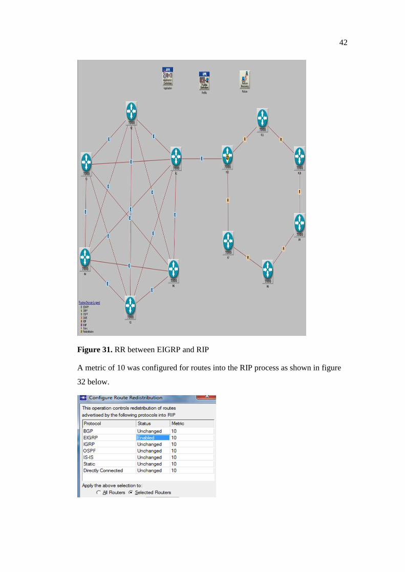
Figure 31. RR between EIGRP and RIP .............................................................. 42
Figure 32. RIP metric of RR ................................................................................ 43
Figure 33. Routing Table of RIP from R11. ........................................................ 43
Figure 34.. RR between EIGRP and OSPF using 6 ASBR .................................. 45
Figure 35. RR between EIGRP and IGRP ........................................................... 46
Figure 36. IGRP/EIGRP/OSPF for Multiple Point RR. ....................................... 47
Figure 37. IGRP/EIGRP/RIP Multiple Point RR. ................................................ 48
Figure 38. EIGRP/IGRP/RIP Multiple Point RR. ................................................ 49
Figure 39. Convergence Time for Single Point RR. ............................................ 50
Figure 40. Convergence Time for Multiple Point RR .......................................... 52
Figure 41. The graph of CT when EIGRP was replaced with IGRP ................... 53
Figure 42. ETE Delay for Single Point RR .......................................................... 55
Figure 43. ETE delay for Multiple Point RR ....................................................... 56
Figure 44. ETE Delay Variation for Single Point RR. ......................................... 57
Figure 45. ETE Delay Variation for Multiple Point RR. ..................................... 58
Figure 46. Queuing Delay for Single Point RR ................................................... 59
Figure 47. Queuing Delay for Multiple Point RR. ............................................... 60
LIST OF TABLES
Table 1. Default AD of Routing Protocols. /17/ ................................................... 21
Table 2. EIGRP/IGRP Composite metric. /18/ .................................................... 22
Table 3. OSPF1 and EIGRP Configuration. ......................................................... 23
Table 4. Performance Metrics for Single Point RR .............................................. 51
Table 5 Performance Metrics for Multiple Point RR ........................................... 51
Table 6. Rank Table ............................................................................................. 61
Table 7. Performance Analysis of Hybrid Networks for Single Point RR ........... 61
Table 8. Analysis of Hybrid Networks for Multiple Point RR ............................ 62
8
1 INTRODUCTION
In order to route data packets across networks, intelligent and dedicated devices
are needed. These devices (known as routers) make the decision to forward pack-
ets to its destination address by consulting a table called routing or forwarding ta-
ble. The router uses the routing table to look at a packet destination address and
determine the best route to take in transmitting the packets to its destination. Thus,
the routing table is populated by the router’ choice of the best path. /6/
Dynamic Routing protocols play an essential part in today’s communications net-
work; it is the internet heartbeat. /4/
All routing protocol performance differs from each other in terms of their conver-
gence quality, the end-to-end delay, jitter and throughput. Various routing proto-
cols exist in IP networks. /14/
In order for routes to be propagated between different routing domains; router
vendor has introduced a concept called route redistribution (RR). It is relatively
easy to manage a network configured with a single protocol. Multiple routing pro-
tocols within a network are quite complex and difficult to manage. There is there-
fore an increasing need to propagate route information across protocol boundaries
especially among networks configured with different routing protocols /13/
Consider a world class research industry working on a project in nanotechnology.
They intend to communicate with their research laboratory elsewhere in order to
exchange information. The two different sites are configured in Enhanced Interior
Gateway Routing Protocol (EIGRP) and Open Shortest Path First (OSPF).The
protocols can only communicate mutually if EIGRP routes are redistributing into
OSPF and vice versa. In this project work, one routing protocol will be injected
into another and route redistribution will be made.
9
2 BACKGROUND AND AIM OF THE PROJECT
An internetwork configured in different routing domains may intend to at least
temporarily share routing information among these instances. Thus, merger com-
panies whose networks are configured in say route information protocol OSPF
and EIGRP may in the course of merging decide exclusively to use EIGRP. The
process of migration from one routing protocol to another is time consuming and
may cause system failures. Thus, redistribution becomes a necessity for providing
temporal connectivity between two or more routing domains./3/
Mirzahossein Kiavash, Nguyen Michael and Elmasry Sarah (2013) in their design
work implemented Route Information Protocol (RIP), OSPF and EIGRP in the
simple ring and mesh topology. They also did work on a large mesh topology./12/
The configuration of route redistribution has also been done by many engineers
using software similar to a Cisco Packer Tracer program. The performance study
of these merged networks after configuring redistribution has been little studied.
The main idea in this thesis was to create a hybrid simple ring-mesh topology us-
ing border routers called Autonomous System Boundary Routers (ASBRs). These
routers are acting as intersects between these different routing domains. RR was
enabled on them, providing the possibility of bidirectional communication be-
tween the different routing processes. In so doing, it was possible to model an un-
realistically simple scenario of merging networks in order to study their perfor-
mance. Thus, by gradually progressing from simple topology to a more complex
hybrid ring–mesh, closely related models to real life communication networks
could be made. One or more (ASBRs) with RR was used to bridge these network
topologies.
In figure 1 below, EIGRP and OSPF were separately configured using the ASBR.
It is on this router that mutual RR can be performed. Thus, the routing table of the
ASBR will display EIGRP and OSPF routes.

10
Figure 1. Routing Domains of Routing Domains of EIGRP1 and OSPF1
This thesis will examine:
Which integrated network has the most reliable performance from an ex-
haustive analysis of all routing protocol performance characteristics such
as end-to-end delay, jitter, queuing delay and convergence time?
Which redistribution scenario has the fastest convergence time and small-
est end-to-end data delay, end-to-end delay variation and the least queuing
delay?
What hybrid is considered the most suitable in IP networks?
11
3 ROUTING PROTOCOLS AND ROUTE REDISTRIBUTION
Routing protocols (RP) are a set of processes and algorithms that give information
about remote networks and immediate adaptability whenever there exist a change
in network topology. They are broadly classified into link state or distance routing
protocol, classful or classless routing. A significant characteristic of routing pro-
tocols is how fast it converges when there is a change in topology. /1/
3.1 Link State Routing
Link state routing protocols perform a similar function to a road map. They are
newer and more complex routing protocols. They tracked the status and connec-
tion of each network and produced a calculated metric based on these factors. The
efficiency of the link state routing protocol is better when compared to that of the
distance vector routing protocol. It uses the Dijkstra algorithm to calculate the
path to the destination. OSPF is an example of link state routing. /16/
3.2 Distance Vector Routing Protocols
The distance vector routing protocol means that in this protocols routes are adver-
tised as vectors of distance and direction .In this protocol, the distance is ex-
pressed in terms of a matrix, such as hop count and direction is, therefore, the next
hop. RIPv1, IGRP and EIGRP are examples of distance vector routing proto-
cols./16/
3.3 Classful Routing and Classless Routing Protocols
Routing protocols, such as RIPv1, IGRP send routing update without subnet
masks and are thus are called classless protocol. The classful routing protocol uses
a variable subnet mask and sends a subnet mask along with their updates. EIGRP,
OSPF and RIPv2 are classless routing protocols. / 25/
12
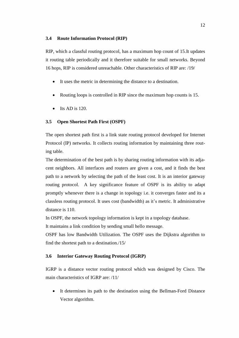
3.4 Route Information Protocol (RIP)
RIP, which a classful routing protocol, has a maximum hop count of 15.It updates
it routing table periodically and it therefore suitable for small networks. Beyond
16 hops, RIP is considered unreachable. Other characteristics of RIP are: /19/
It uses the metric in determining the distance to a destination.
Routing loops is controlled in RIP since the maximum hop counts is 15.
Its AD is 120.
3.5 Open Shortest Path First (OSPF)
The open shortest path first is a link state routing protocol developed for Internet
Protocol (IP) networks. It collects routing information by maintaining three rout-
ing table.
The determination of the best path is by sharing routing information with its adja-
cent neighbors. All interfaces and routers are given a cost, and it finds the best
path to a network by selecting the path of the least cost. It is an interior gateway
routing protocol. A key significance feature of OSPF is its ability to adapt
promptly whenever there is a change in topology i.e. it converges faster and its a
classless routing protocol. It uses cost (bandwidth) as it’s metric. It administrative
distance is 110.
In OSPF, the network topology information is kept in a topology database.
It maintains a link condition by sending small hello message.
OSPF has low Bandwidth Utilization. The OSPF uses the Dijkstra algorithm to
find the shortest path to a destination./15/
3.6 Interior Gateway Routing Protocol (IGRP)
IGRP is a distance vector routing protocol which was designed by Cisco. The
main characteristics of IGRP are: /11/
It determines its path to the destination using the Bellman-Ford Distance
Vector algorithm.
13
Its AD is 100.
The maximum number of hops count supported by default is 100.
IP routing is supported by IGRP.
It sends subnet masks along with its updates and thus it is classless.
It has a fast convergence and uses it composite metric of bandwidth, delay, MTU,
reliability, load as its metric.
3.7 Enhanced Interior Gateway Routing Protocol (EIGRP)
The Enhanced interior gateway routing protocol (EIGRP) is a hybrid routing pro-
tocol developed by Cisco. Its features and capabilities are far more than that of the
family from which it came. It is an advanced distance vector routing protocol and
uses bandwidth and delay as a metric. It was developed to replace IGRP. It was
solely designed to have a class such that is will be possible for the protocol to in-
clude variable length subnet masks and classless. It has high convergence quality
as it utilizes the Diffused Update Algorithm in calculating the shortest path to the
destination. EIGRP characteristics are given below.
• EIGRP convergence quality is very high and can store its neighbor route in
a neighbor table and topology table respectively.
• Compared to RIP and OSPF, which send periodic and full updates, EIGRP
send partial trigger updates when a change occurs. These updates contain only in-
formation of the route that has changed. The characteristics of EIGRP listed be-
low.
• It is a classless routing protocol.
• It uses the Diffusing Update Algorithm (DUAL) to determine its best path
when forwarding a data packet to its final destination.
• Its administrative distance of 90 is applied for internal routes
• EIGRP uses an administrative distance of 170 for route marks as exter-
nal./8/
14
3.8 Network Performance Metrics
The performance metrics of routing protocols includes the average queuing delay,
the end-to-end delay, the end-to-end delay variation (jitter) and convergence time.
3.8.1 Average Queuing Delay
The queuing delay implies the time taken from the packets arrival at the queue to
the time it leave and gets transmitted. In real–time video applications, the smaller
the queuing delay, the better. /5/
3.8.2 End-to-End Delay of Data Packets
The end-to-end delay is the average of all delays encountered by the data packet
as it travels from the source to the destination. The smaller the end-to-end delay,
the better the networks./5/
3.8.3 End-to-End Delay Variation.
As packets transit from the source to the destination, they encounter different kind
of delays. The variance in this delay is the end-to-end delay variation. The posi-
tion of data in the different queue and its size affects the jitter. A small amount of
jitter implies good transmission quality./5/
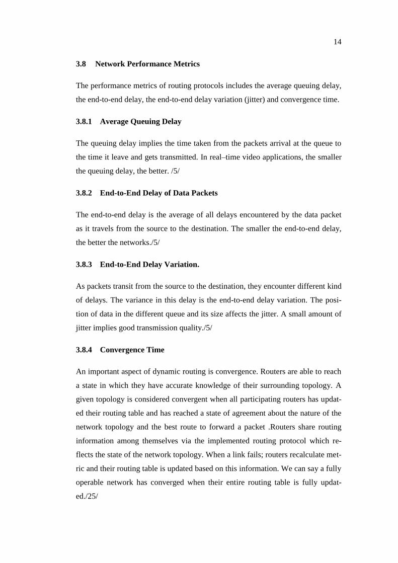
3.8.4 Convergence Time
An important aspect of dynamic routing is convergence. Routers are able to reach
a state in which they have accurate knowledge of their surrounding topology. A
given topology is considered convergent when all participating routers has updat-
ed their routing table and has reached a state of agreement about the nature of the
network topology and the best route to forward a packet .Routers share routing
information among themselves via the implemented routing protocol which re-
flects the state of the network topology. When a link fails; routers recalculate met-
ric and their routing table is updated based on this information. We can say a fully
operable network has converged when their entire routing table is fully updat-
ed./25/
15
Figure 2. Convergence of Routing Protocols./2/
3.9 Network Topology
The structural arrangement pattern of all interconnected devices in a network re-
fers to a network topology. Types of topology are trees, ring, mesh and star. The
ring and mesh topology and discussed below.
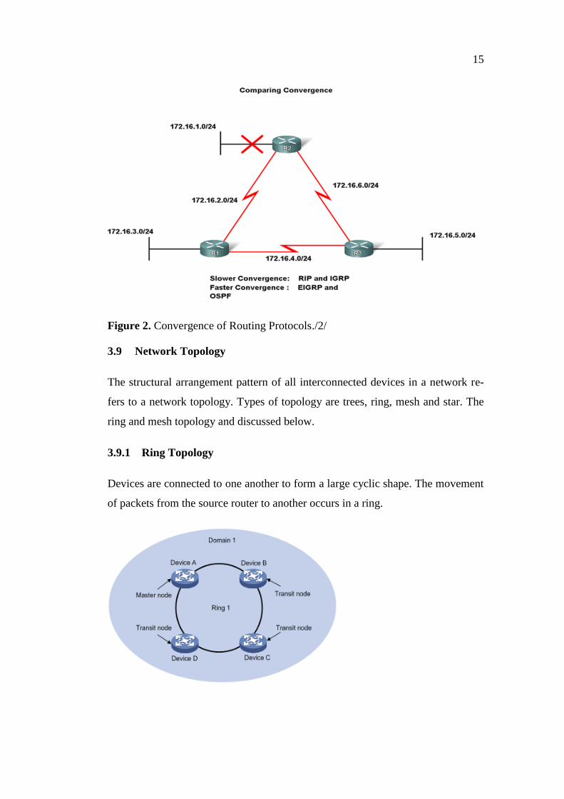
3.9.1 Ring Topology
Devices are connected to one another to form a large cyclic shape. The movement
of packets from the source router to another occurs in a ring.
16
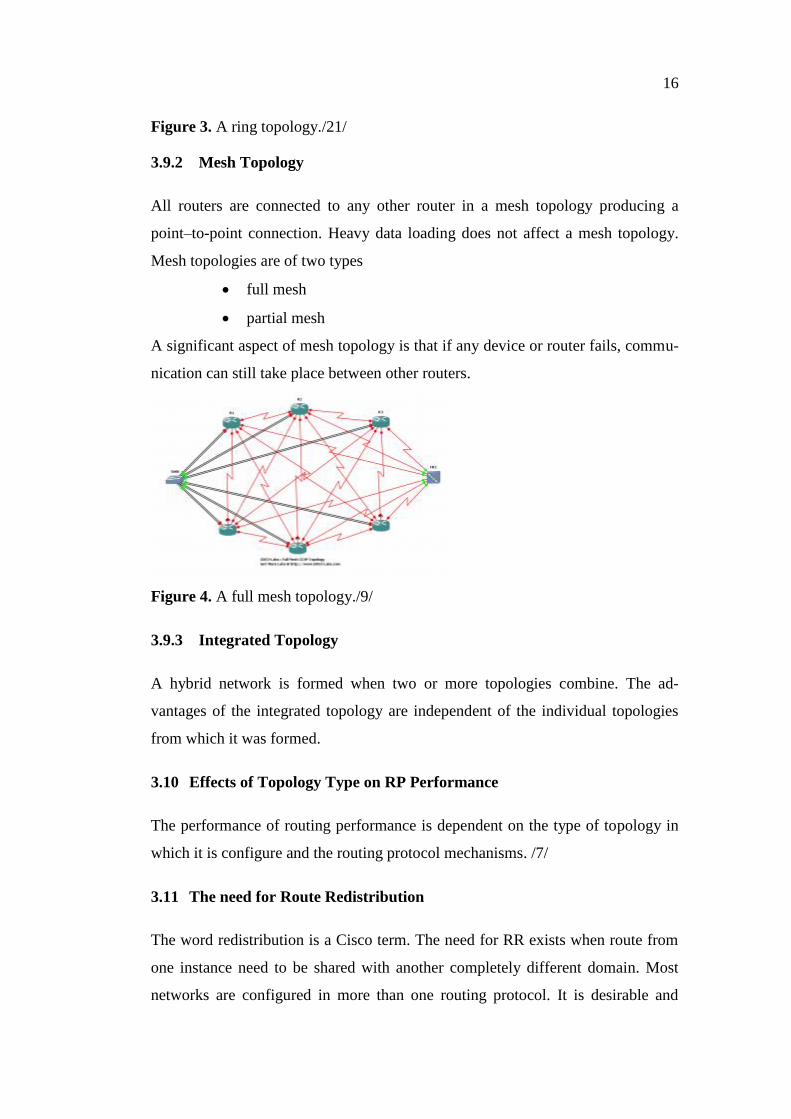
Figure 3. A ring topology./21/
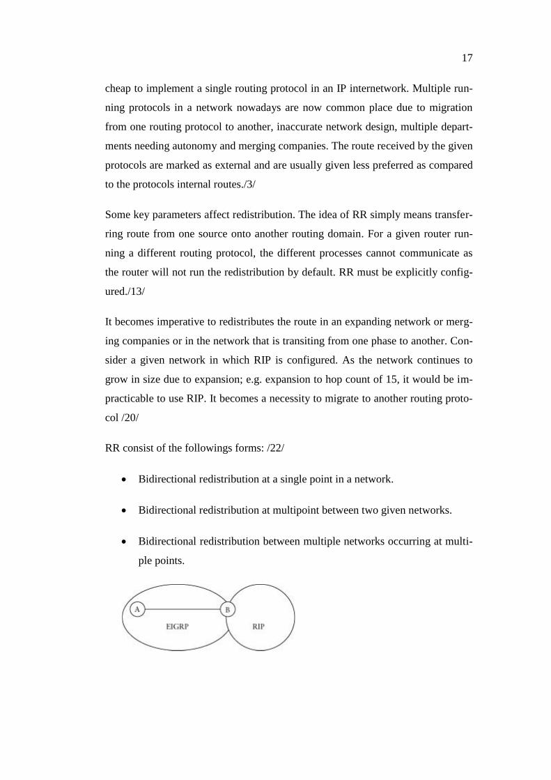
3.9.2 Mesh Topology
All routers are connected to any other router in a mesh topology producing a
point–to-point connection. Heavy data loading does not affect a mesh topology.
Mesh topologies are of two types
full mesh
partial mesh
A significant aspect of mesh topology is that if any device or router fails, commu-
nication can still take place between other routers.
Figure 4. A full mesh topology./9/
3.9.3 Integrated Topology
A hybrid network is formed when two or more topologies combine. The ad-
vantages of the integrated topology are independent of the individual topologies
from which it was formed.
3.10 Effects of Topology Type on RP Performance
The performance of routing performance is dependent on the type of topology in
which it is configure and the routing protocol mechanisms. /7/
3.11 The need for Route Redistribution
The word redistribution is a Cisco term. The need for RR exists when route from
one instance need to be shared with another completely different domain. Most
networks are configured in more than one routing protocol. It is desirable and
17
cheap to implement a single routing protocol in an IP internetwork. Multiple run-
ning protocols in a network nowadays are now common place due to migration
from one routing protocol to another, inaccurate network design, multiple depart-
ments needing autonomy and merging companies. The route received by the given
protocols are marked as external and are usually given less preferred as compared
to the protocols internal routes./3/
Some key parameters affect redistribution. The idea of RR simply means transfer-
ring route from one source onto another routing domain. For a given router run-
ning a different routing protocol, the different processes cannot communicate as
the router will not run the redistribution by default. RR must be explicitly config-
ured./13/
It becomes imperative to redistributes the route in an expanding network or merg-
ing companies or in the network that is transiting from one phase to another. Con-
sider a given network in which RIP is configured. As the network continues to
grow in size due to expansion; e.g. expansion to hop count of 15, it would be im-
practicable to use RIP. It becomes a necessity to migrate to another routing proto-
col /20/
RR consist of the followings forms: /22/
Bidirectional redistribution at a single point in a network.
Bidirectional redistribution at multipoint between two given networks.
Bidirectional redistribution between multiple networks occurring at multi-
ple points.
18
Figure 5. Single Point Mutual RR /22/
One-way redistribution involves the injected of routes from one routing protocol
to another and occurs in one direction only and bidirectional (mutual) redistribu-
tion occurs in both direction which may involves one or multiple points in a net-
works./22/
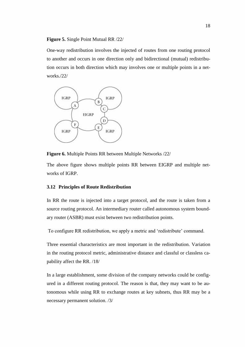
Figure 6. Multiple Points RR between Multiple Networks /22/
The above figure shows multiple points RR between EIGRP and multiple net-
works of IGRP.
3.12 Principles of Route Redistribution
In RR the route is injected into a target protocol, and the route is taken from a
source routing protocol. An intermediary router called autonomous system bound-
ary router (ASBR) must exist between two redistribution points.
To configure RR redistribution, we apply a metric and ‘redistribute’ command.
Three essential characteristics are most important in the redistribution. Variation
in the routing protocol metric, administrative distance and classful or classless ca-
pability affect the RR. /18/
In a large establishment, some division of the company networks could be config-
ured in a different routing protocol. The reason is that, they may want to be au-
tonomous while using RR to exchange routes at key subnets, thus RR may be a
necessary permanent solution. /3/
19
3.13 Metric
The metric is a very significant factor is redistribution. In redistributing the routes
across the routers, the metric of one routing protocol differing from the other. The
RIP Information protocol uses hop count as its metric. EIGRP uses a combination
of MTU, delay reliability. OSPF uses cost as its metric, while EIGRP uses a com-
bination of bandwidth and delay. An understandable must be configured when
redistributing routes between different processes.
When a given protocol say RIP is redistributed into EIGRP. RIP uses cost and
EGRP uses a composite of bandwidth and delay. The metric of RIP is disregard-
ed. It is only EIGRP metric that will be used. /18/
3.14 Administrative Distance
The administrative distance measures the reliability of a given routing protocol.
The lesser the administrative distance, the more reliable the network. It is an inte-
ger value with a range of 0 to 255.
When two routing protocols are implemented in networks, the administrative dis-
tance becomes a key factor in determining the best route to a destination.
A redistributed route, nevertheless will inherit the administrative distance of the
redistributed protocol. /18/
The figure 7 below show the EIGRP uses an AD 90 for routes within its domain
while RIP uses an AD of 120.Thus, the two protocols cannot communicate .When
redistributing RIP routes into EIGRP; an AD acceptable to the two routing proto-
cols is used.
20
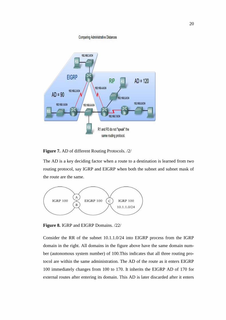
Figure 7. AD of different Routing Protocols. /2/
The AD is a key deciding factor when a route to a destination is learned from two
routing protocol, say IGRP and EIGRP when both the subnet and subnet mask of
the route are the same.
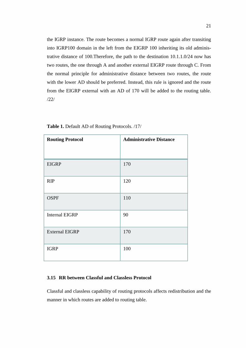
Figure 8. IGRP and EIGRP Domains. /22/
Consider the RR of the subnet 10.1.1.0/24 into EIGRP process from the IGRP
domain in the right. All domains in the figure above have the same domain num-
ber (autonomous system number) of 100.This indicates that all three routing pro-
tocol are within the same administration. The AD of the route as it enters EIGRP
100 immediately changes from 100 to 170. It inherits the EIGRP AD of 170 for
external routes after entering its domain. This AD is later discarded after it enters
21
the IGRP instance. The route becomes a normal IGRP route again after transiting
into IGRP100 domain in the left from the EIGRP 100 inheriting its old adminis-
trative distance of 100.Therefore, the path to the destination 10.1.1.0/24 now has
two routes, the one through A and another external EIGRP route through C. From
the normal principle for administrative distance between two routes, the route
with the lower AD should be preferred. Instead, this rule is ignored and the route
from the EIGRP external with an AD of 170 will be added to the routing table.
/22/
Table 1. Default AD of Routing Protocols. /17/
Routing Protocol Administrative Distance
EIGRP 170
RIP 120
OSPF 110
Internal EIGRP 90
External EIGRP 170
IGRP 100
3.15 RR between Classful and Classless Protocol
Classful and classless capability of routing protocols affects redistribution and the
manner in which routes are added to routing table.

22
3.15.1 Redistributing into RIP
The RIP uses hop count as its metric. The maximum metric is 15.A metric of 10
was defined in OPNET Modeler for routes redistributing into RIP. /18/
3.15.2 Redistributing into OSPF
. For routes injected into OSPF, the following applies: /18/
The metric or cost of the source route is used if redistributing from another
OSPF instances
Route learned from the Border gateway protocol uses a cost of 1
A cost of 20 is used for all other routes.
3.15.3 Redistributing Routes into EIGRP/IGRP
EIGRP uses the bandwidth and delay in calculating its distance metric. In redis-
tributing routes into EIGRP/IGRP, it is still important to specify all five compo-
site metric. The standard metric values are tabulated below. /18/
Table 2. EIGRP/IGRP Composite metric. /18/
Distance Metric Value
Bandwidth 10000
Reliability 255
Load 1
MTU 1500
Delay 1000
23
If no metric if specified, EIGRP/IGRP will use a default metric of 0 and no route
will be redistributed.
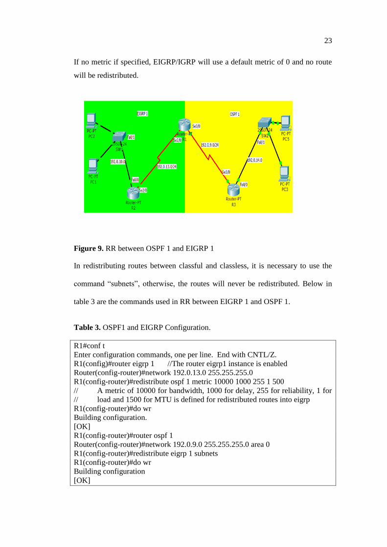
Figure 9. RR between OSPF 1 and EIGRP 1
In redistributing routes between classful and classless, it is necessary to use the
command “subnets”, otherwise, the routes will never be redistributed. Below in
table 3 are the commands used in RR between EIGRP 1 and OSPF 1.
Table 3. OSPF1 and EIGRP Configuration.
R1#conf t
Enter configuration commands, one per line. End with CNTL/Z.
R1(config)#router eigrp 1 //The router eigrp1 instance is enabled
Router(config-router)#network 192.0.13.0 255.255.255.0
R1(config-router)#redistribute ospf 1 metric 10000 1000 255 1 500
// A metric of 10000 for bandwidth, 1000 for delay, 255 for reliability, 1 for
// load and 1500 for MTU is defined for redistributed routes into eigrp
R1(config-router)#do wr
Building configuration.
[OK]
R1(config-router)#router ospf 1
Router(config-router)#network 192.0.9.0 255.255.255.0 area 0
R1(config-router)#redistribute eigrp 1 subnets
R1(config-router)#do wr
Building configuration
[OK]
24
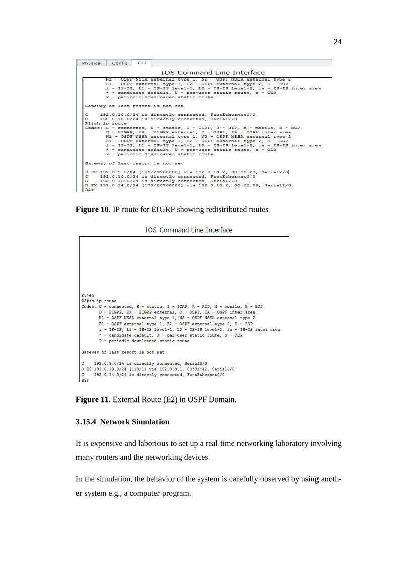
Figure 10. IP route for EIGRP showing redistributed routes
Figure 11. External Route (E2) in OSPF Domain.
3.15.4 Network Simulation
It is expensive and laborious to set up a real-time networking laboratory involving
many routers and the networking devices.
In the simulation, the behavior of the system is carefully observed by using anoth-
er system e.g., a computer program.
25
The computer-assisted simulation is an important aspect of modern design. Real-
time behavior a system can be hypothetically modelled and its performance is
then critically observed to know how it will behave under different conditions.
Simulation is an imperative modern technology. It has application in science, en-
gineering, or other applications fields for different purposes.
Industries and universities research center are widely using software simulation
nowadays. It is relatively cheap and saves time to pretest proposed protocols and
wireless networks./23/
3.15.5 Introduction to OPNET Simulation
The Optimized Network Engineering Tools, OPNET is the industry's leading net-
work development software introduced in 1986 by a student of MIT. /10/
It has immense application among engineers, university students, researchers and
the US military./26/
OPNET performs the following functions:
•simulation of telecommunication and network environment
•It performs simulation of a given system behavior by modelling each
event in the system through user defined processes. /14/
•In network simulation, real-time traffic such as voice calling, video con-
ferencing, and emails are used.
3.15.6 OPNET Modeler Component Description
The application configuration, profile configuration and failure recovery are the
components used in this project
26
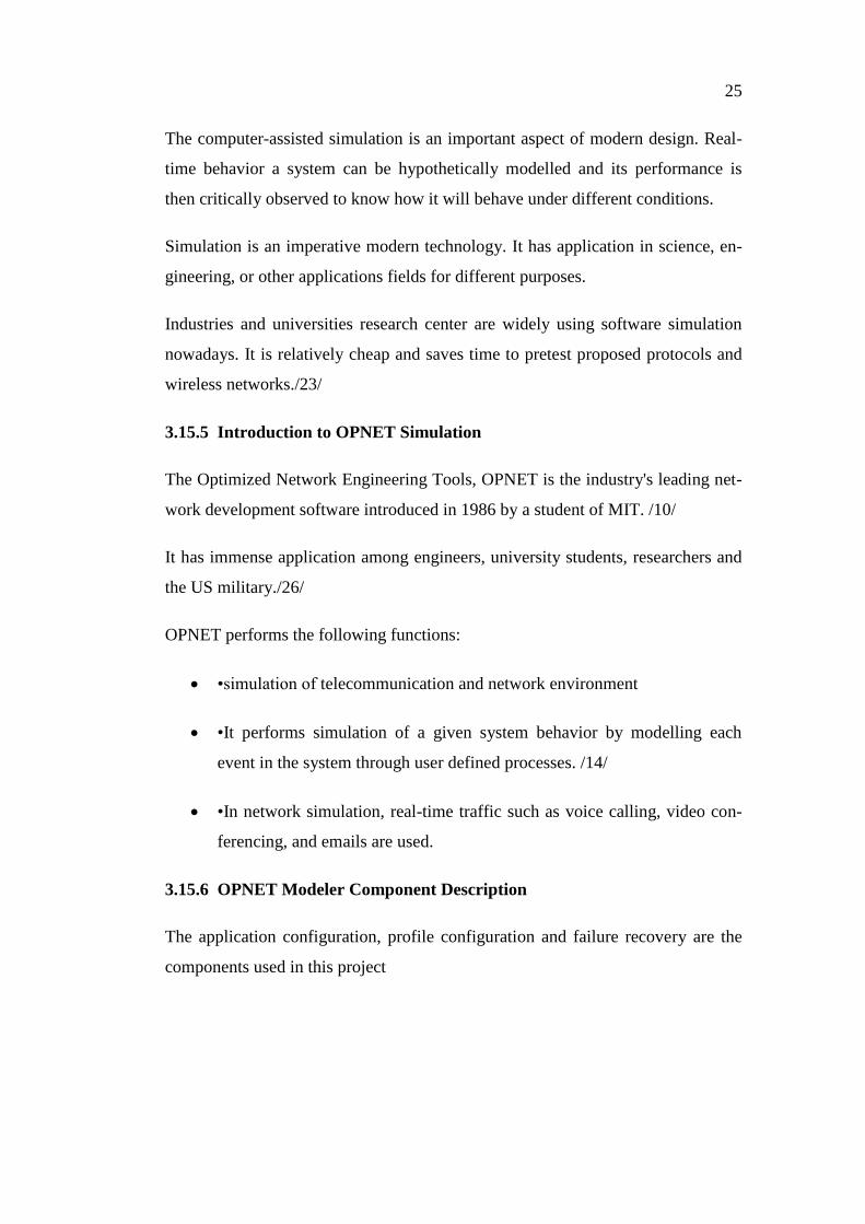
Figure 12. Application Definition, Profile Definition and Failure Recovery
The application definition object performs the function of generating different
types of traffic. It can generate video streaming (light) and video conferencing
traffic in real time. The injection of real-time traffic is done by the profile and ap-
plication object /24/
The Failure Recovery is used in configuring a given router to failure and recover
at different times./24/
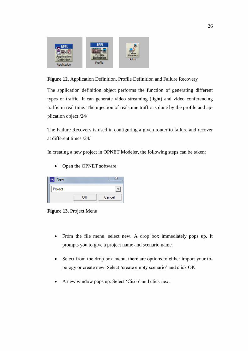
In creating a new project in OPNET Modeler, the following steps can be taken:
Open the OPNET software
Figure 13. Project Menu
From the file menu, select new. A drop box immediately pops up. It
prompts you to give a project name and scenario name.
Select from the drop box menu, there are options to either import your to-
pology or create new. Select ‘create empty scenario’ and click OK.
A new window pops up. Select ‘Cisco’ and click next
27
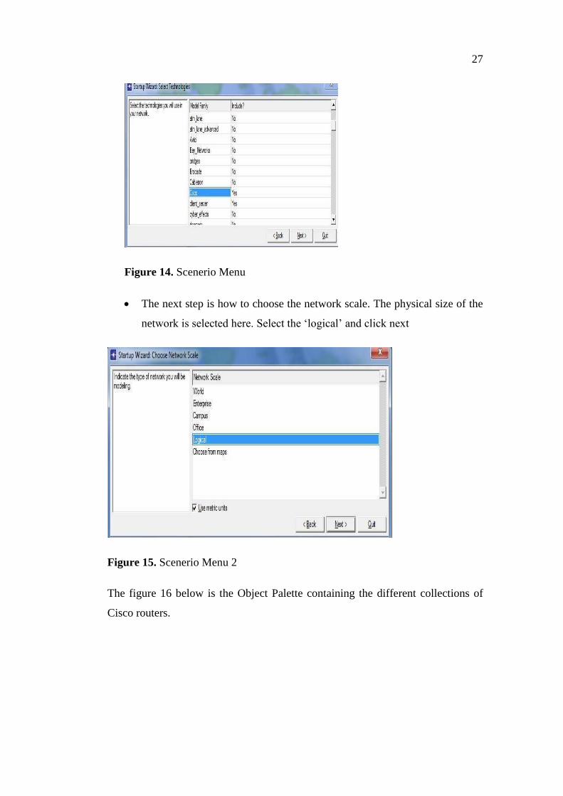
Figure 14. Scenerio Menu
The next step is how to choose the network scale. The physical size of the
network is selected here. Select the ‘logical’ and click next
Figure 15. Scenerio Menu 2
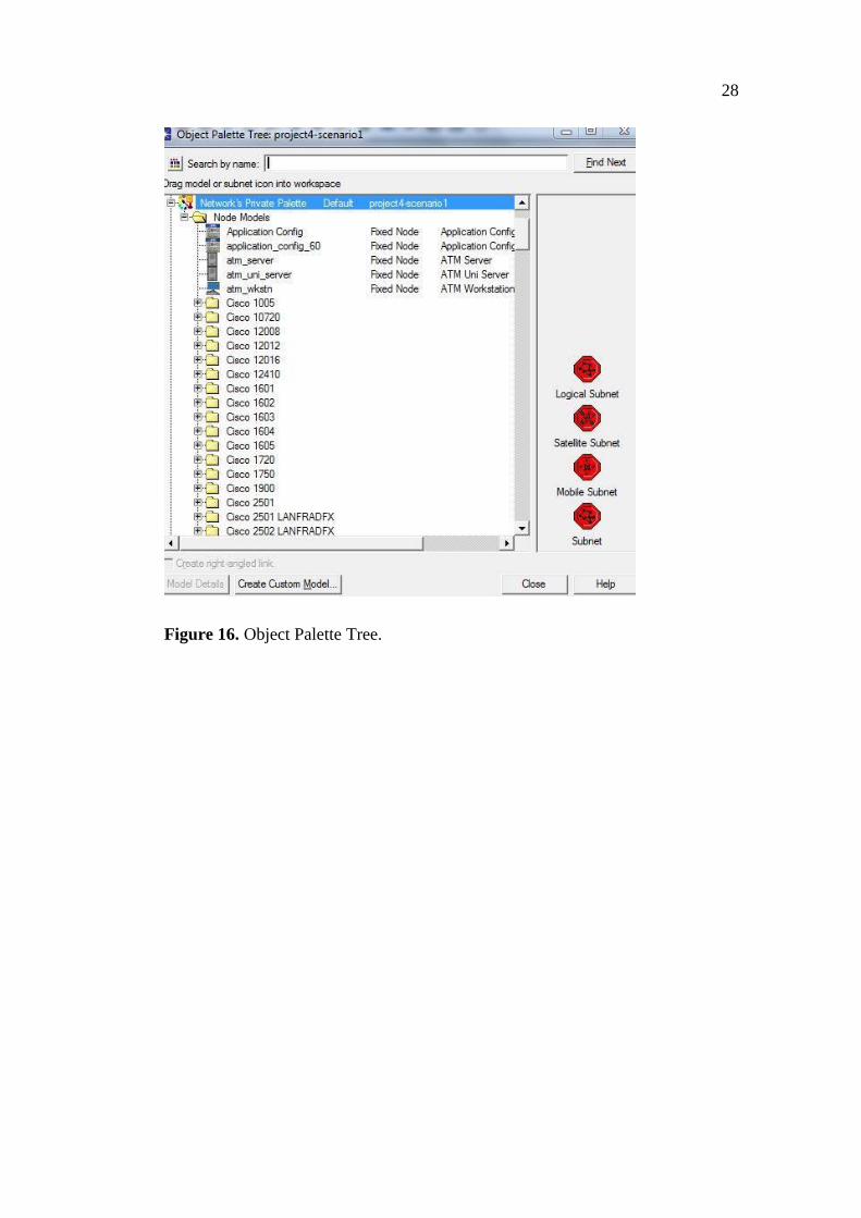
The figure 16 below is the Object Palette containing the different collections of
Cisco routers.
28
Figure 16. Object Palette Tree.
29
4 DESIGN AND IMPLEMENTATION OF RR
The design was made for a mutual redistribution of either of RIP, OSPF or IGRP
into EIGRP considering first a simple network topology. The complexity of the
topology was thereafter increased. In this design it was assumed that all other
(OSPF, RIP AND IGRP) domains intend to exchange their routes with EIGRP. It
is used as a mesh since mesh is expensive; hence less of it is used. All other rout-
ing protocols were configured in a ring topology as ring is economically more ef-
fective. Hybrid mesh-ring is form.
The first of this task was to create two autonomous systems with EIGRP config-
ured in mesh and OSPF, RIP or IGRP implemented in a ring topology. RR redis-
tribution was done at the border router to enable bidirectional communication be-
tween the two instances. Simple and complex redistribution scenarios were creat-
ed.
The first scenario involves 6 Cisco routers, a configuration application, profile
and link failure, Cisco 7000 routers, PPP_DS DUPLIX LINK.
The OPNET Modeler rapid configuration tool was used to create a mesh and ring
topology of 6 routers each for both routing protocols. A single router, called an
autonomous system boundary router was used to redistributes the routes mutually
between the two routing protocols.
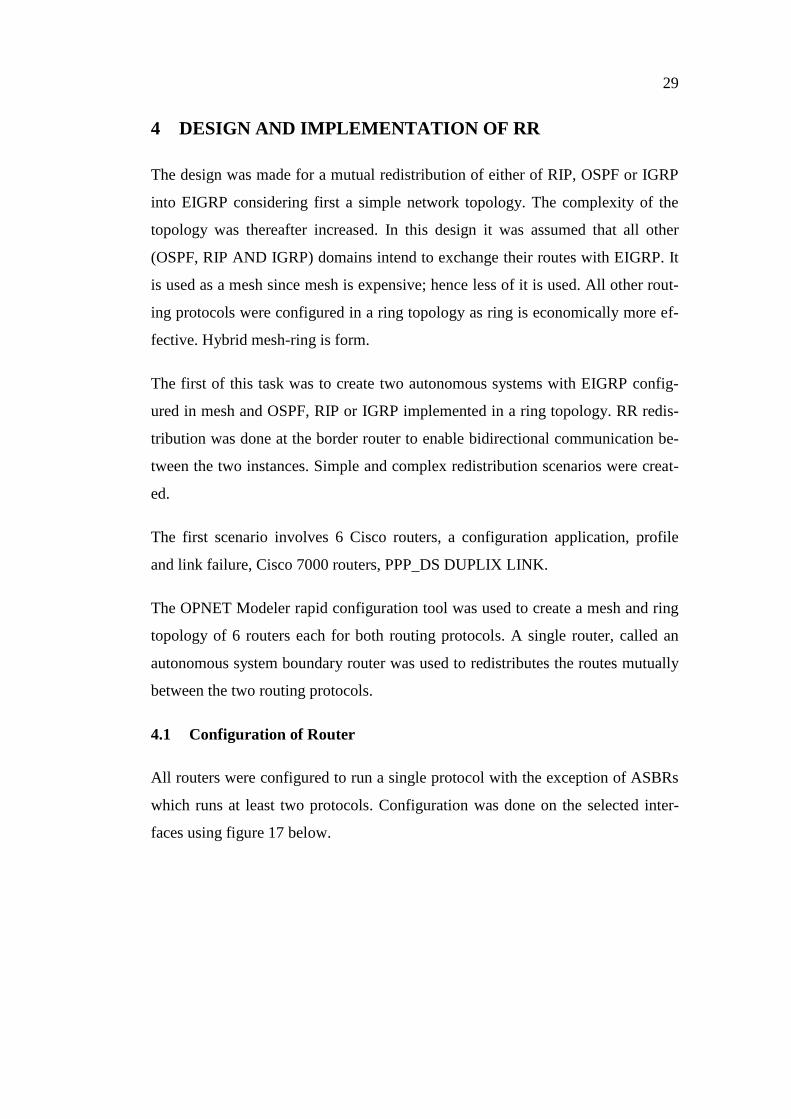
4.1 Configuration of Router
All routers were configured to run a single protocol with the exception of ASBRs
which runs at least two protocols. Configuration was done on the selected inter-
faces using figure 17 below.
30
Figure 17. Routing Protocol Configuration
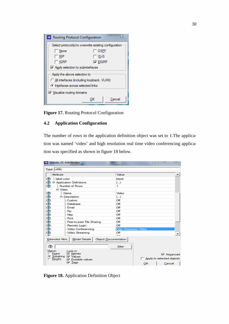
4.2 Application Configuration
The number of rows in the application definition object was set to 1.The applica-
tion was named ‘video’ and high resolution real time video conferencing applica-
tion was specified as shown in figure 18 below.
Figure 18. Application Definition Object
31
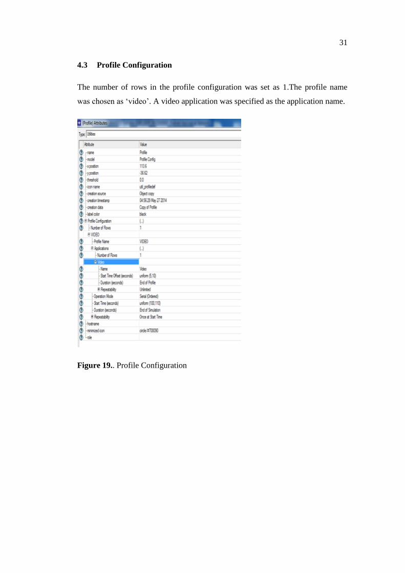
4.3 Profile Configuration
The number of rows in the profile configuration was set as 1.The profile name
was chosen as ‘video’. A video application was specified as the application name.
Figure 19.. Profile Configuration
32
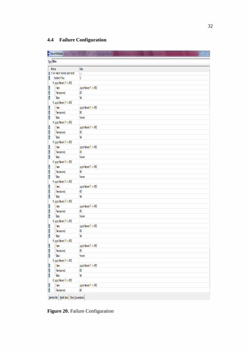
4.4 Failure Configuration
Figure 20. Failure Configuration
33
The R1 and R12 was configured to failure and recover at different times. Any dis-
turbance in the topology creates an additional time for the network to converge.
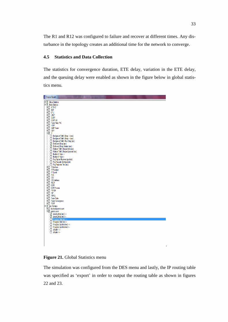
4.5 Statistics and Data Collection
The statistics for convergence duration, ETE delay, variation in the ETE delay,
and the queuing delay were enabled as shown in the figure below in global statis-
tics menu.
.
Figure 21. Global Statistics menu
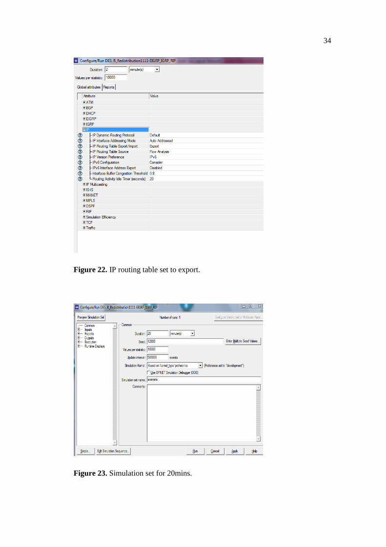
The simulation was configured from the DES menu and lastly, the IP routing table
was specified as ‘export’ in order to output the routing table as shown in figures
22 and 23.
34
Figure 22. IP routing table set to export.
Figure 23. Simulation set for 20mins.
35
The description of implementation here was subdivided into the following parts.
4.6 Single Point (SP) RR
RR between EIGRP and OSPF
RR between EIGRP and IGRIP
RR between EIGRP and RIP
4.7 Multiple Point (MP) RR
The second part of the project consist of three scenarios
Injecting OSPF into EIGRP(and vice versa)
RR between EIGRP and IGRP
RR between EIGRP and RIP
4.8 Multiple Point RR between Three Routing Protocols
The third part consist of three routing protocols made up of three scenarios: The
design is similar to the second, instead of using six domains of OSPF or IGRP in a
topology, three domains of each were used, while keeping EIGRP in mesh un-
changed. Thus, 3 ASBRs were used to perform RR between EIGRP and OSPF,
and 3 ASBRs to also redistribute routes between EIGRP and IGRP. The scenarios
to be considered includes:
IGRP/EIGRP/OSPF
IGRP/EIGRP/RIP
EIGRP/IGRP/RIP.
The design for SP RR was made in a such way that EIGRP was implemented in a
mesh topology consisting of six routers and one other routing domain (in a ring
topology) was merged with it using a single ASBR.EIGRP was configured in a
36
mesh since the topology can withstand huge traffic, providing room for future
complexity of the networks as more instances of another routing protocol may be
added to it. Since it is the most important domains in which all other lesser de-
partments has to exchange data, the mesh topology is necessary. The failure of
one of the links will not affect the entire EIGRP instance. The merging was neces-
sary considering simple networks configured in either of RIP, OSPF and IGRP.
These domains may want to be autonomous and intend to manage their networks,
while exchanging routes at key subnets.
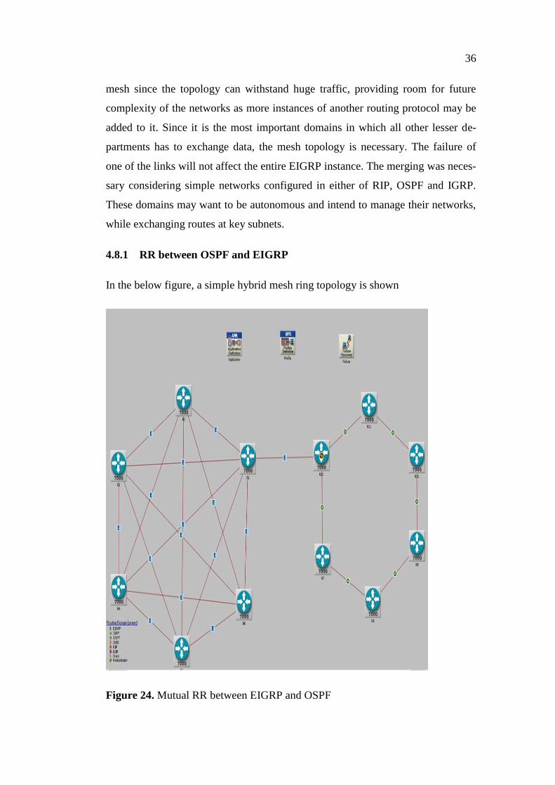
4.8.1 RR between OSPF and EIGRP
In the below figure, a simple hybrid mesh ring topology is shown
Figure 24. Mutual RR between EIGRP and OSPF
37
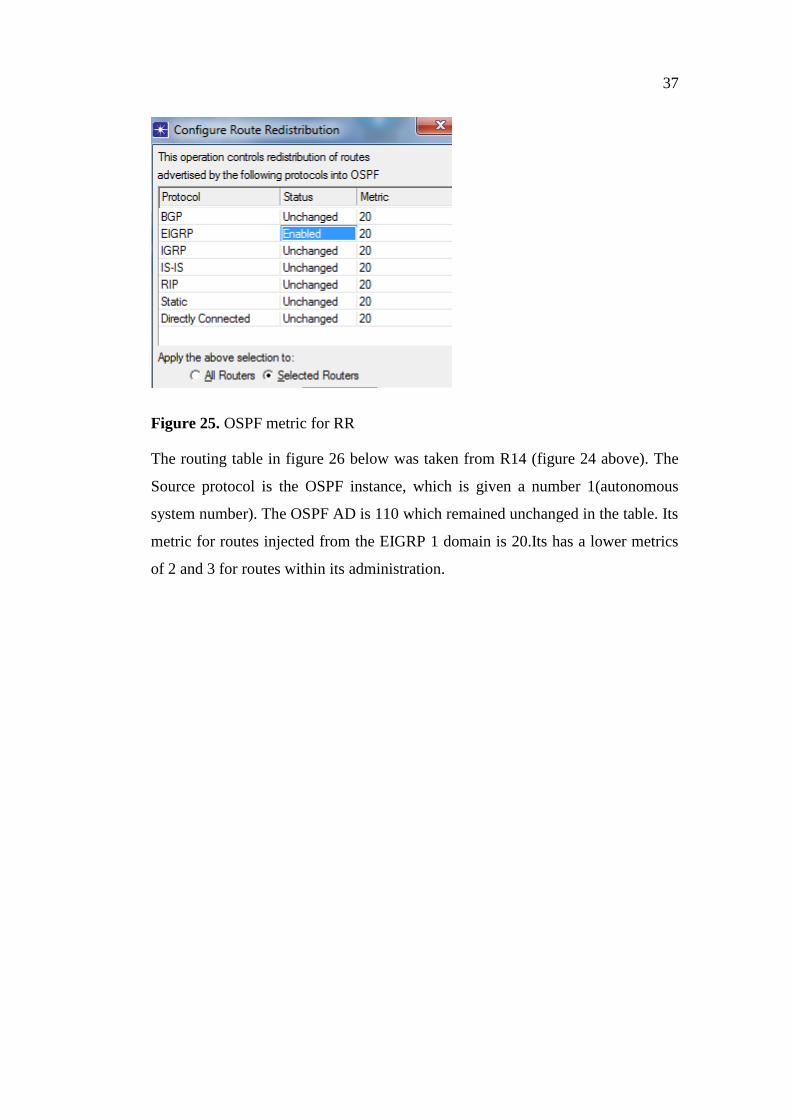
Figure 25. OSPF metric for RR
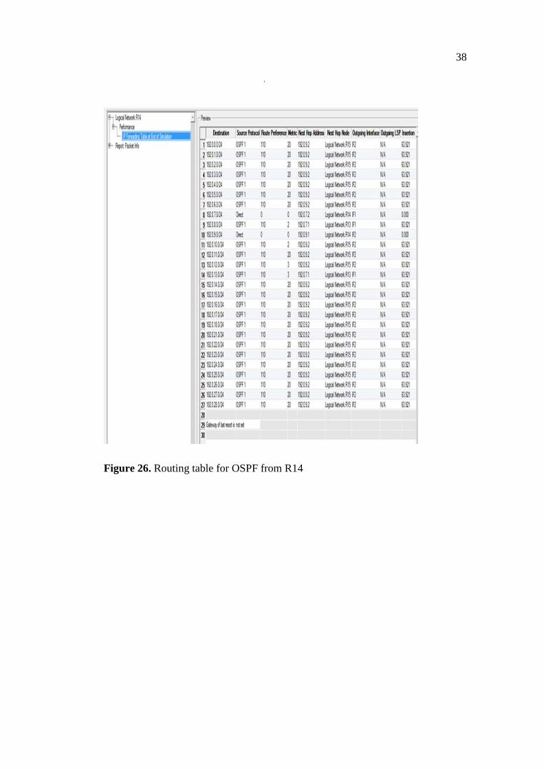
The routing table in figure 26 below was taken from R14 (figure 24 above). The
Source protocol is the OSPF instance, which is given a number 1(autonomous
system number). The OSPF AD is 110 which remained unchanged in the table. Its
metric for routes injected from the EIGRP 1 domain is 20.Its has a lower metrics
of 2 and 3 for routes within its administration.
38
Figure 26. Routing table for OSPF from R14
39
26
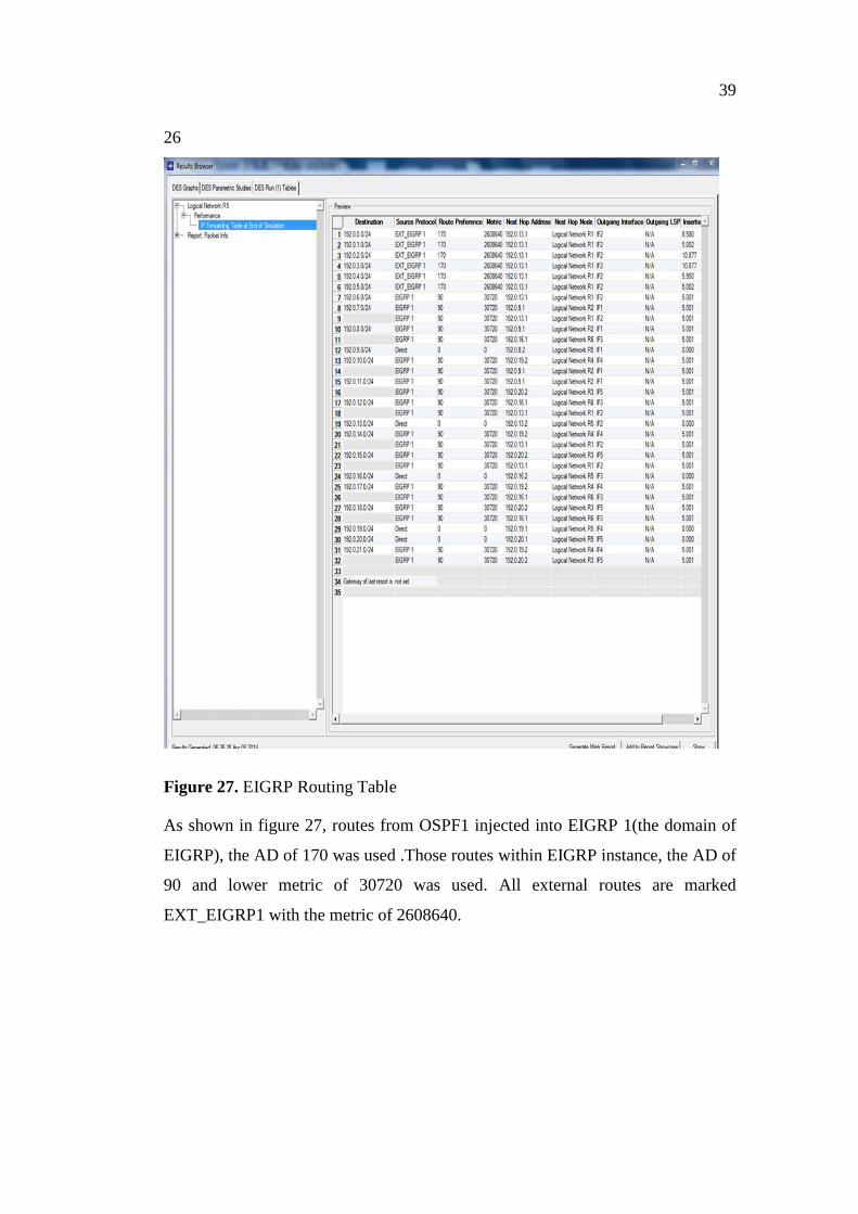
Figure 27. EIGRP Routing Table
As shown in figure 27, routes from OSPF1 injected into EIGRP 1(the domain of
EIGRP), the AD of 170 was used .Those routes within EIGRP instance, the AD of
90 and lower metric of 30720 was used. All external routes are marked
EXT_EIGRP1 with the metric of 2608640.

40
Figure 28. EIGRP/OSPF Hybrid Topology for Single Point RR
OSPF in figure 24 above was replaced with IGRP. Below is a screenshot from
OPNET modeler of composite metrics used by EIGRP/IGRP in the redistribution
of routes.
41
Figure 29. IGRP RR Metrics
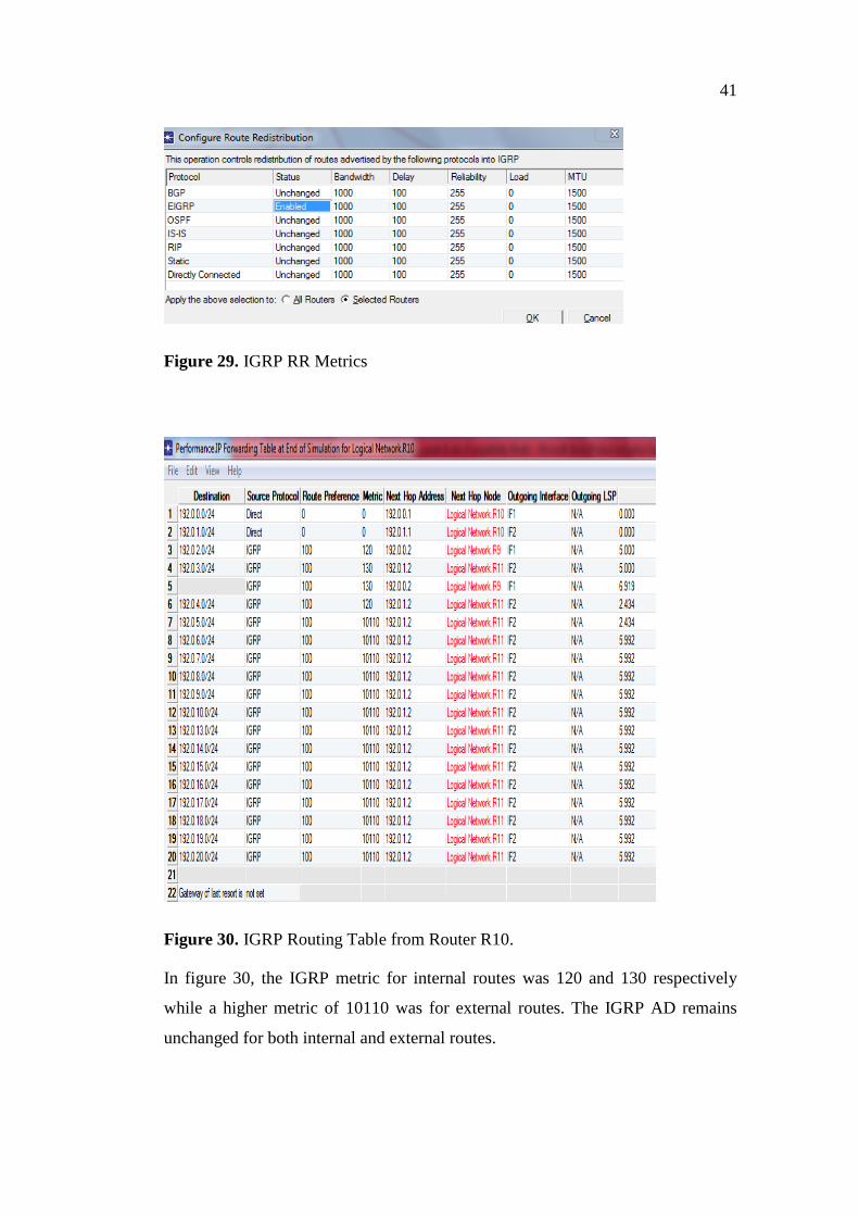
Figure 30. IGRP Routing Table from Router R10.
In figure 30, the IGRP metric for internal routes was 120 and 130 respectively
while a higher metric of 10110 was for external routes. The IGRP AD remains
unchanged for both internal and external routes.
42
Figure 31. RR between EIGRP and RIP
A metric of 10 was configured for routes into the RIP process as shown in figure
32 below.

43
Figure 32. RIP metric of RR
As shown in figure 33 below, the lower metrics of 1 and 2 was used for routes in-
ternal to RIP and the higher metrics of 11 was used for external routes
Figure 33. Routing Table of RIP from R11.
4.9 Multiple Point Redistribution
In this part, six ASBR were used in performing the route redistribution. EIGRP
was implemented in a mesh topology consisting of six routers. It is assumed here
that all others domains intend to exchange routes with EIGRP. In real situation, a
given research center, with the decision to configure its entire network to be using
only EIGRP, built and configured a new main center in mesh topology. It intend-
ed temporarily to exchange information with other lesser departments previously
using RIP, IGRP and OSPF before migration to exclusive EIGRP use is fully
completed.
44
RR between EIGRP and multiple networks of OSPF
RR between EIGRP and multiple networks of IGRP
RR between EIGRP and multiple networks of RIP
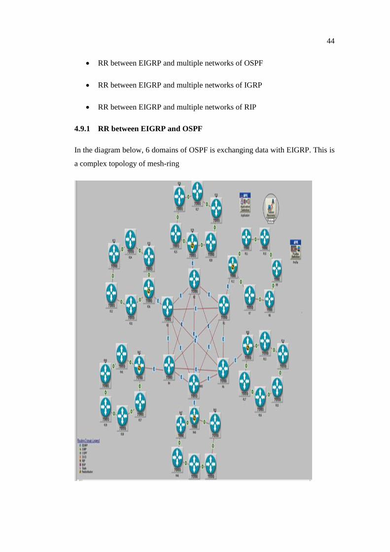
4.9.1 RR between EIGRP and OSPF
In the diagram below, 6 domains of OSPF is exchanging data with EIGRP. This is
a complex topology of mesh-ring
45
Figure 34.. RR between EIGRP and OSPF using 6 ASBR
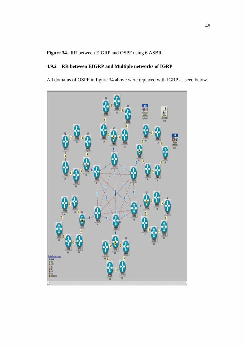
4.9.2 RR between EIGRP and Multiple networks of IGRP
All domains of OSPF in figure 34 above were replaced with IGRP as seen below.
46
Figure 35. RR between EIGRP and IGRP
4.10 Mutual Redistribution between Three Routing Domains
RR between OSPF, EIGRP and RIP using 3 ASBR for redistributing
routes between OSPF and EIGRP and 3 ASBR for redistributing routes
between EIGRP and RIP.
RR between OSPF, EIGRP and RIP, using 3 ASBR each.
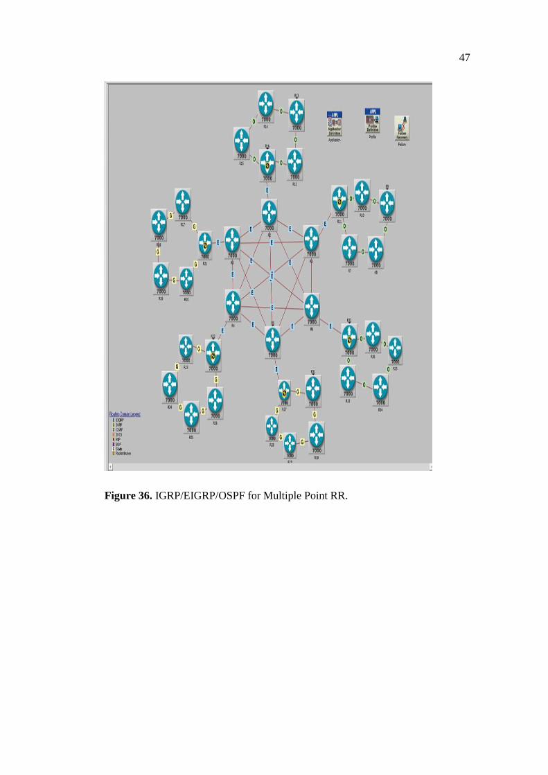
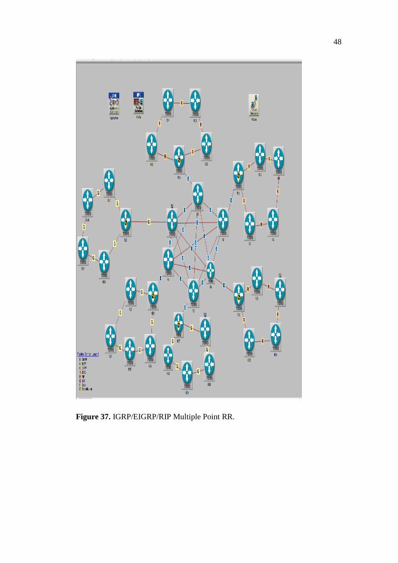
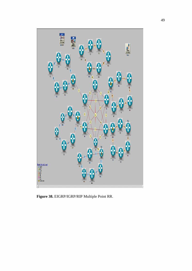
The designs in figure 36, 37 and 38 were done in such a way that one ASBR is
redistributing routes between IGRP and EIGRP and another ASBR is also redis-
tributing routes between EIGRP and OSPF. It is analogous to the system made up
of seven divisions of a company having three of its divisions using IGRP and an-
other three configured in OSPF. All six divisions may decide exclusively to man-
age their own networks, but must exchange route at key subnets with a main cen-
ter using mesh topology. In the design, more of a ring, which is cheap is used and
less of mesh-an expensive topology is used, making the hybrid network economi-
cally effective.
47
Figure 36. IGRP/EIGRP/OSPF for Multiple Point RR.
48
Figure 37. IGRP/EIGRP/RIP Multiple Point RR.
49
Figure 38. EIGRP/IGRP/RIP Multiple Point RR.
50
5 RESULTS AND ANALYSIS
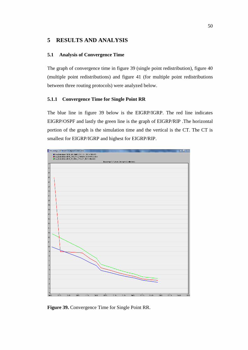
5.1 Analysis of Convergence Time
The graph of convergence time in figure 39 (single point redistribution), figure 40
(multiple point redistributions) and figure 41 (for multiple point redistributions
between three routing protocols) were analyzed below.
5.1.1 Convergence Time for Single Point RR
The blue line in figure 39 below is the EIGRP/IGRP. The red line indicates
EIGRP/OSPF and lastly the green line is the graph of EIGRP/RIP .The horizontal
portion of the graph is the simulation time and the vertical is the CT. The CT is
smallest for EIGRP/IGRP and highest for EIGRP/RIP.
Figure 39. Convergence Time for Single Point RR.

51
Table 4. Performance Metrics for Single Point RR
SP CT/s QD/s ETE D/s ETE De-
lay V/s
EIGRP/IGRP 2.3 0.0000115 0.000500 0.00052
EIGRP/OSPF 2.7 0.0000115 0.000525 0.00050
EIGRP/RIP 3.1 0.0000280 0.000575 0.00057
5.1.2 Convergence Time for Multiple Point RR
When comparing the CT from table 4 above and the CT from table 5 below, the
observable change in the CT of EIGRP/IGRP for both SP RR and MP RR, is neg-
ligibly small, but that of EIGRP/RIP has increased by about 1.1s
Table 5 Performance Metrics for Multiple Point RR
MP CT/s QD/s ETE D/s
ETE
Delay
V/s
EIGRP/IGRP 2.1 0.0000117 0.00046 0.00080
EIGRP/OSPF 2.5 0.0000200 0.00029 0.00035
EIGRP/RIP 4.0 0.0000296 0.00031 0.00102
52
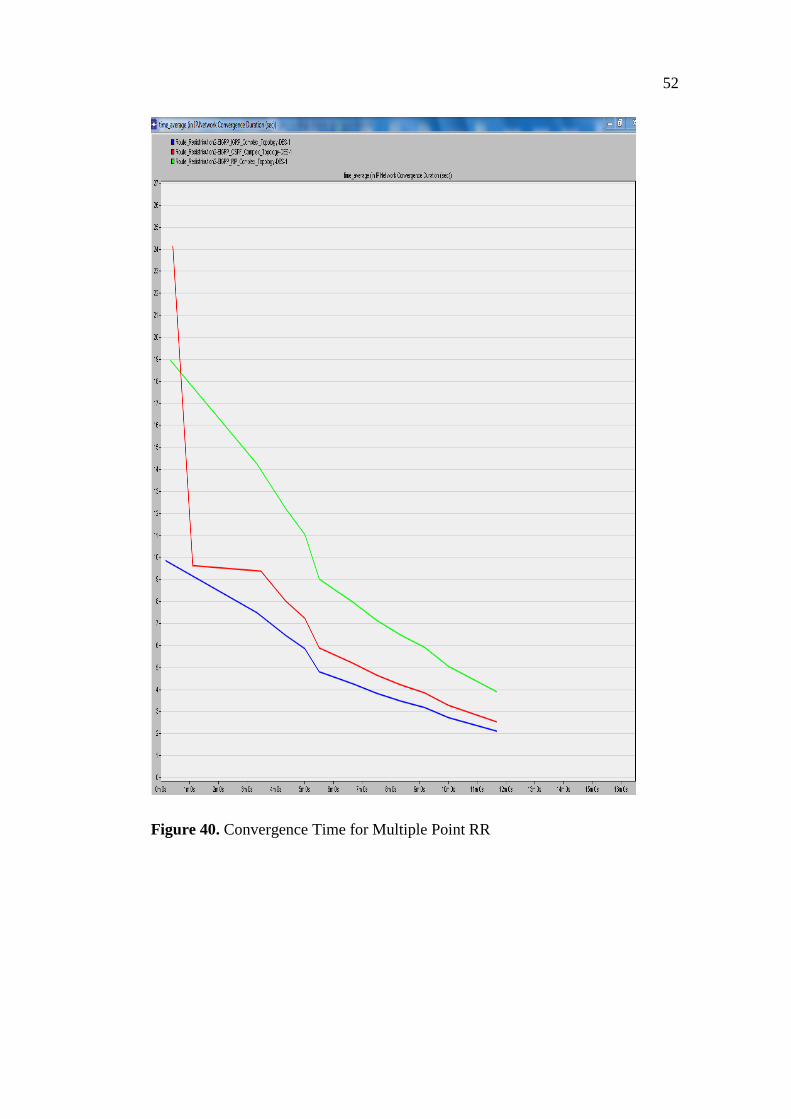
Figure 40. Convergence Time for Multiple Point RR
53
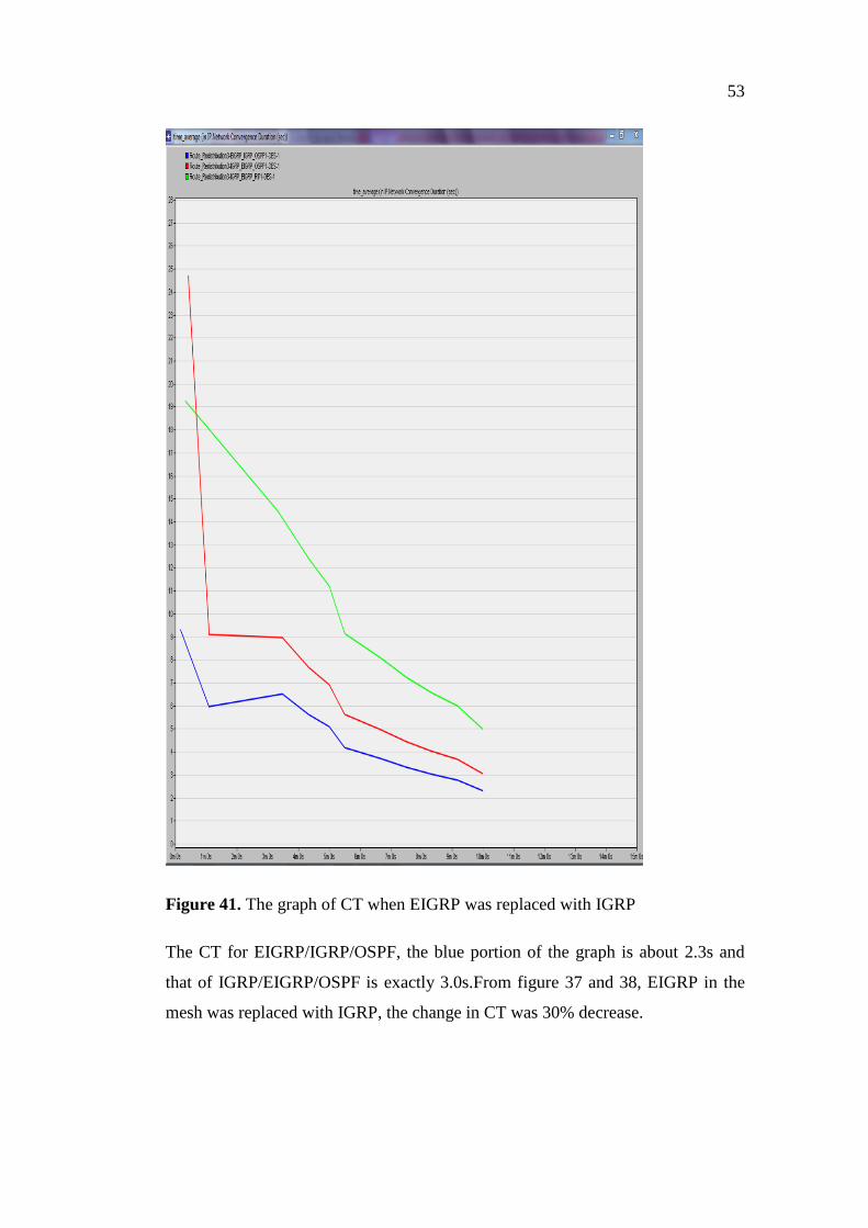
Figure 41. The graph of CT when EIGRP was replaced with IGRP
The CT for EIGRP/IGRP/OSPF, the blue portion of the graph is about 2.3s and
that of IGRP/EIGRP/OSPF is exactly 3.0s.From figure 37 and 38, EIGRP in the
mesh was replaced with IGRP, the change in CT was 30% decrease.
54
5.2 Analysis of ETE delay
The ETE delay for single point redistribution (figure 42), multiple point redistri-
bution (figure 43) were analyzed as seen below.
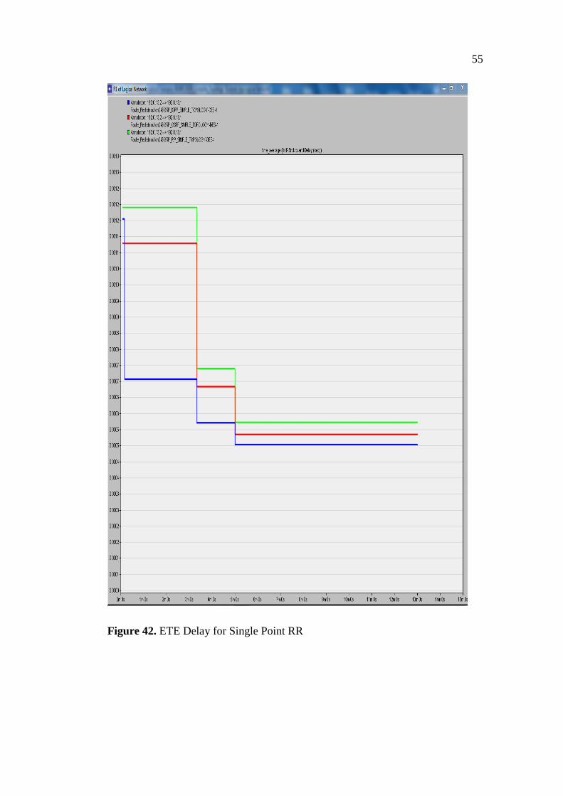
5.2.1 ETE Delay for Single Point RR
The blue line in figure 42 below indicates EIGRP/IGRP and the red line signifies
EIGRP/OSPF. The green line shows the graph of EIGRP/RIP. The vertical part of
the graph is the ETE delay in seconds, and the horizontal is the simulation time in
minutes. The three networks attain stability after about 5mins of simulation time.
The EIGRP/RIP remains most unstable networks within the 5mins of simulation.
EIGRP/IGRP is the least stable. EIGRP/IGRP has the least ETE delay and
EIGRP/RIP has the worst delay.
55
Figure 42. ETE Delay for Single Point RR
56
5.2.2 ETE Delay for Multiple Point RR
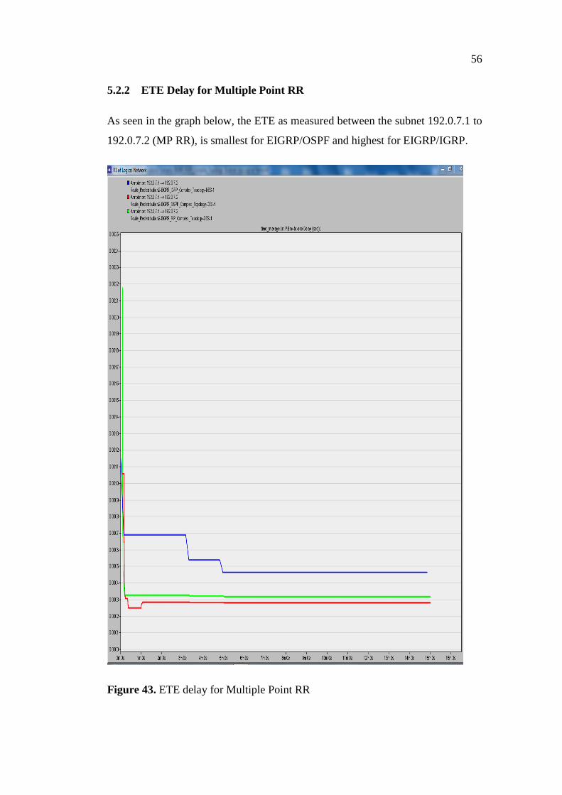
As seen in the graph below, the ETE as measured between the subnet 192.0.7.1 to
192.0.7.2 (MP RR), is smallest for EIGRP/OSPF and highest for EIGRP/IGRP.
Figure 43. ETE delay for Multiple Point RR
57
5.2.3 ETE Delay Variation
The analyses of ETE delay variation (jitter) for both SP and MP redistribution and
their graphs are shown in figure 44 and figure 45.
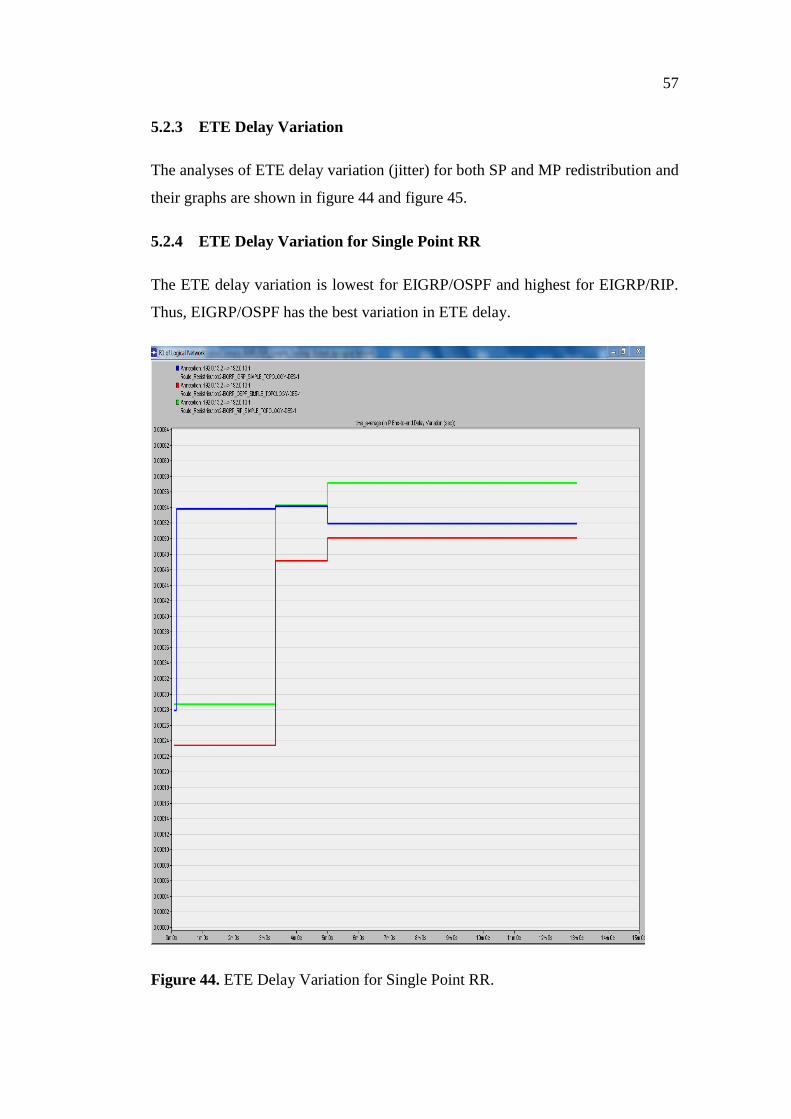
5.2.4 ETE Delay Variation for Single Point RR
The ETE delay variation is lowest for EIGRP/OSPF and highest for EIGRP/RIP.
Thus, EIGRP/OSPF has the best variation in ETE delay.
Figure 44. ETE Delay Variation for Single Point RR.
58
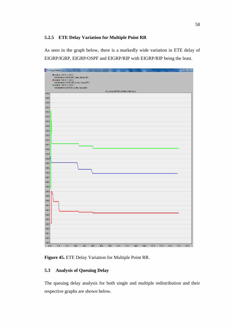
5.2.5 ETE Delay Variation for Multiple Point RR
As seen in the graph below, there is a markedly wide variation in ETE delay of
EIGRP/IGRP, EIGRP/OSPF and EIGRP/RIP with EIGRP/RIP being the least.
Figure 45. ETE Delay Variation for Multiple Point RR.
5.3 Analysis of Queuing Delay
The queuing delay analysis for both single and multiple redistribution and their
respective graphs are shown below.
59
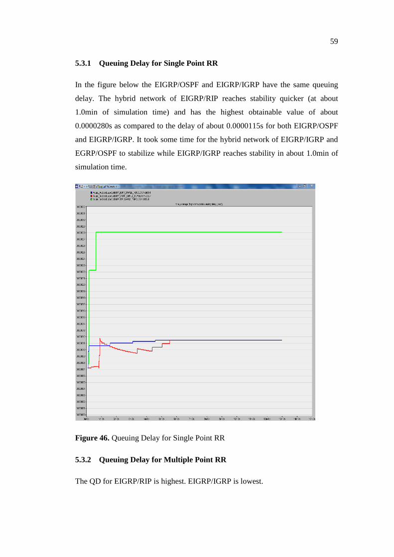
5.3.1 Queuing Delay for Single Point RR
In the figure below the EIGRP/OSPF and EIGRP/IGRP have the same queuing
delay. The hybrid network of EIGRP/RIP reaches stability quicker (at about
1.0min of simulation time) and has the highest obtainable value of about
0.0000280s as compared to the delay of about 0.0000115s for both EIGRP/OSPF
and EIGRP/IGRP. It took some time for the hybrid network of EIGRP/IGRP and
EGRP/OSPF to stabilize while EIGRP/IGRP reaches stability in about 1.0min of
simulation time.
Figure 46. Queuing Delay for Single Point RR
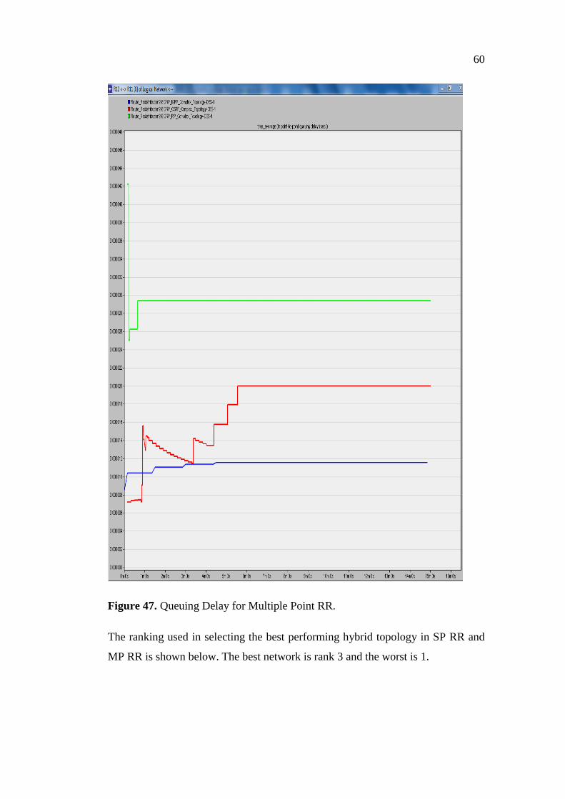
5.3.2 Queuing Delay for Multiple Point RR
The QD for EIGRP/RIP is highest. EIGRP/IGRP is lowest.
60
Figure 47. Queuing Delay for Multiple Point RR.
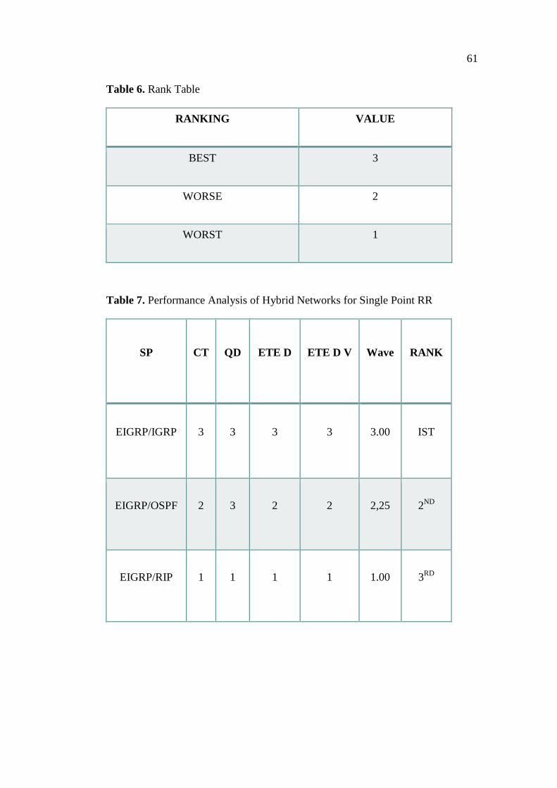
The ranking used in selecting the best performing hybrid topology in SP RR and
MP RR is shown below. The best network is rank 3 and the worst is 1.
61
Table 6. Rank Table
RANKING VALUE
BEST 3
WORSE 2
WORST 1
Table 7. Performance Analysis of Hybrid Networks for Single Point RR
SP CT QD ETE D ETE D V Wave RANK
EIGRP/IGRP 3 3 3 3 3.00 IST
EIGRP/OSPF 2 3 2 2 2,25 2ND
EIGRP/RIP 1 1 1 1 1.00 3RD
62
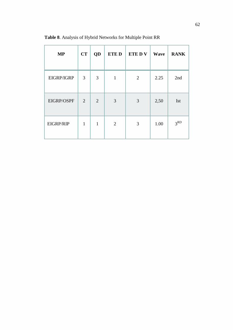
Table 8. Analysis of Hybrid Networks for Multiple Point RR
MP CT QD ETE D ETE D V Wave RANK
EIGRP/IGRP 3 3 1 2 2.25 2nd
EIGRP/OSPF 2 2 3 3 2,50 Ist
EIGRP/RIP 1 1 2 3 1.00 3RD
63
6 CONCLUSIONS
The route redistribution is still the most popular means of propagating routes be-
tween routing domains because its configuration is easy and flexible allowing the
support of numerous policy based scenarios. Nevertheless erroneous configuration
can create inconsistence convergence times and routing loops. /13/.
Since OPNET Modeler was the GUI, no configuration was done. It was used to
study how merged networks performed after performing route redistribution be-
tween them; these problems were not observed.
Another significance aspect of this thesis is the knowledge gained from OPNET
Modeler in designing network topologies , performing both single point and mul-
tiple point redistribution and the software use as an indispensable analytic tool for
computer networks.
New and important hybrid mesh-ring designs were proposed for merging net-
works. It was also observed that the network topology in which a given routing
protocol is configured can significantly affect the CT. Thus, the following deduc-
tions were arrived at:
RP performance is affected by the type of hybrid network topology as seen
in the 30% decrease in CT as EIGRP in mesh is replaced by IGRP for RR
between three routing domains
EIGRP/IGRP has the best performance in simple networks from a compo-
site analysis of convergence time, ETE delay, ETE delay variation (jitter),
and queuing delay.
EIGRP/OSPF performs best in complex networks.
The EIGRP/RIP performs poorest in both simple and complex networks.
64
In a hybrid topology of mesh –ring with EIGRP configured in a mesh and
one of each of OSPF, RIP and IGRP in a ring with RR at the border router
(ABSR), the hybrid network of EIGRP/IGRP has the fastest CT.
6.1 Future Work
The performance of these integrated networks will be thoroughly studied as their
topology changes. i.e. how will the network be affected (in terms of networks per-
formance metrics) as their different topologies are interchanged.
65
REFERENCES
/1/ Bahl, V. 2012. Performance Issues and Evaluation considerations of web
traffic for RIP & OSPF Dynamic Routing Protocols for Hybrid Networks Using
OPNET. Accessed 4/6/2014.
http://www.ijarcsse.com/docs/papers/9_September2012/Volume_2_issue_9/V2I9
00110.pdf
/2/ CCNA Explorer 2 Introduction to Dynamic Routing Protocols. Accessed
24/5/2014.
http://mars.tekkom.dk/mediawiki/index.php/CCNA_Explorer_2_Introduction_to_
Dynamic_Routing_Protocols
/3/ CCNP ROUTE Certification Guide: Basic IGP Redistribution. Accessed
26/5/2014.
http://www.ciscopress.com/articles/article.asp?p=1565876&seqNum=2
/4/ Cisco Networking Academy's Introduction to Routing Dynamically. Ac-
cessed 27/5/2014.
http://www.ciscopress.com/articles/article.asp?p=2180210&seqNum=4
/5/ Comparative Analysis of FIFO, PQ and WFQ. Accessed 24/5/2014.
http://www2.ensc.sfu.ca/~ljilja/ENSC427/Spring11/Projects/team2/ENSC427_Te
am2_Final_Report.pdf
/6/ Computer Networks. Accessed 11/2/2014. http://vfu.bg/en/e-
Learning/Computer-Networks--Networking.pdf
/7/ Daniele, P. Gnawal, O. Yoon, S. Santini, S. Colesanti, U. Giordano, S.
Guibas, L. The Impact of Network Topology on Collection Performance. Ac-
cessed 27/5/2014. http://www2.cs.uh.edu/~gnawali/end-ewsn10.pdf.
/8/ Enhanced Interior Gateway Routing Protocol. Accessed 22.5.2014.
http://www.routeralley.com/ra/docs/eigrp.pdf
/9/ GNS3-Topology: CCNA & CCNP Full Mesh Topology Template. Ac-
cessed 20/4/2014. http://www.gns3-labs.com/2008/12/01/gns3-topology-ccna-
ccnp-full-mesh-topology-template
/10/ Jorge, N.P. 2001.Accessed 22.5.2014.
http://upcommons.upc.edu/pfc/bitstream/2099.1/13043/6/Nicolas_Perez_Jorge___
final_thesis.pdf.txt
/11/ IGRP (Interior Gateway Routing Protocol). Accessed 22.5.2014.
http://www.routeralley.com/ra/docs/igrp.pdf
/12/ Kiavash, M. Nguyen , M. Elmasry, M. 2013. Final Report: Analysis of
RIP; OSPF and EIGRP Routing Protocols Using OPNET. Accessed 25/5/2014.
http://www.sfu.ca/~mtn9/427_Report.pdf
66
/13/ Le, F. Xie, G. Zhang, H. 2007. Understanding Route Redistribution
.Accessed 23.5.2014. www.cs.cmu.edu/~4D/papers/rr-icnp07.pdf
/14/ Mohammad, N. Nazrul, Ashique, U .2010. Simulation of EIGRP over
OSPF Performance Analysis. Accessed 23.5.2014.
http://www.bth.se/com/mscee.nsf/attachments/4983_Thesis_Report_pdf/$file/498
3_Thesis_Report.pdf
/15/ OSPF Design Guide. Accessed 2/3/2014.
http://www.cisco.com/c/en/us/support/docs/ip/open-shortest-path-first-ospf/7039-
1.html
/16/ Routing Protocols and Concepts CCNA Exploration Companion Guide.
Accessed 20/4/2014.
http://ptgmedia.pearsoncmg.com/images/9781587132063/samplepages/15871320
60.pdf
/17/ Route Selection in Cisco Routers. Accessed 20/4/2014.
http://www.cisco.com/c/en/us/support/docs/ip/enhanced-interior-gateway-routing-
protocol-eigrp/8651-21.html
/18/ Redistributing Routing Protocols. Accessed 20/4/2014.
http://www.cisco.com/c/en/us/support/docs/ip/enhanced-interior-gateway-routing-
protocol-eigrp/8606-redist.html
/19/ Routing Information Protocol. Accessed 20/4/2014.
http://www.routeralley.com/ra/docs/rip.pdf
/20/ Route Redistribution. Accessed 20/4/2014.
http://www.freeccnastudyguide.com/study-guides/ccna/ch4/4-6-route-
redistribution
/21/ RRPP Configuration Guide (Protected VLANs Not Supported) .Accessed
11/12/2013.
http://www.h3c.com/portal/Technical_Support___Documents/Technical_Docume
nts/Switches/H3C_S5500_Series_Switches/Configuration/Typical_Configuration
_Example/H3C_Low-End_and_Mid-
Range_IPv6_ES_CG%28V1.01%29/200812/622079_1285_0.htm
/22/ Russ, W. Alvaro, R. Don, S. 2000. EIGRP for IP: Basic Operation and
Configuration. Accessed 25/5/2014.
http://www.safariflow.com/library/view/EIGRP+for+IP:+Basic+Operation+and+
Configuration/9780321618146/chapter03.html#ch3lev1s
/23/ Suraj, G. Mangesh, M. Parag, D. Jawandhiya. P. M. 2013 . Open-Source
Network Simulation Tools: An Overview. Accessed 24/2/2014.
http://ijarcet.org/wp-content/uploads/IJARCET-VOL-2-ISSUE-4-1629-1635.pdf

67
/24/ The Practical OPNET® User Guide for Computer Network Simulation.
Accessed 28/5/2014. http://www.scribd.com/doc/122400880/The-Practical-
OPNET-User-Guide-for-Computer-Network-Simulation.
/25/ Todorovic I, Scpanovic, S. 2011. Measurement of Routing Protocol for
RIP and EIGRP. Accessed 24/2/2014.
http://www.scripta.pmf.ac.me/volume2/ivana_todorovic.pdf
/26/ Zheng Lu and Hongji Yang. Accessed 11/12/2013. Unlocking the power
of OPNET Modeler http://www.scribd.com/doc/122401790/Unlocking-the-
power-of-OPNET-modeler


![JavaScriptWebCryptographyAPI - theseus.fi · 3 TheWebCryptographyAPI5 specificationisanewstandardproposalfromtheWeb CryptographyWorkingGroupoftheWorldWideWebConsortium(W3C)[29]thatprovides](https://img.pdfslide.net/doc/110x75/5c78c49a09d3f2990f8bae54/javascriptwebcryptographyapi-3-thewebcryptographyapi5-specificationisanewstandardproposalfromtheweb.jpg)