Embed Size (px)
Citation preview

. LA-13164-MSUC-741
Issued:Januay 1997
PBX 9501 High Explosive ViolentResponse/Low Amplitude Insult Project: Phase I
D,J. IdarR.A. LuchtR. ScammonJ. StraightC.B. Skidmore
LosAlamosNATIONAL LABORATORY
LosAlamos,NewMexico87545
TABLE OF CONTENTS
ABSTRACT ............................................................................................................................................ 1
I. INTRODUCTION ............................................................................................................................... 2
II. BACKGROUND ................................................................................................................................ 2
III. EXPERIMENTAL ........................................................................................................................... 3
A. SPIGOT GUN, PROJECTILEDESCRIPTION, AND POWDER CURVE TESTS .......................... 3
B. INERTTARGET DESCRIPTION .......................................................................................................5
C. LIVE TARGET I DESCRIPTION ....................................................................................................... 8
D. MILD STEELBACKING PLATE DESCRIPTION ......................................................................... 10
E. LIVE TARGET II DESCRIPTION .................................................................................................... 10
F. LIVE TARGET III DESCRIPTION ................................................................................................... 11
IV. DATAANALYSIS AND RESULTS ............................................................................................... 12
A. LIVE TARGET TESTS ..................................................................................................................... 12
B. FERRITE SCOPE MEASUREMENTS ............................................................................................ 13
C. INSTRUMENTED TARGET RESULTS .......................................................................................... 16
D. PRELIMINARY ANALYSIS OF DAMAGED PBX 9501 ...............................................................35
V. MODELING PROBLEM SET-UP 41
A. APPROACH ...................................................................................................................................41
B. IGNITION CRITERION ................................................................................................................... 41
VL MODELING ANALYSIS AND RESULTS .................................................................................. 43A. MATERIAL PROPERTIESAND CALIBRATION ..........................................................................43
B. CALCULATIONS .............................................................................................................................45
C. CARBON FOIL GAUGES.. ..............................................................................................................45
D. RADIAL PINDUCERS .....................................................................................................................47
E. REAR SURFACE PINDUCERS .......................................................................................................48
F. IGNITION CRITERION .................................................................................................................... 52
VII. EXPEFUMETALAND MODELING CONCLUSIONS ........................................................... 53A. EXPERIMENTAL ............................................................................................................................. 53
B. MODELING ...................................................................................................................................54
VIII. FUTURE OBJECTIVES ............................................................................................................ 54A. EXPERIMENTAL ............................................................................................................................. 54
B. MODELING ................................................................................................................................... 54
IX. ACKNOWLEDGMENTS ............................................................................................................. 55REFERENCES ..................................................................................................................................... 57DISTRIBUTION LIST ........................................................................................................................ 57
v
LIST OF TABLES
TABLE 1. POWDER CURVE PERFORMANCE RESULTS FOR LOW PRESSURE BARREL
DESIGN ............................................................................................................................. 6-8
TABLE 2. POWDER CURVE PERFORMANCE RESULTS FOR HIGH PRESSURE BARREL
DESIGN ................................................................................................................................. 9
TABLE 3. PBX 9501, LOT NUMBER HOL90C731, DENSITY REPORT ........................................... 9
TABLE 4. TARGET DENT DATA MEASURED ON ASSEMBLED AND DISASSEMBLED
TARGETS ............................................................................................................................ 13
TABLE 5. LIVE TARGET DATA SUMMARY ..................................................................................... 14
TABLE 6. DENSITY OF PBX 9501 CORE SAMPLES (g/cm3),POST TEST .................................... 38
TABLE 7. MATERIAL PROPERTIESUSED IN DYNA2D CALCULATIONS ................................. 44
LIST OF FIGURES
FIGURE 1. HOOP AND AXIAL STRAIN MEASUREMENTS OBTAINED FROM THE HIGH PR-ES-
SURE BARREL DESIGN FOR THE SPIGOT GUN .......................................................... 4
FIGURE 2. BORE PRESSURE AS A FUNCTION OF TIME FOR THE HIGH PRESSURE
BARREL DESIGN ...............................................................................................................4
FIGURE 3. SPIGOT GUN AND PHOTODIODE VELOCITY SCREEN BOX .................................... 5
FIGURE 4. LIVE TARGET DESIGN I .................................................................................................10
FIGURE 5. LIVE TARGET DESIGN II, WITH 18 FOIL SWITCHES, ONE CARBON FILM
GAUGE, AND 5 PINDUCERS ......................................................................................... 11
FIGURE 6. LIVE TARGET DESIGN III, WITH 14 FOIL SWITCHES, ONE THERMOCOUPLE,
AND 7 PINDUCERS .........................................................................................................12
FIGURE 7. FERRITE SCOPE MEASUREMENTS ON TARGET 3 FRAGMENTS, POST TEST,
AFTER INTENTIONAL DETONATION OF PBX 9501 .................................................. 15
FIGURE 8. FERRITE SCOPE MEASUREMENTS ON TARGET 5 HARDWARE, POST TEST .....15
FIGURE 9. KARL STAUDHAMME R’S FERRITE SCOPE DATA ON 304 SS ................................. 16
FIGURE 10. TARGET TEST 5 EXPERIMENTAL DATAAND DESIGN .................................... 17-18
FIGURE 11.TARGET TEST 6EXPERIMENTALDATAAN’D DESIGN ..................................... 19-20
FIGURE 12. TARGET TEST 7 EXPERIMENTAL DATAAN’D DESIGN .................................... 21-24
FIGURE 13. TARGET TEST 9 EXI?ERIMENTALDATA AND DESIGN .................................... 25-27
FIGURE 14. TARGET TEST 10 EXPERIMENTAL DATA AND DESIGN .................................. 28-31
FIGURE 15. ESTIMATED EXTENT OF PBX9501 REACTION AS A FUNCTION OF
PROJECTILEVELOCITY ..............................................................................................33
FIGURE 16. PBX 9501 TARGETS3 AND 4 ........................................................................................36
FIGURE 17. PBX 9501 TARGETS 6 AND 8 ........................................................................................ 37
FIGURE 18. MACHINED SURFACES OF PBX 9501 FROM TARGET TEST 8, POST TEST ........39
FIGURE 19. FRACTURE SURFACES OF PBX 9501 FROM TARGET TEST 8, POST TEST .........40
vi
FIGURE 20. LIGHT MICROSCOPE IMAGES OF A) COARSE HMX POWDER, B) THE MICRON
SCALE OF THE IMAGES, C) SAMPLE OF PBX 9501 FROM TARGET 1,AND
D) THE SAMPLE OF PBX 9501 FROM TARGET 9 .....................................................40
FIGURE 21. PBX 9501, RECOVERED FROM SEMIVIOLENT REACTION OF TARGET
TEST 9 .............................................................................................................................. 41
FIGURE 22. DYNA2D MESH USED TO MODEL SPIGOT GUN PROJECTILEIMPACT
ON PBX 9501 TARGET ..................................................................................................42
FIGURE 23. DISTORTED DYNA2D MESH FOR TARGET TEST 4 (DF15-2330) ........................... 42
FIGURE 24. STRESS-STRAIN DATA FOR 304 STAINLESS STEEL (304 SS) ................................ 43
FIGURE 25. COMPARISON OF CALCULA~D AND MEASURED FRONT DENT DEPTH
AND REAR SURFACE DEFORMATION .....................................................................44
FIGURE 26. AXIAL STRESS AT THE REAR SURFACE OF THE PBX 9501 AS A FUNCTION OF
RADIAL OFFSET FROM THE CENTER LINE, TARGET TEST 5 (DF15-2347) ........46
FIGURE 27. CARBON FOIL GAUGE DATA AND ,CALCULATIONS, TARGET TESTS 5
(DF15-2347) AND 6 (DF15-2368) ................................................................................... 46
FIGURE 28. CARBON FOIL GAUGE DATA AND CALCULATIONS, TARGET TEST 10
(K3.1304)...... .................................................................................................................... 47
FIGURE 29. TARGET TEST 4 (DF15-2330), RADIAL PINDUCER 4, EXPERIMENTAL
AND CALCULATED DATA ...........................................................................................48
FIGURE 30. TARGET TEST 5 (DF15-2347), PINDUCER 2, EXPERIMENTAL AND
CALCULATED DATA .....................................................................................................49
FIGURE 31. TARGET TEST 5 (DF15-2347), PINDUCER 3, EXPERIMENTAL AND
CALCULATED DATA .....................................................................................................49
FIGURE 32. TARGET TEST 6 (K3-2368), PINDUCER 2, EXPERIMENTAL AND
CALCULATED DATA .....................................................................................................50
FIGURE 33. TARGET TEST 7 (K3-1235), PINDUCER 3, EXPERIMENTAL AND
CALCULATED DATA .....................................................................................................50
FIGURE 34. TARGET TEST 9 (K3-1290), PINDUCER 3, EXPERIMENTAL AND
CALCULATED DATA .....................................................................................................51
FIGURE 35. TARGET TEST 10 (K3-1304), PINDUCER 3, EXPERIMENTAL AND
CALCULATED DATA .....................................................................................................51
FIGURE 36. POWER LAW CRITERION PREDICTIONS FOR VARIOUS PROJECTILE RADII ..52
FIGURE 37. CALCULATED PRESSURE AT IGNITION CRITERION, WORST-CASE
LOCATION, TARGET TEST 5 (DF15-2347) ................................................................ 53
vii
PBX 9501 HIGH EXPLOSIVE VIOLENT RESPONSE/LOW AMPLITUDE INSULT PROJECT: PHASE I
by
D. J. Idar, R. A. Lucht, R. Scarnmon, J. Straight, and C. B. Skidmore
ABSTRACT
Preliminary modeling and experimental analyses of the violent reactionthreshold of semi-heavily confined PBX 9501 to low velocity impact havebeen completed. Experimental threshold measurements were obtained withten tests using a spigot gun design to launch a hemispherical projectile at thehigh explosive contained in stainless steel. Powder curves were determinedfor several gun barrel designs, powders, and projectile materials and haveproven to be very reproducible over the range of 75 to 325 Ms. A thresholdvelocity of approximately 246 ft/s for violent reaction of the PBX 9501 wasdetermined with experimental gauge and switch measurements and theremaining physical test evidence. Preliminary analyses of the PBX 9501samples retrieved from both unreacted and partially reacted targets have beencompleted. Core samples were obtained from the unreacted targets andsubmitted for density determinations. The subsequent analysis supports theconcept that the PBX 9501 yields and fi-acturesunder the low velocitycompression event to expand and fill the annular gap in the target design.Samples of PBX 9501 from the partially reacted targets were examined withscanning electron microscope and light microscope techniques. Increasedevidence of mechanical twinning effects are noted in the HMX crystals fromthe partially reacted targets. Finite element calculations using DYNA2D,with a modified ORION post processor, without reaction or chemistrymodels, were used to support the design of targets, to compare predictiveanalyses with experimental measurements, and to evaluate a proposedignition criterion in a power law form for threshold to reaction with depen-dence on pressure, maximum shear strain rate, and time variables. Thecalculations show good agreement with the physical dent and deformationdata from the remaining target evidence; however, they do not match theexperimental pressure gauge measurements well. The differences can beattributed to a combination of the experimental variables, the need for bettermaterials properties values in the calculations, and the need for chemistryand reaction in the predictions. Also, further evaluation of the ignitioncriterion form is needed to account for the probability of fracture in thePBX 9501.
I. INTRODUCTION
Strong shock-to-detonation-transition (SDT) of high explosives (HE) has been well characterized overseveral decades in shock wave physics research and finite element and hydrodynamic code analyses.These initiation mechanisms are normally associated with impacts of relatively high velocities, 21 mm/ps, and pressures, 210 kbars. More recently, the focus of energetic materials research has shifted todetermining, defining, and predicting the phenomena associated with relatively weak, low amplitudeinsults and the probability for violent reaction leading to property damage and casualties.
These HE safety concerns are focused on the storage, handling, transport, and inadvertent initiation ofconventional and nuclear weapons, and methods related to disposal, dismantlement, and replacement.Examples of these events include the impact experienced by a weapon if it is accidentally dropped, or thecollision of a projectile with a weapon in storage or transport. Under these conditions the potential existsto either sensitize the HE or to produce a violent reaction with a possible loss of life and property. Thegoal is to identi~ the relevant parameters: mechanical, chemical, confinement, and impact conditions thatlead to sensitization, initiation, and/or violent reaction of the HE. This knowledge will assist in thedevelopment and verification ofourpredictive code capabilities. This knowledge will be used to estab-lish and modifi those methods associated with the safety issues.
PBX 9501, a LANL formulation, was chosen for our research because it represents a large portion of theHE in the remaining nuclear stockpile. It is a 95.0/2.5/2.5 wt ‘%. HNLWEstane/BDNPA-BDNPFformulat-ion’ with a theoretical maximum density (TMD) of 1.860 g/cm3and a nominal detonation velocity of8.83 mn+sec. The average density of the samples used for the research reported here was 1.837 g/cm3(-98.7% TMD).
The LLNL DYNA2D finite element code was chosen to support the modeling effort. This includedexperiment design calculations, material model development, and analysis of the experimental results.This code was also used to investigate the PBX 9501 ignition criterion developed by Richard Browning.
H. BACKGROUND
Recently Steven Chidester et al.z reported on their experimental and theoretical DYNA2D analyses of lowpressure impacts on the explosives LX-10-1 and LX-17-O. Their methodology, based on frictional workfor ignition, was used to predict the projectile threshold velocity to produce a violent event in the LX-lO-1. However, they were unable to obtain a reaction in the LX-17 under their experimental conditions.
The explosive LX-10-1 is a LLNL formulation with 94.5/5.5 wt % HMX/Viton A3with a TMD of 1.895g/cm3andanominal detonation velocity of 8.85 rndps. The critical temperatures of LX-10-l and PBX9501 are essentially the same, 215°C, and the drop weight impact heights differ little. However, they dodiffer in their skid, Susan, and spigot test (a different test than described in this report) results, with LX-10-1 showing more sensitivity. Fortheirresearch, Chidester and coworkers used LX-10-1 samples withan average density of 1.86 g/cm3(=98.2’XOTMD).
The explosive LX-17-O is also a LLNL formulation with 92.5/7.5 wt % TATB/Kel-F 800 with a TMD of
1.944 g/cm3and a nominal detonation velocity of 7.63 mrrd~s. The average density of their samples was1.90 g/cms (-97.77. TMD).
For their impact tests, Chidester et. al. employed a 2.56 kg, hemispherical nose, tantalum (Ta) projectilewith a 0.46 kg sabot launched from a smooth bore 76-mm diam. gas gun at a LX-10-1, metal encased,plane geometry target. They measured V,Ovalues for this arrangement ranging from -1 06.0–115.8 ft/s(32.3-35.3 rrh), which produced explosions. For comparison, a velocity of 1750 R/s (533 rids) is re-quired to produce an SDT 0.5-in. run-to-detonation in PBX 9501 with a flat, mild steel plate impact basedon I-D Hugoniot3matching calculations and the PBX 9501 Pop plot. Significantly higher velocitieswould be required for SDT driven by a hemispherical impactor because the shock waves produced wouldbe highly divergent. Similar tests by Chidester et. al. on LX-17-Oencased targets and with a projectilevelocity as high as 463.3 ft/s (141.2 m/s) did not produce a violent reaction.
III. EXPERIMENTAL
A. Spigot Gun, Projectile Description, and Powder Curve TestsThe projectile characteristics required by this project were a 2 kg projectile of arbitrary size and shapetraveling at velocities from 75 ft/s to 325 ft/s (=22 to 100 rrds). The arbitrary size and shape limited theutility of a conventional projectile-in-tube launch system, which would have required an elaborate sabotdesign and a massive sabot stripper. Although a gas driven system would have worked well for the 75 ft/s, it would have had trouble achieving the 325 fds needed.
For these reasons, a powder gun driving a spigot projectile was designed with the use of either BLC2 orIMR 4350 rifle powder. A small bore diameter was needed to burn the gunpowder reliably at highpressures. A small bore diameter and short barrel were also needed to achieve the very low 75 ft/s. Theinitial design had a 0.5-in. diam. bore with a 9-in. long barrel. For simplicity, a rimmed rifle cartridge(.45-70 cal.) is used. A 1.5-in. long polyethylene obturator is used to seal thepowdergas products. Theprojectile has a head of arbitrary size and shape driven by a 0.5-in. diam. by 5.25-in. long shank (spigot).The current projectile has a 3-in. diam. hemispherical nose, is made of cold rolled mild steel, and has atotal mass (with spigot) of2 kg. The gases are vented before the projectile leaves the bore to reduce tip-off. This gun worked well at low velocities, but the spigot buckled in-bore at higher velocities. Thus, thedesign was modified to a 0.75-in. bore still using the 0.45-70 cal cartridge. The new barrel has a 2-in. ODand is made of mild steel. The receiver or breech block has a 4-in. OD and is also made of mild steel.The barrel screws into the breech block with an Acme thread.
Because the projectile is so massive (compared to normal rifle bullets), the powder burns almost as if itwas in a closed container. As such, the burn characteristics do not match any published data, and com-puter code predictions are of little value. Thus, we have made some attempts to measure the burn pres-sure using piezoelectric pressure transducers. We have consistently overranged the 100,000 psi (-689MPa) transducers and have, on several occasions, literally blown them out the side of the barrels. Wehope to pursue these pressure measurements next year. Even with the 0.75-in. diam. spigot, we see plasticdeformation of the base of the spigot at velocities above -250 fth. We have achieved over 300 ft/s usinghardened spigots. In an attempt to reach 330 ft/s, we ruptured a barrel. Higher velocities required athicker, higher strength barrel. At this time, the powder weight vs. velocity curve for the 2-in. barrel iswell established, and the gun is performing reliably. A total of 71 tests has been fired with the 0.75-in.bore gun. Different barrels have slightly different powder curves due to small manufacturing variances.
A higher pressure barrel has been designed and fabricated, and initial testing has been completed. The
3
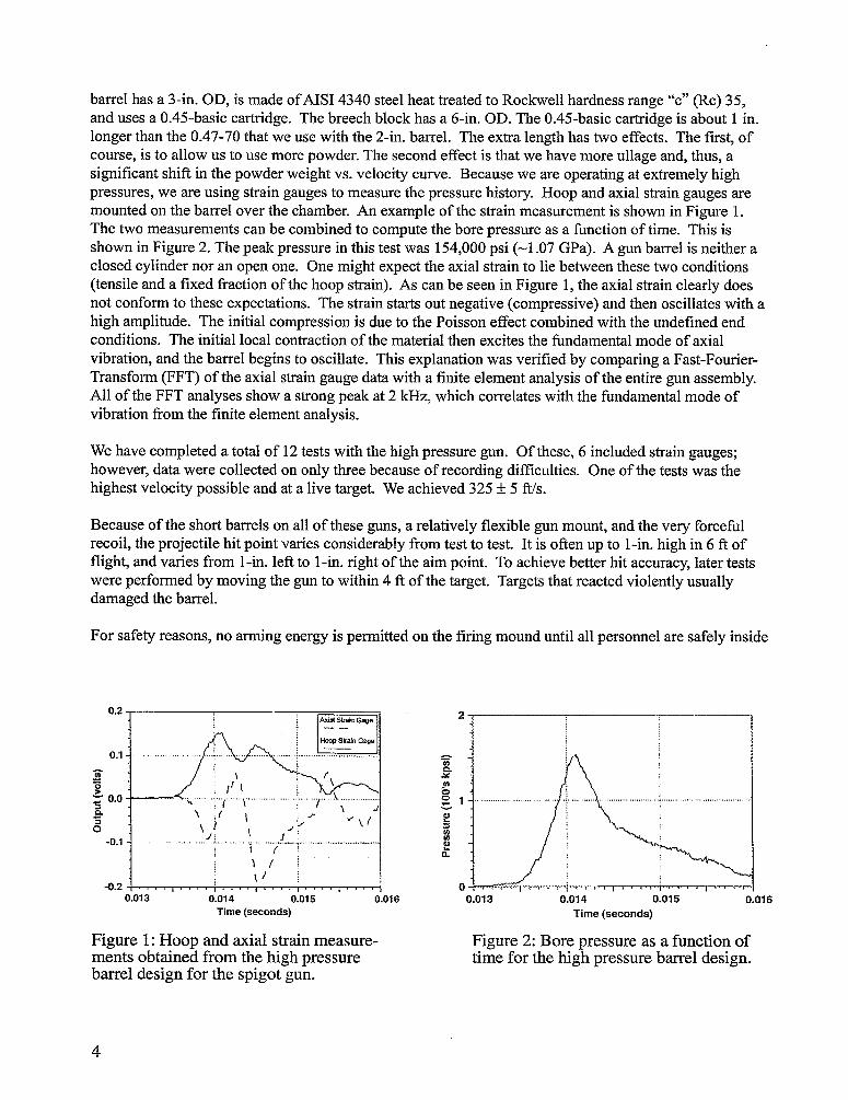
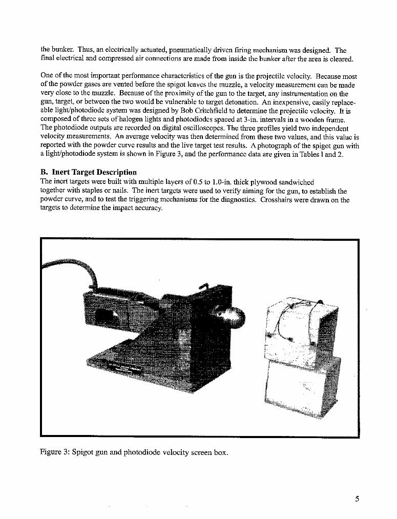
barrel has a 3-in. OD, is made of AISI 4340 steel heat treated to Rockwell hardness range “c” @c) 35,and uses a 0.45-basic cartridge. The breech block has a 6-in. OD. The 0.45-basic cartridge is about 1 in.longer than the 0.47-70 that we use with the 2-in. barrel. The extra length has two effects. The first, ofcourse, is to allow us to use more powder. The second effect is that we have more ullage and, thus, asignificant shift in the powder weight vs. velocity curve. Because we are operating at extremely highpressures, we are using strain gauges to measure the pressure history. Hoop and axial strain gauges aremounted on the barrel over the chamber. An example of the strain measurement is shown in Figure 1.The two measurements can be combined to compute the bore pressure as a function of time. This isshown in Figure 2. The peak pressure in this test was 154,000 psi (-1.07 GPa). A gun barrel is neither aclosed cylinder nor an open one. One might expect the axial strain to lie between these two conditions(tensile and a fixed &action of the hoop strain). As can be seen in Figure 1, the axial strain clearly doesnot conform to these expectations. The strain starts out negative (compressive) and then oscillates with ahigh amplitude. The initial compression is due to the Poisson effect combined with the undefined endconditions. The initial local contraction of the material then excites the fundamental mode of axialvibration, and the barrel begins to oscillate. This explanation was verified by comparing a Fast-Fourier-Transform (FFT) of the axial strain gauge data with a finite element analysis of the entire gun assembly.All of the FFT analyses show a strong peak at 2 kHz, which correlates with the fimdamental mode ofvibration tlom the finite element analysis.
We have completed a total of 12 tests with the high pressure gun. Of these, 6 included strain gauges;however, data were collected on only three because of recording difficulties. One of the tests was thehighest velocity possible and at a live target. We achieved 325+5 Ws.
Because of the short barrels on all of these guns, a relatively flexible gun mount, and the very forcefilrecoil, the projectile hit point varies considerably fi-omtest to test. It is often up to l-in. high in 6 ft offlight, and varies from l-in. left to l-in. right of the aim point. To achieve better hit accuracy, later testswere performed by moving the gun to within 4 R of the target. Targets that reacted violently usuallydamaged the barrel.
For safety reasons, no arming energy is permitted on the firing mound until all personnel are safely inside
0.013 0.014 0.015 0.016 0.013 0.014 0.015 0.016Time (seconds) Time (seconds)
Figure 1: Hoop and axial strain measure- Figure 2: Bore pressure as a function ofments obtained from the high pressure time for the high pressure barrel design.barrel design for the spigot gun.
4
the bunker. Thus, an electrically actuated, pneumatically driven firing mechanism was designed. Thefinal electrical and compressed air connections are made from inside the bunker after the area is cleared.
One of the most important performance characteristics of the gun is the projectile velocity. Because mostof the powder gases are vented before the spigot leaves the muzzle, a velocity measurement can be madevery close to the muzzle. Because of the proximity of the gun to the target, any instrumentation on thegun, target, or between the two would be vulnerable to target detonation. An inexpensive, easily replace-able lightiphotodiode system was designed by Bob Critchfield to determine the projectile velocity. It iscomposed of three sets of halogen lights and photodiodes spaced at 3-in. intervals in a wooden frame.The photodiode outputs are recorded on digital oscilloscopes. The three profiles yield two independentvelocity measurements. An average velocity was then determined fi-omthese two values, and this value isreported with the powder curve results and the live target test results. A photograph of the spigot gun witha light/photodiode system is shown in Figure 3, and the performance data are given in Tables 1and 2.
B. Inert Target DescriptionThe inert targets were built with multiple layers of 0.5 to l. O-in.thick plywood sandwichedtogether with staples or nails. The inert targets were used to verify aiming for the gun, to establish thepowder curve, and to test the triggering mechanisms for the diagnostics. Crosshairs were drawn on thetargets to determine the impact accuracy.
Figure 3: Spigot gun and photodiode velocity screen box.
5
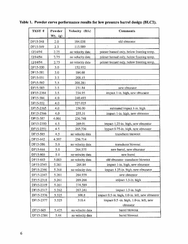
Table 1. Powder curve performance results for low pressure barrel design (BLC2).
TEST # Powder Velocity (ft/s) Comments
wt. (g)
DF15-548 ~.) 104.038 old obturator
DF15-549 2.5 115.989
12/]4/’J4 y2.75 no velocit dzttu primerburnedonly,belowfreezingtemp.
12/14/94 2.75 no vebcity data primerburnedon]y, belowfreezingtemp.
12/14/94 2,75 no velocitydata primerburnedonly,belowfreezingtemp.
DF15-550 3.0 152.932
DF15-581 3.0 184.68
DF15-551 3.5 208.15
DF15-582 3.5 205.281
DF15-583 3.5 231.84 new obturator
DF15-2364 3.5 234.95 impact“1-in.high,newobturator
DP15-584 4.0 240.493
DF15-552 4.0 227.025
DF15-2365 4.0 ~56.oo estimatedimpactl-in. high
DF15-2366 4.0 255.31 impact l-in. high,newobturator
DF15-587 4.001 236.748
DF15-2350 p4.5 269.01 im act 1.25-iu.high,uewobturator
DF15-2351 4.5 265.726 impact0,75-in.high,new obturator
DF15-585 4.5 no velocitydata transducerblowout
DF15-642 4.507 256.714
DF15-586 5.0 no velocitydata transducerblowout
DF15-644 5.0 264.575 newbarrel.new obturator
DF15-803 5.0 novelocitydata new bamel
DF15-643 5.003 no velocitydata old obturator-transducerblowout
DF15-2345 5.261 264.84 impact l-in. high,newobturator
DF15-2346 5.261 no velocitydata impact 1.25-in.high,new obturator
DF15-2,347 5.261 264.939 new obturator
DF15-2318 5.261 269.266 im’pac(1.5-in.high
DF15-2319 5.261 278.589
DF15-2317 5.262 267.241 impact 1.5-in.high
DF15-2376 5.325 308.8 impact0.5-in. high, 1.O-in.left,new obturator
DF15-2377 5.325 310.4I
impact0.5 -in. high, 1.O-in.left, newobturator
DF15-665 5,425 no velocitydata barrelblowout
DF15-2384 5.44 no velocitydata barrelbiowout
6

Table 1. Powder curve performance results for low pressure barrel design (IMR4350).
7
u) Optical sight was adjusted between tests, thus the hit point data is of little SignifkanCe.
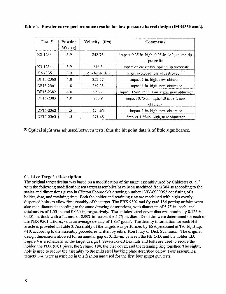
Table 1. Powder curve performance results for low pressure barrel design (IMR4350 cont.).
Test # Powder Velocity (ft/s) Comments
wt. (g)
1<3-1233 3.9 248.76 impact0.25-in. high, 0.25-in. left, spikd tip
K3-1234 3.9 246.3 impactcmcrosshairs,spikedtip projcctik
K3-1235 3.9 no velocitydata targetexploded,btirreldestroyed “)
DP15-2360 4.0 ~5~.57 impact l-in. high, new obturator
DF15-2361 4.0 249.23 impact i-in. high, new obturator
DF15-2382 4.0 256.7 impact0.5-in. high, I-in. righl, new obturzdor
DF15-Z383 4.0 253.9 impact0.75-in. high, 1,.()in left, new
obturator
DF15-2362 4.5 274.65 impact l-in. high, new obturator
DF15-2363 4.5 271.48 impact 1.25-in.high, new obturator
(1)Optical sight was adjusted between tests, thus the hit point data is Of little significance.
C. Live Target I DescriptionTheoriginal target design was based on a modification of the target assembly used by Chidester et. al.zwith the following modification: ten target assemblies have been machined from 304 ss according to thescales and dimensions given in Clinton Shonrock’s drawing number 139Y-600005,4consisting of aholder, disc, and retaining ring. Both the holder and retaining ring are machined with eight evenlydispersed holes to allow for assembly of the target. The PBX 9501 and Sylgard 184 potting articles werealso manufactured according to the same drawing descriptions, with diameters of 5.75-in. each, andthicknesses of l.00-in. and 0.020-in, respectively. The stainless steel cover disc was nominally 0.125&O.001-in.thick with a flatness of 0.002-in. across the 5.75-in. diam. Densities were determined for each ofthe PBX 9501 articles, with an average density of 1.837 g/cm3. The density information for each HEarticle is provided in Table 3. Assembly of the targets was performed by ESA personnel at TA-16, Bldg.410, according to the assembly procedures written by either Ron Flury or Dick Scamrnon. The originaldesign dimensions allowed for an annular gap of O.125-in. between the HE O.D. and the holder I.D.Figure 4 is a schematic of the target design 1.Seven 1/2-13 hex nuts and bolts are used to secure theholder, the PBX 9501 piece, the Sylgard 184, the disc cover, and the retaining ring together. The eighthhole is used to secure the assembly to the mild steel backing plate described below. Four assemblies,targets 1-4, were assembled in this fashion and used for the first four spigot gun tests.
8
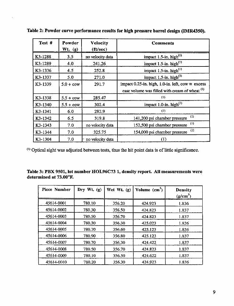
Table 2: Powder curve performance results for high pressure barrel design (IMR4350).
Test # I Powder I Velocity I Comments
K3-1288 I 3.5 I no veloeity data I impact 1.5-in. high(’)
K3-1289 I 4.0 I 241.26 I impact 1.5-in. high(l)
K3-1336 4.5 252.8 impact 1.5-in. high(’)
K3-1337 5.0 271.0 impact 1.5-in. high(])
K3-1339 5.0 + cow 291.7 impact 0.25-in. high, I.O-in. left, cow= excess
I I I case volume was filled with cream of wheat ‘1)
K3-1338 5.5 + cow 285.47 I (1)K3-1340 5.5 + cow 302.4 !
im act~-o-in hi h(l).t IK3-1341 I 6.0 I 282.9 I (1)
K3-1342 6.5 319.8 141,200 psi chamber pressure “)
K3-1343 7.0 no veloeity data 152,500 psi chamber pressure ‘[)
K3-1344 7.0 325.75 154,000 psi chamber pressure “)
K3- 1304 I 7.0 - no velocity data I (1)
(’)Optical sight was adjusted between tests, thus the hit point data is of little signtilcance.
Table 3: PBX 9501, lot number HOL96C73 1, density reporL All measurements weredetermined at 73.00”F.
‘ Piece Number Dry Wt. (g) Wet WL (g) Volume (cms) Density(g/cm3)
45614-0001 780.10 356.20 424.923 1.83645614-0002 780.30 356.50 424.823 1.83745614-0003 780.50 356.70 424.823 1.83745614-ooo4 780.30 356.30 425.023 1.83645614-0005 780.70 356.60 425.123 1.836
45614-0006 780.90 356.80 425.123 1.837
456144)(IO7 780.70 356.30 424.422 1.837
45614-0008 780.50 356.70 424.823 1.837
45614-0009 780.10 356.50 424.622 1.837
45614-0010 780.20 356.30 424.923 1.836
9