Embed Size (px)
Citation preview

1

2

3
This slide describes the paradigms of a database system that is reorganization free.
As MaxDB does not need to be reorganized, the database can be operated with minimal
administrative outlays.
The absence of the need to reorganize also means that the database always works with
optimal access structures. That means consistently good performance.
4
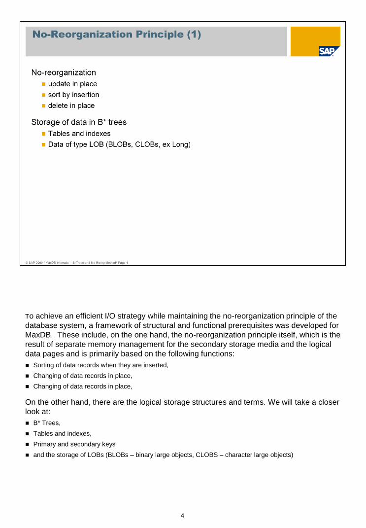
To achieve an efficient I/O strategy while maintaining the no-reorganization principle of the
database system, a framework of structural and functional prerequisites was developed for
MaxDB. These include, on the one hand, the no-reorganization principle itself, which is the
result of separate memory management for the secondary storage media and the logical
data pages and is primarily based on the following functions:
Sorting of data records when they are inserted,
Changing of data records in place,
Changing of data records in place,
On the other hand, there are the logical storage structures and terms. We will take a closer
look at:
B* Trees,
Tables and indexes,
Primary and secondary keys
and the storage of LOBs (BLOBs – binary large objects, CLOBS – character large objects)

5
The MaxDB storage concept ensures that data is quickly stored and found on the
available disks. It is the key to automatic load balancing by MaxDB and thus guarantees
the no-reorganization principle of the database system.
6
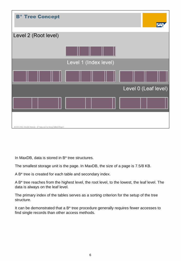
In MaxDB, data is stored in B* tree structures.
The smallest storage unit is the page. In MaxDB, the size of a page is 7.5/8 KB.
A B* tree is created for each table and secondary index.
A B* tree reaches from the highest level, the root level, to the lowest, the leaf level. The
data is always on the leaf level.
The primary index of the tables serves as a sorting criterion for the setup of the tree
structure.
It can be demonstrated that a B* tree procedure generally requires fewer accesses to
find single records than other access methods.

7
The entries in the data pages are comprised of two parts:
The fist part is comprised by the contents of the key fields of a table row. We shall refer to this as the separator.
The second part is comprised by the remaining data.
On index pages, every separator is followed by a logical address that refers to a page on a lower index
level or on the leaf level. The number of entries that fits on an index page depends on the length of the
separators.
A node of the B* tree always comprises one page. Thus the number of entries per B* tree level depends
on the length of the separators.
In addition to the separator, leaf pages contain the contents of the other columns of the respective table
row. The number of entries that fits on an index page depends on the length of the separators.
The amount of memory required for a table depends on the length of the key fields and the total length of
a table row.
The procedure described here is supplemented by special treatment of tables that contain LOB columns
(Large Objects). Additional auxiliary trees are created for the purpose of accepting the contents of LOB
columns, which can be many times longer than a data page.

8
The B* tree procedure makes it possible to find data quickly.
Here's an example of how a data record is found: looking in an address table with the primary index 'city', you want to find an entry for ‘Athens’.
The search begins on the root level. The comparisons described in the following take
place on a character by character basis.
The database system checks if the value 'Athens' is smaller than the second entry on
the root page, 'Baf'.
As the value is smaller, the corresponding logical address information from the first
branch is evaluated. It points to a page on the next level (index level).

9
The comparison then continues on the index level. Now the desired value, 'Athens', is
smaller than the entry 'Au' on the data page.
So the ‘An’ branch is evaluated.
The pointer points to the second page on the leaf level. Now we are on the leaf level
(level 0).

10
This page shows a root page as displayed by the MaxDB Tool x_diagnose.
At the top you see the page header. As the page number and root number on this page are
the same, this is a root page. The B* tree has three levels (levels 0 – 2). This page has
18 entries. It was changed 36 times.
The separators are shown in their alphanumeric order. You see the respective start
position, the page number on the next page to the separator, the length and the value of
the separator.
11
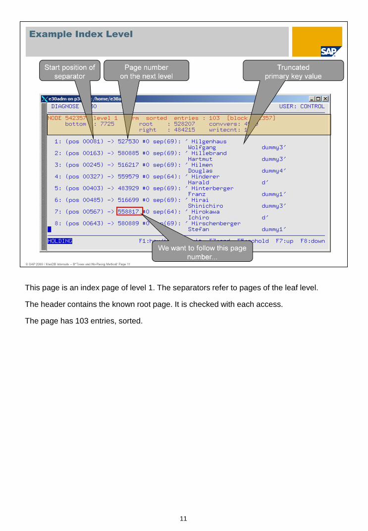
This page is an index page of level 1. The separators refer to pages of the leaf level.
The header contains the known root page. It is checked with each access.
The page has 103 entries, sorted.
12
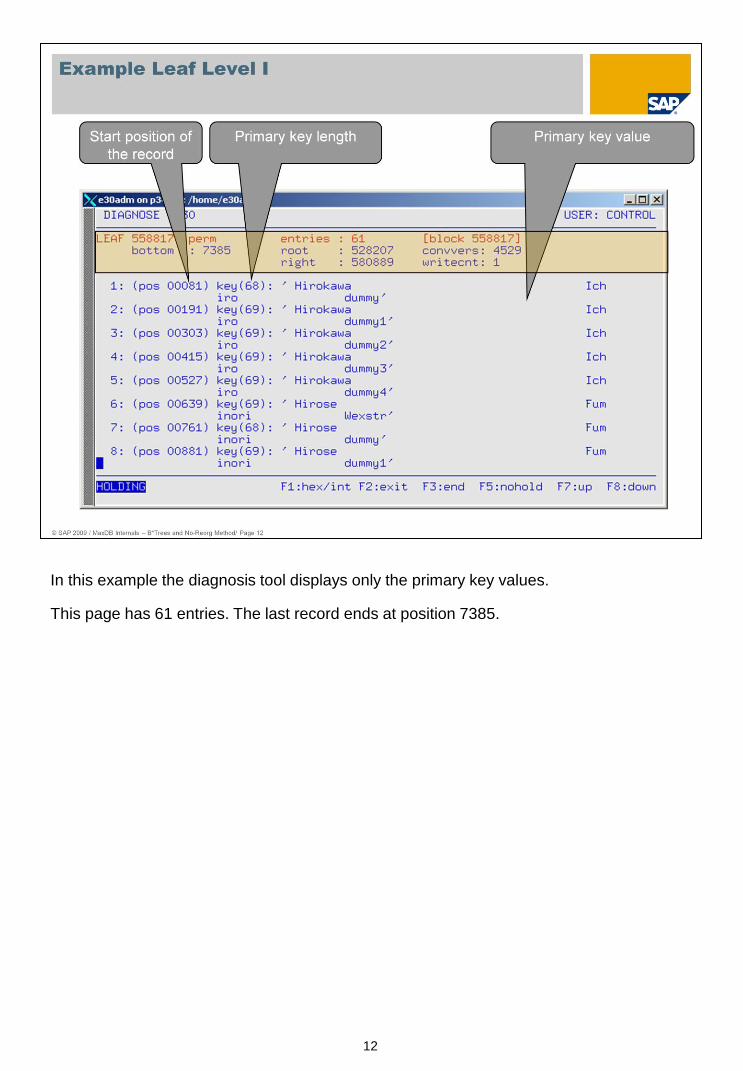
In this example the diagnosis tool displays only the primary key values.
This page has 61 entries. The last record ends at position 7385.
13
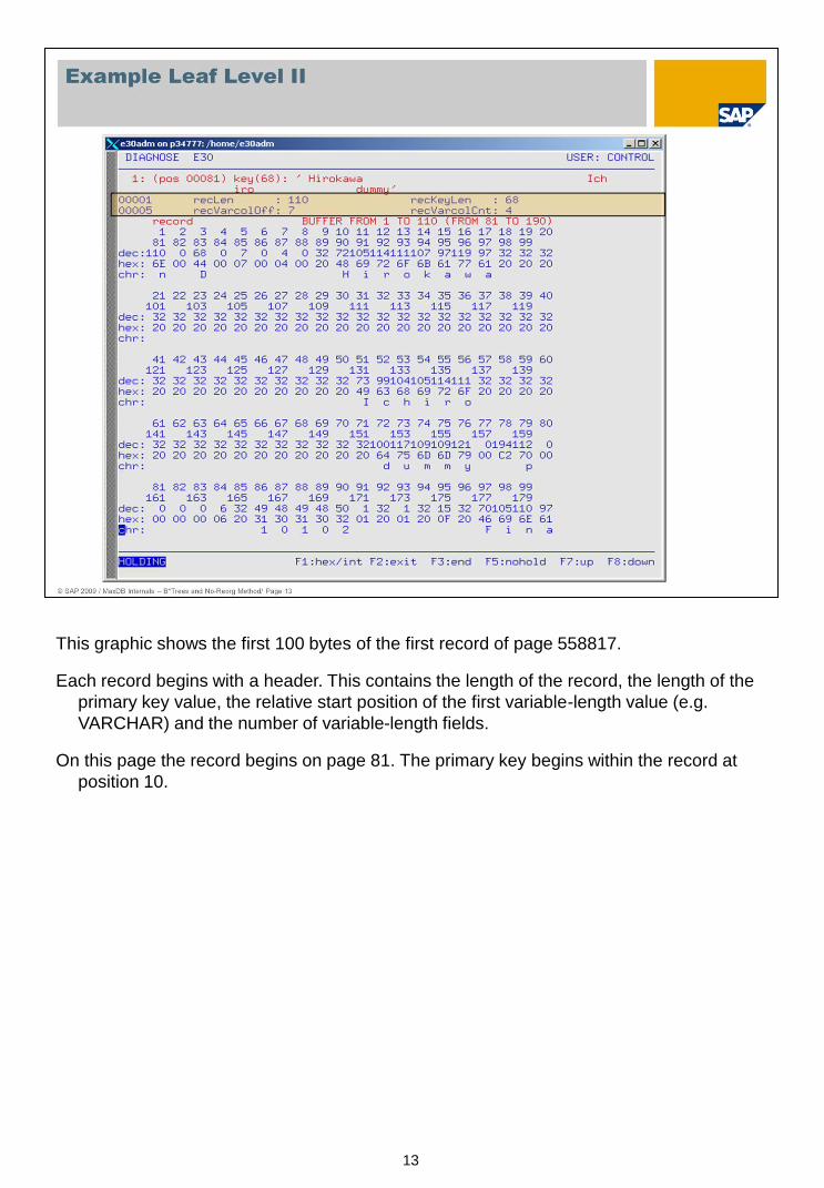
This graphic shows the first 100 bytes of the first record of page 558817.
Each record begins with a header. This contains the length of the record, the length of the
primary key value, the relative start position of the first variable-length value (e.g.
VARCHAR) and the number of variable-length fields.
On this page the record begins on page 81. The primary key begins within the record at
position 10.
14
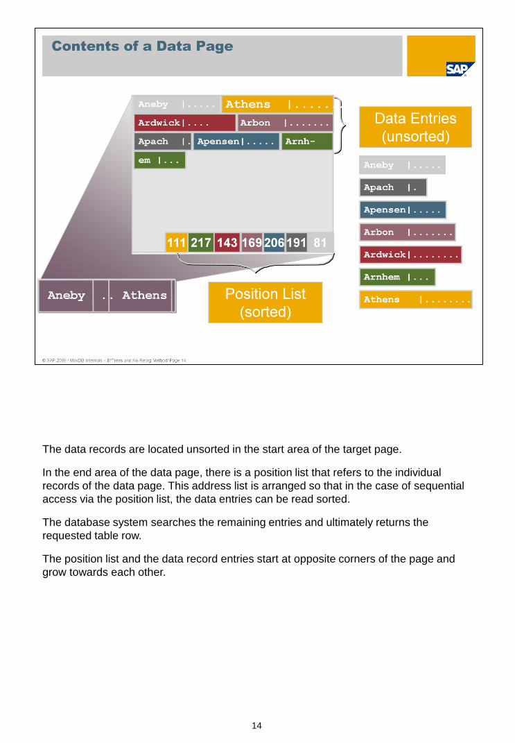
The data records are located unsorted in the start area of the target page.
In the end area of the data page, there is a position list that refers to the individual
records of the data page. This address list is arranged so that in the case of sequential
access via the position list, the data entries can be read sorted.
The database system searches the remaining entries and ultimately returns the
requested table row.
The position list and the data record entries start at opposite corners of the page and
grow towards each other.

15
If a record is to be inserted into the database or edited, MaxDB first searches for the
data page that is changed by the action. This is true for all the actions described in the
following. Then, if necessary, the required space is made available by way of clearing
operations.
sort by insertion
The records are:
inserted into the target page at the end of the used data area,
sorted in the position list via an entry that, in order to minimize the number of moved bytes, contains
only references to records.
The records in the data part are only sorted if a clearing operation becomes necessary.
If a data page is moved into another one, a sorted block is advantageous as this makes
it possible to move whole groups of records rather than copying record by record.
MaxDB data pages are organized such that the data area grows into the page from the
beginning and the sorting list from the end.
Let's assume that the record fits on the page. MaxDB simply puts it at the end of the
area available on the page...

16
... and then the position list is updated. The address of the new entry is written at the
correct position in the position list. In our case, the correct position is position 4, which accordingly points to the seventh data record, 'Arbon'.
17
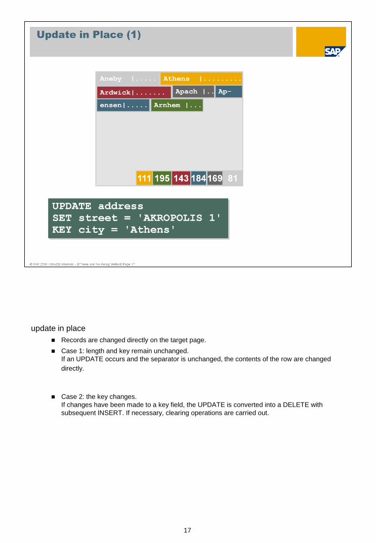
update in place
Records are changed directly on the target page.
Case 1: length and key remain unchanged.
If an UPDATE occurs and the separator is unchanged, the contents of the row are changed
directly.
Case 2: the key changes.
If changes have been made to a key field, the UPDATE is converted into a DELETE with
subsequent INSERT. If necessary, clearing operations are carried out.

18
Case 3: The length is changed, the key remains unchanged.
The contents of the row are changed directly, but the position of the subsequent entries is different. Thus
the subsequent records need to be moved and the address information (of the subsequent records)
adjusted in the position list. If necessary, clearing operations are carried out.
If it is necessary to change the tree structure, first the required space is made available by
way of B* tree clearing operations or by inserting a new block; then the UPDATE is carried
out as described.
19
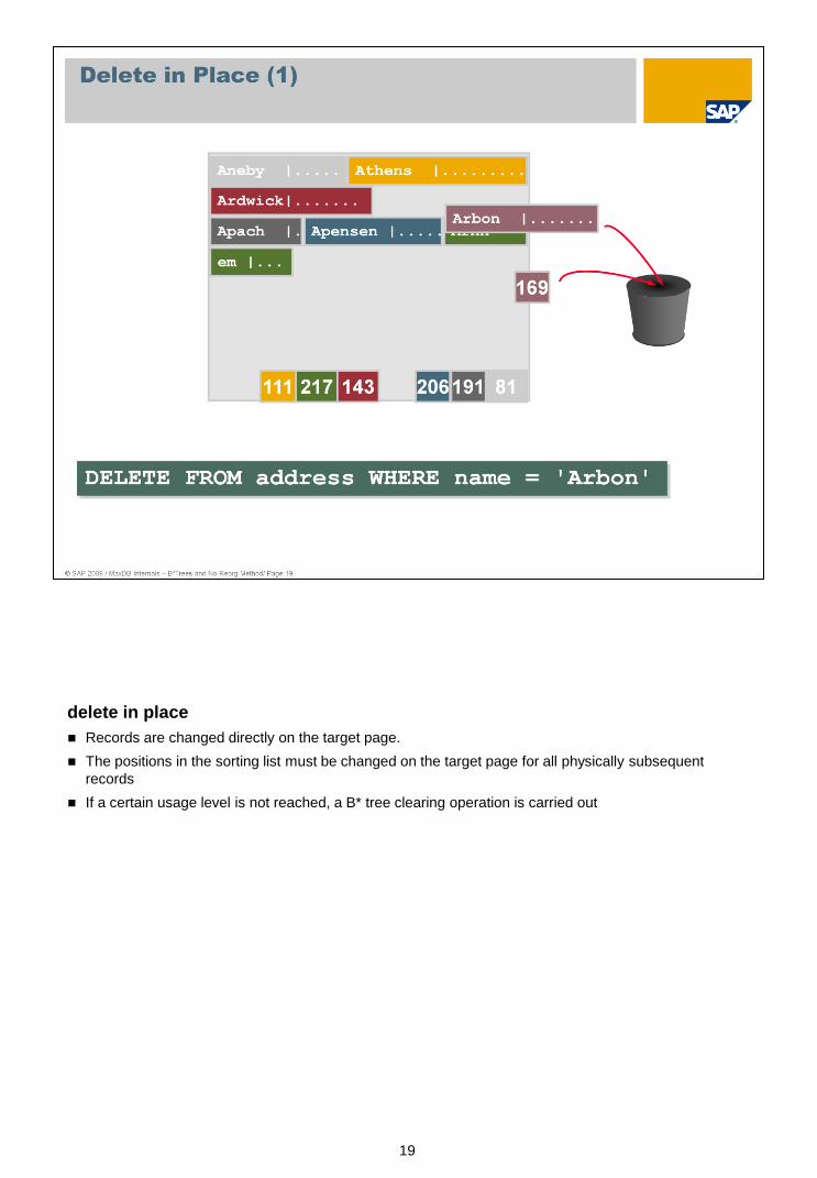
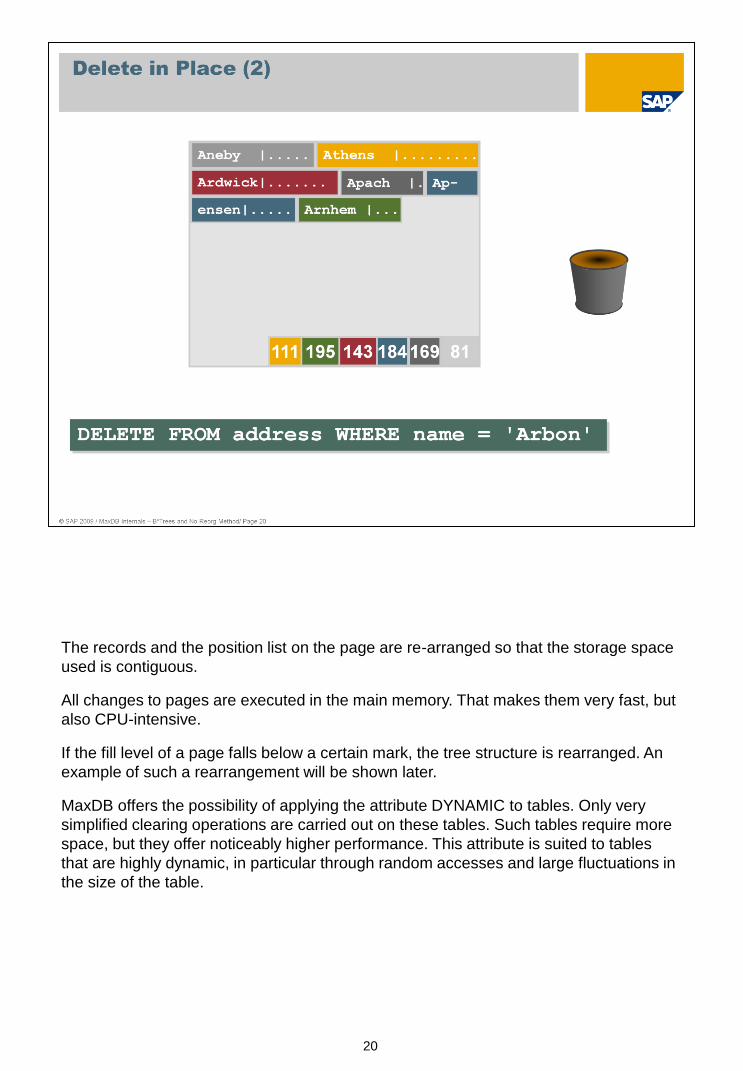
delete in place
Records are changed directly on the target page.
The positions in the sorting list must be changed on the target page for all physically subsequent
records
If a certain usage level is not reached, a B* tree clearing operation is carried out
20
The records and the position list on the page are re-arranged so that the storage space
used is contiguous.
All changes to pages are executed in the main memory. That makes them very fast, but
also CPU-intensive.
If the fill level of a page falls below a certain mark, the tree structure is rearranged. An
example of such a rearrangement will be shown later.
MaxDB offers the possibility of applying the attribute DYNAMIC to tables. Only very
simplified clearing operations are carried out on these tables. Such tables require more
space, but they offer noticeably higher performance. This attribute is suited to tables
that are highly dynamic, in particular through random accesses and large fluctuations in
the size of the table.

21
Now let's have a look at a simple change to the tree structure.
Let's assume that, due to an INSERT, the new data record no longer fits on the
corresponding page.
A new page is then created on which the new record and half of the data records from
the page that was too small for the INSERT are written. The respective records on the
original page are then deleted.

22
If necessary, the database system updates the pointers to the following pages.
In addition, the address and separator information for the new page is entered in the B*
index page above it.
If this also does not fit on the B* index page, a new page has to be inserted.
If the B* tree is no longer able to accept the new page, that is, even in the root page
there is no more space available in which to insert a new branch, the entire B* tree has
to be expanded by a new level.

23
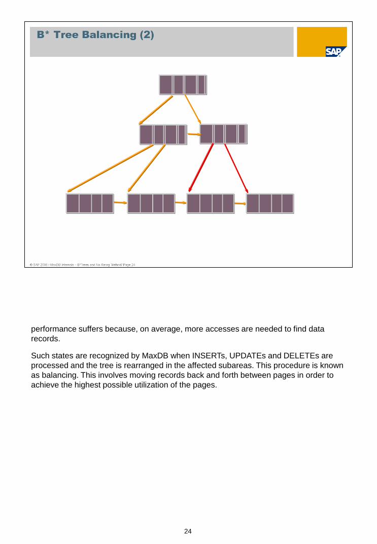
If the distribution of pages in the B* tree is unbalanced, that is, if there is an inordinate
amount of pages on certain branches of the tree,...
24
performance suffers because, on average, more accesses are needed to find data
records.
Such states are recognized by MaxDB when INSERTs, UPDATEs and DELETEs are
processed and the tree is rearranged in the affected subareas. This procedure is known
as balancing. This involves moving records back and forth between pages in order to
achieve the highest possible utilization of the pages.
25
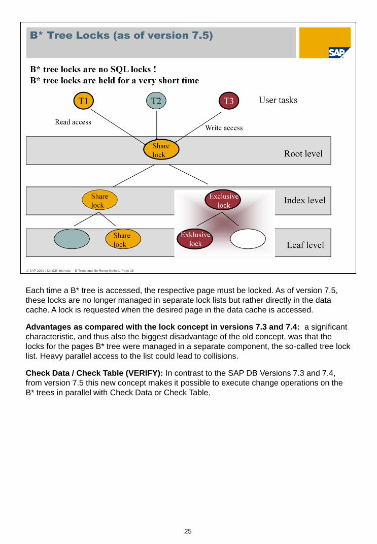
Each time a B* tree is accessed, the respective page must be locked. As of version 7.5,
these locks are no longer managed in separate lock lists but rather directly in the data
cache. A lock is requested when the desired page in the data cache is accessed.
Advantages as compared with the lock concept in versions 7.3 and 7.4: a significant
characteristic, and thus also the biggest disadvantage of the old concept, was that the
locks for the pages B* tree were managed in a separate component, the so-called tree lock
list. Heavy parallel access to the list could lead to collisions.
Check Data / Check Table (VERIFY): In contrast to the SAP DB Versions 7.3 and 7.4,
from version 7.5 this new concept makes it possible to execute change operations on the
B* trees in parallel with Check Data or Check Table.

26
MaxDB uses B* tree structures for the storage of all its tables.
The term "table" includes:
Primary data, including the associated LOB data (LOB Large Object)
Secondary data as required for single and multiple secondary keys.
A MaxDB table always has a primary key. This is either a user-defined key or a generated
internal key. A user-defined key can be comprised of several columns (multiple key).
The user can define additional secondary keys, which can also consist of one (single
index) or several (multiple index) columns.
There is exactly one B* tree for the primary data of a table and also precisely one B* tree
for each defined index (also known as: secondary key). If a table is defined with LOB
columns, one additional B* tree is created for the purpose of accepting the LOB values in
these columns that do not exceed a certain length. If LOB values are longer than this
defined value, a new B* tree is created for every single one of these values.
27
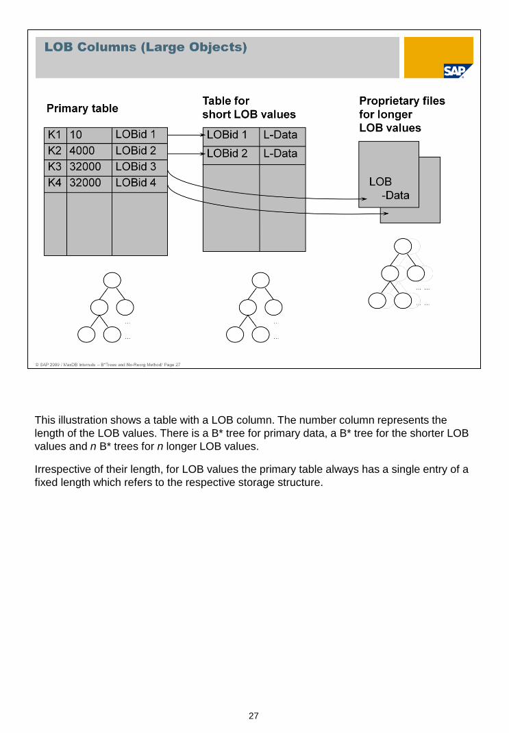
This illustration shows a table with a LOB column. The number column represents the
length of the LOB values. There is a B* tree for primary data, a B* tree for the shorter LOB
values and n B* trees for n longer LOB values.
Irrespective of their length, for LOB values the primary table always has a single entry of a
fixed length which refers to the respective storage structure.
28
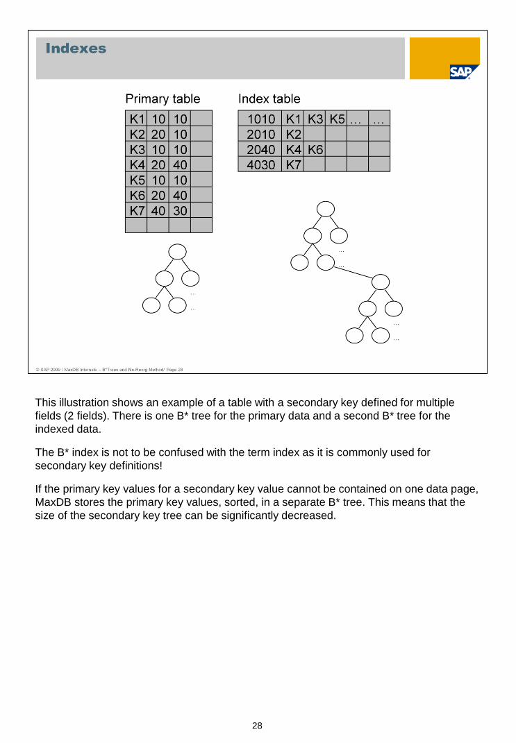
This illustration shows an example of a table with a secondary key defined for multiple
fields (2 fields). There is one B* tree for the primary data and a second B* tree for the
indexed data.
The B* index is not to be confused with the term index as it is commonly used for
secondary key definitions!
If the primary key values for a secondary key value cannot be contained on one data page,
MaxDB stores the primary key values, sorted, in a separate B* tree. This means that the
size of the secondary key tree can be significantly decreased.

29
This illustration, taking the example of a table that contains LOBs and for which a
secondary key has been defined, depicts how the assignment to B* tree structures works.

30
A table, which is known to the user by a name, is internally administered with a ‘tableid’.
The correlation between the names and tableids is registered in the database system
dictionary (catalog).
There is also the database file directory, which contains the assignments of the root
nodes of the B* trees to the tableids of the database objects. The tableids are stored in the
file directory along with a type flag which indicates what contents the underlying B* tree
has.
Thus a single tableid, in combination with the type flag, can be used to administer a table
with all its associated B* tree entries in the file directory.
The system table ROOTS contains information from the file directory and the database
catalog.
31
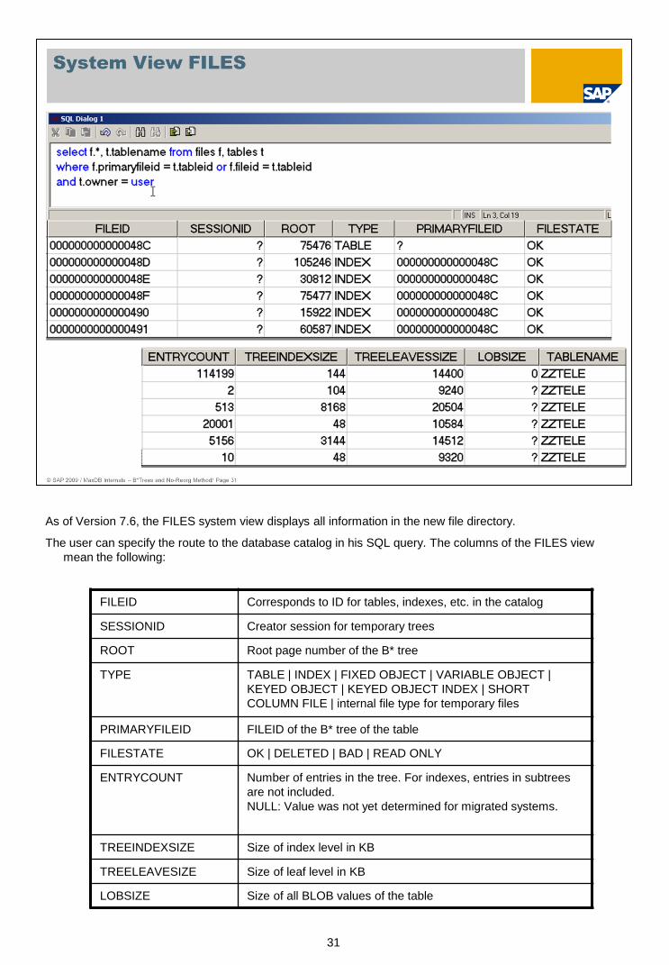
As of Version 7.6, the FILES system view displays all information in the new file directory.
The user can specify the route to the database catalog in his SQL query. The columns of the FILES view
mean the following:
FILEID Corresponds to ID for tables, indexes, etc. in the catalog
SESSIONID Creator session for temporary trees
ROOT Root page number of the B* tree
TYPE TABLE | INDEX | FIXED OBJECT | VARIABLE OBJECT |
KEYED OBJECT | KEYED OBJECT INDEX | SHORT
COLUMN FILE | internal file type for temporary files
PRIMARYFILEID FILEID of the B* tree of the table
FILESTATE OK | DELETED | BAD | READ ONLY
ENTRYCOUNT Number of entries in the tree. For indexes, entries in subtrees
are not included.
NULL: Value was not yet determined for migrated systems.
TREEINDEXSIZE Size of index level in KB
TREELEAVESIZE Size of leaf level in KB
LOBSIZE Size of all BLOB values of the table
32
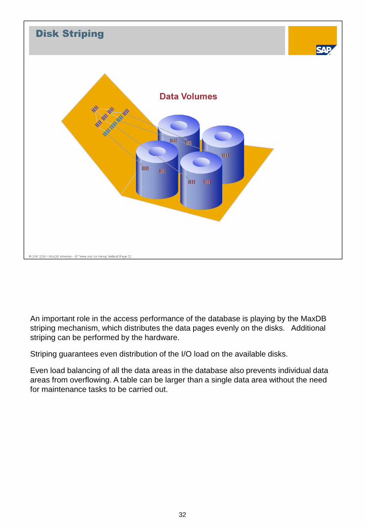
An important role in the access performance of the database is playing by the MaxDB
striping mechanism, which distributes the data pages evenly on the disks. Additional
striping can be performed by the hardware.
Striping guarantees even distribution of the I/O load on the available disks.
Even load balancing of all the data areas in the database also prevents individual data
areas from overflowing. A table can be larger than a single data area without the need
for maintenance tasks to be carried out.

33
The I/O concept of the database works according to the shadow storage administration principle. The core
elements are: optimized support of symmetrical multi-processor systems; the transfer of as many I/Os as
possible to asynchronous execution; and highly-optimized data backup performance suited to the dimensions
of modern databases.
A user task should not be forced to wait for I/O processes to come to an end. All change operations are
executed in the main memory. The I/O subsystem must ensure that the system always retains its ability to
restart at the point of termination.
The shadow storage administration distinguishes between originals and copies. When the system is restarted
after termination, the valid states of the data pages are automatically recognized. The concept is based on
savepoint cycles, which are closed by a savepoint. A completed cycle is specified by the version number of
its savepoint. This number is referred to as the 'savepoint version' or 'converter version'.
The different versions of the data pages that arise as a result of the savepoint cycles are administered in the
converter. Here the originals and copies of the logical data pages are assigned physical blocks. Thus the
location at which a logical data page is stored can change from savepoint cycle to savepoint cycle.
Another structure is employed for the administration of the data volumes (FBM: Free Block Manager). As the
logical data pages no longer have a definite location in the memory, the FBM administers the states of the
physical blocks. These structures enable optimal performance for data backup as well.
The data cache was optimized with regard to SMP support by the use of pager and server tasks that work in
parallel.
34
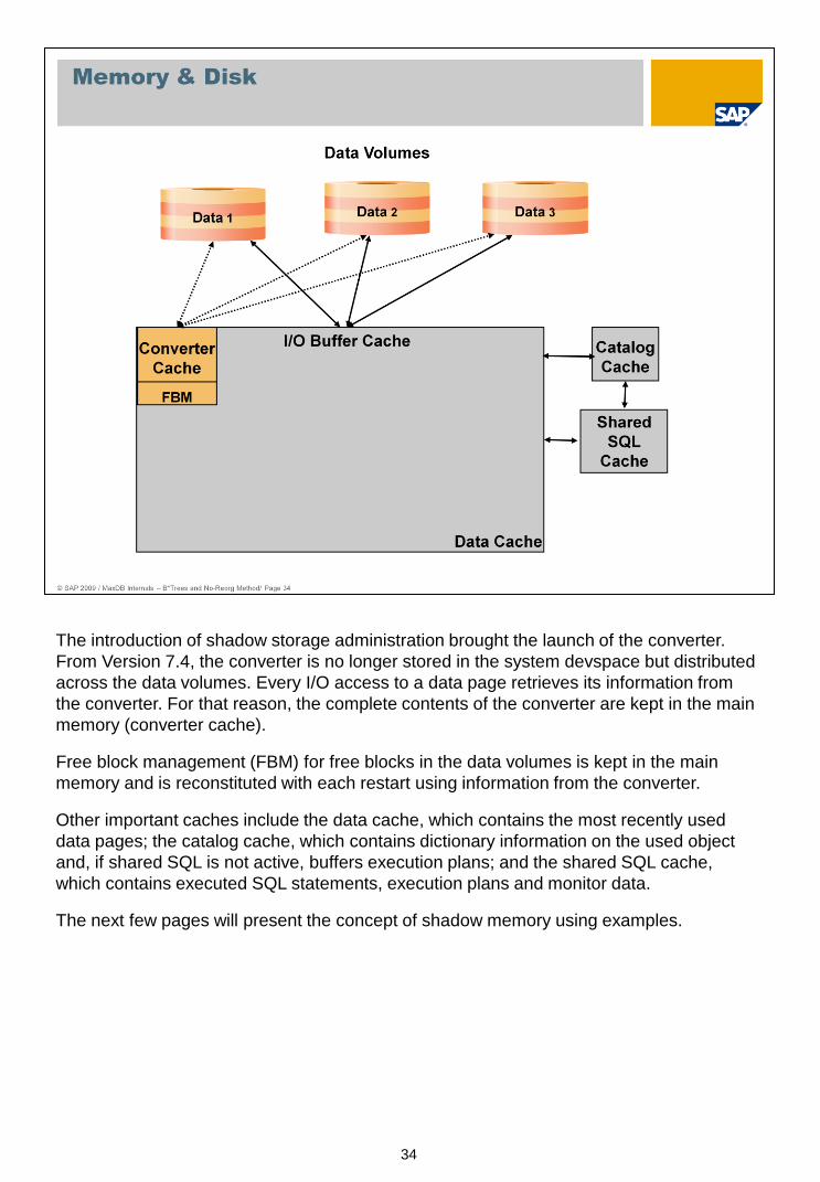
The introduction of shadow storage administration brought the launch of the converter.
From Version 7.4, the converter is no longer stored in the system devspace but distributed
across the data volumes. Every I/O access to a data page retrieves its information from
the converter. For that reason, the complete contents of the converter are kept in the main
memory (converter cache).
Free block management (FBM) for free blocks in the data volumes is kept in the main
memory and is reconstituted with each restart using information from the converter.
Other important caches include the data cache, which contains the most recently used
data pages; the catalog cache, which contains dictionary information on the used object
and, if shared SQL is not active, buffers execution plans; and the shared SQL cache,
which contains executed SQL statements, execution plans and monitor data.
The next few pages will present the concept of shadow memory using examples.
35
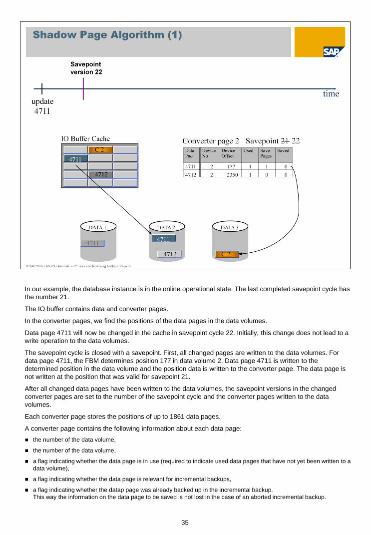
In our example, the database instance is in the online operational state. The last completed savepoint cycle has
the number 21.
The IO buffer contains data and converter pages.
In the converter pages, we find the positions of the data pages in the data volumes.
Data page 4711 will now be changed in the cache in savepoint cycle 22. Initially, this change does not lead to a
write operation to the data volumes.
The savepoint cycle is closed with a savepoint. First, all changed pages are written to the data volumes. For
data page 4711, the FBM determines position 177 in data volume 2. Data page 4711 is written to the
determined position in the data volume and the position data is written to the converter page. The data page is
not written at the position that was valid for savepoint 21.
After all changed data pages have been written to the data volumes, the savepoint versions in the changed
converter pages are set to the number of the savepoint cycle and the converter pages written to the data
volumes.
Each converter page stores the positions of up to 1861 data pages.
A converter page contains the following information about each data page:
the number of the data volume,
the number of the data volume,
a flag indicating whether the data page is in use (required to indicate used data pages that have not yet been written to a
data volume),
a flag indicating whether the data page is relevant for incremental backups,
a flag indicating whether the datap page was already backed up in the incremental backup.
This way the information on the data page to be saved is not lost in the case of an aborted incremental backup.
36
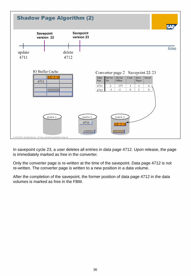
In savepoint cycle 23, a user deletes all entries in data page 4712. Upon release, the page
is immediately marked as free in the converter.
Only the converter page is re-written at the time of the savepoint. Data page 4712 is not
re-written. The converter page is written to a new position in a data volume.
After the completion of the savepoint, the former position of data page 4712 in the data
volumes is marked as free in the FBM.

37
In savepoint 24, the database uses page 4712 for new data. The data page could already
have been reassigned in savepoint cycle 23.
The new data page is marked as used in the converter. But no position for a data volume has
been entered yet.
Initially, changes take place only in the cache. Upon completion of the savepoint cycle, the
data page is written and its position entered in the converter. The converter page is written
to a new position in a data volume.
38
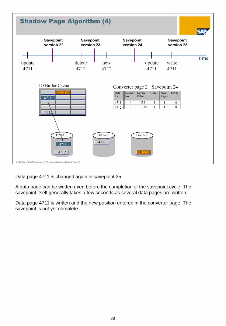
Data page 4711 is changed again in savepoint 25.
A data page can be written even before the completion of the savepoint cycle. The
savepoint itself generally takes a few seconds as several data pages are written.
Data page 4711 is written and the new position entered in the converter page. The
savepoint is not yet complete.
39
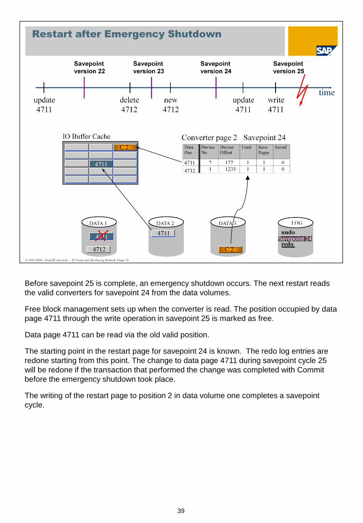
Before savepoint 25 is complete, an emergency shutdown occurs. The next restart reads
the valid converters for savepoint 24 from the data volumes.
Free block management sets up when the converter is read. The position occupied by data
page 4711 through the write operation in savepoint 25 is marked as free.
Data page 4711 can be read via the old valid position.
The starting point in the restart page for savepoint 24 is known. The redo log entries are
redone starting from this point. The change to data page 4711 during savepoint cycle 25
will be redone if the transaction that performed the change was completed with Commit
before the emergency shutdown took place.
The writing of the restart page to position 2 in data volume one completes a savepoint
cycle.
40
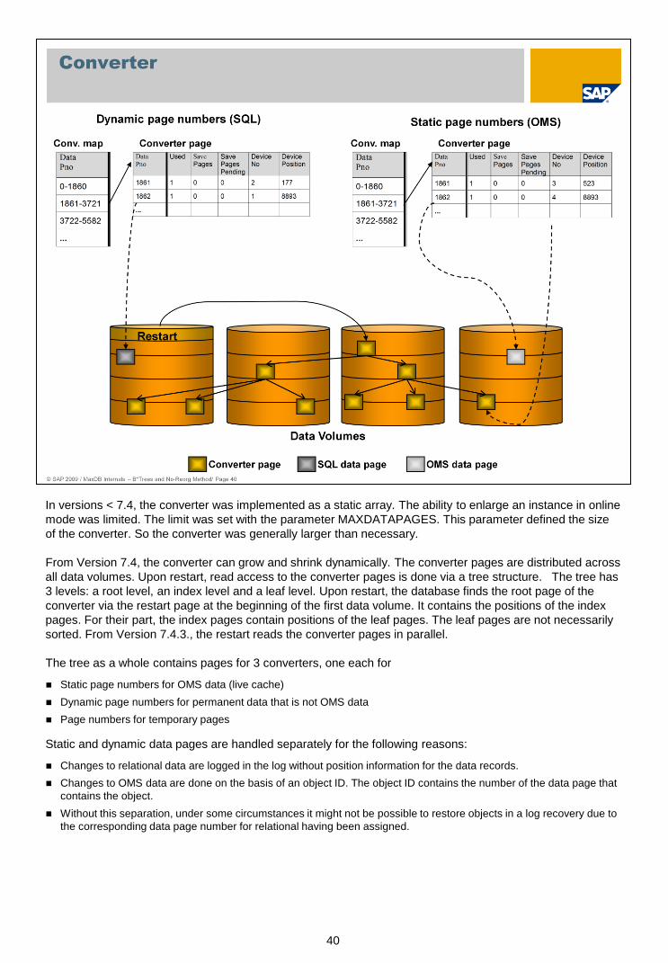
In versions < 7.4, the converter was implemented as a static array. The ability to enlarge an instance in online
mode was limited. The limit was set with the parameter MAXDATAPAGES. This parameter defined the size
of the converter. So the converter was generally larger than necessary.
From Version 7.4, the converter can grow and shrink dynamically. The converter pages are distributed across
all data volumes. Upon restart, read access to the converter pages is done via a tree structure. The tree has
3 levels: a root level, an index level and a leaf level. Upon restart, the database finds the root page of the
converter via the restart page at the beginning of the first data volume. It contains the positions of the index
pages. For their part, the index pages contain positions of the leaf pages. The leaf pages are not necessarily
sorted. From Version 7.4.3., the restart reads the converter pages in parallel.
The tree as a whole contains pages for 3 converters, one each for
Static page numbers for OMS data (live cache)
Dynamic page numbers for permanent data that is not OMS data
Page numbers for temporary pages
Static and dynamic data pages are handled separately for the following reasons:
Changes to relational data are logged in the log without position information for the data records.
Changes to OMS data are done on the basis of an object ID. The object ID contains the number of the data page that
contains the object.
Without this separation, under some circumstances it might not be possible to restore objects in a log recovery due to
the corresponding data page number for relational having been assigned.
41
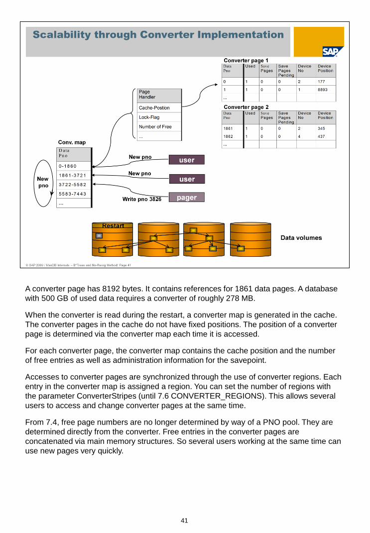
A converter page has 8192 bytes. It contains references for 1861 data pages. A database
with 500 GB of used data requires a converter of roughly 278 MB.
When the converter is read during the restart, a converter map is generated in the cache.
The converter pages in the cache do not have fixed positions. The position of a converter
page is determined via the converter map each time it is accessed.
For each converter page, the converter map contains the cache position and the number
of free entries as well as administration information for the savepoint.
Accesses to converter pages are synchronized through the use of converter regions. Each
entry in the converter map is assigned a region. You can set the number of regions with
the parameter ConverterStripes (until 7.6 CONVERTER_REGIONS). This allows several
users to access and change converter pages at the same time.
From 7.4, free page numbers are no longer determined by way of a PNO pool. They are
determined directly from the converter. Free entries in the converter pages are
concatenated via main memory structures. So several users working at the same time can
use new pages very quickly.
42
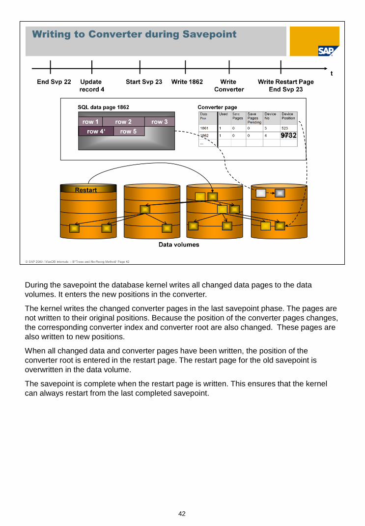
During the savepoint the database kernel writes all changed data pages to the data
volumes. It enters the new positions in the converter.
The kernel writes the changed converter pages in the last savepoint phase. The pages are
not written to their original positions. Because the position of the converter pages changes,
the corresponding converter index and converter root are also changed. These pages are
also written to new positions.
When all changed data and converter pages have been written, the position of the
converter root is entered in the restart page. The restart page for the old savepoint is
overwritten in the data volume.
The savepoint is complete when the restart page is written. This ensures that the kernel
can always restart from the last completed savepoint.

43
The Free Block Manager, which only exists in the memory, administers all data devices
using a bit list for each device. This includes the used capacity status and the backup
status. The possible statuses are:
Free:
The block is free and can be allocated.
Occupied:
The block is occupied.
Free after savepoint:
The block can be released after the current savepoint has been successfully completed.
Backup:
The block belongs to a backup that is in process. When the block has been backed up, that is,
written to the backup medium, the status is reset.
If a block has been selected for a backup in process, the used capacity status of a block
can change. A block can only be reallocated when the used capacity and backup
statuses are both "free."
From version 7.4, the Free Block Manager is part of converter management.

44
The savepoint is a core function of the I/O concept. The illustration shows what happens during a savepoint.
The savepoint writes the data from the data cache and the converter cache to the corresponding data
volumes. Due to the size of the two caches, this cannot be carried out as a synchronous action; the system
would be blocked for too long. There has to be a short phase in which the caches can be securely flushed,
but this must be kept to a minimum.
The standard is for savepoints to occur at intervals of 10 minutes. To minimize the amount of data to be
flushed in the protected section (marked red), the savepoint begins by flushing the data cache parallel to
operation. The data cache is processed by several pagers simultaneously. The largest share of pages is
flushed in this phase.
In the second phase, a flag is set which prohibits clearing operations on B* trees. It is also prohibited to open
new transactions during this phase. All pages that were changed in the course of the first phase are marked
as savepoint relevant. An open trans file is created for open transactions.
In the last phase, all pages that were marked during the second phase are flushed. The flags are reset. First,
all changed pages are written to the data volumes. The savepoint is complete when the restart page is
written. Afterwards the savepoint version (number) is updated.
The protected phase of the savepoint is generally quite short and goes unnoticed by the end user.
45
Data backups are carried out with a block size of 8 x 8 KB and can be parallelized.
Data backups start with a savepoint. A backup includes the data existing at the time of the
savepoint. Subsequent changes are not included in the backup. The database can write
further savepoints while the backup is in process.
46
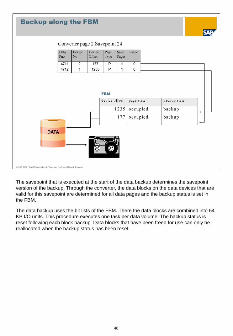
The savepoint that is executed at the start of the data backup determines the savepoint
version of the backup. Through the converter, the data blocks on the data devices that are
valid for this savepoint are determined for all data pages and the backup status is set in
the FBM.
The data backup uses the bit lists of the FBM. There the data blocks are combined into 64
KB I/O units. This procedure executes one task per data volume. The backup status is
reset following each block backup. Data blocks that have been freed for use can only be
reallocated when the backup status has been reset.

47
This illustration depicts a data transfer from the data volumes to the backup media. Each
volume has a task that puts the 64 KB units into a buffer. One task per backup device
reads the blocks from the buffer and stores them on the backup medium.
The limits of this process are posed either by the access speed of the data volumes, the
writing performance of the backup devices or the transport layer (e.g. network) between
the database server and the backup devices. As long as these limits are not reached, the
process scales with any other backup device in parallel operation.

48
Server tasks or pager tasks have a reduced stack requirement as they do not have to carry
out syntax analysis or related activities, but only process pre-translated requests.
To prevent the server tasks from negatively influencing the user tasks due to their high
throughput, they are created in their own thread (UKT) in the standard.
During times in which a system is working with a moderate to low I/O load, pager tasks
perform so-called write-ahead operations. This means that data pages that have been
changed in the data cache are written to the data volumes ahead of time, i.e. before a
savepoint or displacement. This in turn means a reduction of the burden on the first phase
of the coming savepoint as there is substantially less I/O to be handled. In general, a
favorable setting of the pager tasks can ensure a consistently low and largely
asynchronous I/O load.
49
The data cache was divided into segments to enable better SMP support and to accelerate
savepoints. Each segment is secured by its own region. The data pages are uniquely
assigned to a segment, that is, a data page with the page number 4711 (pno), for example,
is always administered in the second cache segment.
As of version 7.6.03 the number of possible segments has increased from 64 to 1024.

50
From version 7.5, you can freeze the data area of a database instance using a snapshot.
In versions 7.5 and 7.6 a snapshot is generated in the ADMIN state. As of 7.7 it is also
possible to create it in ONLINE mode. Later you can reset the data to its state at the time
of the snapshot and/or delete the snapshot.
With the CREATE_SNAPSHOT command, the database kernel copies the restart page
from the second block of the first data volume to another position. The complete converter
is also copied. The original restart record contains a reference to the restart record that
corresponds to the snapshot.
With the command RESTORE_SNAPSHOT, the current converter is deleted. All blocks
that are no longer needed are marked as free in the FBM. The log is formatted such that
the state HISTLOST occurs. At the next restart, the instance works with the data as they
were at the time of the CREATE_SNAPSHOT.
The statement DROP_SNAPSHOT deletes the restart record and the corresponding
converter that is relevant for the snapshot. The FBM marks all blocks that are no longer
needed as free.
Up to 7.6 MaxDB supports only a single snapshot, as of 7.7 several snapshots can be
generated. Operating the instance with one or several snapshot(s) uses more of the
capacity of the data area.
51
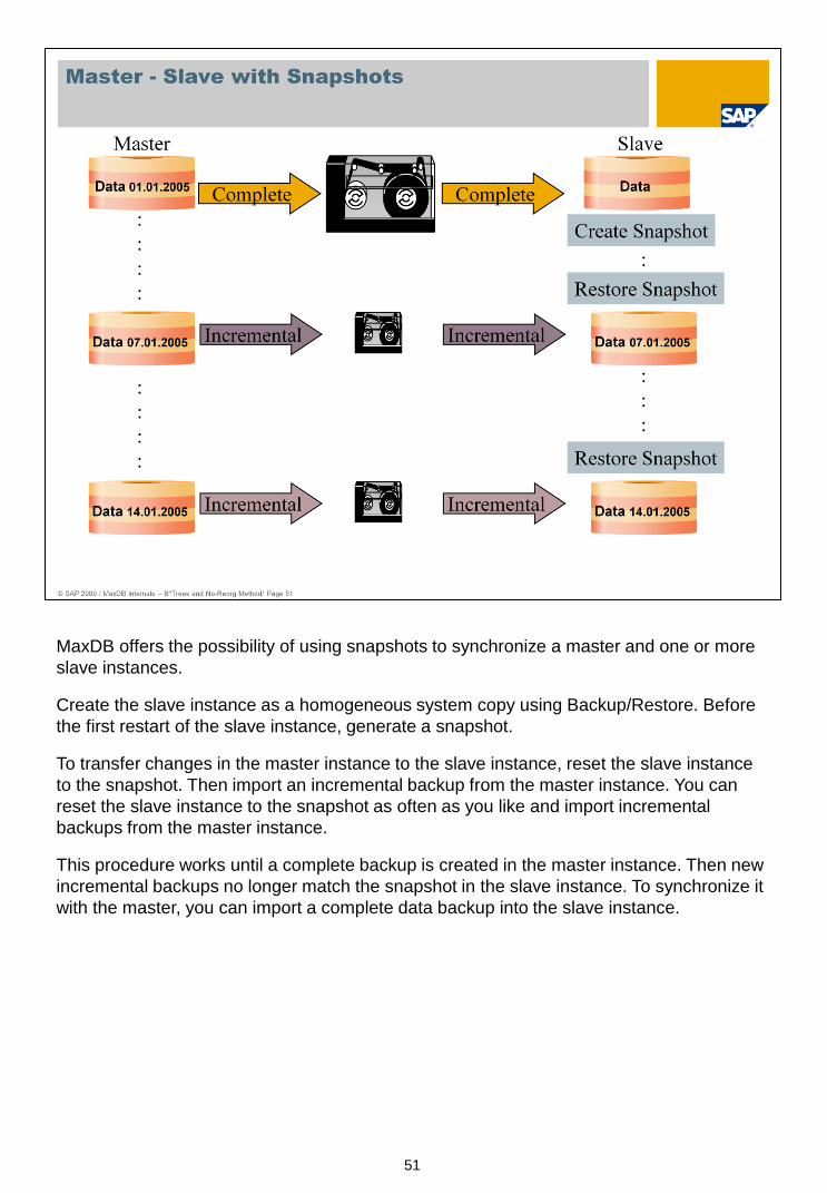
MaxDB offers the possibility of using snapshots to synchronize a master and one or more
slave instances.
Create the slave instance as a homogeneous system copy using Backup/Restore. Before
the first restart of the slave instance, generate a snapshot.
To transfer changes in the master instance to the slave instance, reset the slave instance
to the snapshot. Then import an incremental backup from the master instance. You can
reset the slave instance to the snapshot as often as you like and import incremental
backups from the master instance.
This procedure works until a complete backup is created in the master instance. Then new
incremental backups no longer match the snapshot in the slave instance. To synchronize it
with the master, you can import a complete data backup into the slave instance.
52
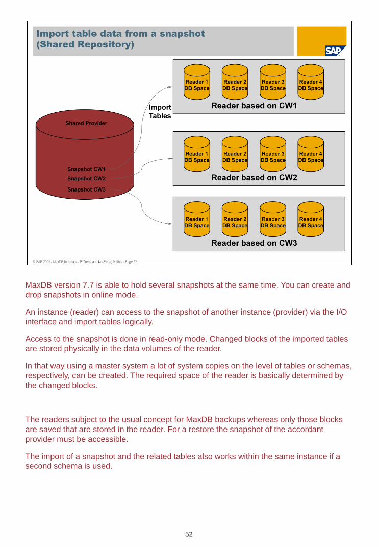
MaxDB version 7.7 is able to hold several snapshots at the same time. You can create and
drop snapshots in online mode.
An instance (reader) can access to the snapshot of another instance (provider) via the I/O
interface and import tables logically.
Access to the snapshot is done in read-only mode. Changed blocks of the imported tables
are stored physically in the data volumes of the reader.
In that way using a master system a lot of system copies on the level of tables or schemas,
respectively, can be created. The required space of the reader is basically determined by
the changed blocks.
The readers subject to the usual concept for MaxDB backups whereas only those blocks
are saved that are stored in the reader. For a restore the snapshot of the accordant
provider must be accessible.
The import of a snapshot and the related tables also works within the same instance if a
second schema is used.

53