Embed Size (px)
Citation preview

58332 Schwelm/Germany · Max-Klein-Str. 2 a · Tel. (+49) 23 36-9143 83 · Fax (+49) 23 36-8 37 75 · www.th-broer.de
THORSTEN BROERRÜST- UND SCHMIEDETECHNIK
FEUERBACHERSPANNKEILE DBGM
1.0 Versions, Spare Parts Lists and Application Areas
Instructions for Feuerbacher Tensioning Keys
1.1 Feuerbacher Tensioning Key version ”SB”1.1.1 Data sheet version ”SB”
1.2 Feuerbacher Tensioning Key version ”D”1.2.1 Data sheet version ”D”
1.3 Feuerbacher Tensioning Key version ”TD”1.4 Feuerbacher Tensioning Key version ”Standard”
2.0 Mounting and Dismounting of Tensioning Keys 2.1 Mounting of Tensioning Keys 2.2 Dismounting of Tensioning Keys 2.3 Tightening Torques
3.0 Service and Maintenance3.1 General Service 3.2 Tensioning Screw Mounting/Dismounting/Service3.3 Mounting and Servicing of the Nut and of the Retaining Ring 3.4 Dismounting the Nut and the Retaining Ring3.5 Cup Springs 3.6 Mounting of Taper Pins3.7 Disassembling of the Tensioning Keys
4.0 General4.1 Hammer and Die Slants
Angles at Tension Side of Die, Hammer or Press4.2 Guiding valves size of tensioning wedges / weight forging-die4.3 Installation variants4.4 Taps / Threading Die4.5 Tools / Auxiliary Materials4.6 Customs Number or Commodity Codes for Feuerbacher Tensioning Keys
and Spare Parts4.7 Utility Patents and Trademarks

58332 Schwelm/Germany · Max-Klein-Str. 2 a · Tel. (+49) 23 36-9143 83 · Fax (+49) 23 36-8 37 75 · www.th-broer.de
THORSTEN BROERRÜST- UND SCHMIEDETECHNIK
FEUERBACHERSPANNKEILE DBGM
2411011 3
cross section nut
All rights reserved.No part of this publication may be reproduced, photocopied,stored in a retrieval system or transmitted without the priorwritten permission of the author.
1 = tensioning screw 2 = nut 3 = taper pin 4 = retaining ring10 = cup springs11 = spacing ring
Application area:
The version ”SB” of our Feuerbacher tensioningkeys is provided with a positive pitch, a tensio-ning screw effective at cross-section, and outercup springs.
Tensioning keys of the version ”SB” are particu-larly suited for modern drop forging hammers.
1.0
Versions, Spare Parts Listsand Application Areas
1.1 Feuerbacher Tensioning Key ”SB Version”

58332 Schwelm/Germany · Max-Klein-Str. 2 a · Tel. (+49) 23 36-9143 83 · Fax (+49) 23 36-8 37 75 · www.th-broer.de
THORSTEN BROERRÜST- UND SCHMIEDETECHNIK
FEUERBACHERSPANNKEILE DBGM
All rights reserved.No part of this publication may be reproduced, photocopied,stored in a retrieval system or transmitted without the priorwritten permission of the author.
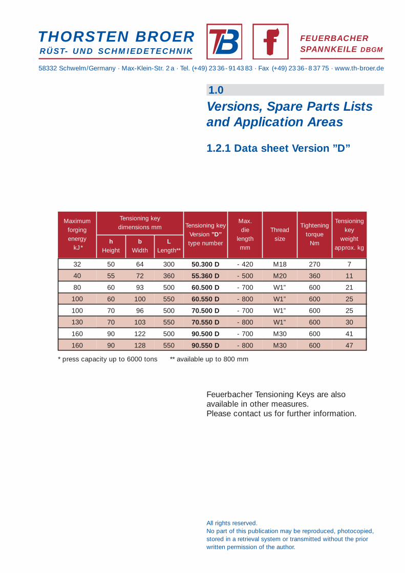
Feuerbacher Tensioning Keys are alsoavailable in other measures.Please contact us for further information.
1.0
Versions, Spare Parts Listsand Application Areas
1.1.1 Data sheet Version ”SB”
>160
>160
>160
>160
100 60 95 600 60.600 SB - 800 M27 570-600 25
32
Tensioning keydimensions mm
Maximumforgingenergy
kJ
32 50 64 300 50.300 SB - 420 M20 360-380 7
40 55 72 360 55.360 SB - 500 M24 530-560 11
40 55 93 500 55.500 SB - 650 M24 530-560 18
80 60 93 500 60.500 SB - 700 M27 570-600 20
50 72 400
400
50.400 SB - 520 M20 360-380 11
hHeight
bWidth
LLength
Tensioning keyVersion ”SB”type number
Max.die
lengthmm
Threadsize
Tighteningtorque
Nm
Tensioningkey
weightapprox. kg
40 55 72 55.400 SB - 520 M22 450-480 12
40080 60 85 60.400 SB - 520 M22 450-480 15
550100 60 94 60.550 SB - 750 M27 570-600 23
700100 60 96 60.700 SB - 900 M27 570-600 30
130 70 96 500 70.500 SB - 700 M27 570-600 24
550130 70 100 70.550 SB - 750 M27 570-600 30
130 70 104 600 70.600 SB - 800 M27 570-600 30
700130 70 112 70.700 SB - 900 M27 570-600 34
130 70 120 800 70.800 SB - 1000 M27 570-600 52
600>160 80 102 80.600 SB - 850 M30 600 36
>160 80 112 700 80.700 SB - 900 M30 600 39
80080 122 80.800 SB - 1000 M30 600 60
90 122 500 90.500 SB - 750 M30 600 40
60090 126 90.600 SB - 900 M30 600 50
90 128 700 90.700 SB - 1000 M30 600 60
80090 128 90.800 SB - 1100 M30 600 67
>160

58332 Schwelm/Germany · Max-Klein-Str. 2 a · Tel. (+49) 23 36-9143 83 · Fax (+49) 23 36-8 37 75 · www.th-broer.de
THORSTEN BROERRÜST- UND SCHMIEDETECHNIK
FEUERBACHERSPANNKEILE DBGM
8 6 5 7 4 23 1
cross section nut
All rights reserved.No part of this publication may be reproduced, photocopied,stored in a retrieval system or transmitted without the priorwritten permission of the author.
1 = tensioning screw2 = nut3 = taper pin4 = retaining ring5 = cup washers6 = spherical face washe7 = guide bush8 = damper
Application area:
With the Feuerbacher tensioning keyversion ”D” the displacement tendencies ofthe tensioning key halves absorb each otherby means of a damper (block). This appliesto application at the upper die, in particular.
Due to the inner cup springs this tensioningkey version is particularly suited for presses.
1.0
Versions, Spare Parts Listsand Application Areas
1.2 Feuerbacher Tensioning Key Version ”D”
58332 Schwelm/Germany · Max-Klein-Str. 2 a · Tel. (+49) 23 36-9143 83 · Fax (+49) 23 36-8 37 75 · www.th-broer.de
THORSTEN BROERRÜST- UND SCHMIEDETECHNIK
FEUERBACHERSPANNKEILE DBGM
All rights reserved.No part of this publication may be reproduced, photocopied,stored in a retrieval system or transmitted without the priorwritten permission of the author.
Feuerbacher Tensioning Keys are alsoavailable in other measures.Please contact us for further information.
1.0
Versions, Spare Parts Listsand Application Areas
1.2.1 Data sheet Version ”D”
40
Tensioning keydimensions mm
Maximumforgingenergy
kJ*
* press capacity up to 6000 tons ** available up to 800 mm
32 50 64 300 50.300 D - 420 M18 270 7
80 60 93 500 60.500 D - 700 W1” 600 21
100 70 96 500 70.500 D - 700 W1” 600 25
160 90 122 500 90.500 D - 700 M30 600 41
55 72 360
550
55.360 D - 500 M20 360 11
hHeight
bWidth
LLength**
Tensioning keyVersion ”D”type number
Max.die
lengthmm
Threadsize
Tighteningtorque
Nm
Tensioningkey
weightapprox. kg
100 60 100 60.550 D - 800 W1” 600 25
550130 70 103 70.550 D - 800 W1” 600 30
550160 90 128 90.550 D - 800 M30 600 47

58332 Schwelm/Germany · Max-Klein-Str. 2 a · Tel. (+49) 23 36-9143 83 · Fax (+49) 23 36-8 37 75 · www.th-broer.de
THORSTEN BROERRÜST- UND SCHMIEDETECHNIK
FEUERBACHERSPANNKEILE DBGM
243 11011 9
screw head nut
All rights reserved.No part of this publication may be reproduced, photocopied,stored in a retrieval system or transmitted without the priorwritten permission of the author.
1 = screw 2 = nut 3 = taper pin 4 = retaining ring 9 = Damper plates10 = cup-springs11 = distance ring
Application area:
The version ”TD” of our Feuerbacher tensioningkeys is provided with a concave/convex pitch,an inner damper system and outer cup springs.
Tensioning keys of the version ”TD” are nolonger supplied for new plants.
1.0
Versions, Spare Parts Listsand Application Areas
1.3 Feuerbacher Tensioning Key Version ”TD”

58332 Schwelm/Germany · Max-Klein-Str. 2 a · Tel. (+49) 23 36-9143 83 · Fax (+49) 23 36-8 37 75 · www.th-broer.de
THORSTEN BROERRÜST- UND SCHMIEDETECHNIK
FEUERBACHERSPANNKEILE DBGM
6 53 1 24
screw head nut
All rights reserved.No part of this publication may be reproduced, photocopied,stored in a retrieval system or transmitted without the priorwritten permission of the author.
1 = screw2 = nut3 = taper pin4 = retaining ring5 = cup-springs6 = spherical disk
Application area:
The ”Standard-Version” of our Feuerbachertensioning keys is provided with aconcave/convex pitch and inner cup springs.
Feuerbacher tensioning keys of the ”Standard-Version” will only be applied within plants thathave been working with this tensioning keyversion for years.
1.0
Versions, Spare Parts Listsand Application Areas
1.4 Feuerbacher Tensioning Key ”Standard-Version”

2.0
Mounting and Dismountingof Tensioning Keys
58332 Schwelm/Germany · Max-Klein-Str. 2 a · Tel. (+49) 23 36-9143 83 · Fax (+49) 23 36-8 37 75 · www.th-broer.de
2.1 Mounting- side 1 -
THORSTEN BROERRÜST- UND SCHMIEDETECHNIK
FEUERBACHERSPANNKEILE DBGM
max. 15 up to 20 mm
All rights reserved.No part of this publication may be reproduced, photocopied,stored in a retrieval system or transmitted without the priorwritten permission of the author.
Prior to mounting, the thread of the screw isto be cleaned/blown completely dry withcompressed air.
The tensioning key halves should be turnedback by approx. 15 - 20 mm.
Mounting should be carried out by 2 men.
Mounting the tensioning key into the machine.At the upper die, the tensioning key should bepressed to the bottom of the ram by means ofwedges.
notice:1 mm insert results in approx 10 mmchange in the length of the traverse
shimsof differingthickness
key orinsert
tensioning key before mounting

58332 Schwelm/Germany · Max-Klein-Str. 2 a · Tel. (+49) 23 36-9143 83 · Fax (+49) 23 36-8 37 75 · www.th-broer.de
THORSTEN BROERRÜST- UND SCHMIEDETECHNIK
FEUERBACHERSPANNKEILE DBGM
max. -10 up to -15 mm max. +10 up to +15 mm
0position
All rights reserved.No part of this publication may be reproduced, photocopied,stored in a retrieval system or transmitted without the priorwritten permission of the author.
One man takes charge of controlling thehammer, the other one takes charge oftightening the nut. The use of a clutched orelectric screw driver is by all means possiblebut the necessary torque will have to becontrolled by a torque spanner. Cf. details inthe table of dimensions.
2.0
Mounting and Dismountingof Tensioning Keys
2.1 Mounting- side 2 -
tensioning key after mounting
After some initial setting hits, the nut canusually still be tightened further.
The sequence of setting hits and tighteningis now to be repeated several times (8 - 10repeats) until the nut can no longer betightened further.
During forging the tightening torque must becontrolled regularly.

58332 Schwelm/Germany · Max-Klein-Str. 2 a · Tel. (+49) 23 36-9143 83 · Fax (+49) 23 36-8 37 75 · www.th-broer.de
THORSTEN BROERRÜST- UND SCHMIEDETECHNIK
FEUERBACHERSPANNKEILE DBGM
All rights reserved.No part of this publication may be reproduced, photocopied,stored in a retrieval system or transmitted without the priorwritten permission of the author.
Prior to dismounting, the thread of the screw isto be cleaned/blown completely dry with com-pressed air.
Dismounting should be carried out by two men.One man takes charge of controlling the ham-mer, the other one takes charge of unscrewingthe nut with a ratchet.
The use of a clutched or electric screw driver isnot advisable, as this will load the tighteningsystem or the taper pin excessively. Do not tryin any way to dismount the tensioning keyby unscrewing the nut by force. This willdamage the thread and taper pin.
After some initial setting hits, the nut canusually not yet be turned more than a tinyfraction of its perimeter (approx. 30°).
The sequence of setting hits and unscrewingwill have to be repeated several times (8 -15repeats) until the nut can be turned a larger bitwithout using much force.
After that turn the nut back until the thread isexposed as much as possible. Then clean thethread with compressed air from the scalesand check for damages.
2.0
Mounting and Dismountingof Tensioning Keys
2.2 Dismounting
max. 30°
release max. 30°and then hammercontinuously
repeatseveral timesuntil screwnot can beturnedeasy !
attention: always loosenthe lower tensioning key first !
58332 Schwelm/Germany · Max-Klein-Str. 2 a · Tel. (+49) 23 36-9143 83 · Fax (+49) 23 36-8 37 75 · www.th-broer.de
THORSTEN BROERRÜST- UND SCHMIEDETECHNIK
FEUERBACHERSPANNKEILE DBGM
All rights reserved.No part of this publication may be reproduced, photocopied,stored in a retrieval system or transmitted without the priorwritten permission of the author.
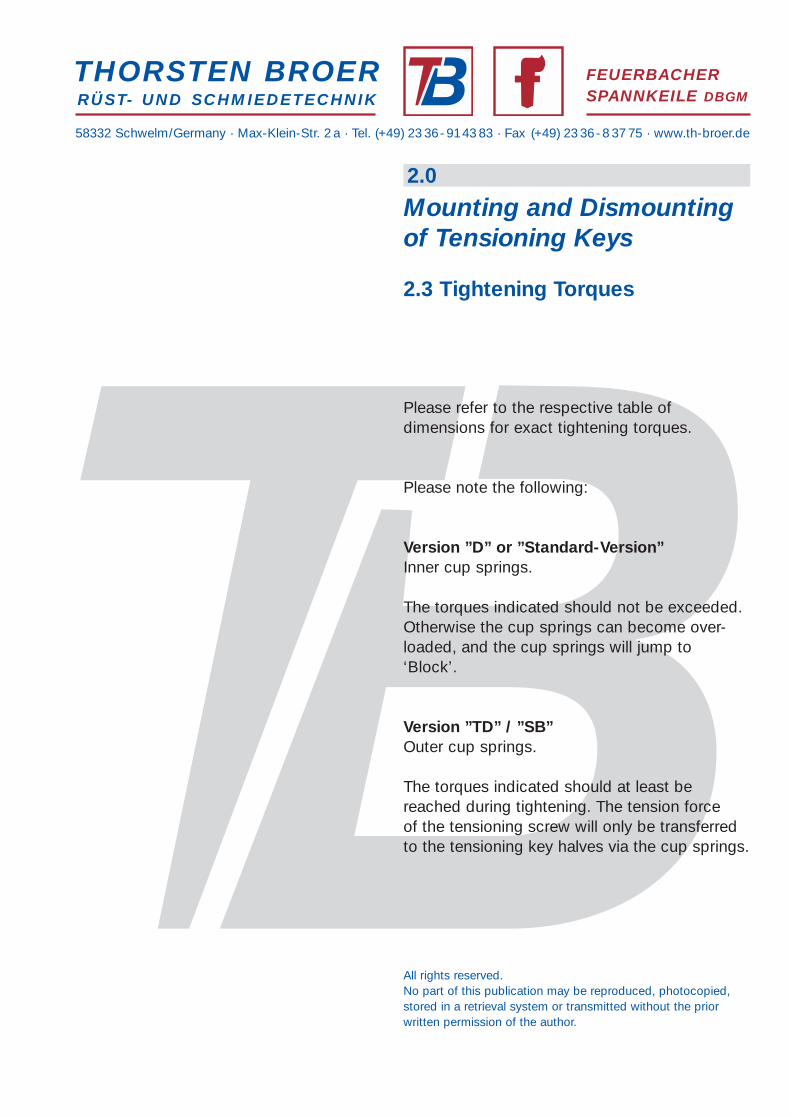
Please refer to the respective table ofdimensions for exact tightening torques.
Please note the following:
Version ”D” or ”Standard-Version”Inner cup springs.
The torques indicated should not be exceeded.Otherwise the cup springs can become over-loaded, and the cup springs will jump to‘Block’.
Version ”TD” / ”SB”Outer cup springs.
The torques indicated should at least bereached during tightening. The tension forceof the tensioning screw will only be transferredto the tensioning key halves via the cup springs.
2.0
Mounting and Dismountingof Tensioning Keys
2.3 Tightening Torques

58332 Schwelm/Germany · Max-Klein-Str. 2 a · Tel. (+49) 23 36-9143 83 · Fax (+49) 23 36-8 37 75 · www.th-broer.de
THORSTEN BROERRÜST- UND SCHMIEDETECHNIK
FEUERBACHERSPANNKEILE DBGM
All rights reserved.No part of this publication may be reproduced, photocopied,stored in a retrieval system or transmitted without the priorwritten permission of the author.
Feuerbacher tensioning keys are wearable parts. The lifetime of the tensioning key halves and of thecomponent parts will largely dependon service and maintenance.
Scoring on the SurfacesScores and notches on the outer orinner surfaces are process-related.This is confirmed by the latest researchaccording to the finite element method.Nitration or hard facing of the surfaceswill remove the problem in the shortterm only.
Intervals for ServicingFor application in two-shift operationswe recommend exchanging thetensioning keys for servicing / visualinspection within the setup scheduletogether with the dies.
3-4 weeks’ intervals are sufficientbetween general servicing.
A serial number is engraved on the faceof the key halves to enable retracing themanufacturing sequence in accordancewith ISO 9000. Such labelling is notsuited for the avoidance of mix-ups,and we therefore recommend providingthe tensioning keys with clear markingson the top side.
Service Procedure Disassembling of the tensioning key into itstwo halves.
Baked-on spray residues and slight protu-berances at the scores and notches are onlysanded by means of a grinding stone (fine,approx. 30 mm), a rubber abrasive roll or aswinging sander. Do not in any way grind outthe notches or scores completely. Grinding outwill change the geometry of the tensioning keyand can impair the functioning of the entiretensioning key.
Visual inspection of all components of thetensioning key with regard to apparent wear.The thread in the nut can be improved/sandedwith a tap.
Sand the thread in the tensioning screw with asteel brush or thread file. The thread must notbe reworked with a die corresponding to DIN,as a higher inner diameter will be applied at thegroove of the thread. The respective root radiican be taken from a separate listing of threadsizes. Mind the correct layering of the cupsprings during assembly.
The threads and inner surfaces of the tensioningkeys should be lubricated with plenty of graphi-te grease or copper pastes, prior to assembly.
3.0
Service andMaintenance
3.1 General Service

58332 Schwelm/Germany · Max-Klein-Str. 2 a · Tel. (+49) 23 36-9143 83 · Fax (+49) 23 36-8 37 75 · www.th-broer.de
THORSTEN BROERRÜST- UND SCHMIEDETECHNIK
FEUERBACHERSPANNKEILE DBGM
All rights reserved.No part of this publication may be reproduced, photocopied,stored in a retrieval system or transmitted without the priorwritten permission of the author.
Dismounting
The tensioning key must be disassembled intoits two halves to enable the tensioning screw tobe removed.
Then knock out the taper pin and pull out thetensioning screw from the key half.
Improving the Thread
Sand the thread in the tensioning screw with asteel brush or thread file.
The thread must not be improved with a diecorresponding to DIN, as a higher innerdiameter will be applied at the groove of the thread. The respective root radii can be takenfrom a separate listing of thread sizes.
3.0
Service andMaintenance
3.2 Tensioning ScrewMounting/Dismounting/Service

58332 Schwelm/Germany · Max-Klein-Str. 2 a · Tel. (+49) 23 36-9143 83 · Fax (+49) 23 36-8 37 75 · www.th-broer.de
##
#
Mounting
The tools required are a mandrel and a hammer.
To mount the nut and the retaining ring, thetensioning key half must be tightened uprightinto a vice.
The nut is applied before mounting the retainingring.
The retaining ring is driven into the designatedgroove with a metal strip and a hammer.
Servicing of the Nut
First the tensioning key is disassembled into its2 halves.
The nut can remain in the tensioning key half forservicing. That half of the tensioning key whichcarries the nut is tightened upright into a vice.
The nut will then be fixed with a screw wrench,and the thread can be sanded by means of anappropriate tap.
THORSTEN BROERRÜST- UND SCHMIEDETECHNIK
FEUERBACHERSPANNKEILE DBGM
version ”SB” / ”TD”
version ”D”
”Standard-Version”
All rights reserved.No part of this publication may be reproduced, photocopied,stored in a retrieval system or transmitted without the priorwritten permission of the author.
3.0
Service andMaintenance
3.3 Mounting and Servicing of theNut and of the Retaining Ring

58332 Schwelm/Germany · Max-Klein-Str. 2 a · Tel. (+49) 23 36-9143 83 · Fax (+49) 23 36-8 37 75 · www.th-broer.de
The tools required are twoslot screwdrivers.
First the tensioning key is disassembled intoits 2 halves.
To dismount the nut and the retaining ring, thetensioning key half must be tightened uprightinto a vice.
To dismount the retaining ring, the retaining ringmust be turned into starting position (drawing 1).Following that the retaining ring is lifted out ofthe groove by means of a screw driver (drawing1 and 2).
The retaining ring is then moved clockwise witha second screw driver (drawing 3). After approx.half a rotation the ring will jump upwards out ofthe groove and can be removed.
THORSTEN BROERRÜST- UND SCHMIEDETECHNIK
FEUERBACHERSPANNKEILE DBGM
All rights reserved.No part of this publication may be reproduced, photocopied,stored in a retrieval system or transmitted without the priorwritten permission of the author.
3.0
Service andMaintenance
3.4 Dismounting the Nutand the Retaining Ringdrawing 1
drawing 2
drawing 3

58332 Schwelm/Germany · Max-Klein-Str. 2 a · Tel. (+49) 23 36-9143 83 · Fax (+49) 23 36-8 37 75 · www.th-broer.de
The correct mounting (layering) of the cupsprings is to be observed.
The relevant data on the mounting of therespective cup springs can be ordered from usat short notice.
If the mounting of the cup springs is not carriedout correctly, this can lead to restricted functio-ning of the tensioning key. Furthermore, worncup springs can in the medium term lead toheightened wear of the other components aswell.
Wear of the cup springs can be controlled bylayering the cup springs in accordance with thediagram provided. The height of the assemblycan subsequently be measured with a callipergauge. In case of excessive deviations theassembly should be substituted by a new one.
If you wish, we will send you a drawing thatillustrates the mounting and dimensions ofthe cup springs for the tensioning keys usedby you.
Tensioning Keys with Inner Cup Springs(”Standard-Version” and version ”D”).
Tensioning Keys with Outer Cup Springs(Version ”SB” und version ”TD”).
THORSTEN BROERRÜST- UND SCHMIEDETECHNIK
FEUERBACHERSPANNKEILE DBGM
All rights reserved.No part of this publication may be reproduced, photocopied,stored in a retrieval system or transmitted without the priorwritten permission of the author.
version ”SB” and version ”TD”
”Standard-Version” and version ”D”
cup springs
cup springs
3.0
Service andMaintenance
3.5 Cup Springs

58332 Schwelm/Germany · Max-Klein-Str. 2 a · Tel. (+49) 23 36-9143 83 · Fax (+49) 23 36-8 37 75 · www.th-broer.de
#
Ø
#
The taper pin is driven in with a hammer.
The slant 1 : 100 at the taper pins is in linewith the bearing area of the tensioning keys.
The overlaying ends of the taper pins are cutoff and subsequently sanded flush with thesurface.
The tempered taper pins have a diameter Ø of :
10 mm, 13 mm, 16 mm, 18 mm.
THORSTEN BROERRÜST- UND SCHMIEDETECHNIK
FEUERBACHERSPANNKEILE DBGM
version”SB” / ”TD”
hammer or press
Feuerbacher-tensioning key
taper pinwith slant 1:100
version ”D” /”Standard-Version”
All rights reserved.No part of this publication may be reproduced, photocopied,stored in a retrieval system or transmitted without the priorwritten permission of the author.
3.0
Service andMaintenance
3.6 Mounting of Taper Pins
58332 Schwelm/Germany · Max-Klein-Str. 2 a · Tel. (+49) 23 36-9143 83 · Fax (+49) 23 36-8 37 75 · www.th-broer.de
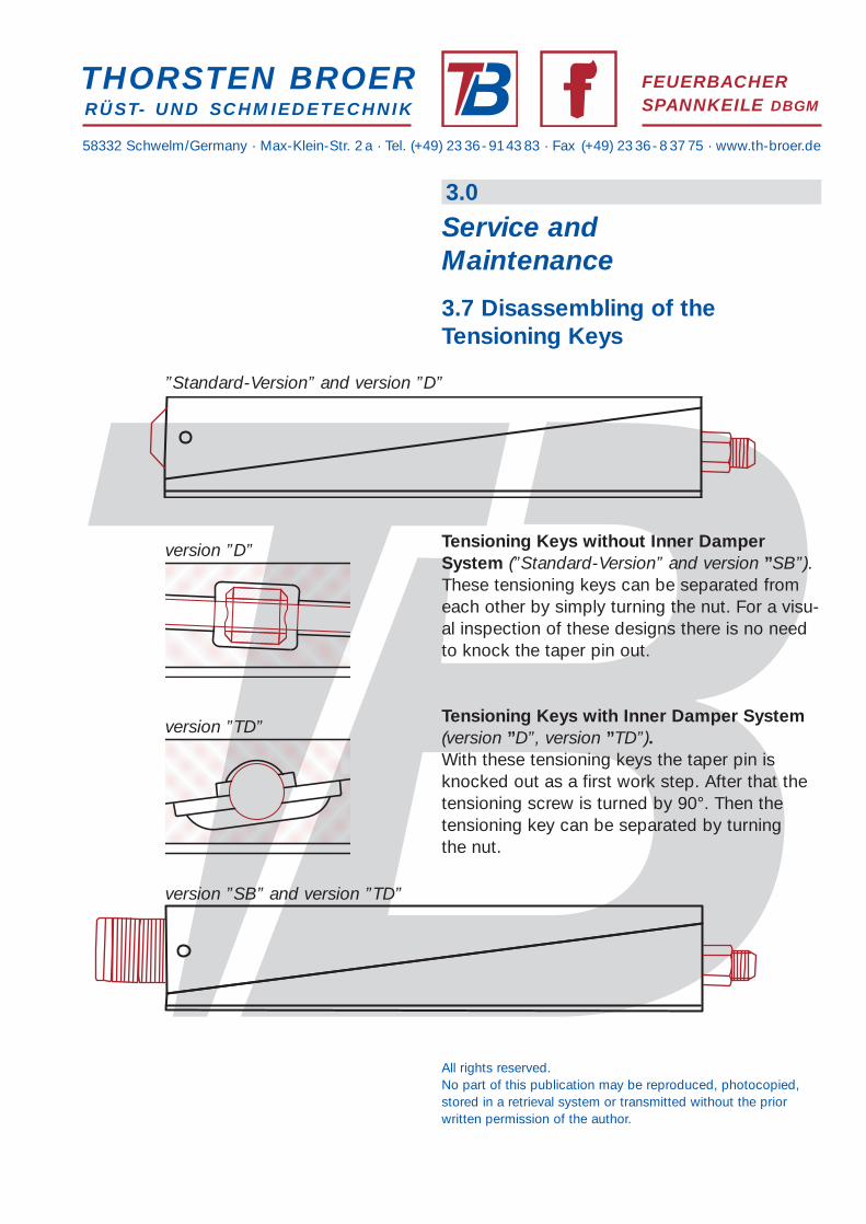
Tensioning Keys without Inner DamperSystem (”Standard-Version” and version ”SB”).These tensioning keys can be separated fromeach other by simply turning the nut. For a visu-al inspection of these designs there is no needto knock the taper pin out.
Tensioning Keys with Inner Damper System(version ”D”, version ”TD”).With these tensioning keys the taper pin isknocked out as a first work step. After that thetensioning screw is turned by 90°. Then thetensioning key can be separated by turningthe nut.
THORSTEN BROERRÜST- UND SCHMIEDETECHNIK
FEUERBACHERSPANNKEILE DBGM
All rights reserved.No part of this publication may be reproduced, photocopied,stored in a retrieval system or transmitted without the priorwritten permission of the author.
3.0
Service andMaintenance
3.7 Disassembling of theTensioning Keys
version ”SB” and version ”TD”
”Standard-Version” and version ”D”
version ”D”
version ”TD”

58332 Schwelm/Germany · Max-Klein-Str. 2 a · Tel. (+49) 23 36-9143 83 · Fax (+49) 23 36-8 37 75 · www.th-broer.de
Dies, Die Holders
Our Feuerbacher tensioning keys have got5° and 15° in standard configuration.
Other configurations are possible if required forspecial applications. The difference betweenhammer press side and slanted die bottomshould not be less than 5° for dies. The lowestpossible slant at the anvil bed side is 8°, and 3°at the die side.
Should there be any work done at the die sidewith a slant of 0°, this will be possible as well.For detailed information on such applicationplease contact us at your earliest convenience.
Smaller Rams, Die Inserts
For smaller rams and for die inserts in die hol-ders, in particular, it is possible to work with a0° slant at the die side. In this case the differen-ce between the two tensioning surfaces shouldnot be below 10°.
THORSTEN BROERRÜST- UND SCHMIEDETECHNIK
FEUERBACHERSPANNKEILE DBGM
All rights reserved.No part of this publication may be reproduced, photocopied,stored in a retrieval system or transmitted without the priorwritten permission of the author.
anvil bed
tensioning keildie
5°15° standard
min.8° 3°
standard
min.
small ramdie insert
holder
tensioning keil
10° - 15° 0°
4.0
General
4.1 Hammer and Die Slants Angles at Tension Side of Die,Hammer or Press

58332 Schwelm/Germany · Max-Klein-Str. 2 a · Tel. (+49) 23 36-9143 83 · Fax (+49) 23 36-8 37 75 · www.th-broer.de
THORSTEN BROERRÜST- UND SCHMIEDETECHNIK
FEUERBACHERSPANNKEILE DBGM
All rights reserved.No part of this publication may be reproduced, photocopied,stored in a retrieval system or transmitted without the priorwritten permission of the author.
90.800
150
300
450
600
750
70.80080.700
80.600
70.600
70.500
60.500
55.400
50.300
500 1000 1500 2000 2500 3000
8°/3° 15°/0° 12°/8° 15°/5°
4.0
General
4.2 Guiding valves size of Tensio-ning Keys / weight forging-diefor version ”SB”
die angle �
3º
0º
8º
5º
8º
15º
12º
15º
ca. 1,2 kg
ca. 1,8 kg
ca. 2,8 kg
ca. 4,0 kg
ram / anvilangle �
tension forcekg per cm2die angle �
ram / anvilangle �
size oftensioningkeys
champingsurface cm2
upper part of the diein kg (approx.)forging hammerconterblow hammer
line

58332 Schwelm/Germany · Max-Klein-Str. 2 a · Tel. (+49) 23 36-9143 83 · Fax (+49) 23 36-8 37 75 · www.th-broer.de
THORSTEN BROERRÜST- UND SCHMIEDETECHNIK
FEUERBACHERSPANNKEILE DBGM
All rights reserved.No part of this publication may be reproduced, photocopied,stored in a retrieval system or transmitted without the priorwritten permission of the author.
4.0
General
4.3 Applications- side 1 -
sliding block (dowel)
tensioning keys
tensioning keys
shims tensioning keys
sliding block (dowel)
Mounting 2 tensioning keys at the top
Mounting shims and 1 tensioning keyat the top
Mounting 2 tensioning keys at the bottom
Mounting 2 tensioning keys at the bottom
58332 Schwelm/Germany · Max-Klein-Str. 2 a · Tel. (+49) 23 36-9143 83 · Fax (+49) 23 36-8 37 75 · www.th-broer.de
THORSTEN BROERRÜST- UND SCHMIEDETECHNIK
FEUERBACHERSPANNKEILE DBGM
All rights reserved.No part of this publication may be reproduced, photocopied,stored in a retrieval system or transmitted without the priorwritten permission of the author.
4.0
General
4.3 Applications- side 2 -
shims
sliding block (dowel)
tensioning keys
tensioning keys
shims
sliding block (dowel)
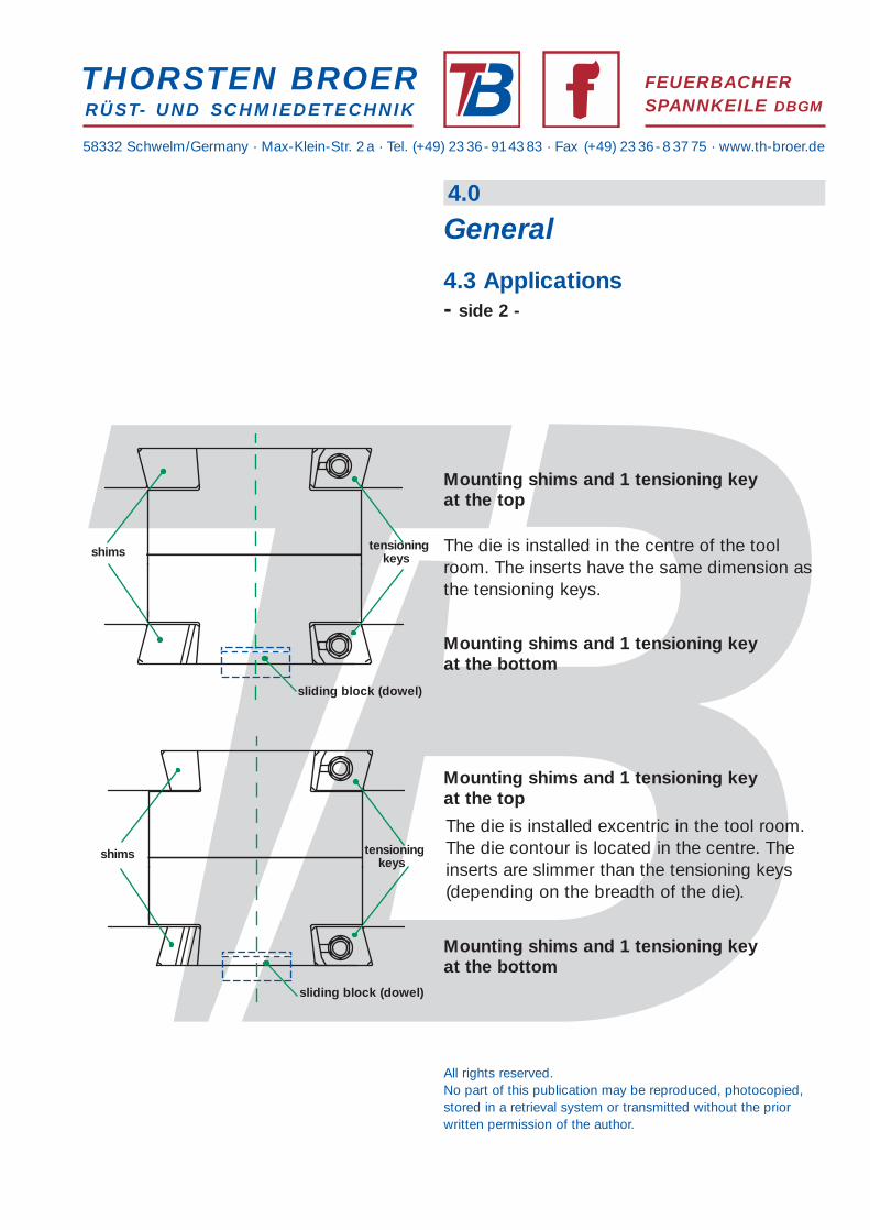
The die is installed in the centre of the toolroom. The inserts have the same dimension asthe tensioning keys.
The die is installed excentric in the tool room.The die contour is located in the centre. Theinserts are slimmer than the tensioning keys(depending on the breadth of the die).
Mounting shims and 1 tensioning keyat the top
Mounting shims and 1 tensioning keyat the top
Mounting shims and 1 tensioning keyat the bottom
Mounting shims and 1 tensioning keyat the bottom

58332 Schwelm/Germany · Max-Klein-Str. 2 a · Tel. (+49) 23 36-9143 83 · Fax (+49) 23 36-8 37 75 · www.th-broer.de
THORSTEN BROERRÜST- UND SCHMIEDETECHNIK
FEUERBACHERSPANNKEILE DBGM
The threads in tensioning screws as used by us have an altered root radius for technical reasons. The threads in the nuts correspond to the respective DIN standards.
Die Root Radius Inner Diameter of Diefor Recutting (min)
W16 x 1/11“ R 0,4 13,9 mmM18 R 0,6 16,1 mmM20 R 0,6 18,1 mmM22 R 0,6 20,1 mmM24 R 0,6 21,3 mmW7/8“ x 1/9“ R 0,6 20,4 mmW1“ R 0,8 23,1 mmM27 R 0,8 24,9 mmM30 R 0,8 27,2 mm
If you wish, you can purchase the respective threading dies for improving the tensioningscrews from us.
All rights reserved.No part of this publication may be reproduced, photocopied,stored in a retrieval system or transmitted without the priorwritten permission of the author.
4.0
General
4.4 Taps / Threading Die

58332 Schwelm/Germany · Max-Klein-Str. 2 a · Tel. (+49) 23 36-9143 83 · Fax (+49) 23 36-8 37 75 · www.th-broer.de
THORSTEN BROERRÜST- UND SCHMIEDETECHNIK
FEUERBACHERSPANNKEILE DBGM
Mounting of Tools
The following tools are required forthe proper mounting of Feuerbachertensioning keys:
-clutched screw driver or ratchet(for mounting or dismounting)
-torque spanner up to approx. 800 Nm
-a long spanner socket (min 100mm)with the right width across flats, withthe thread of the tensioning screwbeing exposed inside
Tools / Auxiliary Materials for Service andMaintenance
Please refer to the separate listing for theexact dimensioning of tools for improving the tensioning screw and nut within thescope of servicing.
Only graphite or Cu-containing greasessuited for warm operation should be usedas lubricants.
We will be pleased to assist you with thepurchase of all appropriate tools andauxiliary materials.
4.0
General
4.5 Tools / Auxiliary Materials
All rights reserved.No part of this publication may be reproduced, photocopied,stored in a retrieval system or transmitted without the priorwritten permission of the author.

58332 Schwelm/Germany · Max-Klein-Str. 2 a · Tel. (+49) 23 36-9143 83 · Fax (+49) 23 36-8 37 75 · www.th-broer.de
European Union
Within the European Union it is permit-ted to declare:Feuerbacher Tensioning Keys and allSpare Parts for Feuerbacher TensioningKeys under the following commoditycode:
8466 103 9000
The respective weights can estimated.
Customs Areas outside the EU
Outside the EU the following customs number isto be indicated:Feuerbacher Tensioning Keys and Full SpareParts Packs for Feuerbacher Tensioning Keys:
8466 103 9000
In case of delivery of individual spare parts, thefollowing customs numbers are to be used:
Tensioning Screw 7318 159 0990Nut 7318 163 0990Taper Pin 7318 240 0900Cup Spring 7320 903 0900Spherical Disc 7318 163 0990Guidance Socket 7318 220 0900Damper / Damper Plate 7326 909 7900Retaining Ring 7318 210 0900Distance Ring 7318 220 0900
THORSTEN BROERRÜST- UND SCHMIEDETECHNIK
FEUERBACHERSPANNKEILE DBGM
All rights reserved.No part of this publication may be reproduced, photocopied,stored in a retrieval system or transmitted without the priorwritten permission of the author.
4.0
General
4.6 Customs Number orCommodity Codes for FeuerbacherTensioning Keys and Spare Parts

58332 Schwelm/Germany · Max-Klein-Str. 2 a · Tel. (+49) 23 36-9143 83 · Fax (+49) 23 36-8 37 75 · www.th-broer.de
THORSTEN BROERRÜST- UND SCHMIEDETECHNIK
FEUERBACHERSPANNKEILE DBGM
copyright © 2005Thorsten Broer Rüst- undSchmiedetechnik e.K. Schwelm,Germany
All rights reserved.
The tensioning keys of versions ”D”, ”TD”, ”SB”und ”DK” and their details are all protected byutility patents. The tensioning keys of versions ”D”, ”TD”, ”SB”und ”DK” and their component parts must notbe copied. They are our exclusive intellectualproperty.
The terms ”Feuerbacher Tensioning Key”and the Feuerbacher logo are our registeredtrademarks.
Without our prior written consent, it is notallowed to reproduce any part of this publica-tion, store it in databases or distribute it in anyother form or by means of any other procedures(electronical, mechanical, photocopies, photo-graphs or other procedures).
We reserve the right to make occasionalamendments to the information provided inthis publication without prior notice.
FEUERBACHERSPANNKEILE DBGM
4.0
General
4.7 Utility Patents and Trademarks