Embed Size (px)
Citation preview

Three-dimensional stress analyses in composite laminateswith an elastically pinned hole
B. Yang a, E. Pan a, F.G. Yuan b,*
a Structures Technology, Inc., 543 Keisler Dr., Suite 204, Cary, NC 27511, USAb Department of Mechanical and Aerospace Engineering, North Carolina State University, Raleigh, NC 27695, USA
Received 26 December 2001; received in revised form 23 September 2002
Abstract
We present a three-dimensional (3-D) stress analysis for composite laminates with an elastically pinned circular hole.
The effects of friction, bearing force and bypass loading on the stress redistribution are studied in detail. The numerical
approach is based on a multilayer boundary element method (MLBEM), a non-traditional BEM particularly designed
for anisotropic composite laminates, coupled with the traditional BEM for the pin filling the hole. The unique char-
acteristic of the MLBEM is that the fundamental solution employs Green�s functions that satisfy the interfacial con-
tinuity conditions and top- and bottom-surface traction-free and symmetry conditions. This fundamental solution
allows us to design a BE scheme without involving discretization on the interfaces and surfaces unless the laminates are
imposed by different boundary conditions. Consequently, in this case of pinned joint, only the hole surface among the
composite boundary and interfaces needs to be discretized. A Coulomb-type friction law is used to simulate the fric-
tional contact interaction between the composite and pin. To solve the frictional contact problem, an iterative scheme of
successive over-relaxation has been proposed where the contact location and frictional contact condition are deter-
mined at the same time in the iteration solution. By applying the MLBEM, stress analyses are performed for a laminate
plate with the stacking sequence ð0=� 45=90Þs. The issues of engineering interests, such as the loading-sequence and
cycling dependencies of stress state due to the presence of friction, are addressed. The solutions, shown by complicated
contact maps and stress states around the hole, suggested that a 3-D approach to pinned composite joints is necessary
for the interpretation of the underlying physics.
� 2002 Published by Elsevier Science Ltd.
Keywords: Three-dimensional stress analysis; Composite laminates; Bolted joint; Bearing and bypass loading; Frictional contact;
Boundary element method
1. Introduction
Owing to their unique light weight/high strength feature, composite laminates have been extensively usedin various engineering structures, in particular, in aircraft and space structures. The structural composites
International Journal of Solids and Structures 40 (2003) 2017–2035
www.elsevier.com/locate/ijsolstr
* Corresponding author. Tel.: +1-919-515-5947; fax: +1-919-515-5934.
E-mail address: [email protected] (F.G. Yuan).
0020-7683/02/$ - see front matter � 2002 Published by Elsevier Science Ltd.
doi:10.1016/S0020-7683(02)00523-1

are commonly jointed by fastening, bonding, or a combination of these two for transferring load from one
component to the other. Each joint method has its own advantages and deficiencies (Lubin, 1982; Schwartz,
1984).
It is well known that stress concentrations near the fastener holes could initiate delamination or othertypes of damage modes, which could then lead to final failure (Persson et al., 1998). Apart from the ex-
perimental approach (e.g., Daniel et al., 1974), various analytical methods have been proposed to examine
the stress field around an open hole, such as the boundary layer method (Tang, 1977, 1979), the linear
laminate finite element method (FEM) (Waszczak and Cruse, 1971; Soni, 1981), the three-dimensional
(3-D) discrete layer FEM (Rybicki and Hopper, 1973; Rybicki and Schmuesser, 1976; Nishioka and Atluri,
1982; Raju and Crews, 1982), and the spline variational method (Iarve, 1996). More recently, an efficient
and accurate non-traditional multilayer boundary element method (MLBEM) has been proposed by the
authors for the stress analysis around an open hole in composite laminates (Pan et al., 2001).The mechanical behavior of a composite laminate structure with filled mechanical fastener is more
complicated than that in the open hole case. While a comprehensive review was given by Camanho and
Matthews (1997), an experimental program was conducted by Ireman et al. (2000) in order to measure and
characterize the development of damage in the vicinity of fastener holes in graphite/epoxy composite
laminates. Also, several simplified models were proposed to numerically study the stress field and failure
processes in mechanically fastened joints in composite laminates. For example, Dano et al. (2000) proposed
a two-dimensional (2-D) FEM model to predict the response of fastener-loaded composite plate, where the
fastener is assumed to be rigid. The traditional 2-D BEM has also been proposed recently to analyze similarproblems by Lie et al. (2000) and Lin et al. (2000), with the fastener treated as a one-dimensional spring in
the former and as a rigid medium in the latter. The 3-D FEM analyses were carried out by Chen et al.
(1995), Ireman (1998), and Persson et al. (1998). In these studies, the fastener was assumed to be elastic and
no friction was allowed along the interface between the fastener and composite except the study by Ireman
(1998). In a similar study, Iarve (1997) proposed a B-spline approximation approach with no-friction as-
sumption. On the other hand, Marshall et al. (1989) using the FEM concluded that the pin-hole contact
friction is as equally important as the laminate stiffness to the stress and failure behavior of composite
laminates.In this article, we propose an efficient and accurate numerical method for the analysis of the mechanical
behavior of a composite laminate plate with an elastic fastener in a circular hole under a bearing force on
the fastener and/or a bypass loading in the composite. Each ply of the composite laminates is assumed to
be generally anisotropic. The fastener is considered as isotropic. The interfaces between the lamina plies
are assumed to be perfectly bonded. The interaction between the composite and fastener is followed by a
Coulomb-type friction law. The problem is solved by using a novel 3-D boundary element formulation, in
which the fundamental solution satisfies the interfacial continuity conditions and the traction-free and
symmetry conditions on the top and bottom surfaces (Yuan et al., in press; Pan et al., 2001; Yang andPan, 2002). Consequently, only the hole surface of the composite plate needs to be discretized. This
leads to a substantial reduction of the numerical approximations and the resulting system of discretized
equations is much smaller compared to that in the FEM and the conventional BEM. To simulate the non-
linear interaction and predict the unknown frictional contact zone between the composite and the pin, an
efficient iterative scheme of successive over-relaxation is proposed. Numerical examples are then car-
ried out for a laminate plate with the stacking sequence ð0=� 45=90Þs. It is shown that a finite fric-
tion coefficient along the hole has substantial effects on the stress redistribution. It is further shown
that the contact stress state in different plies can be very different due to the stiffness difference in theplies. This suggested that a 3-D approach of the laminate pinned joint is necessary. Finally, we observed
that the loading sequence (first bearing force and then bypass loading, and vice versa) and cycling has
only a slight influence on the final stress distribution in the case of perfect fitting between the hole
and pin.
2018 B. Yang et al. / International Journal of Solids and Structures 40 (2003) 2017–2035

2. Problem formulation
2.1. Problem
We consider a composite laminate plate with a circular hole, as shown in Fig. 1a. The plate thickness
is denoted by H , and the length and width by L and W respectively. The left lateral surface of the plate is
fixed. The right lateral surface is attached to a rigid block, which can move without rotation uniaxially.
The hole of radius R is filled with a cylindrical pin without clearance. The other parts of the plate surface are
free of traction. The pin, which symmetrically stick out of the plate surfaces, are fixed at the ends. The
lateral surface is initially free of traction and may partially turn in contact with the hole surface upon
loading.
Initially, the plate and pin are in the stress-free state. Upon a uniaxial force T applied to the rigid block,the plate is loaded, and consequently the hole surface is displaced and partially turns in contact with pin
surface. The resulting displacement at the right lateral surface of the plate is denoted by U . The resulting
force between the plate and pin is denoted by 2F , and called a bearing force. A bypass straining on the
system is defined as U=L. An equivalent bypass loading is defined as ðT � F Þ=W . If W � R, the magnitude
of F should become trivial relative to that of T . Also, if L� R, the force T should be distributed uniformly
in the horizontal direction on the right lateral surface of the plate. When all these conditions hold and our
interest focuses on the local stress field around the hole, the above configuration, often found in laboratory
tests, may be simulated by an infinite laminate plate problem, as described next.Consider an infinite laminate plate with a pinned circular hole, as shown in Fig. 1b. A Cartesian co-
ordinate system, (x1; x2; x3), and a cylindrical coordinate system, (r; h; x3), with r ¼ ðx21 þ x22Þ1=2
and
h ¼ tan�1ðx2=x1Þ, are established. The origin is located at the hole center on the plate bottom surface. The
pin is assumed to be isotropic and linearly elastic. The laminates are assumed to be anisotropic and linearly
elastic and are generally dissimilar from one another. The interfaces between the laminae are perfectly
bonded. This system is initially in the stress-free state. The laminate plate is then subjected to a remote
uniform straining, e111, together with zero stress components r13i (i ¼ 1, 2, 3) and zero average stress
components r112 and r1
22 over the laminae. By applying the classical laminate theory, where the condition ofuniform fields in each lamina and condition of continuous in-plane strain components across an interface
are imposed, these remote fields, r1 and �1, which are assumed to be unaffected by the hole deformation,
can be determined for every lamina completely. Corresponding to the previous configuration, e111 ¼ U=L. Inaddition, the pin is pushed against the hole surface by a symmetric load of 2F , F on each end. Friction
between the hole and pin surfaces is considered and the interaction is followed by a Coulomb-type friction
law. When the friction is present, the loading sequence of applying e111 and F may affect the stress state in
the laminates. In the case, cycling of the loads may also play a role in redistributing the stress field, exhi-
biting a loading-history effect.
Fig. 1. Composite laminates with an elastically pinned circular hole: (a) a finite geometry; (b) an infinite plate approaching (a).
A Cartesian coordinate system, (x1; x2; x3), and a cylindrical coordinate system, (r; h; x3), are established for the plate and pin system.
B. Yang et al. / International Journal of Solids and Structures 40 (2003) 2017–2035 2019
2.2. Boundary integral-equation formulation
A boundary integral-equation (BIE) formulation is used to describe the mechanical behavior of the
composite system coupled with an elastic pin through frictional contact. The displacement uðcÞi at a point Xin the laminate plate can be expressed by an integral of weighted displacement uðcÞj and traction pðcÞj along
the plate boundary SðcÞ, as
cðXÞ½uðcÞi ðX Þ � u1i ðX Þ ¼ZSðcÞ
fu�ðcÞij ðX ; xÞ½pðcÞj ðxÞ � p1j ðxÞ � p�ðcÞij ðX ; xÞ½uðcÞj ðxÞ � u1j ðxÞgdSðxÞ; ð1Þ
where cðXÞ ¼ 1 if X is interior, and 0.5 if X on the boundary (except at the corners), u1j and p1j are thehomogeneous solutions in the plate (if without the hole) under the far-field straining, and the repeated
subscript index implies the conventional summation over its range unless suspended explicitly. In addition,
u�ðcÞij and p�ðcÞij are the fundamental solutions of displacement and traction specially designed for anisotropic
composite laminates, as summarized in Appendix A (Yuan et al., in press; Pan et al., 2001; Yang and Pan,
2002).
It should be remarked that the above fundamental solutions (i.e., Green�s functions), derived within the
framework of extended Stroh formalism and Fourier transforms, can be designed to specifically satisfy the
traction-free (and/or symmetry) conditions on the plate surfaces as well as the continuity conditions ofdisplacement and traction across the interfaces. Because the surfaces where the boundary conditions are
satisfied in the fundamental solutions do not need discretization in the BIE formulation using these so-
lutions as integral kernels, the effective boundary, SðcÞ, can then be reduced to the hole surface in the present
problem of pinned joint. Consequently, the numerical approximations in the BEM to solve the laminate
plate problem are reduced significantly in comparison to the conventional BEM and other domain-based
FEM (Pan et al., 2001).
Similarly, the displacement uðpÞi at an arbitrary point in the pin can be expressed by an integral of
weighted displacement uðpÞj and traction pðpÞj along the pin boundary SðpÞ, as
cðXÞuðpÞi ðX Þ ¼ZSðpÞ
fu�ðpÞij ðX ; xÞpðpÞj ðxÞ � p�ðpÞij ðX ; xÞuðpÞj ðxÞgdSðxÞ; ð2Þ
where cðXÞ means in the same way as above for the laminate plate, and u�ðpÞij and p�ðpÞij are the Kelvin�sfundamental solutions of displacement and traction respectively for linear isotropic elastic solids in full
space (Love, 1944; Brebbia et al., 1984).
The fields ðuðcÞ; pðcÞÞ in the composite and ðuðpÞ; pðpÞÞ in the pin are separated unless the hole and pinsurfaces turn in contact. When it prevails, these fields, and thus Eqs. (1) and (2), are coupled through a law
that describes the contact interaction. In this work, a Coulomb-type friction law is considered, as described
next. The coupling of Eqs. (1) and (2) by the friction law, and its numerical implementation, will be des-
cribed in a later section.
2.3. Frictional contact
The frictional contact between the hole and pin surfaces is modeled by a local Coulomb-type friction law.
Suppose that two smooth surfaces are in conformal contact at a reference point x, as shown in Fig. 2. The
two opposite physical points that are in contact at x are distinguished by designating respectively as the
master and slave points, xþ and x�. The corresponding surfaces are called the master and slave surfaces,
respectively. The local Cartesian coordinate system, (n; t1; t2), is established with the origin located at x. Thenormal axis, n, coincides with the outward normal of the master surface at xþ.
2020 B. Yang et al. / International Journal of Solids and Structures 40 (2003) 2017–2035

The non-penetration condition of the master and slave surfaces requires
wnðxÞP 0; ð3Þwhere wn is the normal component of displacement difference across the surfaces, wðxÞ � uðx�Þ � uðxþÞ. Ifthe surfaces are in contact, wn ¼ 0. If they are separated, wn > 0. When the separation occurs, the surfacesare assumed to be in traction-free condition.
When the surfaces are in contact, i.e., wn ¼ 0, a Coulomb-type friction law is assumed to describe the
frictional interaction between them, written by
pa ¼ �fpndwa
ds; ð4Þ
where the Greek subscript a takes value from 1 to 2, corresponding to the local tangential coordinates t1 andt2 respectively, f is the static friction coefficient, and s � jwj. The law states that the frictional shear traction
is proportional to the pressure (�pn) in magnitude, and opposite to the tangent of relative sliding displace-
ment trajectory. Due to the dependence of the frictional force on trajectory tangent of relative displacement,
a loading-history effect is inherent in the present formulation of the pinned composite joint.
3. Iterative boundary element method of successive over-relaxation
3.1. Mesh and discrete boundary element equations
The fundamental solution for laminate plate containing dissimilar plies, used in the present BIE for-
mulation, satisfies the continuity conditions of displacement and traction across the interfaces and the
traction-free and/or symmetry conditions on the top and bottom surfaces (Yuan et al., in press; Pan et al.,
2001; Yang and Pan, 2002). The partial satisfaction of interfacial and boundary conditions in the funda-mental solution allows us to design a BE scheme without involving discretization on those interfaces and
surfaces unless the laminates are imposed by a different boundary condition. Thus, in the present case of
pinned joint, only the hole surface among the plate surfaces needs to be discretized. Meanwhile, because the
Kelvin�s fundamental solution used in the BIE formulation of the pin refers to the full space, the entire
boundary of the pin needs to be discretized. All of the elements are of the constant type, assuming uniform
fields within each element and a single node located at the center. Note that the elements and nodes on the
hole surface match with those on the vertical surface of the pin. The nodes on the hole surface and those on
the pin surface are numbered separately.A field quantity, qðxÞ, in each of the constant elements may be approximated by the nodal value, qn, at
the element center, written as
qðxÞ ¼ qn; as x 2 the nth element: ð5Þ
Fig. 2. Two smooth surfaces in conformal frictional contact at point x, as designated as the master (þ) and slave ()) surfaces res-pectively. A local Cartesian coordinate system, (n; t1; t2) is established, with n being the outward normal of the master surface at x.
B. Yang et al. / International Journal of Solids and Structures 40 (2003) 2017–2035 2021

By substituting the approximations for displacement and traction into Eqs. (1) and (2), a discrete version of
these BIEs are obtained, namely, the discrete BE equations, as
cðXmÞ½uðcÞmi � u1mi ¼
XN ðcÞ
n¼1
½gðcÞmnij ðpðcÞnj � p1nj Þ � hðcÞmnij ðuðcÞnj � u1n
j Þ; ð6Þ
cðXmÞuðpÞmi ¼XN ðpÞ
n¼1
½gðpÞmnij pðpÞnj � hðpÞmnij uðpÞnj ; ð7Þ
where N ðcÞ and N ðpÞ are the total numbers of nodes for the composite plate and the pin respectively, and the
conventional summation over repeated index does not apply to the superscript indices. The influence co-
efficients, gmnij and hmnij , are given by
gmnij ¼ZSnu�ijðXm; xÞdSðxÞ; ð8Þ
hmnij ¼ZSnp�ijðX
m; xÞdSðxÞ; ð9Þ
valid for both of the composite plate and pin, where Sn is the element where the nth node is located. The
above equations can be evaluated analytically for a constant element for the isotropic elastic pin (Kuriyama
et al., 1995). However, their evaluation for the anisotropic laminate plate has to be carried out numericallyand this is complicated by involving multidimensional integrals and various singularities (Pan et al., 2001;
Yang and Pan, 2002).
If the source point, Xm is located on the boundary, Eqs. (6) and (7) then involve boundary quantities only
and can be used to formulate a numerical scheme to solve the problem given appropriate boundary and
initial conditions. The initial condition is needed due to the involvement of virtual time derivative (i.e.,
tangent derivative of a particle trajectory) in the description of the frictional contact (Eq. (4)). In the present
work, an iterative scheme of successive over-relaxation is developed to solve the complicated problem of
3-D frictional contact between different bodies, based on the previous work by Yang and Ravi-Chandar(1998), as described next.
3.2. Iterative scheme of successive over-relaxation
Without knowing the contact zone a priori, the present problem of coupled laminate plate and pin
generally requires an iterative procedure to determine the contact zone under the non-penetration condition
(Eq. (3)), not to mention the coupling of tangential traction components to normal traction component
under the Coulomb-type friction law (Eq. (4)). In the literature, to the best knowledge of the authors, the
fast iterative methods developed for medium- and large-scale BE computations (e.g., Merkel et al., 1998)are all for systems without altering the stiffness matrix during the solution process, and hence inapplicable
to the present problem involving the Coulomb-type frictional contact between different bodies. Yang and
Ravi-Chandar (1998) have presented an iterative BE scheme of successive over-relaxation for 2-D single-
body elastostatic problems with similar frictional contact between crack surfaces. Applying the scheme,
Yang et al. (2001) have simulated the fatigue crack growth in a 2-D specimen subjected to thousands of
cycles of fatigue loading at a tolerable cost of CPU time on the moderate-power Personal Computer.
However, the examples they have solved are in a relatively small size of about 200 nodes. In the following,
this method is modified to handle the more complicated 3-D problem in a much larger computational sizeby one order.
2022 B. Yang et al. / International Journal of Solids and Structures 40 (2003) 2017–2035

Let ðuðcÞ; pðcÞÞ and ðuðpÞ; pðpÞÞ be the trial sets of displacement and traction on the boundaries of the plate
and pin, respectively. Substituting them into Eqs. (6) and (7) (now, with Xm located at one of the nodes, and
hence c ¼ 0:5), these equations would not be satisfied in general; instead, one obtains the following re-
siduals:
rðcÞmi ¼XN ðcÞ
n¼1
½gðcÞmnij ðpðcÞnj � p1nj Þ � hðcÞmnij ðuðcÞnj � u1n
j Þ � 0:5ðuðcÞmi � u1mi Þ; m ¼ 1; 2; . . . ;N ðcÞ; ð10Þ
rðpÞmi ¼XN ðpÞ
n¼1
½gðpÞmnij pðpÞnj � hðpÞmnij uðpÞnj � 0:5uðpÞmi ; m ¼ 1; 2; . . . ;N ðpÞ: ð11Þ
If the residuals all are sufficiently close to zero, the trial sets of ðuðcÞ; pðcÞÞ and ðuðpÞ; pðpÞÞ represent an ap-
proximate solution to the problem of the coupled laminate plate and pin. Depending on the boundary
conditions to be prescribed, the following scheme is developed to determine the unknown displacement and
traction components iteratively.
Two types of boundary conditions are encountered in the present problem. One is the regular boundary
condition of displacement, traction, or mixed displacement and traction components. The other is the
contact and separation condition, described by Eqs. (3) and (4), as well as the traction-free condition as-sociated with the separation mode. This second condition is needed at the matching nodes between the hole
and pin surfaces. For the nodes under the regular boundary condition, the displacement component, um;lþ1i ,
if not prescribed as a boundary condition, is calculated by using the results of the lth iteration step by
um;lþ1i ¼ um;li þ xrmi ðu; pÞ=ð0:5þ hmmii Þ ðno sum on iÞ; ð12Þ
where x is an adjustable factor of relaxation. Similarly, the traction component, pm;lþ1i , if not prescribed as a
boundary condition, is calculated by
pm;lþ1i ¼ pm;li � xrmi ðu; pÞ=gmmii ðno sum on iÞ: ð13Þ
The residual, rmi ðu; pÞ, is computed by using the nodal values at the (lþ 1)th iteration step if available, or at
the lth iteration step. Note that the above expressions (Eqs. (12) and (13)) are valid for nodes on both of the
composite plate and the pin.
For the matching nodes between the hole and pin surfaces, either the contact or the separation mode may
be activated. If the contact mode prevails, the equality in Eqs. (3), and (4), are invoked as the boundarycondition at the pair of matching nodes. Otherwise, in the separation mode the traction-free condition is
imposed. For convenience, the local coordinate system, with the normal direction coincident with the
outward normal of the master surface (Fig. 2), is used in the contact case. Furthermore, the master node is
always taken to be on the hole surface, while the slave node to be on the pin surface. In practice, whether
the contact at a pair of matching nodes occurs is determined by the sign of the master-nodal normal
traction component pðmasÞn (¼ �pðslaÞn ) at the lth iterative step: If pðmasÞ;l
n < 0, pressure is present and thus the
contact is assumed to occur between the pair of matching nodes. In this case, the normal traction pðmasÞn at
the (lþ 1)th iteration step is computed by
pðmasÞ;lþ1n ¼ pðmasÞ;l
n � x½rðcÞmmn ðuðcÞ; pðcÞÞ � rðpÞssn ðuðpÞ; pðpÞÞ=ðgðcÞmmnn þ gðpÞssnn Þ; ð14Þ
where the superscript m refers to the master-node number, and the superscript s to the slave-node number.Also, the master-nodal normal displacement component, uðmasÞ
n (¼ uðslaÞn , due to Eq. (3)) at the (lþ 1)th
iteration step is computed by
uðmasÞ;lþ1n ¼ uðmasÞ;l
n þ x½rðcÞmmn ðuðcÞ; pðcÞÞ þ rðpÞssn ðuðpÞ; pðpÞÞ=ð1þ hðcÞmmnn þ hðpÞssnn Þ: ð15Þ
B. Yang et al. / International Journal of Solids and Structures 40 (2003) 2017–2035 2023
Furthermore, in the tangential directions, the sum of the master-nodal and slave-nodal displacement
components at the (lþ 1)th iteration step is computed by
uðmasÞ;lþ1a þ uðslaÞ;lþ1
a ¼ uðmasÞ;la þ uðslaÞ;la þ 2x½rðcÞmma ðuðcÞ; pðcÞÞ þ rðpÞssa ðuðpÞ; pðpÞÞ=ð1þ hðcÞmmaa þ hðpÞssaa Þ
ðno sum on aÞ: ð16Þ
Meanwhile, the difference of the displacement components at the (lþ 1)th iteration step is computed by
�uðmasÞ;lþ1a þ uðslaÞ;lþ1
a ¼ �uðmasÞ;la þ uðslaÞ;la þ 2x½�rðcÞmma ðuðcÞ; pðcÞÞ þ rðpÞssa ðuðpÞ; pðpÞÞ=½1þ hðcÞmmaa þ hðpÞssaa
� ðgðcÞmmaa þ gðpÞssaa ÞfpðmasÞ;lþ1n =slf ðno sum on aÞ; ð17Þ
with
slf ¼sfc if Ds < sfc;Ds otherwise;
�ð18Þ
where Ds ¼ sl � sð0Þ, in which sð0Þ is at a previous (reference) ‘‘time’’ step, and sfc is a numerical parameter,
for instance, taken to be around one ten-thousandth of the average magnitude of Ds. From the computed
sum and difference, the tangential displacement components at the master and slave nodes can be obtained.
Furthermore, the master-nodal tangential traction component pðmasÞa (¼ �pðslaÞa ) at the (lþ 1)th iteration
step is computed, in the discrete form of Eq. (4), by
pðmasÞ;lþ1a ¼ �fpðmasÞ;lþ1
n ðwlþ1a � wð0Þ
a Þ=slf : ð19Þ
If the previously computed pðmasÞ;ln P 0 or updated pðmasÞ;lþ1
n P 0, the separation mode between the pair of
matching nodes is activated. In this case, the sum of master-nodal and slave-nodal displacement compo-
nents at the (lþ 1)th iteration step is computed by
uðmasÞ;lþ1i þ uðslaÞ;lþ1
i ¼ uðmasÞ;li þ uðslaÞ;li þ 2x½rðcÞmmi ðuðcÞ; pðcÞÞ þ rðpÞssi ðuðpÞ; pðpÞÞ=ð1þ hðcÞmmii þ hðpÞssii Þ: ð20Þ
Meanwhile, the difference of master- and slave-nodal displacement components at the (lþ 1)th iteration
step is computed by
�uðmasÞ;lþ1i þ uðslaÞ;lþ1
i ¼ �uðmasÞ;li þ uðslaÞ;li þ 2x½�rðcÞmmi ðuðcÞ; pðcÞÞ þ rðpÞssi ðuðpÞ; pðpÞÞ=ð1þ hðcÞmmii þ hðpÞssii Þ:
ð21Þ
From the computed sum and difference, the displacement components at the master and slave nodes can be
obtained. Furthermore, the nodal tractions on the hole and pin surfaces are simply set to be zero in the
separation mode by the traction-free condition.
4. Numerical results
In this section, we apply the previous iterative MLBEM to examine the problem of composite laminates
with an elastically pinned circular hole. The effects of friction, bearing and bypass loading on the stress
redistribution are studied in detail, based on the infinite plate configuration as shown in Fig. 1b. The issues
of practical interest, such as the loading-history and cycling dependencies of stress state due to the presence
of friction, are addressed. The material properties and the numerical meshes used in the simulation are
described below.The laminate plate contains seven plies of identical orthotropic material with the stacking sequence
ð0=� 45=90Þs. The orthotropic material represents a unidirectional fiber-reinforced composite plate, with
2024 B. Yang et al. / International Journal of Solids and Structures 40 (2003) 2017–2035

the fibers lying in the horizontal plane (Lubin, 1982). The number in the stacking sequence indicates the
in-plane rotation angle of each ply relative to the reference 0�-ply where the fibers lie in the 0� direction. Theelastic constants are given by E1 ¼ 138 GPa, E2 ¼ E3 ¼ 14:5 GPa, l23 ¼ l13 ¼ l12 ¼ 5:86 GPa, and
m23 ¼ m13 ¼ m12 ¼ 0:21. Meanwhile, the isotropic pin is made of Ti–6Al–4V, and the elastic constants aregiven by Ef ¼ 110 GPa, and m ¼ 0:31. The hole radius R is taken to be the normalization length scale. The
plate thickness H ¼ 1:4R, i.e., ply thickness ¼ 0:2R. The length of the pin is 2R.Due to the symmetry of the configuration and materials layup relative to the horizontal middle plane,
only the lower half of the plate and pin system is considered. In the resulting problem, the boundary
condition at the middle plane is imposed to have zero normal displacement component and zero tangential
traction components, and this condition is enforced in the fundamental solutions. Thus, the middle plane as
well as the bottom surface and all interfaces of the plate are not discretized in the BE implementation; only
the hole surface is discretized among the plate boundary. This results in a significant reduction of thenumerical errors and size of the system of equations as compared to the FEM and the conventional BEM.
Similarly, the horizontal middle plane of the pin is imposed to have zero normal displacement component
and zero tangential traction components. The entire surface of the lower-half pin including the circular
middle plane is discretized.
The mesh used in the simulation is described as follows. The hole surface (lower half) is discretized with
21 equal divisions in the thickness direction (i.e., six vertical divisions per ply). In the circumferential di-
rection, 64 equal divisions are used. The elements are of the constant type, assuming uniform fields in each
element and with a single node located at the center. This results in 1344 elements in total for the plate. Thevertical surface of the lower-half pin is discretized with 30 equal divisions in the thickness direction and 64
equal divisions in the circumference, resulting in 1920 elements. Among these elements, those between the
plate top and bottom surfaces are in one-to-one correspondence with those on the hole surface. The circular
middle-plane and bottom surfaces of the pin are discretized with 177 constant elements on either one of
them, as shown in Fig. 3. The total number of elements (nodes) in this coupled system is 3618. The bearing
load, F , holding the pin against the hole surface, is applied to the left (opposite to the x1-axis) uniformly on
the bottom surface of the pin.
When solving this problem on a Personal Computer of 1 GHz speed, it took about 240 min to finish onerun of the complete problem. However, more than one fifth of the time was spent in computing the in-
fluence coefficients. Once the influence coefficients are prepared, a series of simulations under various
loading conditions but with the same geometry and materials layup, can be solved in about 20–40 min each
depending on the loading conditions. Several loading cases are analyzed and discussed below.
Fig. 3. Mesh on the middle plane and bottom surfaces of the pin.
B. Yang et al. / International Journal of Solids and Structures 40 (2003) 2017–2035 2025

4.1. Bearing load
First, a study of the case under only bearing force F , with and without friction between the plate and pin
contact surfaces, is presented. In the simulation, the bearing force F was applied from zero up to 0:01pE1 inone ‘‘time’’ step. To check on the effects of the ‘‘time’’ stepping on the results, the same problem was solved
in five ‘‘time’’ steps, finding no apparent effects. In the frictional case, the friction coefficient, f , was set to be
0.3. The contact and separation condition between the hole and pin surfaces, and variation of stress
components with polar angle and with thickness along the hole edge, are plotted in Figs. 4–8.
The unfolded map of contact condition along the hole surface in the frictional case is shown in Fig. 4.
The dark black color represents the stick contact mode, where the master and slave nodes stick together
when moving in space and the magnitude of frictional shear traction is below the cap value of �fpn set bythe friction law (Eq. (4)). The gray color represents the slip contact mode, where the master and slave nodesslide relative to each other and the magnitude of frictional shear traction reaches the cap value. Meanwhile,
the white color represents the separation mode between these two surfaces. From this map, it can be seen
that the hole surface and pin are in contact at polar angles from 90� to 270� and separated at the rest
section. Also, the frictional contact condition in the plies exhibits a slip–stick–slip pattern, similar to but
more complicated than that observed in the contact of homogeneous bodies (Hills et al., 1993). The lo-
cation of the 2-D stick zone is different due to the different layered orientation in the plies and further
complicated by the interaction of neighboring plies.
Fig. 5 shows the distribution of traction components versus polar angle at the middle planes of the pliesat the hole edge. In the frictionless case, the contact zone is entirely in the slip contact condition, with zero
tangential traction. However, in the frictional case with f ¼ 0:3, the contact pressure profile is altered
especially in the stick contact zone, together with the induction of non-trivial tangential traction. The in-
duced tangential traction shows a peak of magnitude at the stick–slip boundary in the contact zone. Such
variation of shear traction, coupled with the pressure, may raise the concern of developing fretting fatigue
damage (Hills et al., 1993). Obviously, the contact-traction profiles in the plies are complicated, strongly
dependent on the layered orientation. These complicated profiles simply suggest that neither the ‘‘cosine
distribution’’ assumption for the pressure (Wong and Matthews, 1981; Chang, 1986) nor the 2-D plateassumption (Lin et al., 2000) would be appropriate to describe the contact behavior in the composite pinned
joint. Three-dimensional stress analyses are demanded in order for an accurate assessment of strength of
the composite joints.
Fig. 4. Contact condition between the composite and pin under e111 ¼ 0 and F ¼ 0:01pE1, in the case of f ¼ 0:3 (black color––stick
contact zone; gray color––slip contact zone; white color––separation zone).
2026 B. Yang et al. / International Journal of Solids and Structures 40 (2003) 2017–2035

Fig. 6 shows the variation of hoop stress, rhh, versus polar angle at the middle plane of a ply at the holeedge. In comparison of the results with and without friction, it can be seen that the presence of friction
redistributes the hoop stress in and out of the contact zone. In particular, in the 0�-ply, where the failure
mode of splitting at the center of contact (i.e. at polar angle 180�) would prevail, the magnitude of the
responsible hoop stress at that point is reduced significantly by the presence of the friction.
Fig. 5. Variation of the (local) contact traction components (normalized by E1) with polar angle at the middle plane of a ply. The loads
are F ¼ 0:01pE1 and e111 ¼ 0. The cases of f ¼ 0:3 and 0 are studied for comparison. Note that in the case of f ¼ 0, the tangential
components rrh and rrz, whose value is zero, are not shown above.
Fig. 6. Variation of the normalized hoop stress, rrr=E1, with polar angle, at the middle plane of a ply. The loads are F ¼ 0:01pE1 and
e111 ¼ 0. The cases of f ¼ 0:3 and 0 are compared.
B. Yang et al. / International Journal of Solids and Structures 40 (2003) 2017–2035 2027
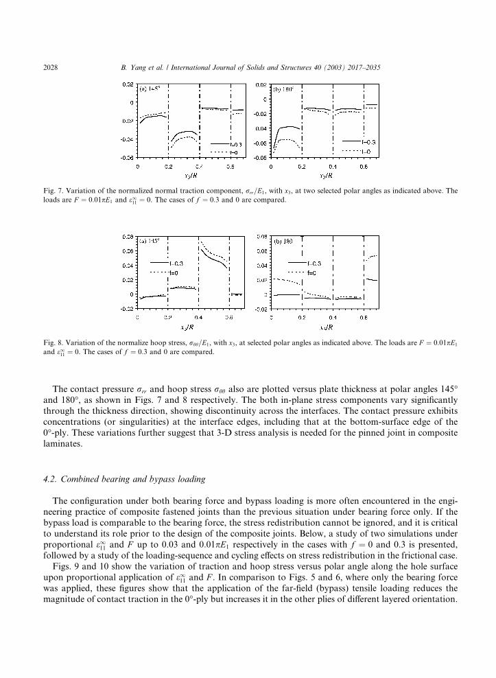
The contact pressure rrr and hoop stress rhh also are plotted versus plate thickness at polar angles 145�and 180�, as shown in Figs. 7 and 8 respectively. The both in-plane stress components vary significantly
through the thickness direction, showing discontinuity across the interfaces. The contact pressure exhibits
concentrations (or singularities) at the interface edges, including that at the bottom-surface edge of the
0�-ply. These variations further suggest that 3-D stress analysis is needed for the pinned joint in composite
laminates.
4.2. Combined bearing and bypass loading
The configuration under both bearing force and bypass loading is more often encountered in the engi-neering practice of composite fastened joints than the previous situation under bearing force only. If the
bypass load is comparable to the bearing force, the stress redistribution cannot be ignored, and it is critical
to understand its role prior to the design of the composite joints. Below, a study of two simulations under
proportional e111 and F up to 0.03 and 0:01pE1 respectively in the cases with f ¼ 0 and 0.3 is presented,
followed by a study of the loading-sequence and cycling effects on stress redistribution in the frictional case.
Figs. 9 and 10 show the variation of traction and hoop stress versus polar angle along the hole surface
upon proportional application of e111 and F . In comparison to Figs. 5 and 6, where only the bearing force
was applied, these figures show that the application of the far-field (bypass) tensile loading reduces themagnitude of contact traction in the 0�-ply but increases it in the other plies of different layered orientation.
Fig. 7. Variation of the normalized normal traction component, rrr=E1, with x3, at two selected polar angles as indicated above. The
loads are F ¼ 0:01pE1 and e111 ¼ 0. The cases of f ¼ 0:3 and 0 are compared.
Fig. 8. Variation of the normalize hoop stress, rhh=E1, with x3, at selected polar angles as indicated above. The loads are F ¼ 0:01pE1
and e111 ¼ 0. The cases of f ¼ 0:3 and 0 are compared.
2028 B. Yang et al. / International Journal of Solids and Structures 40 (2003) 2017–2035

This suggests that the damage mode of bearing (Camanho and Matthews, 1997) may not always beinitiated at the center of contact zone but strongly depend on the laminate layup and ratio of the bear-
ing force to the bypass loading. In addition, the results with and without friction in comparison again
show that the presence of friction suppresses the contact pressure especially in the stick contact zone while
Fig. 9. Variation of the (local) traction components (normalized by E1) with polar angle, at the middle plane of a ply. The loads are
F ¼ 0:01pE1 and e111 ¼ 0:03. The cases of f ¼ 0:3 and 0 are studied for comparison. Note that in the case of f ¼ 0, the tangential
components rrh and rrz, whose value is zero, are not shown above.
Fig. 10. Variation of the normalized hoop stress, rrr=E1, with polar angle, at the middle plane of a ply. The loads are F ¼ 0:01pE1 and
e111 ¼ 0:03. The cases of f ¼ 0:3 and 0 are compared.
B. Yang et al. / International Journal of Solids and Structures 40 (2003) 2017–2035 2029

introducing shear tractions into the system. Whether or not this is appreciable in the practice should depend
on specific application cases.
As discussed before, the Coulomb-type friction model as described in Eqs. (3) and (4) is dependent on
the tangent derivative of relative displacement trajectory between the contact surfaces. It may result in thedependence of final stress state on loading history. In other words, the loading sequence of applying the
bearing force F and bypass loading e111 may affect the stress redistribution around the joint. In order to
address this issue, two simulations were performed under the loading sequences of first applying the bearing
force and then the bypass loading, and vice versa, respectively. The results are plotted in Figs. 11 and 12.
Fig. 11 shows the maps of contact and separation in between the hole and pin surfaces in these two
simulations together with that in the previous simulation. Fig. 12 shows the contact traction and hoop
stress in the middle plane of the 0�-ply.It can be seen that the loading sequence of applying the bearing force F and bypass loading e111 throws a
significant influence on the final contact map. In the case of first applying F and then e111, the contact zone isnearly in complete slip condition. However, in the case where the loading sequence is reversed, the contact
zone devotes a quite large portion to the stick contact condition. Correspondingly, the resulting traction
fields yield differences especially in the tangential traction components between the two cases. The hoop
stress component seems to be unaffected that much by the loading-sequence alternation.
Fig. 11. Effect of loading sequence of applying the bearing force F and bypass loading e111 on contact condition between the composite
and pin: (a) proportional application of F and e111; (b) application of e111 followed by F ; (c) application of F followed by e111. The finale111 ¼ 0:03 and F ¼ 0:01pE1, with f ¼ 0:3. The black color represents stick contact zone, gray color represents slip contact zone, and
white color represents separation zone.
2030 B. Yang et al. / International Journal of Solids and Structures 40 (2003) 2017–2035

Finally, the cycling effect on stress redistribution in the composite joint due to the presence of friction is
studied. To demonstrate this, a simulation was performed with first application of bearing force F up to
0:01pE1, followed by bypass straining e111 up to 0.03. Then, holding F at 0:01pE1, e111 was cycled between 0
and 0.03 for five cycles. The resulting map of contact condition and stress redistribution are plotted in Figs.
13 and 14. It can be seen that the load cycling changes the contact condition by expanding the contact stickzone. It also influences the stress field but in a small magnitude in the present case of perfect fitting between
the hole and pin. It is expected that the cycling of load may play a significant role in stress redistribution
around the composite joint if the pin shows clearance from the hole.
Fig. 12. Effects of loading sequence of applying the bearing force F and bypass loading e111 on contact traction (a–c) and hoop stress
(d) at the middle plane of the 0�-ply. The frictional coefficient f ¼ 0:3. (solid line––proportional application of F and e111; dottedline––application of e111 followed by F ; dashed line––application of F followed by e111).
Fig. 13. Map of contact condition after five cycles of unloading and reloading in terms of e111 upon the first application of bearing force
F followed by bypass straining e111. The map right before the cycling process is shown in Fig. 11c.
B. Yang et al. / International Journal of Solids and Structures 40 (2003) 2017–2035 2031

5. Conclusions
In this paper, we have proposed an efficient and accurate numerical method for analyzing the mechanical
behavior of a composite laminate plate with an elastically pinned circular hole under a bearing force on the
pin and/or bypass loading in the composite. The composite laminates are considered to be generally aniso-
tropic and the pin to be isotropic. The plies are assumed to be perfectly bonded. The contact interaction
between the composite and pin is followed by a Coulomb-type friction law. The problem is solved by using
a novel 3-D boundary element formulation where the fundamental solution employs the Green�s functionfor anisotropic multilayers that satisfies the continuity conditions of displacement and traction across the
interfaces and the traction-free and symmetry conditions on the top and bottom surfaces. To simulate the
non-linear frictional interaction between the composite and pin, an efficient iterative procedure with suc-
cessive over-relaxation is proposed. Numerical examples are carried out for a laminate plate with the
stacking sequence ð0=� 45=90Þs.It has been shown that the contact condition and stress state are complex and very different in
different plies. The presence of friction in the joint reduces the magnitude of contact pressure but
induces non-trivial shear traction. The distribution of other stress components is also altered. It alsoleads to the complicated loading-history dependence of stress state, such as dependence on loading
sequence of applying the bearing force and bypass loading, and on load cycling. However, the effect of
load cycling on stress redistribution is not significant in the present case of perfect fitting between
the composite and pin. The traction distribution in the frictional contact zone raises the susceptibility of
the pinned joint to fretting fatigue, just as in homo- geneous materials. Finally, it is remarked, based
on these numerical results, that a 3-D approach to the pinned composite joints and other similar
and more complicated joint geometries should be used for an accurate assessment of the strength in
general.
Fig. 14. Effects of load cycling on stress redistribution at the middle plane of the 0�-ply. The dotted curves represent the state at first
application of F ¼ 0:01pE1, followed by e111 ¼ 0:03. The solid curves represent the state after five cycles of e111 between 0 and
0.03.
2032 B. Yang et al. / International Journal of Solids and Structures 40 (2003) 2017–2035

Appendix A. Three-dimensional Green�s function for anisotropic multilayers
In this section, the 3-D Green�s function for anisotropic multilayers is summarized, which is derived
within the framework of extended Stroh formalism and Fourier transforms. For details of the theory and
computational aspects, one may refer to Ting (1996), Pan and Yuan (2000), Yuan et al. (in press), and Yang
and Pan (2002), and articles cited therein.
In the formalism, the point-force Green�s functions of displacement and stress first are derived in theFourier transform domain (y1; y2). For a (unit) point force applied in the ith direction at X, the solutions are
given by
euu�ðy1; y2; x3;XÞ ¼ eiyaXabeuu�ðsÞðy1; y2; x3;X3Þ þ ig�1ðAhe�i�ppgx3iVþ Ahe�ipgx3iWÞc; ðA:1Þ
ett�ðy1; y2; x3;XÞ ¼ eiyaXabett�ðsÞðy1; y2; x3;X3Þ þ ðBhe�i�ppgx3iVþ Bhe�ipgx3iWÞc; ðA:2Þ
ess�ðy1; y2; x3;XÞ ¼ eiyaXabess�ðsÞðy1; y2; x3;X3Þ þ ðChe�i�ppgx3iVþ Che�ipgx3iWÞc; ðA:3Þ
where u� � u�ji, t� � ðr�13i; r
�23i; r
�33iÞ, s� � ðr�
11i; r�12i; r
�22iÞ, g together with h are the polar coordinates of
(y1; y2), the superscript (s) indicates a given special solution, and tensors V and W are unknowns to be
determined by boundary conditions. The special solutions may be given to be the infinite-space Green�sfunction (Tonon et al., 2001) or the bimaterial Green�s function (Pan and Yuan, 2000). The eigenvalues piand eigenmatrix A ¼ ða1; a2; a3Þ are related by the following Stroh eigenrelation in an oblique plane
spanned by ðn1 ¼ cos h; n2 ¼ sin h; 0ÞT and ð0; 0; 1ÞT, as
½Qþ piðRþ RTÞ þ p2i Tai ¼ 0; ðA:4Þ
with
Qik ¼ Ciakbnanb; Rik ¼ Ciak3na; and Tik ¼ Ci3k3: ðA:5ÞThe matrix B and C are related to A and the elastic constants (Ting, 1996).
The above expressions of displacement and stress are valid for a homogeneous domain. In the multilayer
system of different homogeneous layers, the unknown tensors V and W for every layer can be derived by
assigning Eqs. (A.1) and (A.2) to different layers and enforcing the interfacial continuity conditions of
displacement and traction and top- and bottom-surface boundary conditions. In our case of composite
laminates of symmetry relative to the horizontal middle plane, the interfacial and boundary conditions are
given by
t ¼ 0; at x3 ¼ h0; ðA:6Þ
um ¼ umþ1 and tm ¼ tmþ1; at x3 ¼ hm; for m ¼ 1; . . . ;M � 1; ðA:7Þ
t1 ¼ t2 ¼ u3 ¼ 0; at x3 ¼ hM ; ðA:8Þwhere m indicates the attachment to the mth layer, M is the number of layers, and hm is the vertical level of
the interfaces including the top and bottom surfaces. Substituting the expressions of displacement and
stress in the transform-domain version of the above equations, one obtains
ett�ðsÞ1 ðh0Þ þ ðB1V1 þ B1he�ip1gðh0�h1ÞiW1Þ ¼ 0; ðA:9Þ
euu�ðsÞm ðhmÞ þ ig�1ðAmhe�i�ppmgðhm�hm�1ÞiVm þ AmWmÞ
¼ euu�ðsÞmþ1ðhmÞ þ ig�1ðAmþ1Vmþ1 þ Amþ1he�ipmþ1gðhm�hmþ1ÞiWmþ1Þ; for m ¼ 1; . . . ;M � 1; ðA:10Þ
B. Yang et al. / International Journal of Solids and Structures 40 (2003) 2017–2035 2033
ett�ðsÞm ðhmÞ þ ðBmhe�i�ppmgðhm�hm�1ÞiVm þ BmWmÞ ¼ ett�ðsÞmþ1ðhmÞ þ ðBmþ1Vmþ1 þ Bmþ1he�ipmþ1gðhm�hmþ1ÞiWmþ1Þ;for m ¼ 1; . . . ;M � 1; ðA:11Þ
egg�ðsÞM ðhMÞ þ ðGMhe�i�ppMgðhM�hM�1ÞiVM þGMWMÞ ¼ 0: ðA:12Þ
In Eq. (A.12), egg� and G are defined by
egg� �t�11 t�12 t�13t�21 t�22 t�23u�31 u�32 u�33
0@
1A and G �
B11 B12 B13
B21 B22 B23
ig�1A31 ig�1A32 ig�1A33
0@
1A: ðA:13Þ
Eqs. (A.9)–(A.12) form a linear system of 2M algebraic equations with 2M unknowns of Vm and Wm.Therefore, Vm and Wm ðm ¼ 1; . . . ;MÞ can be determined for each given set of y1, y2 and X3 by solving this
system of equations. Subsequently, the Green�s displacement and stress are obtained in the transform
domain.
Upon the derivation of the Green�s functions in the transform domain, the physical Green�s functions areevaluated by the Fourier inverse transform over the infinite plane (y1; y2). This has been implemented using
an adaptive quadrature procedure. The efficiency of the evaluation may be dependent on the choice of the
special solutions. These numerical issues are not discussed in the present paper; one may refer to the articles
mentioned earlier.
References
Brebbia, C.A., Telles, J.C.F., Wrobel, L.C., 1984. Boundary Element Techniques: Theory and Applications in Engineering. Springer-
Verlag.
Camanho, P.P., Matthews, F.L., 1997. Stress analysis and strength prediction of mechanically fastened joints in FRP: a review.
Composites Part A. 28A, 529–547.
Chang, F.K., 1986. The effect of pin load distribution on the strength of pin loaded holes in laminated composites. Journal of
Composite Materials 20, 401–408.
Chen, W.H., Lee, S.S., Yeh, J.T., 1995. Three-dimensional contact stress analysis of a composite laminate with bolted joint. Composite
Structures 30, 287–297.
Daniel, I.M., Rowlands, R.E., Whiteside, J.B., 1974. Effects of material and stacking sequence on behavior of composite plates with
holes. Experimental Mechanics 14, 1–9.
Dano, M.L., Gendron, G., Picard, A., 2000. Stress and failure analysis of mechanically fastened joints in composite laminates.
Composite Structures 50, 287–296.
Hills, D.A., Nowell, D., Sackfield, A., 1993. Mechanics of Elastic Contacts. Butterworth-Heinemann Ltd., Oxford, UK.
Iarve, E.V., 1996. Spline variational three-dimensional stress analysis of laminated composite plates with open holes. International
Journal of Solids and Structures 33, 2095–2118.
Iarve, E.V., 1997. Three-dimensional stress analysis in laminated composites with pins based on the B-spline approximation.
Composites Part A 28, 559–571.
Ireman, T., 1998. Three-dimensional stress analysis of bolted single-lap composite joints. Composite Structures 43, 195–216.
Ireman, T., Ranvik, T., Eriksson, I., 2000. On damage development in mechanically fastened composite laminates. Composite
Structures 49, 151–171.
Lie, S.T., Yu, G., Zhao, Z., 2000. Analysis of mechanically fastened composite joints by boundary element methods. Composites Part
B 31, 693–705.
Lin, C.C., Lin, C.H., Wang, J.T.S., 2000. On some aspects of pin-loaded laminates. International Journal of Solids and Structures 37,
599–625.
Love, A.E.H., 1944. A Treatise on the Mathematical Theory of Elasticity. Dover, New York.
Lubin, G., 1982. Handbook of Composites. Van Nostrand Reinhold Company, New York.
Marshall, I.H., Arnold, W.S., Wood, J., Mousley, R.F., 1989. Observations on bolted connections in composite structures. Composite
Structures 13, 133–151.
Merkel, M., Bulgakov, V., Bialecki, R., Kuhn, G., 1998. Iterative solution of large-scale 3D-BEM industrial problems. Engineering
Analysis with Boundary Elements 22, 183–197.
2034 B. Yang et al. / International Journal of Solids and Structures 40 (2003) 2017–2035

Nishioka, T., Atluri, S.N., 1982. Stress analysis of holes in angle-ply laminates: An efficient assumed stress special-hole-element
approach and a simple estimation method. Computers and Structures 15, 135–147.
Pan, E., Yuan, F.G., 2000. Three-dimensional Green�s functions in anisotropic bimaterials. International Journal of Solids and
Structures 37, 5329–5351.
Pan, E., Yang, B., Cai, G., Yuan, F.G., 2001. Stress analyses around holes in composite laminates using boundary element method.
Engineering Analysis with Boundary Elements 25, 31–40.
Persson, E., Madenci, E., Eriksson, I., 1998. Delamination initiation of laminates with pin-loaded holes. Theoretical and Applied
Fracture Mechanics 30, 87–101.
Raju, I.S., Crews Jr., J.H., 1982. Three-dimensional analysis of ½0=90s and ½90=0s laminates with a central circular hole. Composites
Technology Review 4, 116–124.
Rybicki, E.F., Hopper, A.T., 1973. Analytical investigation of stress concentration due to holes in fiber reinforced plastic laminated
plates: three-dimensional models. AFML-TR-73-100, Battelle Columbus labs.
Rybicki, E.F., Schmuesser, D.W., 1976. Three-dimensional finite element stress analysis of laminated plates containing a circular hole.
AFML-TR-76-92, Battelle Columbus Labs.
Schwartz, M.M., 1984. Composite Materials Handbook. McGraw-Hill Book Company, New York.
Soni, S.R., 1981. Stress and strength analysis of bolted joints in composite laminates. In: Marshall, I.H. (Ed.), Composite Structures.
Applied Science Publishers, New York, pp. 50–62.
Tang, S., 1977. Interlaminar stresses around circular cutouts in composites plates under tension. AIAA Journal 15, 1631–1637.
Tang, S., 1979. A variational approach to edge stresses of circular cutouts in composites. In: AIAA Paper 79-0802, 20th AIAA/ASME/
ASCE/AHS, SDM Conference, St. Louis, MO. pp. 326–332.
Ting, T.C.T., 1996. Anisotropic Elasticity. Oxford University, Oxford.
Tonon, F., Pan, E., Amadei, B., 2001. Green�s functions and boundary element formulation for 3D anisotropic media. Computers and
Structures 79, 469–482.
Waszczak, J.P., Cruse, T.A., 1971. Failure mode and strength predictions of anisotropic bolt bearing specimens. Journal of Composite
Materials 5, 421–425.
Wong, S., Matthews, F.L., 1981. A finite element analysis of single and two-hole bolted joints in fibre reinforced elastic. Journal of
Composite Materials 15, 481–491.
Yang, B., Mall, S., Ravi-Chandar, K., 2001. A cohesive zone model of fatigue crack growth in quasibrittle materials. International
Journal of Solids and Structures 38, 3927–3944.
Yang, B., Pan, E., 2002. Efficient evaluation of three-dimensional Green�s functions in anisotropic elastostatic multilayered composites.
Engineering Analysis with Boundary Elements 26, 355–366.
Yang, B., Ravi-Chandar, K., 1998. A single-domain dual-boundary-element formulation incorporating a cohesive zone model for
elastostatic cracks. International Journal of Fracture 93, 115–144.
Yuan, F.G., Yang, S., Yang B. Three-dimensional Green�s functions for composite laminates. International Journal of Solids and
Structures, in press.
B. Yang et al. / International Journal of Solids and Structures 40 (2003) 2017–2035 2035