Embed Size (px)
Citation preview
SCC Inc. Technical Instructions Document No. TS‐3500 January 11, 2019
SCC Inc.
TS‐3D…. Stand‐Alone Deaerator/Surge or Condensate Tanks Three Phase Enclosures
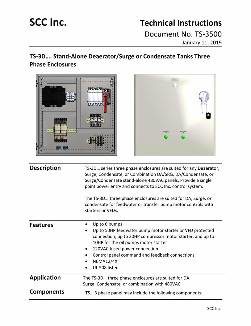
Description
TS‐3D… series three phase enclosures are suited for any Deaerator, Surge, Condensate, or Combination DA/SRG, DA/Condensate, or Surge/Condensate stand‐alone 480VAC panels. Provide a single point power entry and connects to SCC Inc. control system. The TS‐3D… three phase enclosures are suited for DA, Surge, or condensate for feedwater or transfer pump motor controls with starters or VFDs.
Features Up to 6 pumps
Up to 50HP feedwater pump motor starter or VFD protected connection, up to 20HP compressor motor starter, and up to 10HP for the oil pumps motor starter
120VAC fused power connection
Control panel command and feedback connections
NEMA12/4X
UL 508 listed
Application
The TS‐3D… three phase enclosures are suited for DA, Surge, Condensate, or combination with 480VAC
Components
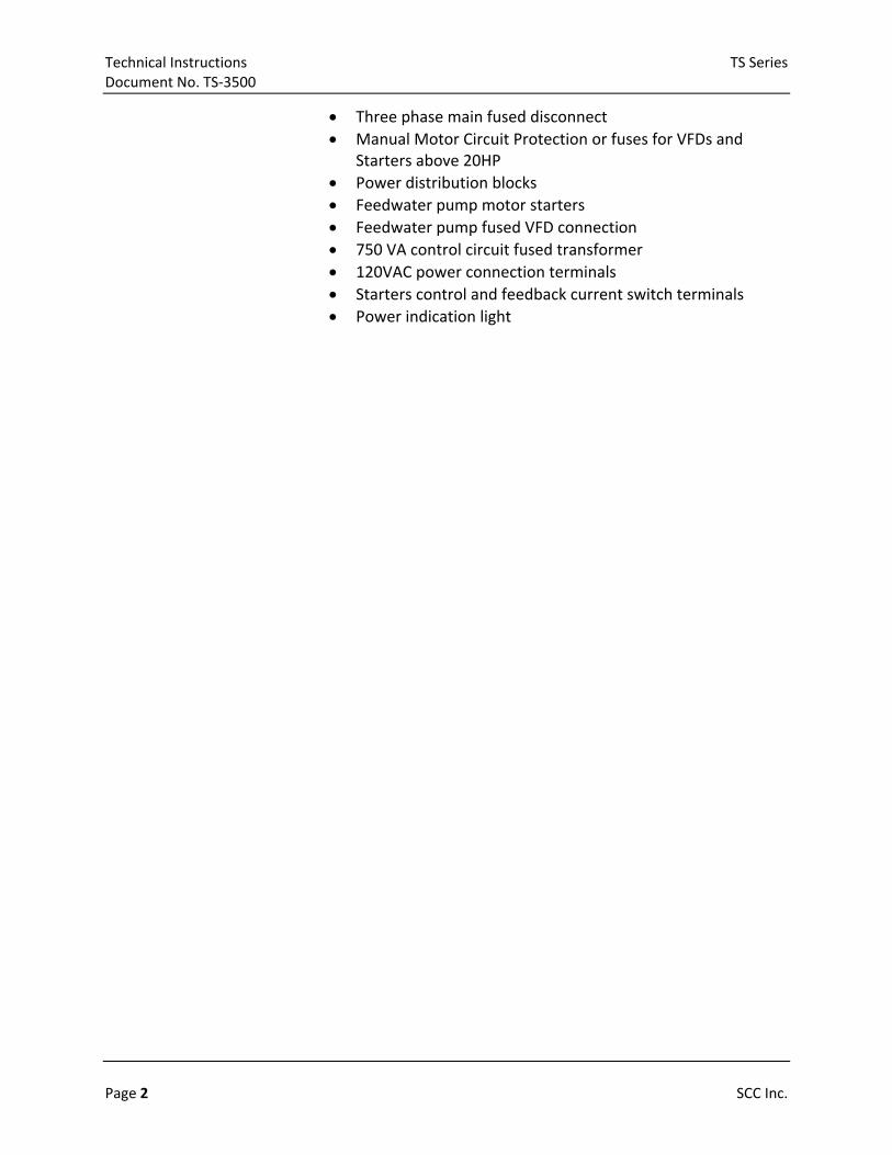
TS… 3 phase panel may include the following components:
Technical Instructions TS Series Document No. TS‐3500
Page 2 SCC Inc.
Three phase main fused disconnect
Manual Motor Circuit Protection or fuses for VFDs and Starters above 20HP
Power distribution blocks
Feedwater pump motor starters
Feedwater pump fused VFD connection
750 VA control circuit fused transformer
120VAC power connection terminals
Starters control and feedback current switch terminals
Power indication light

TS Series Technical Instructions Document No. TS‐3500
SCC Inc. Page 3
Product Part Numbers
TS ‐ 3D ‐ 1 V 4 C S ‐ Y Y Y
DA/SRG/Cond Tank Three Phase 480 VAC Enclosure
Tank Type
1 = Deaerator, feedwater pumps
2 = Surge, transfer pumps
3 = Condensate, transfer pumps
Pumps Motor Starter or VSD Controlled
X = Motor Starter with built in MCB’s (Just for <= 20HP) M = Motor Starter with Fuses and Fuse Holders (Just for > 20HP)
C = Motor Starter with Manual Circuit Breaker (Just for > 20 HP)V = VFD Control with Fuses and Fuse Holders
B = VFD Control with Manual Circuit Breaker
Number of Pumps
2 = Two pumps
3 = Three pumps
4 = Four pumps
5 = Five pumps
6 = Six pumps
Pumps Motor HP Size
A = Pump motor 2 HP G = Pump motor 20 HP
B = Pump motor 3 HP H = Pump motor 25 HP
C = Pump motor 5 HP I = Pump motor 30 HP
D= Pump motor 7.5 HP J = Pump motor 40 HP
E = Pump motor 10 HP K = Pump motor 50 HP
F = Pump motor 15 HP
Enclosure and NEMA rating (Steel, powder coated enclosures)
S = NEMA12/4X no cooling fan, no VFDs installed in enclosure
1 = NEMA1 with cooling fan, drives shipped loose or by others
2 = NEMA12 with cooling fan includes hood over fan, drives shipped loose or by others
4 = NEMA4X with cooling fan includes hood over fan, drives shipped loose or by others
A = NEMA1 with cooling fan, Yaskawa drives installed in enclosure (Future, contact SCC)
B = NEMA12 with cooling fan includes hood over fan, Yaskawa drives installed in enclosure (Future, contact SCC)
C = NEMA4X with cooling fan includes hood over fan, Yaskawa drives installed in enclosure (Future, contact SCC)
Pump Run Indicator Lights
Y = Included in enclosure
N = Not included in enclosure
Main Three Phase Fused Disconnect
Y = Provided in enclosure
Control Transformer 480VAC to 120VAC
Y = 750VA Control Transformer 480VAC to 120VAC provided in enclosure
Technical Instructions TS Series Document No. TS‐3500
Page 4 SCC Inc.
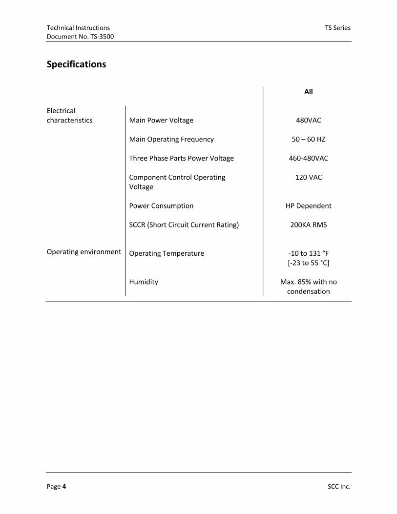
Specifications
All
Electrical characteristics
Main Power Voltage Main Operating Frequency Three Phase Parts Power Voltage
480VAC
50 – 60 HZ
460‐480VAC
Component Control Operating Voltage
120 VAC
Power Consumption SCCR (Short Circuit Current Rating)
HP Dependent
200KA RMS
Operating environment Operating Temperature
‐10 to 131 °F [‐23 to 55 °C]
Humidity
Max. 85% with no condensation

TS Series Technical Instructions Document No. TS‐3500
SCC Inc. Page 5
Field Connections Three Phase Disconnect Switch and Motor Connections with Starter Control

Technical Instructions TS Series Document No. TS‐3500
Page 6 SCC Inc.
Field Connections (continued) Three Phase Disconnect Switch and Motor Connections with Variable Speed Drive

TS Series Technical Instructions Document No. TS‐3500
SCC Inc. Page 7
Field Connections (continued) Connections with SCC Deaerator/Surge/Condensate Control Panel and with Starter Control
Technical Instructions TS Series Document No. TS‐3500
Page 8 SCC Inc.
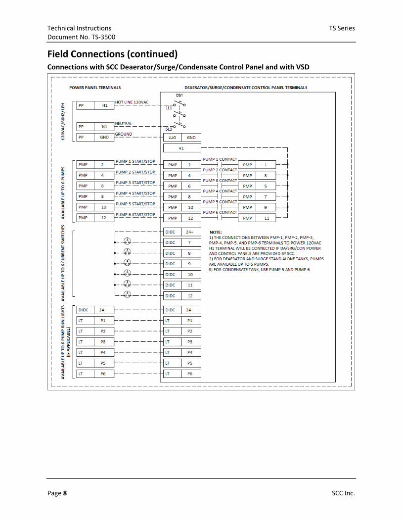
Field Connections (continued) Connections with SCC Deaerator/Surge/Condensate Control Panel and with VSD

TS Series Technical Instructions Document No. TS‐3500
SCC Inc. Page 9
Parts Description Starter Control
1‐ Main Fused Disconnect with locking handle 2‐ Three phase power distribution blocks 3‐ 480VAC to 120VAC control transformer 4‐ Feedwater/Transfer pump starter 5‐ Pump status current switches
6‐ 120VAC feed through and interconnecting
terminals 7‐ Power indication light 8‐ Main fused disconnect handle 9‐ Pump on indication lights
VFD Control
1‐ Main Fused Disconnect with locking handle 2‐ Three phase power distribution blocks 3‐ 480VAC to 120VAC control transformer 4‐ 120VAC feed through and interconnecting
terminals
5‐ Feedwater pump fused VFD connection 6‐ Feedwater pump fused VFD connection 7‐ Power indication light 8‐ Main fused disconnect handle 9‐ Pump on indication lights
1

Technical Instructions TS Series Document No. TS‐3500
Page 10 SCC Inc.
Starters Only, 480VAC, all motors, up to 6 pumps for DA or Surge, and up to 2 Pumps for Condensate tanks
Feedwater Motor: 2HP Motor FLA (Amp): 3.4 Starter Fuse Size (Amp): N/A
Number of Pumps 2 3 4 5 6
Total FLA Calculation (Amp) 10.5 13.9 17.3 20.7 24.1
Disconnect size (Amp) 30A 30A 30A 30A 30A
Main disconnect fuse size (Amp) 10 15 17.5 20 25
Starter Upstream Fuse Holder (Amp) N/A N/A N/A N/A N/A
Enclosure Size 24"X24"X10" 24"X24"X10" 24"X24"X10" 24"X24"X10" 24"X24"X10"
Wire AWG from Disconnect to Distribution TS‐W‐10 TS‐W‐8 TS‐W‐8 TS‐W‐8 TS‐W‐8
Wire AWG Distribution to Fuse Holders TS‐W‐14 TS‐W‐14 TS‐W‐14 TS‐W‐14 TS‐W‐14
Feedwater Motor: 3HP Motor FLA (Amp): 4.8 Starter Fuse Size (Amp): N/A
Number of Pumps 2 3 4 5 6
Total FLA Calculation (Amp) 14 18.8 23.6 28.4 33.2
Disconnect size (Amp) 30A 30A 30A 30A 60A
Main disconnect fuse size (Amp) 15 20 25 30 35
Starter Upstream Fuse Holder (Amp) N/A N/A N/A N/A N/A
Enclosure Size 24"X24"X10" 24"X24"X10" 24"X24"X10" 24"X24"X10" 24"X24"X10"
Wire AWG from Disconnect to Distribution TS‐W‐8 TS‐W‐8 TS‐W‐8 TS‐W‐6 TS‐W‐6
Wire AWG Distribution to Fuse Holders TS‐W‐14 TS‐W‐14 TS‐W‐14 TS‐W‐14 TS‐W‐14
Feedwater Motor: 5HP Motor FLA (Amp): 7.6 Starter Fuse Size (Amp): N/A
Number of Pumps 2 3 4 5 6
Total FLA Calculation (Amp) 21 28.6 36.2 43.8 51.4
Disconnect size (Amp) 30A 360A 60A 60A 100A
Main disconnect fuse size (Amp) 25 30 40 45 50
Starter Upstream Fuse Holder (Amp) N/A N/A N/A N/A N/A
Enclosure Size 24"X24"X10" 24"X24"X10" 24"X24"X10" 24"X24"X10" 24"X24"X10"
Wire AWG from Disconnect to Distribution TS‐W‐8 TS‐W‐8 TS‐W‐6 TS‐W‐6 TS‐W‐4
Wire AWG Distribution to Fuse Holders TS‐W‐12 TS‐W‐12 TS‐W‐12 TS‐W‐12 TS‐W‐12
Feedwater Motor: 7 1/2HP Motor FLA (Amp): 11 Starter Fuse Size (Amp): N/A
Number of Pumps 2 3 4 5 6
Total FLA Calculation (Amp) 29.5 40.5 51.5 62.5 73.5
Disconnect size (Amp) 30A 60A 100A 100A 100A
Main disconnect fuse size (Amp) 30 40 50 70 80
Starter Upstream Fuse Holder (Amp) N/A N/A N/A N/A N/A
Enclosure Size 24"X24"X10" 24"X24"X10" 24"X24"X10" 24"X24"X10" 24"X24"X10"
Wire AWG from Disconnect to Distribution TS‐W‐6 TS‐W‐6 TS‐W‐6 TS‐W‐6 TS‐W‐4
Wire AWG Distribution to Fuse Holders TS‐W‐10 TS‐W‐10 TS‐W‐10 TS‐W‐10 TS‐W‐10
TS Series Technical Instructions Document No. TS‐3500
SCC Inc. Page 11
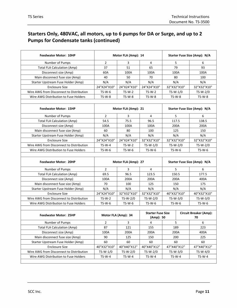
Starters Only, 480VAC, all motors, up to 6 pumps for DA or Surge, and up to 2 Pumps for Condensate tanks (continued)
Feedwater Motor: 10HP Motor FLA (Amp): 14 Starter Fuse Size (Amp): N/A
Number of Pumps 2 3 4 5 6
Total FLA Calculation (Amp) 37 51 65 79 93
Disconnect size (Amp) 60A 100A 100A 100A 100A
Main disconnect fuse size (Amp) 40 50 70 80 100
Starter Upstream Fuse Holder (Amp) N/A N/A N/A N/A N/A
Enclosure Size 24"X24"X10" 24"X24"X10" 24"X24"X10" 32"X32"X10" 32"X32"X10"
Wire AWG from Disconnect to Distribution TS‐W‐6 TS‐W‐2 TS‐W‐2 TS‐W‐1/0 TS‐W‐2/0
Wire AWG Distribution to Fuse Holders TS‐W‐8 TS‐W‐8 TS‐W‐8 TS‐W‐8 TS‐W‐8
Feedwater Motor: 15HP Motor FLA (Amp): 21 Starter Fuse Size (Amp): N/A
Number of Pumps 2 3 4 5 6
Total FLA Calculation (Amp) 54.5 75.5 96.5 117.5 138.5
Disconnect size (Amp) 100A 100A 100A 200A 200A
Main disconnect fuse size (Amp) 60 80 100 125 150
Starter Upstream Fuse Holder (Amp) N/A N/A N/A N/A N/A
Enclosure Size 24"X24"X10" 24"X24"X10" 32"X32"X10" 32"X32"X10" 32"X32"X10"
Wire AWG from Disconnect to Distribution TS‐W‐4 TS‐W‐2 TS‐W‐1/0 TS‐W‐2/0 TS‐W‐2/0
Wire AWG Distribution to Fuse Holders TS‐W‐6 TS‐W‐6 TS‐W‐6 TS‐W‐6 TS‐W‐6
Feedwater Motor: 20HP Motor FLA (Amp): 27 Starter Fuse Size (Amp): N/A
Number of Pumps 2 3 4 5 6
Total FLA Calculation (Amp) 69.5 96.5 123.5 150.5 177.5
Disconnect size (Amp) 100A 200A 200A 200A 400A
Main disconnect fuse size (Amp) 70 100 125 150 175
Starter Upstream Fuse Holder (Amp) N/A N/A N/A N/A N/A
Enclosure Size 24"X24"X10" 32"X32"X10" 32"X32"X10" 40"X32"X10" 40"X32"X10"
Wire AWG from Disconnect to Distribution TS‐W‐2 TS‐W‐2/0 TS‐W‐2/0 TS‐W‐3/0 TS‐W‐3/0
Wire AWG Distribution to Fuse Holders TS‐W‐6 TS‐W‐6 TS‐W‐6 TS‐W‐6 TS‐W‐6
Feedwater Motor: 25HP Motor FLA (Amp): 34 Starter Fuse Size
(Amp): 50 Circuit Breaker (Amp):
70
Number of Pumps 2 3 4 5 6
Total FLA Calculation (Amp) 87 121 155 189 223
Disconnect size (Amp) 100A 200A 200A 200A 400A
Main disconnect fuse size (Amp) 90 125 150 200 225
Starter Upstream Fuse Holder (Amp) 60 60 60 60 60
Enclosure Size 40"X32"X10" 40"X40"X12" 40"X40"X12" 47"X40"X12" 47"X40"X12"
Wire AWG from Disconnect to Distribution TS‐W‐1/0 TS‐W‐2/0 TS‐W‐2/0 TS‐W‐3/0 TS‐W‐4/0
Wire AWG Distribution to Fuse Holders TS‐W‐4 TS‐W‐4 TS‐W‐4 TS‐W‐4 TS‐W‐4
Technical Instructions TS Series Document No. TS‐3500
Page 12 SCC Inc.
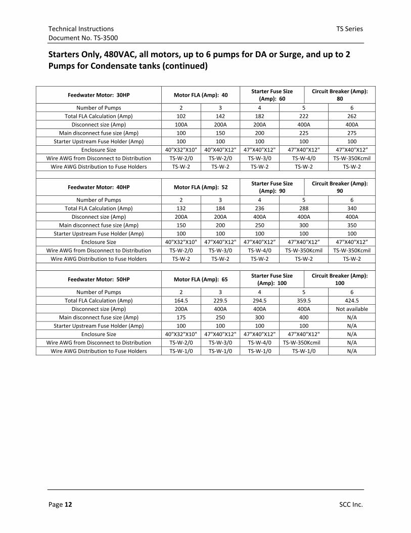
Starters Only, 480VAC, all motors, up to 6 pumps for DA or Surge, and up to 2 Pumps for Condensate tanks (continued)
Feedwater Motor: 30HP Motor FLA (Amp): 40 Starter Fuse Size
(Amp): 60 Circuit Breaker (Amp):
80
Number of Pumps 2 3 4 5 6
Total FLA Calculation (Amp) 102 142 182 222 262
Disconnect size (Amp) 100A 200A 200A 400A 400A
Main disconnect fuse size (Amp) 100 150 200 225 275
Starter Upstream Fuse Holder (Amp) 100 100 100 100 100
Enclosure Size 40"X32"X10" 40"X40"X12" 47"X40"X12" 47"X40"X12" 47"X40"X12”
Wire AWG from Disconnect to Distribution TS‐W‐2/0 TS‐W‐2/0 TS‐W‐3/0 TS‐W‐4/0 TS‐W‐350Kcmil
Wire AWG Distribution to Fuse Holders TS‐W‐2 TS‐W‐2 TS‐W‐2 TS‐W‐2 TS‐W‐2
Feedwater Motor: 40HP Motor FLA (Amp): 52 Starter Fuse Size
(Amp): 90 Circuit Breaker (Amp):
90
Number of Pumps 2 3 4 5 6
Total FLA Calculation (Amp) 132 184 236 288 340
Disconnect size (Amp) 200A 200A 400A 400A 400A
Main disconnect fuse size (Amp) 150 200 250 300 350
Starter Upstream Fuse Holder (Amp) 100 100 100 100 100
Enclosure Size 40"X32"X10" 47"X40"X12" 47"X40"X12” 47"X40"X12” 47"X40"X12”
Wire AWG from Disconnect to Distribution TS‐W‐2/0 TS‐W‐3/0 TS‐W‐4/0 TS‐W‐350Kcmil TS‐W‐350Kcmil
Wire AWG Distribution to Fuse Holders TS‐W‐2 TS‐W‐2 TS‐W‐2 TS‐W‐2 TS‐W‐2
Feedwater Motor: 50HP Motor FLA (Amp): 65 Starter Fuse Size (Amp): 100
Circuit Breaker (Amp): 100
Number of Pumps 2 3 4 5 6
Total FLA Calculation (Amp) 164.5 229.5 294.5 359.5 424.5
Disconnect size (Amp) 200A 400A 400A 400A Not available
Main disconnect fuse size (Amp) 175 250 300 400 N/A
Starter Upstream Fuse Holder (Amp) 100 100 100 100 N/A
Enclosure Size 40"X32"X10" 47"X40"X12" 47"X40"X12" 47"X40"X12" N/A
Wire AWG from Disconnect to Distribution TS‐W‐2/0 TS‐W‐3/0 TS‐W‐4/0 TS‐W‐350Kcmil N/A
Wire AWG Distribution to Fuse Holders TS‐W‐1/0 TS‐W‐1/0 TS‐W‐1/0 TS‐W‐1/0 N/A
TS Series Technical Instructions Document No. TS‐3500
SCC Inc. Page 13
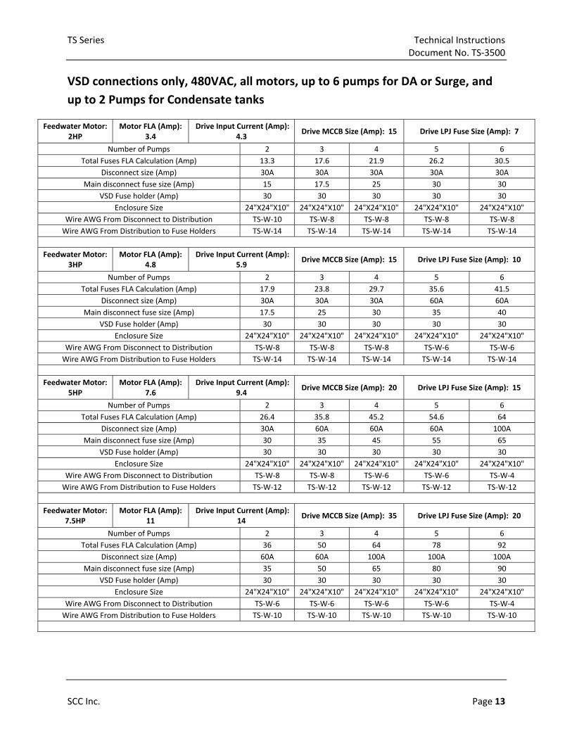
VSD connections only, 480VAC, all motors, up to 6 pumps for DA or Surge, and
up to 2 Pumps for Condensate tanks
Feedwater Motor: 2HP
Motor FLA (Amp): 3.4
Drive Input Current (Amp): 4.3
Drive MCCB Size (Amp): 15 Drive LPJ Fuse Size (Amp): 7
Number of Pumps 2 3 4 5 6
Total Fuses FLA Calculation (Amp) 13.3 17.6 21.9 26.2 30.5
Disconnect size (Amp) 30A 30A 30A 30A 30A
Main disconnect fuse size (Amp) 15 17.5 25 30 30
VSD Fuse holder (Amp) 30 30 30 30 30
Enclosure Size 24"X24"X10" 24"X24"X10" 24"X24"X10" 24"X24"X10" 24"X24"X10"
Wire AWG From Disconnect to Distribution TS‐W‐10 TS‐W‐8 TS‐W‐8 TS‐W‐8 TS‐W‐8
Wire AWG From Distribution to Fuse Holders TS‐W‐14 TS‐W‐14 TS‐W‐14 TS‐W‐14 TS‐W‐14
Feedwater Motor: 3HP
Motor FLA (Amp): 4.8
Drive Input Current (Amp): 5.9
Drive MCCB Size (Amp): 15 Drive LPJ Fuse Size (Amp): 10
Number of Pumps 2 3 4 5 6
Total Fuses FLA Calculation (Amp) 17.9 23.8 29.7 35.6 41.5
Disconnect size (Amp) 30A 30A 30A 60A 60A
Main disconnect fuse size (Amp) 17.5 25 30 35 40
VSD Fuse holder (Amp) 30 30 30 30 30
Enclosure Size 24"X24"X10" 24"X24"X10" 24"X24"X10" 24"X24"X10" 24"X24"X10"
Wire AWG From Disconnect to Distribution TS‐W‐8 TS‐W‐8 TS‐W‐8 TS‐W‐6 TS‐W‐6
Wire AWG From Distribution to Fuse Holders TS‐W‐14 TS‐W‐14 TS‐W‐14 TS‐W‐14 TS‐W‐14
Feedwater Motor: 5HP
Motor FLA (Amp): 7.6
Drive Input Current (Amp): 9.4
Drive MCCB Size (Amp): 20 Drive LPJ Fuse Size (Amp): 15
Number of Pumps 2 3 4 5 6
Total Fuses FLA Calculation (Amp) 26.4 35.8 45.2 54.6 64
Disconnect size (Amp) 30A 60A 60A 60A 100A
Main disconnect fuse size (Amp) 30 35 45 55 65
VSD Fuse holder (Amp) 30 30 30 30 30
Enclosure Size 24"X24"X10" 24"X24"X10" 24"X24"X10" 24"X24"X10" 24"X24"X10"
Wire AWG From Disconnect to Distribution TS‐W‐8 TS‐W‐8 TS‐W‐6 TS‐W‐6 TS‐W‐4
Wire AWG From Distribution to Fuse Holders TS‐W‐12 TS‐W‐12 TS‐W‐12 TS‐W‐12 TS‐W‐12
Feedwater Motor: 7.5HP
Motor FLA (Amp): 11
Drive Input Current (Amp): 14
Drive MCCB Size (Amp): 35 Drive LPJ Fuse Size (Amp): 20
Number of Pumps 2 3 4 5 6
Total Fuses FLA Calculation (Amp) 36 50 64 78 92
Disconnect size (Amp) 60A 60A 100A 100A 100A
Main disconnect fuse size (Amp) 35 50 65 80 90
VSD Fuse holder (Amp) 30 30 30 30 30
Enclosure Size 24"X24"X10" 24"X24"X10" 24"X24"X10" 24"X24"X10" 24"X24"X10"
Wire AWG From Disconnect to Distribution TS‐W‐6 TS‐W‐6 TS‐W‐6 TS‐W‐6 TS‐W‐4
Wire AWG From Distribution to Fuse Holders TS‐W‐10 TS‐W‐10 TS‐W‐10 TS‐W‐10 TS‐W‐10

Technical Instructions TS Series Document No. TS‐3500
Page 14 SCC Inc.
VSD connections only, 480VAC, all motors, up to 6 pumps for DA or Surge, and
up to 2 Pumps for Condensate tanks (continued)
Feedwater Motor HP: 10HP
Motor FLA (Amp): 14
Drive Input Current (Amp): 20
Drive MCCB Size (Amp): 50 Drive LPJ Fuse Size (Amp): 35
Number of Pumps 2 3 4 5 6
Total Fuses FLA Calculation (Amp) 57 77 97 117 137
Disconnect size (Amp) 60A 100A 100A 200A 200A
Main disconnect fuse size (Amp) 60 80 100 120 135
VSD Fuse holder (Amp) 60 60 60 60 60
Enclosure Size 24"X24"X10" 24"X24"X10" 24"X24"X10" 32"X32"X10" 32"X32"X10"
Wire AWG From Disconnect to Distribution TS‐W‐6 TS‐W‐2 TS‐W‐2 TS‐W‐1/0 TS‐W‐2/0
Wire AWG From Distribution to Fuse Holders TS‐W‐8 TS‐W‐8 TS‐W‐8 TS‐W‐8 TS‐W‐8
Feedwater Motor: 15HP
Motor FLA (Amp): 21
Drive Input Current (Amp): 24
Drive MCCB Size (Amp): 60 Drive LPJ Fuse Size (Amp): 40
Number of Pumps 2 3 4 5 6
Total Fuses FLA Calculation (Amp) 66 90 114 138 162
Disconnect size (Amp) 100A 100A 200A 200A 200A
Main disconnect fuse size (Amp) 70 90 115 140 165
VSD Fuse holder (Amp) 60 60 60 60 60
Enclosure Size 24"X24"X10" 24"X24"X10" 32"X32"X10" 32"X32"X10" 32"X32"X10"
Wire AWG From Disconnect to Distribution TS‐W‐4 TS‐W‐2 TS‐W‐1/0 TS‐W‐2/0 TS‐W‐2/0
Wire AWG From Distribution to Fuse Holders TS‐W‐6 TS‐W‐6 TS‐W‐6 TS‐W‐6 TS‐W‐6
Feedwater Motor: 20HP
Motor FLA (Amp): 27
Drive Input Current (Amp): 38
Drive MCCB Size (Amp): 90 Drive LPJ Fuse Size (Amp): 60
Number of Pumps 2 3 4 5 6
Total Fuses FLA Calculation (Amp) 100 138 176 214 252
Disconnect size (Amp) 100A 200A 200A 400A 400A
Main disconnect fuse size (Amp) 100 140 175 225 250
VSD Fuse holder (Amp) 60 60 60 60 60
Enclosure Size 24"X24"X10" 32"X32"X10" 32"X32"X10" 40"X32"X10" 40"X32"X10"
Wire AWG From Disconnect to Distribution TS‐W‐2 TS‐W‐2/0 TS‐W‐2/0 TS‐W‐3/0 TS‐W‐3/0
Wire AWG From Distribution to Fuse Holders TS‐W‐6 TS‐W‐6 TS‐W‐6 TS‐W‐6 TS‐W‐6
Feedwater Motor: 25HP
Motor FLA (Amp): 34
Drive Input Current (Amp): 44
Drive MCCB Size (Amp): 110
Drive LPJ Fuse Size (Amp): 70
Number of Pumps 2 3 4 5 6
Total Fuses FLA Calculation (Amp) 116 160 204 248 292
Disconnect size (Amp) 200A 200A 200A 400A 400A
Main disconnect fuse size (Amp) 120 165 200 250 300
VSD Fuse holder (Amp) 100 100 100 100 100
Enclosure Size 40"X40"X12" 40"X40"X12" 40"X40"X12" 47"X40"X12" 47"X40"X12"
Wire AWG From Disconnect to Distribution TS‐W‐1/0 TS‐W‐2/0 TS‐W‐2/0 TS‐W‐3/0 TS‐W‐4/0
Wire AWG From Distribution to Fuse Holders TS‐W‐4 TS‐W‐4 TS‐W‐4 TS‐W‐4 TS‐W‐4

TS Series Technical Instructions Document No. TS‐3500
SCC Inc. Page 15
VSD connections only, 480VAC, all motors, up to 6 pumps for DA or Surge, and
up to 2 Pumps for Condensate tanks (continued)
Feedwater Motor: 40HP
Motor FLA (Amp): 52
Drive Input Current (Amp): 58
Drive MCCB Size (Amp): 100
Drive LPJ Fuse Size (Amp): 100
Number of Pumps 2 3 4 5 6
Total Fuses FLA Calculation (Amp) 160 218 276 334 392
Disconnect size (Amp) 200A 400A 400A 400A 400A
Main disconnect fuse size (Amp) 175 225 275 350 400
VSD Fuse holder (Amp) 100 100 100 100 100
Enclosure Size 40"X40"X12" 47"X40"X12" 47"X40"X12" 47"X40"X12" 47"X40"X12"
Wire AWG From Disconnect to Distribution TS‐W‐2/0 TS‐W‐3/0 TS‐W‐4/0 TS‐W‐350Kcmil TS‐W‐350Kcmil
Wire AWG From Distribution to Fuse Holders TS‐W‐2 TS‐W‐2 TS‐W‐2 TS‐W‐2 TS‐W‐2
Feedwater Motor: 50HP
Motor FLA (Amp): 65
Drive Input Current (Amp): 71
Drive MCCB Size (Amp): 125
Drive LPJ Fuse Size (Amp): 110
Number of Pumps 2 3 4 5 6
Total Fuses FLA Calculation (Amp) 183 254 325 396 467
Disconnect size (Amp) 200A 400A 400A 400A N/A
Main disconnect fuse size (Amp) 200 250 350 400 N/A
VSD Fuse holder (Amp) 200 200 200 200 N/A
Enclosure Size 40"X40"X12" 47"X40"X10" 47"X40"X12" 47"X40"X12" N/A
Wire AWG From Disconnect to Distribution TS‐W‐2/0 TS‐W‐3/0 TS‐W‐4/0 TS‐W‐350Kcmil N/A
Wire AWG From Distribution to Fuse Holders TS‐W‐1/0 TS‐W‐1/0 TS‐W‐1/0 TS‐W‐1/0 N/A

Technical Instructions TS Series Document No. TS‐3500
Page 16 SCC Inc.
Dimensions Dimensions in inches; millimeters in brackets
24” x 24” x 10” Combustion Enclosure

TS Series Technical Instructions Document No. TS‐3500
SCC Inc. Page 17
Dimensions (continued) Dimensions in inches; millimeters in brackets
32” x 32” x 10” Combustion Enclosure

Technical Instructions TS Series Document No. TS‐3500
Page 18 SCC Inc.
Dimensions (continued) Dimensions in inches; millimeters in brackets
40” x 32” x 10” Combustion Enclosure
TS Series Technical Instructions Document No. TS‐3500
SCC Inc. Page 19
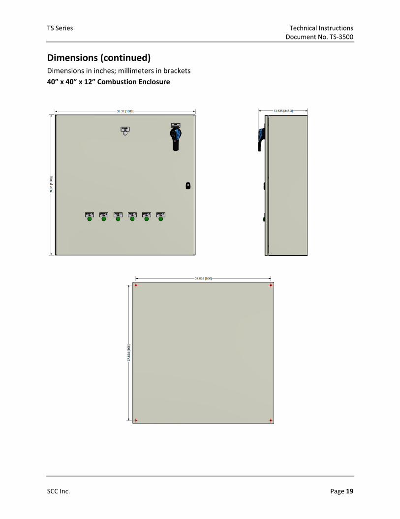
Dimensions (continued) Dimensions in inches; millimeters in brackets
40” x 40” x 12” Combustion Enclosure

Technical Instructions TS Series Document No. TS‐3500
SCC Inc. Your feedback is important to us. If you have Document No. TS‐3500 1250 Lunt Avenue comments about this document, please send them Country of Origin: US Elk Grove Village, IL 60007 to [email protected] Page 20 U.S.A.
Dimensions (continued) Dimensions in inches; millimeters in brackets
47” x 40” x 12” Combustion Enclosure
Information in this publication is based on current specifications. The company reserves the right to make changes in specifications and models as design improvements are introduced. Product or company names mentioned herein may be the trademarks of their respective owners. © 2018 SCC Inc.