Embed Size (px)
Citation preview
International Journal of ISSI, Vol.9 (2012), No.2, pp. 32-38
Ti-Cr-N Coatings Deposited by Physical Vapor Deposition on AISI D6 Tool Steels
M. Akbarzadeh1, A. Shafyei2* and H. R. Salimijazi3
Department of Materials Engineering, Isfahan University of Technology, Isfahan 84156-83111, Iran
-------------------------------------------------------------------------------------------------------------------------------------------------------------------------------------------------Abstract
In this study, physical vapor deposition (PVD) Ti-Cr-N coatings were deposited at two different temperatures 100 and 400ºC on hardened and tempered tool steel substrates. The influence of the applied deposition temperature on the physical and mechanical properties of coatings such as roughness, thickness, phase composition, hardness and Young’s modulus were evaluated. Phase compositions were studied by X-ray diffraction method. Mechanical properties were determined by Nano indentation. The results showed different behavior s in the mechanical properties by changing the deposition temperature. (Ti, Cr)N and TiN coatings consisted of only one solid solution cubic phase, while CrN coatings exhibited hexagonal Cr2N and cubic CrN phases. Mechanical behavior of the (Ti, Cr)N coatings was related to the Ti content and their hardness reduced by decreasing the Ti content. (Ti, Cr)N coatings deposited at high temperature exhibited better mechanical properties compared to the coating deposited at low temperatures.
Keywords: physical vapor deposition, characterization, microstructure, mechanical property, Ti-Cr-N coating. -------------------------------------------------------------------------------------------------------------------------------------------------------------------------------------------------
1. Introduction
The1life time and wear resistance of different instruments and industrial parts can be improved by applying a hard thin film coating on their surfaces. Metal nitride coatings have many unique properties and superior wear resistance properties. Among them, TiN and CrN are superior and are widely used in industries 1). TiN coatings have the NaCl-type crystal structure, possessing advantages of high hardness, high chemical stability, and excellent adhesion to substrates 2). A well-known use for TiN coating is for edge retention and corrosion resistance on machine tooling, such as drill bits and milling cutters, often improving their lifetime by a factor of three or more. A drawback of TiN coating is its limited oxidation resistance at temperatures above 600oC where a TiO2 layer is formed. Due to the large difference in molar volumes.
between TiO2 and TiN, compressive stresses are developed in the oxide layer resulting in spallation and exposure of the nitride to further oxidation 3). CrN coatings are well prominent for their lower coefficient of friction, and excellent oxidation and corrosion resistances, higher ductility and fracture toughness. Therefore, in many cases it replaced to TiN 3-6). The maximum service temperature for TiN and CrN coating
* Corresponding author: Tel: +98 311 3915769 Fax: +98 311 3912862Email: [email protected] Address: Department of Materials Engineering, Isfahan University of Technology, Isfahan Isfahan 84156-83111,Iran1. M.Sc.2. Associate Professor3. Assistant Professor
is 300 and 550°C, respectively. In addition, it has been said that the oxidation resistance of CrN compared to TiN is almost 1000 times higher. Investigation showed that CrN coatings with optimum thickness work much better than TiN coating under equal conditions 1,3,7). The multicomponent coatings have been investigated in order to answer the increasing need for superior mechanical properties in various applications. The multicomponent coatings usually have good physical and mechanical properties and are widely used in various industries 8). Properties of these coatings such as friction coefficient, wear rate, hardness, and toughness could be controlled by the selection of the elements and/or phases forming, their chemical composition and/or volume fractions, and deposition process parameters. These physical quantities are usually influenced by the chemical composition, phase content, and microstructure, which are dependent on the deposition conditions and preparation methods. Recent innovative multi-component coatings increase these properties further e.g. Ti(C,N), (Ti, Al)N, (Ti, Si)N, (Ti, B)N, (Ti, Ag)N, (Ti, Zr)N, (Ti, Nb)N, (Ti, Al, V)N and (Ti, Al, V, Cr, Mo,)N 9-16). An increasing amount of attention is focused on ternary Ti-Cr-N coatings. Researchers have reported that new ternary Ti–Cr–N coatings have high-temperature strength and corrosion compared to CrN and TiN coatings 8,17-23).
These physical quantities are usually influenced by the chemical composition, phase content, and microstructure, which are dependent on the deposition conditions and preparation methods. However, most of these have barely been investigated. The goal of this research was to investigate the influence of deposition temperature on the properties of Ti-Cr-N coatings deposited by PVD.
International Journal of ISSI, Vol.9 (2012), No.2
33
2. Experimental
The substrate AISI D6 tool steel rods with 50 mm diameter were cut in 5 mm thickness disks. The samples were annealed at 980°C followed by quenching in water and tempered at 180°C. The hardness of the sample was obtained 55HRC. Before coating, the substrates were strictly cleaned then ground and polished to the roughness of (Ra) 0.01µm. Cr (99.8% in purity) and Ti (99.6% in purity) were used as target cathodes. Initially, chamber was evacuated to a pressure of 10-6mbar with a diffusion pump before introducing a reactive gas. Then substrates were cleaned by sputtering of argon ions, for 20min at 1Pa argon pressure with the substrate bias at -2000V and arc current of target 300A.
For reactive nitrogen coating deposition, high purity nitrogen gas (99.9%) was reacted with the cathodic arc evaporated species. N2 gas was injected into the vacuum chamber in order to react with Ti and Cr ions to form the metal nitride.
The distance from the target source to the substrate was 200mm. The chamber working pressure was 10-3 mbar. The coating process was carried out for 1h. During ion etch and deposition, the substrates were rotated in a planet-sun fashion. During deposition of (Ti, Cr)N the arc currents of target titanium and chromium were 300A and 80A, respectively. Deposition time was 1h. Coatings were deposited at both low (≈100°C) and standard temperatures (≈400°C). Coating compositions were determined using a Philips XL30 SEM with an EDS attachment. The surface roughness was measured using stylus type (Talysurf Taylor Hobson) instruments. The average surface roughness was measured at five different locations and results were averaged.
X-ray diffraction (performed with a Philips PW3710 diffractometer) using Cu kα radiation was employed to evaluate the phase composition, crystal structure, and crystallographic orientations of the coatings. XRD scans were performed and compared to the Powder Diffraction Files (JCPDS’s) published by the International Centre for Diffraction Data (ICDD).
The crystallite size and micro-strain was evaluated from the X-ray diffraction patterns based on the Scherrer formula 24) that is defined as:
cos Kdλβ θ = (1)
where β is the line broadening at half the maximum intensity (FWHM) in radians, cos K
dλβ θ = is the wavelength,cos K
dλβ θ =
is the diffraction angle, and d is crystallite size.The hardness and Young’s modulus were
measured with nano indentation tests (CSM) which was developed by Oliver and Pharr 25). The maximum indentation depth of 320 nm and load of 3000 µN and maximum loading and unloading rate of 60.00 mN/min was applied. Six indentations on each coating were applied and the average value was presented.
3. Results and discussion
The summary of the deposition process parameters, chemical composition, and thickness of coatings are tabulated in Table 1. The deposition rate is directly related to the evaporator current. The maximum vaporization rate of material is relative to the vapor pressure and is calculated using the Hertz–Knudsen equation:
0.5 *(2 ) ( )eV e
dN a mKT P P Adt
π −= − (2)
where dN is the number of evaporating atoms per cm2 of surface area, P* is the vapour pressure of the material at temperature, m is mass of the vaporized species, P is pressure of the vapour above the surface, K is Boltzmann’s constant, T is absolute temperature and C is constant that depends on the rotational degrees of freedom in the liquid and the vapour. According to Hertz-Knudsen formula, because of lower vapour pressure of chromium compared to titanium, coating thickness of TiN is less than CrN coatings at the same deposition conditions. (Ti, Cr)N coatings have maximum thickness, since two targets were used, simultaneously.
Table 1. Deposition conditions and coating composition
Sample Cr
evaporatorcurrent(A)
Ti evaporatorcurrent (A)
Thickness(µm)
Substrate temperature
(°C)
Cr Content(Cr/(Cr + Ti))
Ti Content(Ti/(Cr + Ti))
a-1 0 300 2.1±0.1 400 0 1
a-2 0 300 1.5±0.1 100 0 1
b-1 80 300 2.8±0.4 400 0.32 0.68
b-2 80 300 3.1±0.1 100 0.35 0.65
c-1 300 80 3.5±0.2 400 0.73 0.27
c-2 300 80 4.5±0.2 100 0.70 0.30
d-1 300 0 2.8±0.1 400 1 0d-2 300 0 2.1±0.1 100 1 0
International Journal of ISSI, Vol.9 (2012), No.2
34
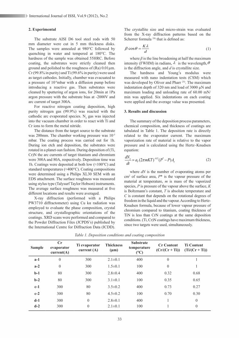
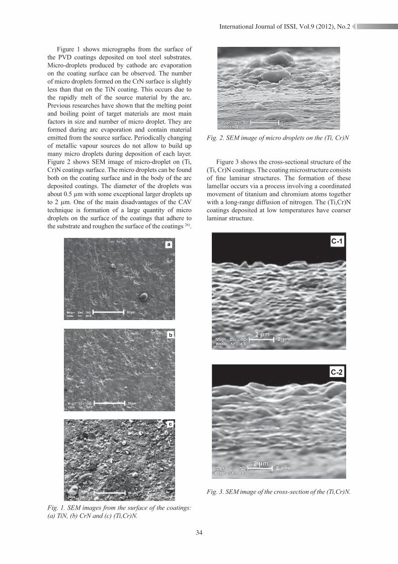
Figure 1 shows micrographs from the surface of the PVD coatings deposited on tool steel substrates. Micro-droplets produced by cathode arc evaporation on the coating surface can be observed. The number of micro droplets formed on the CrN surface is slightly less than that on the TiN coating. This occurs due to the rapidly melt of the source material by the arc. Previous researches have shown that the melting point and boiling point of target materials are most main factors in size and number of micro droplet. They are formed during arc evaporation and contain material emitted from the source surface. Periodically changing of metallic vapour sources do not allow to build up many micro droplets during deposition of each layer. Figure 2 shows SEM image of micro-droplet on (Ti, Cr)N coatings surface. The micro droplets can be found both on the coating surface and in the body of the arc deposited coatings. The diameter of the droplets was about 0.5 µm with some exceptional larger droplets up to 2 µm. One of the main disadvantages of the CAV technique is formation of a large quantity of micro droplets on the surface of the coatings that adhere to the substrate and roughen the surface of the coatings 26).
Fig. 1. SEM images from the surface of the coatings: (a) TiN, (b) CrN and (c) (Ti,Cr)N.
Fig. 2. SEM image of micro droplets on the (Ti, Cr)N
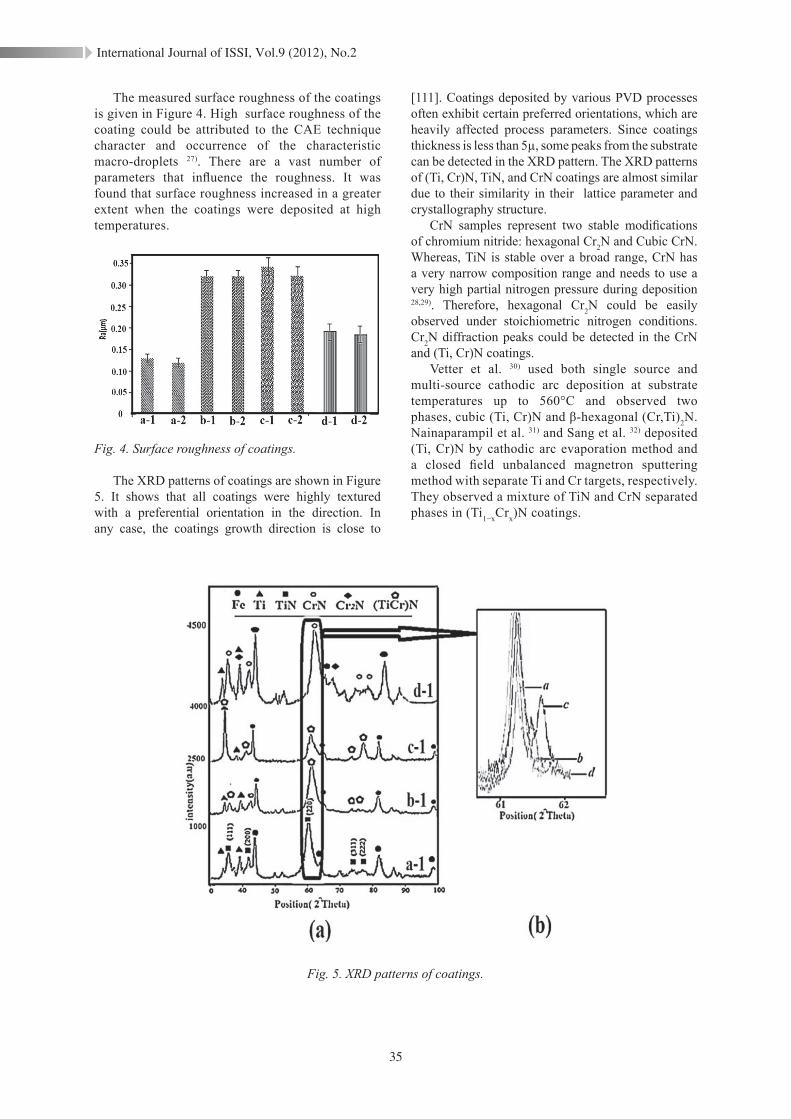
Figure 3 shows the cross-sectional structure of the (Ti, Cr)N coatings. The coating microstructure consists of fine laminar structures. The formation of these lamellar occurs via a process involving a coordinated movement of titanium and chromium atoms together with a long-range diffusion of nitrogen. The (Ti,Cr)N coatings deposited at low temperatures have coarser laminar structure.
Fig. 3. SEM image of the cross-section of the (Ti,Cr)N.
International Journal of ISSI, Vol.9 (2012), No.2
35
The measured surface roughness of the coatings is given in Figure 4. High surface roughness of the coating could be attributed to the CAE technique character and occurrence of the characteristic macro-droplets 27). There are a vast number of parameters that influence the roughness. It was found that surface roughness increased in a greater extent when the coatings were deposited at high temperatures.
Fig. 4. Surface roughness of coatings.
The XRD patterns of coatings are shown in Figure 5. It shows that all coatings were highly textured with a preferential orientation in the direction. In any case, the coatings growth direction is close to
[111]. Coatings deposited by various PVD processes often exhibit certain preferred orientations, which are heavily affected process parameters. Since coatings thickness is less than 5µ, some peaks from the substrate can be detected in the XRD pattern. The XRD patterns of (Ti, Cr)N, TiN, and CrN coatings are almost similar due to their similarity in their lattice parameter and crystallography structure.
CrN samples represent two stable modifications of chromium nitride: hexagonal Cr2N and Cubic CrN. Whereas, TiN is stable over a broad range, CrN has a very narrow composition range and needs to use a very high partial nitrogen pressure during deposition 28,29). Therefore, hexagonal Cr2N could be easily observed under stoichiometric nitrogen conditions. Cr2N diffraction peaks could be detected in the CrN and (Ti, Cr)N coatings.
Vetter et al. 30) used both single source and multi-source cathodic arc deposition at substrate temperatures up to 560°C and observed two phases, cubic (Ti, Cr)N and β-hexagonal (Cr,Ti)2N. Nainaparampil et al. 31) and Sang et al. 32) deposited (Ti, Cr)N by cathodic arc evaporation method and a closed field unbalanced magnetron sputtering method with separate Ti and Cr targets, respectively. They observed a mixture of TiN and CrN separated phases in (Ti1−xCrx)N coatings.
Fig. 5. XRD patterns of coatings.
International Journal of ISSI, Vol.9 (2012), No.2
36
Fig. 6. Diffraction angle, lattice parameter and Residual stress for coatings.
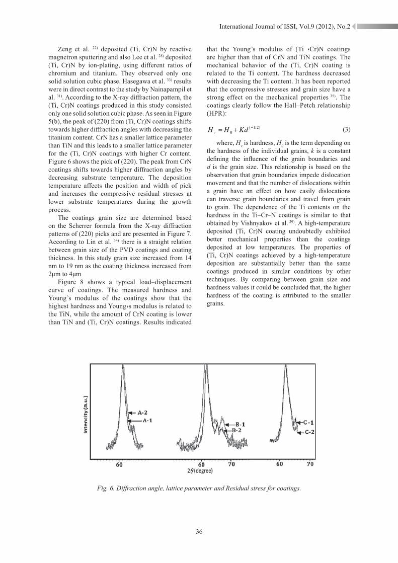
Zeng et al. 22) deposited (Ti, Cr)N by reactive magnetron sputtering and also Lee et al. 28) deposited (Ti, Cr)N by ion-plating, using different ratios of chromium and titanium. They observed only one solid solution cubic phase. Hasegawa et al. 33) results were in direct contrast to the study by Nainapampil et al. 31). According to the X-ray diffraction pattern, the (Ti, Cr)N coatings produced in this study consisted only one solid solution cubic phase. As seen in Figure 5(b), the peak of (220) from (Ti, Cr)N coatings shifts towards higher diffraction angles with decreasing the titanium content. CrN has a smaller lattice parameter than TiN and this leads to a smaller lattice parameter for the (Ti, Cr)N coatings with higher Cr content. Figure 6 shows the pick of (220). The peak from CrN coatings shifts towards higher diffraction angles by decreasing substrate temperature. The deposition temperature affects the position and width of pick and increases the compressive residual stresses at lower substrate temperatures during the growth process.
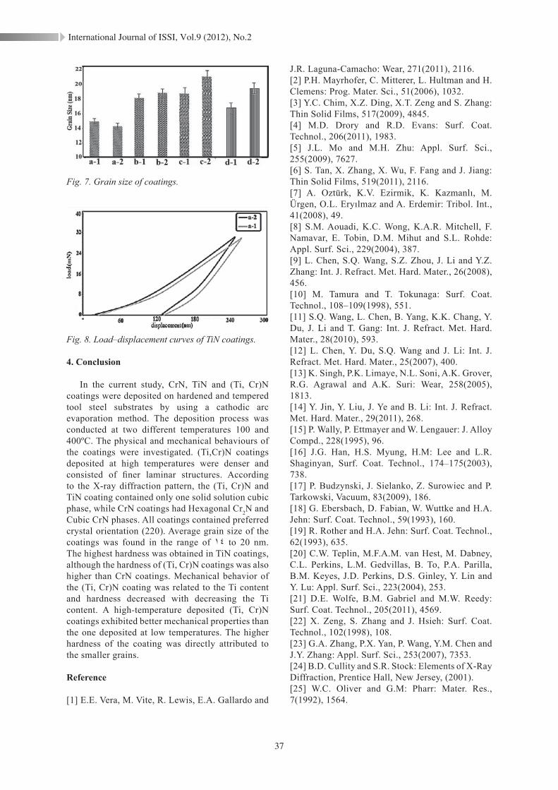
The coatings grain size are determined based on the Scherrer formula from the X-ray diffraction patterns of (220) picks and are presented in Figure 7. According to Lin et al. 34) there is a straight relation between grain size of the PVD coatings and coating thickness. In this study grain size increased from 14 nm to 19 nm as the coating thickness increased from 2μm to 4μm
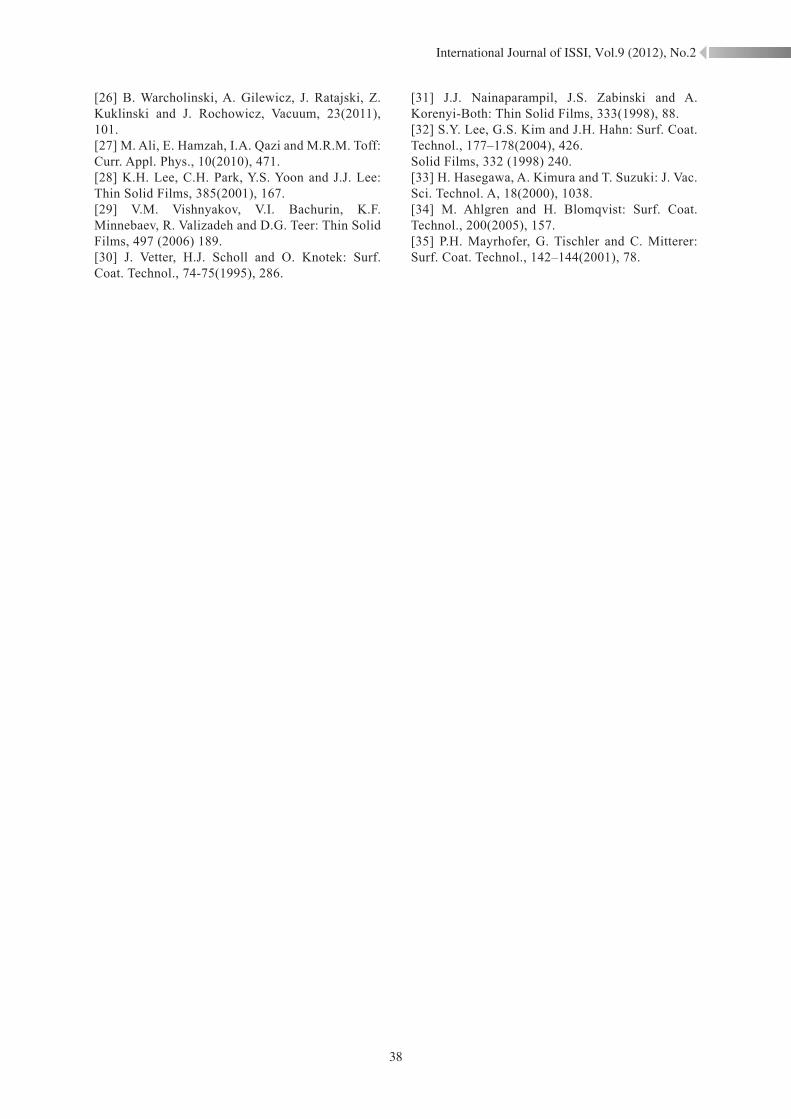
Figure 8 shows a typical load–displacement curve of coatings. The measured hardness and Young’s modulus of the coatings show that the highest hardness and Young›s modulus is related to the TiN, while the amount of CrN coating is lower than TiN and (Ti, Cr)N coatings. Results indicated
that the Young’s modulus of (Ti ،Cr)N coatings are higher than that of CrN and TiN coatings. The mechanical behavior of the (Ti, Cr)N coating is related to the Ti content. The hardness decreased with decreasing the Ti content. It has been reported that the compressive stresses and grain size have a strong effect on the mechanical properties 35). The coatings clearly follow the Hall–Petch relationship (HPR):
( 1/2)0vH H Kd −= + (3)
where, Hv is hardness, H0 is the term depending on the hardness of the individual grains, k is a constant defining the influence of the grain boundaries and d is the grain size. This relationship is based on the observation that grain boundaries impede dislocation movement and that the number of dislocations within a grain have an effect on how easily dislocations can traverse grain boundaries and travel from grain to grain. The dependence of the Ti contents on the hardness in the Ti–Cr–N coatings is similar to that obtained by Vishnyakov et al. 29). A high-temperature deposited (Ti, Cr)N coating undoubtedly exhibited better mechanical properties than the coatings deposited at low temperatures. The properties of (Ti, Cr)N coatings achieved by a high-temperature deposition are substantially better than the same coatings produced in similar conditions by other techniques. By comparing between grain size and hardness values it could be concluded that, the higher hardness of the coating is attributed to the smaller grains.
International Journal of ISSI, Vol.9 (2012), No.2
37
Fig. 7. Grain size of coatings.
Fig. 8. Load–displacement curves of TiN coatings.
4. Conclusion
In the current study, CrN, TiN and (Ti, Cr)N coatings were deposited on hardened and tempered tool steel substrates by using a cathodic arc evaporation method. The deposition process was conducted at two different temperatures 100 and 400ºC. The physical and mechanical behaviours of the coatings were investigated. (Ti,Cr)N coatings deposited at high temperatures were denser and consisted of finer laminar structures. According to the X-ray diffraction pattern, the (Ti, Cr)N and TiN coating contained only one solid solution cubic phase, while CrN coatings had Hexagonal Cr2N and Cubic CrN phases. All coatings contained preferred crystal orientation (220). Average grain size of the coatings was found in the range of 14 to 20 nm. The highest hardness was obtained in TiN coatings, although the hardness of (Ti, Cr)N coatings was also higher than CrN coatings. Mechanical behavior of the (Ti, Cr)N coating was related to the Ti content and hardness decreased with decreasing the Ti content. A high-temperature deposited (Ti, Cr)N coatings exhibited better mechanical properties than the one deposited at low temperatures. The higher hardness of the coating was directly attributed to the smaller grains.
Reference
[1] E.E. Vera, M. Vite, R. Lewis, E.A. Gallardo and
J.R. Laguna-Camacho: Wear, 271(2011), 2116.[2] P.H. Mayrhofer, C. Mitterer, L. Hultman and H. Clemens: Prog. Mater. Sci., 51(2006), 1032.[3] Y.C. Chim, X.Z. Ding, X.T. Zeng and S. Zhang: Thin Solid Films, 517(2009), 4845.[4] M.D. Drory and R.D. Evans: Surf. Coat. Technol., 206(2011), 1983.[5] J.L. Mo and M.H. Zhu: Appl. Surf. Sci., 255(2009), 7627.[6] S. Tan, X. Zhang, X. Wu, F. Fang and J. Jiang: Thin Solid Films, 519(2011), 2116.[7] A. Oztürk, K.V. Ezirmik, K. Kazmanlı, M. Ürgen, O.L. Eryılmaz and A. Erdemir: Tribol. Int., 41(2008), 49.[8] S.M. Aouadi, K.C. Wong, K.A.R. Mitchell, F. Namavar, E. Tobin, D.M. Mihut and S.L. Rohde: Appl. Surf. Sci., 229(2004), 387.[9] L. Chen, S.Q. Wang, S.Z. Zhou, J. Li and Y.Z. Zhang: Int. J. Refract. Met. Hard. Mater., 26(2008), 456.[10] M. Tamura and T. Tokunaga: Surf. Coat. Technol., 108–109(1998), 551.[11] S.Q. Wang, L. Chen, B. Yang, K.K. Chang, Y. Du, J. Li and T. Gang: Int. J. Refract. Met. Hard. Mater., 28(2010), 593.[12] L. Chen, Y. Du, S.Q. Wang and J. Li: Int. J. Refract. Met. Hard. Mater., 25(2007), 400.[13] K. Singh, P.K. Limaye, N.L. Soni, A.K. Grover, R.G. Agrawal and A.K. Suri: Wear, 258(2005), 1813.[14] Y. Jin, Y. Liu, J. Ye and B. Li: Int. J. Refract. Met. Hard. Mater., 29(2011), 268.[15] P. Wally, P. Ettmayer and W. Lengauer: J. Alloy Compd., 228(1995), 96.[16] J.G. Han, H.S. Myung, H.M: Lee and L.R. Shaginyan, Surf. Coat. Technol., 174–175(2003), 738.[17] P. Budzynski, J. Sielanko, Z. Surowiec and P. Tarkowski, Vacuum, 83(2009), 186.[18] G. Ebersbach, D. Fabian, W. Wuttke and H.A. Jehn: Surf. Coat. Technol., 59(1993), 160.[19] R. Rother and H.A. Jehn: Surf. Coat. Technol., 62(1993), 635.[20] C.W. Teplin, M.F.A.M. van Hest, M. Dabney, C.L. Perkins, L.M. Gedvillas, B. To, P.A. Parilla, B.M. Keyes, J.D. Perkins, D.S. Ginley, Y. Lin and Y. Lu: Appl. Surf. Sci., 223(2004), 253.[21] D.E. Wolfe, B.M. Gabriel and M.W. Reedy: Surf. Coat. Technol., 205(2011), 4569.[22] X. Zeng, S. Zhang and J. Hsieh: Surf. Coat. Technol., 102(1998), 108.[23] G.A. Zhang, P.X. Yan, P. Wang, Y.M. Chen and J.Y. Zhang: Appl. Surf. Sci., 253(2007), 7353.[24] B.D. Cullity and S.R. Stock: Elements of X-Ray Diffraction, Prentice Hall, New Jersey, (2001).[25] W.C. Oliver and G.M: Pharr: Mater. Res., 7(1992), 1564.
International Journal of ISSI, Vol.9 (2012), No.2
38
[26] B. Warcholinski, A. Gilewicz, J. Ratajski, Z. Kuklinski and J. Rochowicz, Vacuum, 23(2011), 101.[27] M. Ali, E. Hamzah, I.A. Qazi and M.R.M. Toff: Curr. Appl. Phys., 10(2010), 471.[28] K.H. Lee, C.H. Park, Y.S. Yoon and J.J. Lee: Thin Solid Films, 385(2001), 167.[29] V.M. Vishnyakov, V.I. Bachurin, K.F. Minnebaev, R. Valizadeh and D.G. Teer: Thin Solid Films, 497 (2006) 189.[30] J. Vetter, H.J. Scholl and O. Knotek: Surf. Coat. Technol., 74-75(1995), 286.
[31] J.J. Nainaparampil, J.S. Zabinski and A. Korenyi-Both: Thin Solid Films, 333(1998), 88.[32] S.Y. Lee, G.S. Kim and J.H. Hahn: Surf. Coat. Technol., 177–178(2004), 426.Solid Films, 332 (1998) 240.[33] H. Hasegawa, A. Kimura and T. Suzuki: J. Vac. Sci. Technol. A, 18(2000), 1038.[34] M. Ahlgren and H. Blomqvist: Surf. Coat. Technol., 200(2005), 157.[35] P.H. Mayrhofer, G. Tischler and C. Mitterer: Surf. Coat. Technol., 142–144(2001), 78.